3G3AX-RBU Regenerative Braking Unit User's Manual Documents/Omron/Omron Regen Braking Unit.pdfThank...
54
Cat. No. I563-E1-02 USER’S MANUAL 3G3AX-RBU Regenerative Braking Unit
Transcript of 3G3AX-RBU Regenerative Braking Unit User's Manual Documents/Omron/Omron Regen Braking Unit.pdfThank...

Cat. No. I563-E1-02
USER’S MANUAL
3G3AX-RBURegenerative Braking Unit
Introduction
IntroductionThank you for choosing the Regenerative Braking Unit 3G3AX-RBU. This User's Manual (hereinafter called “this manual”) describes the installation/wiring of the 3G3AX-RBU model, as well as troubleshooting and inspection methods.
This manual should be delivered to the actual end user of the product.After reading this manual, keep it handy for future reference.This manual describes the specifications and functions of the product as well as the relations between them. You should assume that anything not described in this manual is not possible with the product.Intended readers
This manual is intended for:Those with knowledge of electrical systems (qualified electrical engineers or the equivalent), and also in charge of:
• Introducing the control equipment• Designing the control system• Installing and/or connecting the control equipment• Field management
1
Read and Understand This Manual
Read and Understand This ManualPlease read and understand this manual before using the product. Please consult your OMRON representative if you have any questions or comments.
Warranty and Limitations of LiabilityWARRANTY
OMRON's exclusive warranty is that the products are free from defects in materials and workmanship for a period of one year (or other period if specified) from date of sale by OMRON.
OMRON MAKES NO WARRANTY OR REPRESENTATION, EXPRESS OR IMPLIED, REGARDING NON-INFRINGEMENT, MERCHANTABILITY, OR FITNESS FOR PARTICULAR PURPOSE OF THE PRODUCTS. ANY BUYER OR USER ACKNOWLEDGES THAT THE BUYER OR USER ALONE HASDETERMINED THAT THE PRODUCTS WILL SUITABLY MEET THE REQUIREMENTS OF THEIRINTENDED USE. OMRON DISCLAIMS ALL OTHER WARRANTIES, EXPRESS OR IMPLIED.
LIMITATIONS OF LIABILITYOMRON SHALL NOT BE RESPONSIBLE FOR SPECIAL, INDIRECT, OR CONSEQUENTIAL DAMAGES, LOSS OF PROFITS OR COMMERCIAL LOSS IN ANY WAY CONNECTED WITH THE PRODUCTS, WHETHER SUCH CLAIM IS BASED ON CONTRACT, WARRANTY, NEGLIGENCE, OR STRICT LIABILITY.
In no event shall the responsibility of OMRON for any act exceed the individual price of the product on which liability is asserted.
IN NO EVENT SHALL OMRON BE RESPONSIBLE FOR WARRANTY, REPAIR, OR OTHER CLAIMSREGARDING THE PRODUCTS UNLESS OMRON'S ANALYSIS CONFIRMS THAT THE PRODUCTSWERE PROPERLY HANDLED, STORED, INSTALLED, AND MAINTAINED AND NOT SUBJECT TOCONTAMINATION, ABUSE, MISUSE, OR INAPPROPRIATE MODIFICATION OR REPAIR.
2
Read and Understand This Manual
Application ConsiderationsSUITABILITY FOR USE
OMRON shall not be responsible for conformity with any standards, codes, or regulations that apply tothe combination of products in the customer's application or use of the products.
At the customer's request, OMRON will provide applicable third party certification documents identifyingratings and limitations of use that apply to the products. This information by itself is not sufficient for acomplete determination of the suitability of the products in combination with the end product, machine,system, or other application or use.
The following are some examples of applications for which particular attention must be given. This is notintended to be an exhaustive list of all possible uses of the products, nor is it intended to imply that theuses listed may be suitable for the products:
• Outdoor use, uses involving potential chemical contamination or electrical interference, or conditionsor uses not described in this manual.
• Nuclear energy control systems, combustion systems, railroad systems, aviation systems, medicalequipment, amusement machines, vehicles, safety equipment, and installations subject to separateindustry or government regulations.
• Systems, machines, and equipment that could present a risk to life or property.
Please know and observe all prohibitions of use applicable to the products.
NEVER USE THE PRODUCTS FOR AN APPLICATION INVOLVING SERIOUS RISK TO LIFE ORPROPERTY WITHOUT ENSURING THAT THE SYSTEM AS A WHOLE HAS BEEN DESIGNED TOADDRESS THE RISKS, AND THAT THE OMRON PRODUCTS ARE PROPERLY RATED ANDINSTALLED FOR THE INTENDED USE WITHIN THE OVERALL EQUIPMENT OR SYSTEM.
PROGRAMMABLE PRODUCTSOMRON shall not be responsible for the user's programming of a programmable product, or anyconsequence thereof.
3
Read and Understand This Manual
DisclaimersCHANGE IN SPECIFICATIONS
Product specifications and accessories may be changed at any time based on improvements and otherreasons.
It is our practice to change model numbers when published ratings or features are changed, or whensignificant construction changes are made. However, some specifications of the products may bechanged without any notice. When in doubt, special model numbers may be assigned to fix or establishkey specifications for your application on your request. Please consult with your OMRON representativeat any time to confirm actual specifications of purchased products.
DIMENSIONS AND WEIGHTSDimensions and weights are nominal and are not to be used for manufacturing purposes, even whentolerances are shown.
PERFORMANCE DATAPerformance data given in this manual is provided as a guide for the user in determining suitability anddoes not constitute a warranty. It may represent the result of OMRON's test conditions, and the usersmust correlate it to actual application requirements. Actual performance is subject to the OMRONWarranty and Limitations of Liability.
ERRORS AND OMISSIONSThe information in this manual has been carefully checked and is believed to be accurate; however, noresponsibility is assumed for clerical, typographical, or proofreading errors, or omissions.
4
Safety Precautions
Safety Precautions
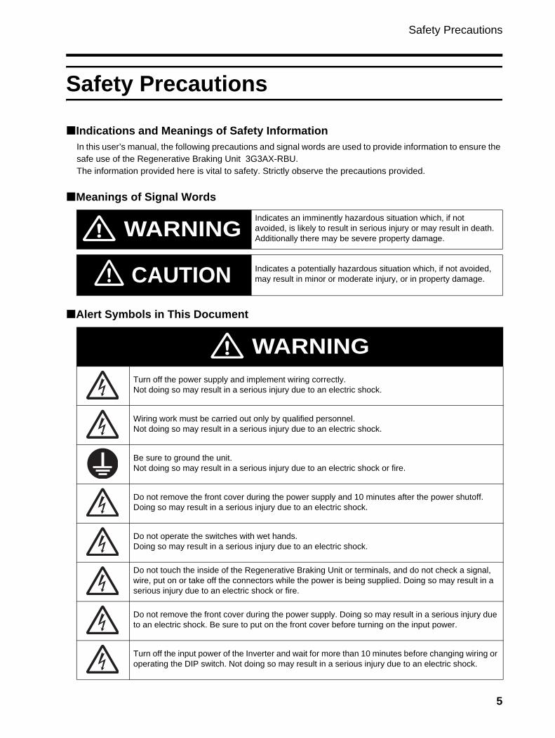
Indications and Meanings of Safety InformationIn this user’s manual, the following precautions and signal words are used to provide information to ensure the safe use of the Regenerative Braking Unit 3G3AX-RBU.The information provided here is vital to safety. Strictly observe the precautions provided.
Meanings of Signal Words
Alert Symbols in This Document
Indicates an imminently hazardous situation which, if not avoided, is likely to result in serious injury or may result in death. Additionally there may be severe property damage.
Indicates a potentially hazardous situation which, if not avoided, may result in minor or moderate injury, or in property damage.
WARNING
CAUTION
Turn off the power supply and implement wiring correctly.Not doing so may result in a serious injury due to an electric shock.
Wiring work must be carried out only by qualified personnel.Not doing so may result in a serious injury due to an electric shock.
Be sure to ground the unit.Not doing so may result in a serious injury due to an electric shock or fire.
Do not remove the front cover during the power supply and 10 minutes after the power shutoff. Doing so may result in a serious injury due to an electric shock.
Do not operate the switches with wet hands. Doing so may result in a serious injury due to an electric shock.
Do not touch the inside of the Regenerative Braking Unit or terminals, and do not check a signal, wire, put on or take off the connectors while the power is being supplied. Doing so may result in a serious injury due to an electric shock or fire.
Do not remove the front cover during the power supply. Doing so may result in a serious injury due to an electric shock. Be sure to put on the front cover before turning on the input power.
Turn off the input power of the Inverter and wait for more than 10 minutes before changing wiring or operating the DIP switch. Not doing so may result in a serious injury due to an electric shock.
WARNING
5
Safety Precautions
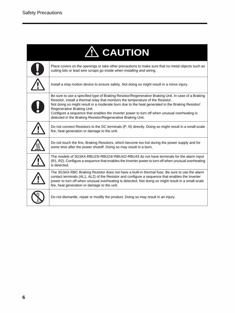
Place covers on the openings or take other precautions to make sure that no metal objects such as cutting bits or lead wire scraps go inside when installing and wiring.
Install a stop motion device to ensure safety. Not doing so might result in a minor injury.
Be sure to use a specified type of Braking Resistor/Regenerative Braking Unit. In case of a Braking Resistor, install a thermal relay that monitors the temperature of the Resistor.Not doing so might result in a moderate burn due to the heat generated in the Braking Resistor/Regenerative Braking Unit.Configure a sequence that enables the Inverter power to turn off when unusual overheating is detected in the Braking Resistor/Regenerative Braking Unit.
Do not connect Resistors to the DC terminals (P, N) directly. Doing so might result in a small-scale fire, heat generation or damage to the unit.
Do not touch the fins, Braking Resistors, which become too hot during the power supply and for some time after the power shutoff. Doing so may result in a burn.
The models of 3G3AX-RBU23/-RBU24/-RBU42/-RBU43 do not have terminals for the alarm input (R1, R2). Configure a sequence that enables the Inverter power to turn off when unusual overheating is detected.
The 3G3AX-RBC Braking Resistor does not have a built-in thermal fuse. Be sure to use the alarm contact terminals (AL1, AL2) of the Resistor and configure a sequence that enables the Inverter power to turn off when unusual overheating is detected. Not doing so might result in a small-scale fire, heat generation or damage to the unit.
Do not dismantle, repair or modify the product. Doing so may result in an injury.
CAUTION
6

Safety Precautions
Installation and Wiring
Turn off the power supply and implement wiring correctly.Not doing so may result in a serious injury due to an electric shock.
Wiring work must be carried out only by qualified personnel.Not doing so may result in a serious injury due to an electric shock.
Be sure to ground the unit.Not doing so may result in a serious injury due to an electric shock or fire.
Place covers on the openings or take other precautions to make sure that no metal objects such as cutting bits or lead wire scraps go inside when installing and wiring.
Install a stop motion device to ensure safety. Not doing so might result in a minor injury.
Be sure to use a specified type of Braking Resistor/Regenerative Braking Unit. In case of a Braking Resistor, install a thermal relay that monitors the temperature of the Resistor.Not doing so might result in a moderate burn due to the heat generated in the Braking Resistor/Regenerative Braking Unit.Configure a sequence that enables the Inverter power to turn off when unusual overheating is detected in the Braking Resistor/Regenerative Braking Unit.
Do not connect Resistors to the DC terminals (P, N) directly. Doing so might result in a small-scale fire, heat generation or damage to the unit.
WARNING
CAUTION
7
Safety Precautions
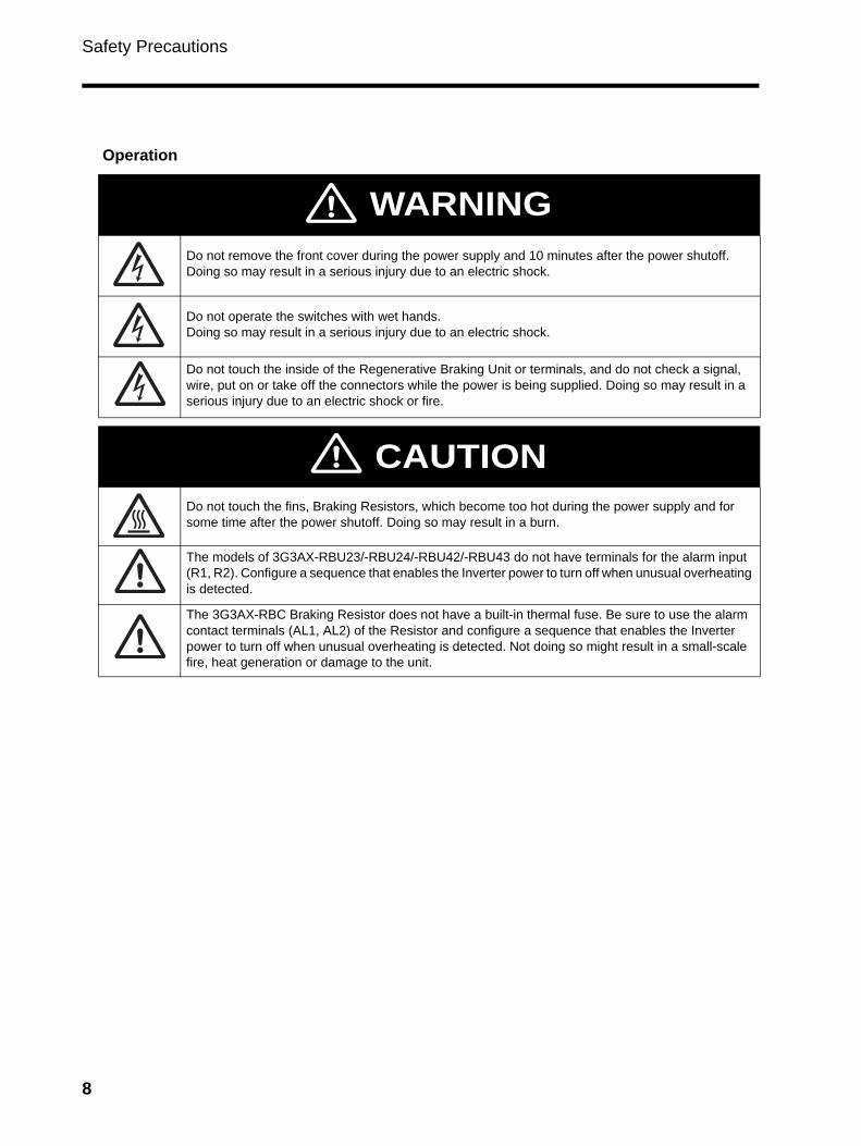
Operation
Do not remove the front cover during the power supply and 10 minutes after the power shutoff.Doing so may result in a serious injury due to an electric shock.
Do not operate the switches with wet hands. Doing so may result in a serious injury due to an electric shock.
Do not touch the inside of the Regenerative Braking Unit or terminals, and do not check a signal, wire, put on or take off the connectors while the power is being supplied. Doing so may result in a serious injury due to an electric shock or fire.
Do not touch the fins, Braking Resistors, which become too hot during the power supply and for some time after the power shutoff. Doing so may result in a burn.
The models of 3G3AX-RBU23/-RBU24/-RBU42/-RBU43 do not have terminals for the alarm input (R1, R2). Configure a sequence that enables the Inverter power to turn off when unusual overheating is detected.
The 3G3AX-RBC Braking Resistor does not have a built-in thermal fuse. Be sure to use the alarm contact terminals (AL1, AL2) of the Resistor and configure a sequence that enables the Inverter power to turn off when unusual overheating is detected. Not doing so might result in a small-scale fire, heat generation or damage to the unit.
WARNING
CAUTION
8
Safety Precautions
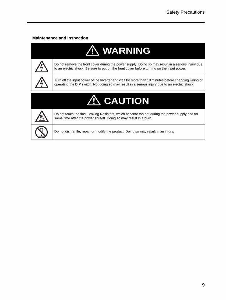
Maintenance and Inspection
Do not remove the front cover during the power supply. Doing so may result in a serious injury due to an electric shock. Be sure to put on the front cover before turning on the input power.
Turn off the input power of the Inverter and wait for more than 10 minutes before changing wiring or operating the DIP switch. Not doing so may result in a serious injury due to an electric shock.
Do not touch the fins, Braking Resistors, which become too hot during the power supply and for some time after the power shutoff. Doing so may result in a burn.
Do not dismantle, repair or modify the product. Doing so may result in an injury.
WARNING
CAUTION
9
Precautions for Safe Use
Precautions for Safe Use
Installation and StorageDo not store or use the product in the following places.
• Locations subject to direct sunlight.• Locations subject to ambient temperature exceeding the specifications.• Locations subject to relative humidity exceeding the specifications.• Locations subject to condensation due to severe temperature fluctuations.• Locations subject to corrosive or flammable gases.• Locations subject to exposure to combustibles.• Locations subject to dust (especially iron dust) or salt.• Locations subject to exposure to water, oil, or chemicals.• Locations subject to shock or vibration.
Transportation, Installation, and WiringObserve the following instructions during transportation, installation, and wiring.
• Do not drop or apply a strong impact on the product. Doing so may result in damaged parts or malfunction.
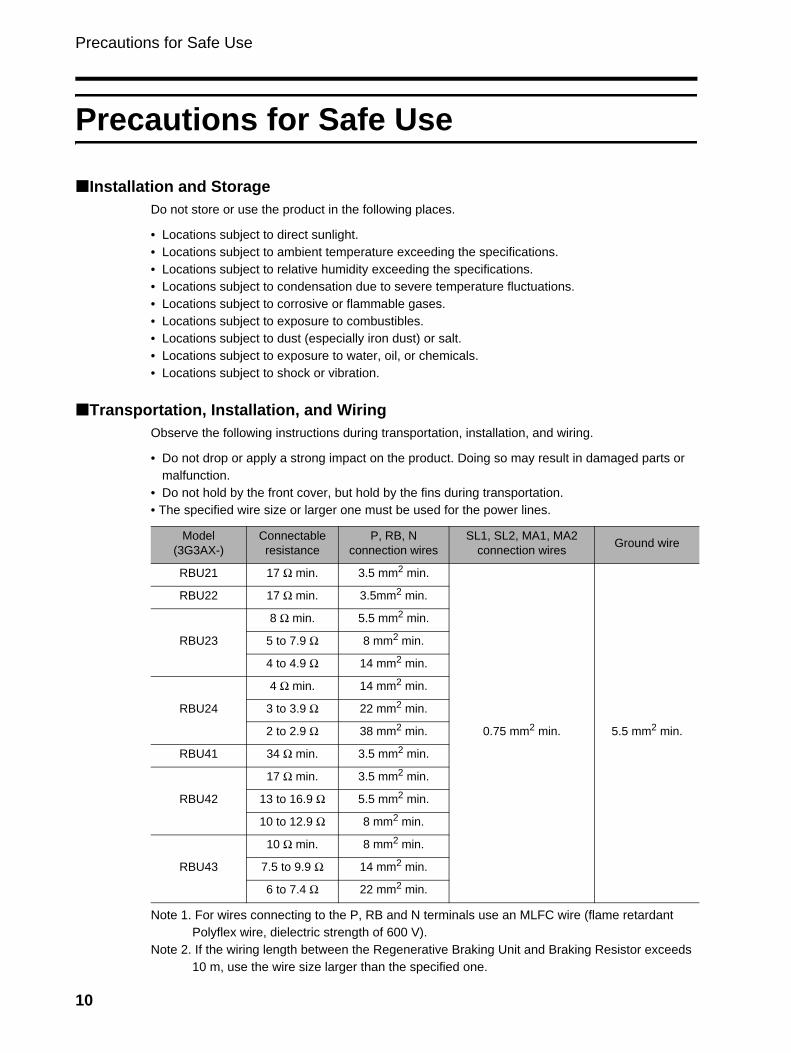
• Do not hold by the front cover, but hold by the fins during transportation.• The specified wire size or larger one must be used for the power lines.
Note 1. For wires connecting to the P, RB and N terminals use an MLFC wire (flame retardant Polyflex wire, dielectric strength of 600 V).
Note 2. If the wiring length between the Regenerative Braking Unit and Braking Resistor exceeds 10 m, use the wire size larger than the specified one.
Model(3G3AX-)
Connectable resistance
P, RB, Nconnection wires
SL1, SL2, MA1, MA2connection wires Ground wire
RBU21 17 Ω min. 3.5 mm2 min.
0.75 mm2 min. 5.5 mm2 min.
RBU22 17 Ω min. 3.5mm2 min.
RBU23
8 Ω min. 5.5 mm2 min.
5 to 7.9 Ω 8 mm2 min.
4 to 4.9 Ω 14 mm2 min.
RBU24
4 Ω min. 14 mm2 min.
3 to 3.9 Ω 22 mm2 min.
2 to 2.9 Ω 38 mm2 min.
RBU41 34 Ω min. 3.5 mm2 min.
RBU42
17 Ω min. 3.5 mm2 min.
13 to 16.9 Ω 5.5 mm2 min.
10 to 12.9 Ω 8 mm2 min.
RBU43
10 Ω min. 8 mm2 min.
7.5 to 9.9 Ω 14 mm2 min.
6 to 7.4 Ω 22 mm2 min.
10

Precautions for Safe Use
A wire of more than 10 m to 25 m : One rank higher wire sizeA wire of more than 25 m to 50 m : Two ranks higher wire size
For the 3G3AX-RBU42 model, keep the wiring length between the Regenerative Braking Unit and Braking Resistor within 5 m.
Maintenance and InspectionBe sure to confirm safety before conducting maintenance, inspection or parts replacement.
11
Precautions for Correct Use
Precautions for Correct Use
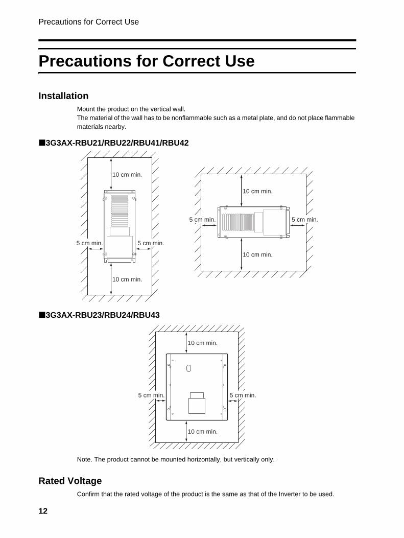
InstallationMount the product on the vertical wall.The material of the wall has to be nonflammable such as a metal plate, and do not place flammable materials nearby.
3G3AX-RBU21/RBU22/RBU41/RBU42
3G3AX-RBU23/RBU24/RBU43
Note. The product cannot be mounted horizontally, but vertically only.
Rated VoltageConfirm that the rated voltage of the product is the same as that of the Inverter to be used.
10 cm min.
10 cm min.
5 cm min.5 cm min.
10 cm min.
10 cm min.
5 cm min.5 cm min.
10 cm min.
10 cm min.
5 cm min.5 cm min.
12
Precautions for Correct Use
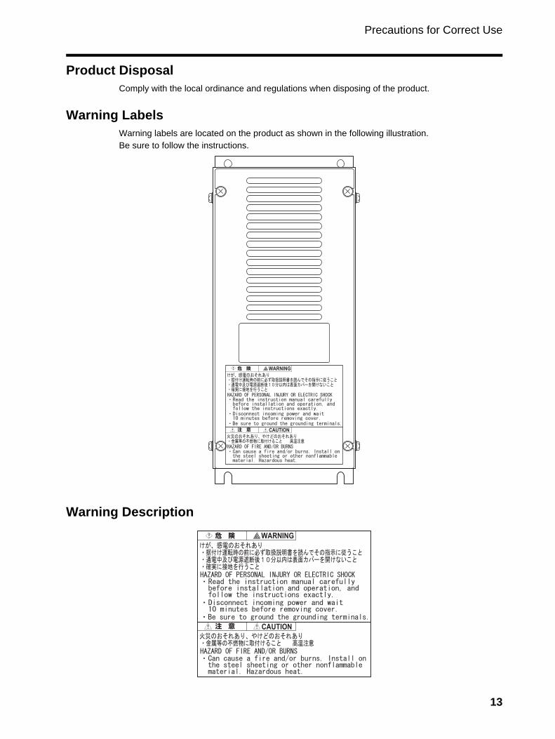
Product DisposalComply with the local ordinance and regulations when disposing of the product.
Warning LabelsWarning labels are located on the product as shown in the following illustration.Be sure to follow the instructions.
Warning Description
13
Checking Before Unpacking
Checking Before Unpacking
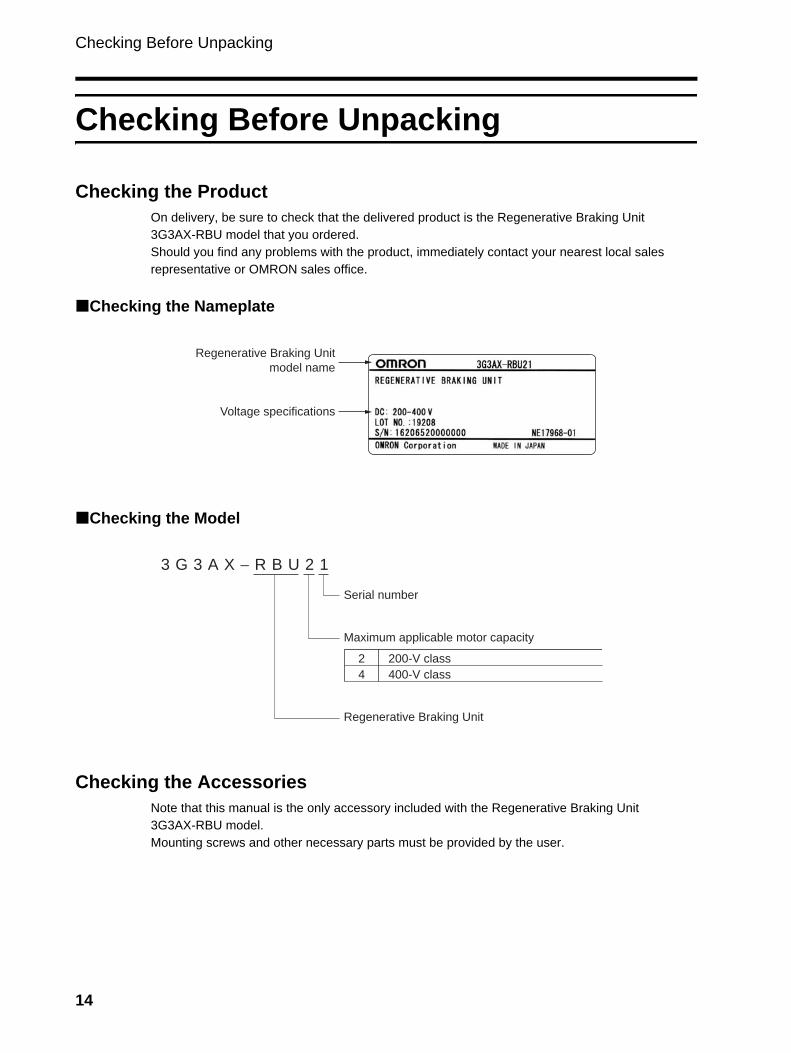
Checking the ProductOn delivery, be sure to check that the delivered product is the Regenerative Braking Unit 3G3AX-RBU model that you ordered.Should you find any problems with the product, immediately contact your nearest local sales representative or OMRON sales office.
Checking the Nameplate
Checking the Model
Checking the AccessoriesNote that this manual is the only accessory included with the Regenerative Braking Unit 3G3AX-RBU model.Mounting screws and other necessary parts must be provided by the user.
Regenerative Braking Unitmodel name
Voltage specifications
3 G 3 A X − R B U 2 1
Maximum applicable motor capacity
2
4
200-V class
400-V class
Regenerative Braking Unit
Serial number
14
Revision History
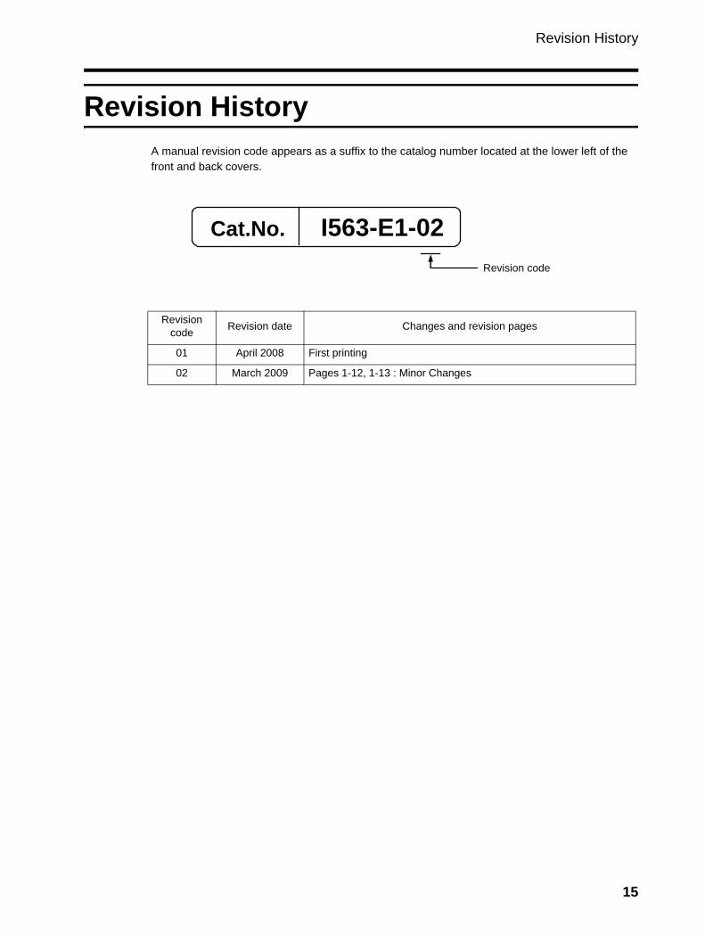
Revision HistoryA manual revision code appears as a suffix to the catalog number located at the lower left of the front and back covers.
Cat.No. I563-E1-02
Revision code
Revision code Revision date Changes and revision pages
01 April 2008 First printing
02 March 2009 Pages 1-12, 1-13 : Minor Changes
15
About This Manual
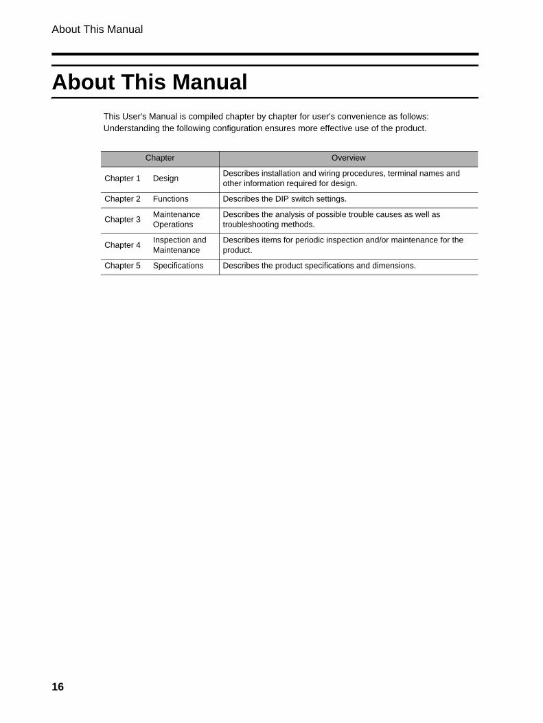
About This ManualThis User's Manual is compiled chapter by chapter for user's convenience as follows:Understanding the following configuration ensures more effective use of the product.
Chapter Overview
Chapter 1 Design Describes installation and wiring procedures, terminal names and other information required for design.
Chapter 2 Functions Describes the DIP switch settings.
Chapter 3 Maintenance Operations
Describes the analysis of possible trouble causes as well as troubleshooting methods.
Chapter 4 Inspection and Maintenance
Describes items for periodic inspection and/or maintenance for the product.
Chapter 5 Specifications Describes the product specifications and dimensions.
16
Contents
Introduction..............................................................................................1Read and Understand This Manual.........................................................2Safety Precautions ..................................................................................5Precautions for Safe Use.........................................................................10Precautions for Correct Use ....................................................................12Checking Before Unpacking ....................................................................14Revision History.......................................................................................15About This Manual...................................................................................16Chapter 1 Design1-1 Wiring.......................................................................................................1-11-2 Terminals .................................................................................................1-31-3 Removing the Built-in Resistor ................................................................1-61-4 Connection...............................................................................................1-7
Chapter 2 Functions2-1 DIP Switch Setting ...................................................................................2-1
Chapter 3 Maintenance Operations3-1 Precautions before Operation..................................................................3-13-2 When the Alarm Contact is Activated ......................................................3-23-3 When an Inverter Overvoltage Trip Occurs .............................................3-3
Chapter 4 Inspection and Maintenance4-1 Inspection and Maintenance....................................................................4-14-2 Daily Inspection and Periodic Inspection .................................................4-24-3 Megger Test.............................................................................................4-44-4 Checking the Main Element.....................................................................4-54-5 Capacitor Life Curve ................................................................................4-6
Chapter 5 Specifications5-1 Standard Specification List ......................................................................5-15-2 Dimensional Drawing...............................................................................5-5
17
Chapter 1Design
1-1 Wiring ................................................................ 1-11-2 Terminals .......................................................... 1-31-3 Removing the Built-in Resistor....................... 1-61-4 Connection ....................................................... 1-7
1-1 Wiring
1
Des
ign
1Design
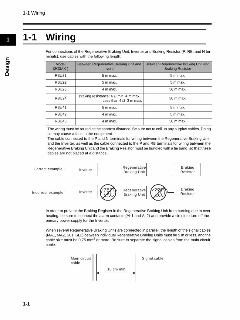
1-1 WiringFor connections of the Regenerative Braking Unit, Inverter and Braking Resistor (P, RB, and N ter-minals), use cables with the following length:
The wiring must be routed at the shortest distance. Be sure not to coil up any surplus cables. Doing so may cause a fault in the equipment.The cable connected to the P and N terminals for wiring between the Regenerative Braking Unit and the Inverter, as well as the cable connected to the P and RB terminals for wiring between the Regenerative Braking Unit and the Braking Resistor must be bundled with a tie band, so that these cables are not placed at a distance.
In order to prevent the Braking Register in the Regenerative Braking Unit from burning due to over-heating, be sure to connect the alarm contacts (AL1 and AL2) and provide a circuit to turn off the primary power supply for the Inverter.
When several Regenerative Braking Units are connected in parallel, the length of the signal cables (MA1, MA2, SL1, SL2) between individual Regenerative Braking Units must be 5 m or less, and the cable size must be 0.75 mm2 or more. Be sure to separate the signal cables from the main circuit cable.
Model(3G3AX-)
Between Regenerative Braking Unit and Inverter
Between Regenerative Braking Unit and Braking Resistor
RBU21 5 m max. 5 m max.
RBU22 5 m max. 5 m max.
RBU23 4 m max. 50 m max.
RBU24 Braking resistance: 4 Ω min. 4 m max.Less than 4 Ω 3 m max. 50 m max.
RBU41 5 m max. 5 m max.
RBU42 4 m max. 5 m max.
RBU43 4 m max. 50 m max.
Correct example :
Incorrect example :
InverterBraking
Resistor
Regenerative
Braking Unit
InverterRegenerative
Braking Unit
Braking
Resistor
Main circuit
cable
Signal cable
10 cm min.
1-1
1-1 Wiring
1
Design
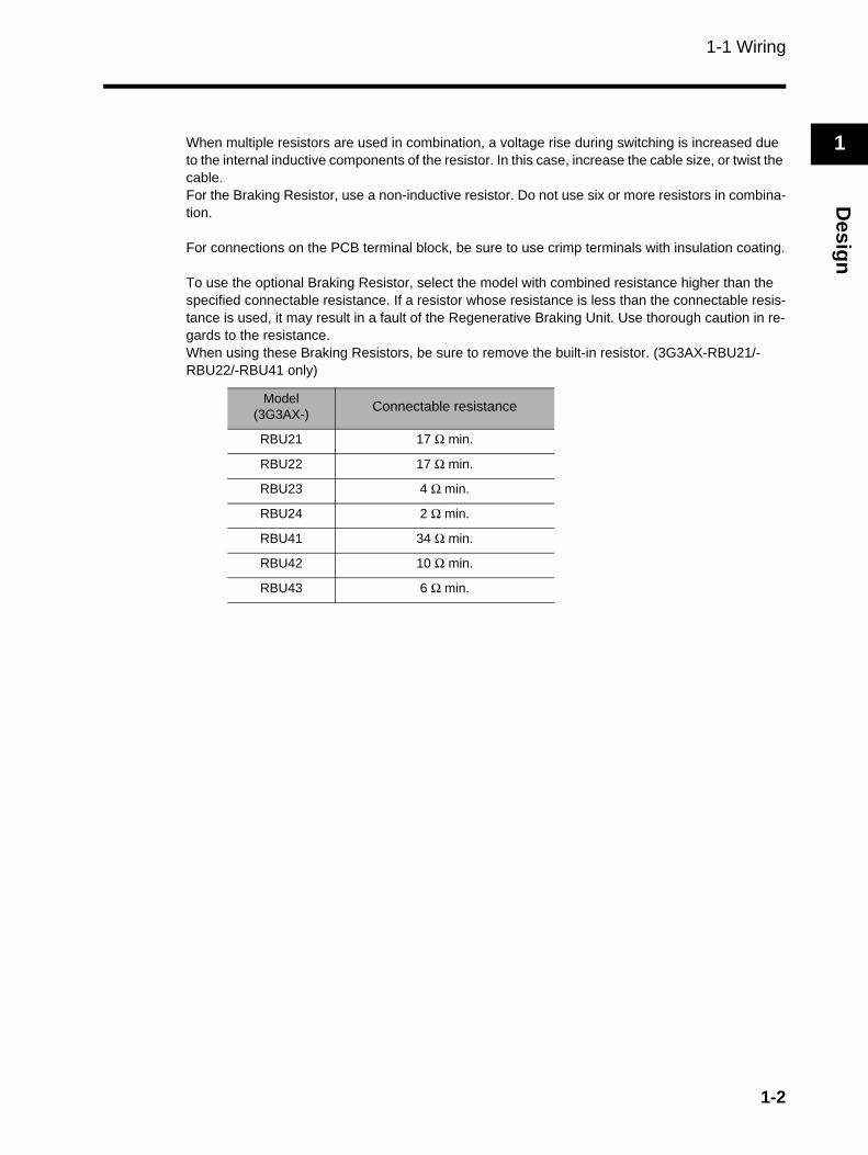
When multiple resistors are used in combination, a voltage rise during switching is increased due to the internal inductive components of the resistor. In this case, increase the cable size, or twist the cable.For the Braking Resistor, use a non-inductive resistor. Do not use six or more resistors in combina-tion.
For connections on the PCB terminal block, be sure to use crimp terminals with insulation coating.
To use the optional Braking Resistor, select the model with combined resistance higher than the specified connectable resistance. If a resistor whose resistance is less than the connectable resis-tance is used, it may result in a fault of the Regenerative Braking Unit. Use thorough caution in re-gards to the resistance.When using these Braking Resistors, be sure to remove the built-in resistor. (3G3AX-RBU21/-RBU22/-RBU41 only)
Model(3G3AX-) Connectable resistance
RBU21 17 Ω min.
RBU22 17 Ω min.
RBU23 4 Ω min.
RBU24 2 Ω min.
RBU41 34 Ω min.
RBU42 10 Ω min.
RBU43 6 Ω min.
1-2
1-2 Terminals
1
Des
ign
1-2 Terminals
Terminal Position and Arrangement
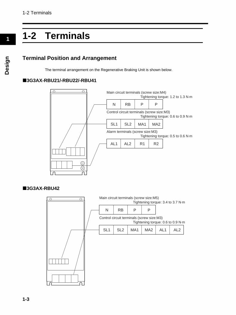
The terminal arrangement on the Regenerative Braking Unit is shown below.
3G3AX-RBU21/-RBU22/-RBU41
3G3AX-RBU42
Main circuit terminals (screw size:M4)
Tightening torque: 1.2 to 1.3 N⋅m
Alarm terminals (screw size:M3)
Tightening torque: 0.5 to 0.6 N⋅m
N RB P P
SL1 SL2 MA1 MA2
AL1 AL2 R1 R2
Control circuit terminals (screw size:M3)
Tightening torque: 0.6 to 0.9 N⋅m
Main circuit terminals (screw size:M5)
Tightening torque: 3.4 to 3.7 N⋅m
SL1 SL2 MA1
N RB P P
MA2 AL1 AL2
Control circuit terminals (screw size:M3)
Tightening torque: 0.6 to 0.9 N⋅m
1-3
1-2 Terminals
1
Design
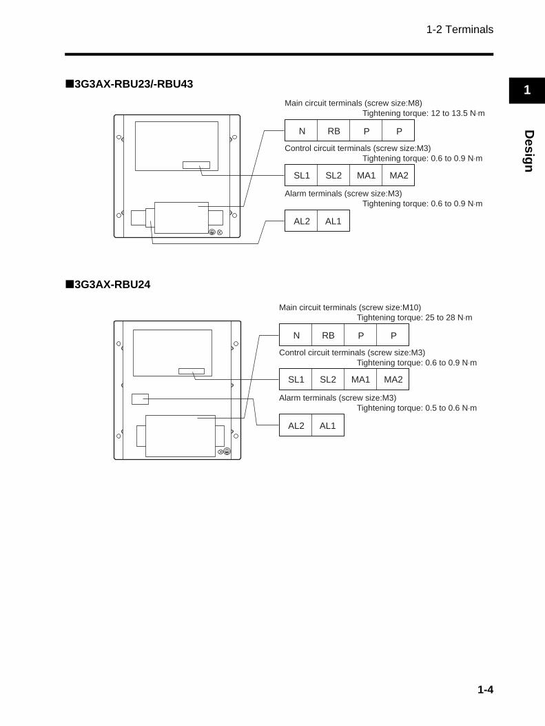
3G3AX-RBU23/-RBU43
3G3AX-RBU24
SL1 SL2 MA1 MA2
N RB P P
AL2 AL1
Main circuit terminals (screw size:M8)
Tightening torque: 12 to 13.5 N⋅m
Alarm terminals (screw size:M3)
Tightening torque: 0.6 to 0.9 N⋅m
Control circuit terminals (screw size:M3)
Tightening torque: 0.6 to 0.9 N⋅m
SL1 SL2 MA1 MA2
N RB P P
AL2 AL1
Main circuit terminals (screw size:M10)
Tightening torque: 25 to 28 N⋅m
Alarm terminals (screw size:M3)
Tightening torque: 0.5 to 0.6 N⋅m
Control circuit terminals (screw size:M3)
Tightening torque: 0.6 to 0.9 N⋅m
1-4
1-2 Terminals
1
Des
ign
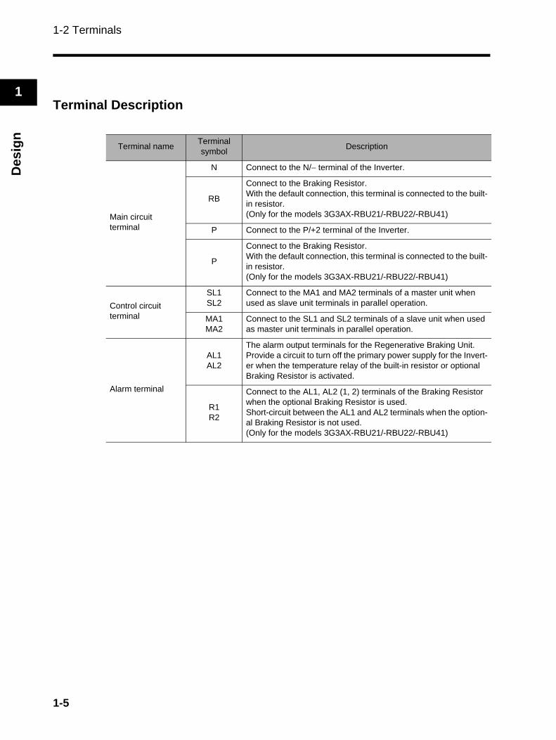
Terminal Description
Terminal name Terminal symbol Description
Main circuitterminal
N Connect to the N/− terminal of the Inverter.
RB
Connect to the Braking Resistor.With the default connection, this terminal is connected to the built-in resistor.(Only for the models 3G3AX-RBU21/-RBU22/-RBU41)
P Connect to the P/+2 terminal of the Inverter.
P
Connect to the Braking Resistor.With the default connection, this terminal is connected to the built-in resistor.(Only for the models 3G3AX-RBU21/-RBU22/-RBU41)
Control circuitterminal
SL1SL2
Connect to the MA1 and MA2 terminals of a master unit when used as slave unit terminals in parallel operation.
MA1MA2
Connect to the SL1 and SL2 terminals of a slave unit when used as master unit terminals in parallel operation.
Alarm terminal
AL1AL2
The alarm output terminals for the Regenerative Braking Unit.Provide a circuit to turn off the primary power supply for the Invert-er when the temperature relay of the built-in resistor or optional Braking Resistor is activated.
R1R2
Connect to the AL1, AL2 (1, 2) terminals of the Braking Resistor when the optional Braking Resistor is used.Short-circuit between the AL1 and AL2 terminals when the option-al Braking Resistor is not used.(Only for the models 3G3AX-RBU21/-RBU22/-RBU41)
1-5
1-3 Removing the Built-in Resistor
1
Design
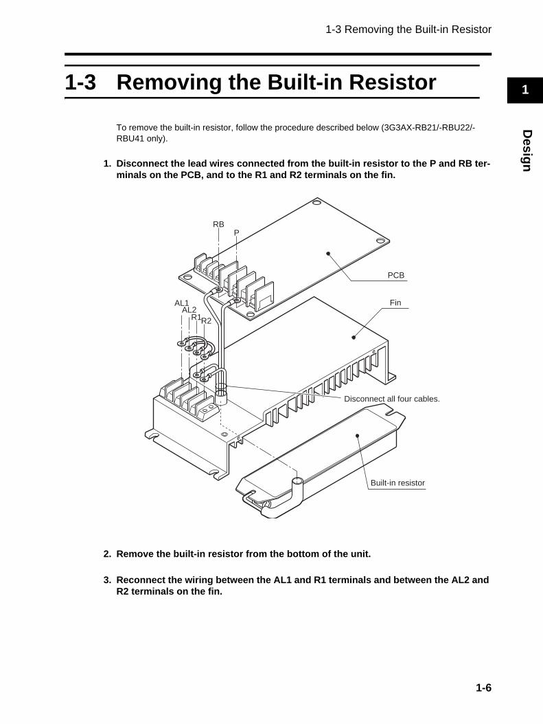
1-3 Removing the Built-in Resistor
To remove the built-in resistor, follow the procedure described below (3G3AX-RB21/-RBU22/-RBU41 only).
1. Disconnect the lead wires connected from the built-in resistor to the P and RB ter-minals on the PCB, and to the R1 and R2 terminals on the fin.
2. Remove the built-in resistor from the bottom of the unit.
3. Reconnect the wiring between the AL1 and R1 terminals and between the AL2 and R2 terminals on the fin.
PCB
Fin
Built-in resistor
Disconnect all four cables.
RBP
AL1AL2
R1R2
1-6
1-4 Connection
1
Des
ign
1-4 Connection
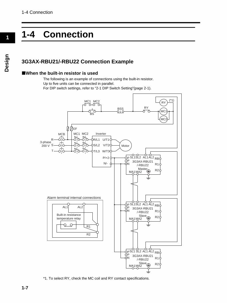
3G3AX-RBU21/-RBU22 Connection Example
When the built-in resistor is usedThe following is an example of connections using the built-in resistor.Up to five units can be connected in parallel.For DIP switch settings, refer to "2-1 DIP Switch Setting"(page 2-1).
*1. To select RY, check the MC coil and RY contact specifications.
R
S
T
Inverter
R/L1
S/L2
T/L3
MCB MC1
EF
U/T1
V/T2
W/T3
P/+2
N/-
Motor
PPN
SL1SL2 AL1AL2 RB
R1
R2MA1MA2
3G3AX-RBU21
/-RBU22
Master
PPN
SL1SL2 AL1 AL2 RB
R1
R2MA1MA2
3G3AX-RBU21
/-RBU22
Slave
PPN
SL1 SL2 AL1 AL2 RB
R1
R2MA1MA2
3G3AX-RBU21
/-RBU22
Slave
MC1
BS
BSS RY
RY
MC1
(*1)
3-phase
200 V
AL1 AL2
R1
R2
Built-in resistance
temperature relay
Alarm terminal internal connections
MC2
MC2
MC2
1-7
1-4 Connection
1
Design
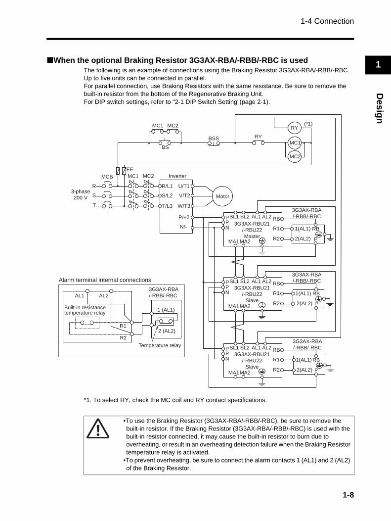
When the optional Braking Resistor 3G3AX-RBA/-RBB/-RBC is usedThe following is an example of connections using the Braking Resistor 3G3AX-RBA/-RBB/-RBC.Up to five units can be connected in parallel.For parallel connection, use Braking Resistors with the same resistance. Be sure to remove the built-in resistor from the bottom of the Regenerative Braking Unit.For DIP switch settings, refer to "2-1 DIP Switch Setting"(page 2-1).
*1. To select RY, check the MC coil and RY contact specifications.
1(AL1)
2(AL2) P
RB
1(AL1)
2(AL2) P
RB
R
S
T
MCB MC1
EF
PPN
SL1 SL2 AL1 AL2 RB
R1
R2MA1MA2
3G3AX-RBU21
/-RBU22
Master
PPN
SL1 SL2 AL1 AL2 RB
R1
R2MA1MA2
3G3AX-RBU21
/-RBU22
Slave
PPN
SL1 SL2 AL1 AL2 RB
R1
R2MA1MA2
3G3AX-RBU21
/-RBU22
Slave
BS
BSS RY
RY
MC1
(*1)
1(AL1)
2(AL2) P
RB
R/L1
S/L2
T/L3
U/T1
V/T2
W/T3
P/+2
N/-
AL1 AL2
R1
R2
Built-in resistancetemperature relay
2 (AL2)
1 (AL1)
Temperature relay
3G3AX-RBA
/-RBB/-RBC
3G3AX-RBA
/-RBB/-RBC
3G3AX-RBA
/-RBB/-RBC
3G3AX-RBA
/-RBB/-RBC
Alarm terminal internal connections
MC2
MC1 MC2
MC2
3-phase
200 V
Inverter
Motor
•To use the Braking Resistor (3G3AX-RBA/-RBB/-RBC), be sure to remove the built-in resistor. If the Braking Resistor (3G3AX-RBA/-RBB/-RBC) is used with the built-in resistor connected, it may cause the built-in resistor to burn due to overheating, or result in an overheating detection failure when the Braking Resistor temperature relay is activated.
•To prevent overheating, be sure to connect the alarm contacts 1 (AL1) and 2 (AL2) of the Braking Resistor.
1-8

1-4 Connection
1
Des
ign
3G3AX-RBU41 Connection example
When the built-in resistor is usedThe following is an example of connections using the built-in resistor.Up to five units can be connected in parallel.For DIP switch settings, refer to "2-1 DIP Switch Setting"(page 2-1).
*1. To select RY, check the MC coil and RY contact specifications.
R
S
T
MCB MC1
PPN
SL1 SL2 AL1 AL2 RB
R1
R2MA1MA2
3G3AX-RBU41
Master
PPN
SL1 SL2 AL1 AL2 RB
R1
R2MA1MA2
3G3AX-RBU41
Slave
PPN
SL1 SL2 AL1 AL2 RB
R1
R2MA1MA2
3G3AX-RBU41
Slave
BS
BSS RY
RY
MC1
(*1)
200 V 50/60 Hz
220 V 60 Hz
Operation power
supply
R/L1
S/L2
T/L3
U/T1
V/T2
W/T3
P/+2
N/-
AL1 AL2
R1
R2
Built-in resistance
temperature relay
Alarm terminal internal connections
MC2
MC1 MC2
MC2
Inverter
Motor3-phase
400 V
1-9
1-4 Connection
1
Design
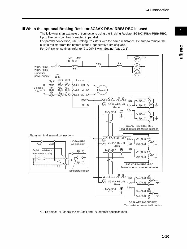
When the optional Braking Resistor 3G3AX-RBA/-RBB/-RBC is usedThe following is an example of connections using the Braking Resistor 3G3AX-RBA/-RBB/-RBC.Up to five units can be connected in parallel.For parallel connection, use Braking Resistors with the same resistance. Be sure to remove the built-in resistor from the bottom of the Regenerative Braking Unit.For DIP switch settings, refer to "2-1 DIP Switch Setting"(page 2-1).
*1. To select RY, check the MC coil and RY contact specifications.
R
S
T
MCB MC1
PPN
SL1 SL2 AL1 AL2 RB
R1
R2MA1MA2
3G3AX-RBU41
Master
PPN
SL1 SL2 AL1 AL2 RB
R1
R2MA1MA2
3G3AX-RBU41
Slave
PPN
SL1 SL2 AL1 AL2 RB
R1
R2MA1MA2
3G3AX-RBU41
Slave
BS
BSS RY
RY
MC1
(*1)
1(AL1)
2(AL2) P
RB
1(AL1)
2(AL2) P
RB
1(AL1)
2(AL2) P
RB
1(AL1)
2(AL2) P
RB
1(AL1)
2(AL2) P
RB
1(AL1)
2(AL2) P
RB
3G3AX-RBA/-RBB/-RBC
Two resistors connected in series
R/L1
S/L2
T/L3
U/T1
V/T2
W/T3
P/+2
N/-
200 V 50/60 Hz
220 V 60 Hz
Operation
power supply
3G3AX-RBA/-RBB/-RBC
Two resistors connected in series
3G3AX-RBA/-RBB/-RBC
Two resistors connected in series
AL1 AL2
R1
R2
Built-in resistance
temperature relay
2(AL2)
1(AL1)
Temperature relay
3G3AX-RBA
/-RBB/-RBC
MC2
MC1 MC2
MC2
Inverter
Motor3-phase
400 V
Alarm terminal internal connections
1-10
1-4 Connection
1
Des
ign
•To use the Braking Resistor (3G3AX-RBA/-RBB/-RBC), be sure to remove the built-in resistor. If the Braking Resistor (3G3AX-RBA/-RBB/-RBC) is used with the built-in resistor connected, it may cause the built-in resistor to burn due to overheating, or result in an overheating detection failure when the Braking Resistor temperature relay is activated.
•To use the Braking Resistor (3G3AX-RBA/-RBB/-RBC) for 3G3AX-RBU41, be sure to connect two resistors of the same model in series. If the 3G3AX-RBU41 is operated with a single resistor, the Braking Resistor may have a fault.
•To prevent overheating, be sure to connect the alarm contacts 1 (AL1) and 2 (AL2) of the Braking Resistor.
1-11
1-4 Connection
1
Design
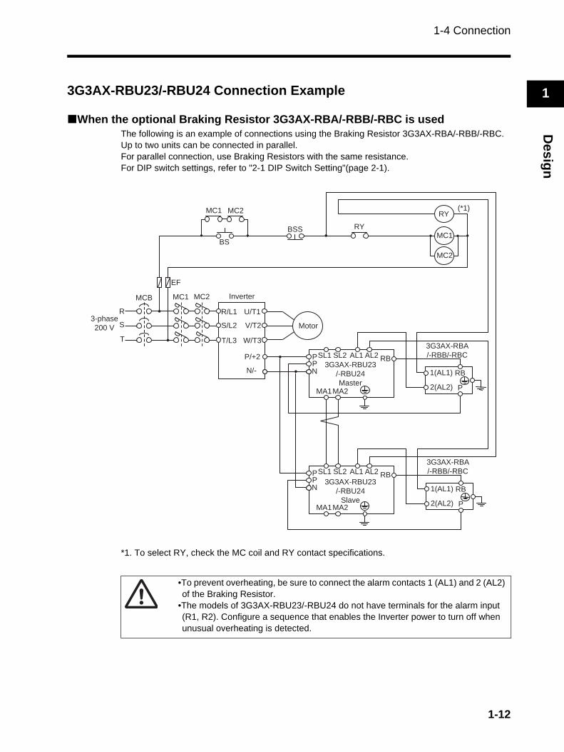
3G3AX-RBU23/-RBU24 Connection Example
When the optional Braking Resistor 3G3AX-RBA/-RBB/-RBC is usedThe following is an example of connections using the Braking Resistor 3G3AX-RBA/-RBB/-RBC.Up to two units can be connected in parallel.For parallel connection, use Braking Resistors with the same resistance.For DIP switch settings, refer to "2-1 DIP Switch Setting"(page 2-1).
*1. To select RY, check the MC coil and RY contact specifications.
R
S
T
MCB MC1
EF
PPN
SL1 SL2 AL1 AL2 RB
MA1MA2
3G3AX-RBU23
/-RBU24
Master
PPN
SL1 SL2 AL1 AL2 RB
MA1MA2
3G3AX-RBU23
/-RBU24
Slave
BS
BSS RY
RY
MC1
(*1)
R/L1
S/L2
T/L3
U/T1
V/T2
W/T3
P/+2
N/- 1(AL1)
2(AL2) P
RB
3G3AX-RBA
/-RBB/-RBC
1(AL1)
2(AL2) P
RB
3G3AX-RBA
/-RBB/-RBC
MC2
MC1 MC2
MC2
Inverter
Motor3-phase
200 V
•To prevent overheating, be sure to connect the alarm contacts 1 (AL1) and 2 (AL2) of the Braking Resistor.
•The models of 3G3AX-RBU23/-RBU24 do not have terminals for the alarm input (R1, R2). Configure a sequence that enables the Inverter power to turn off when unusual overheating is detected.
1-12
1-4 Connection
1
Des
ign
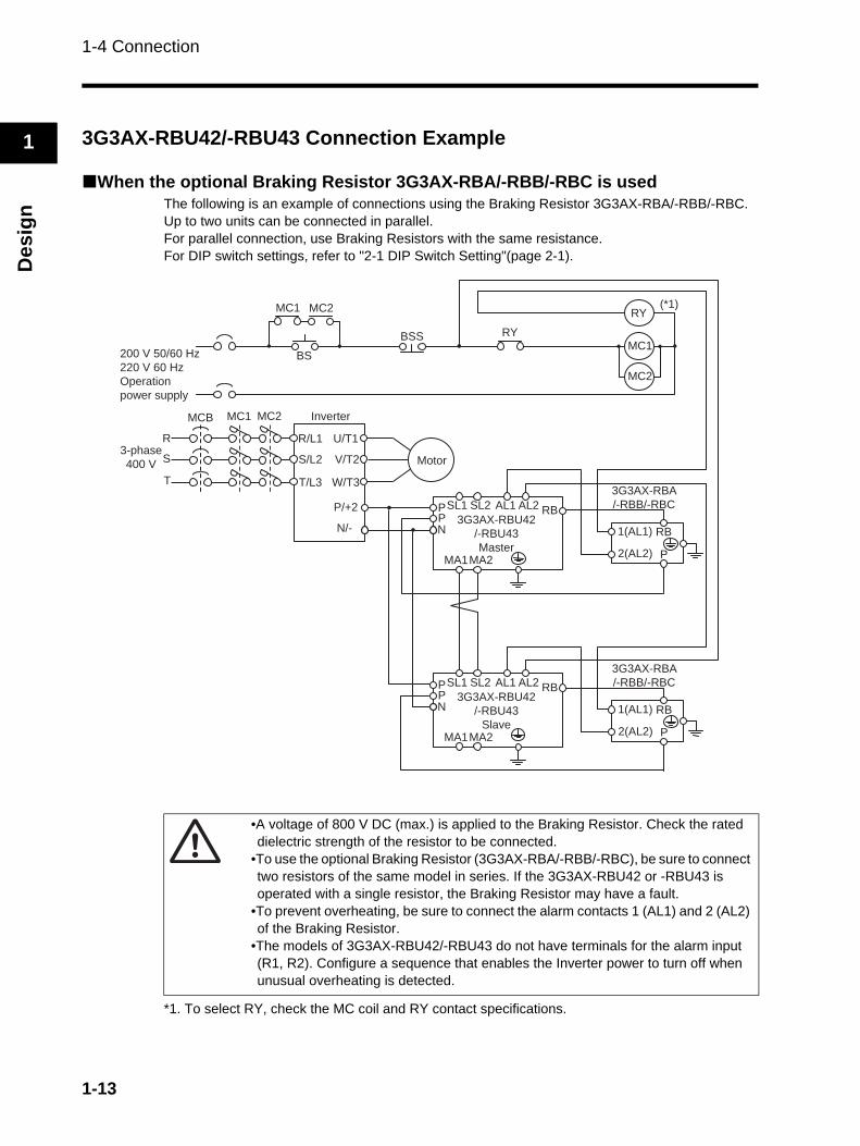
3G3AX-RBU42/-RBU43 Connection Example
When the optional Braking Resistor 3G3AX-RBA/-RBB/-RBC is usedThe following is an example of connections using the Braking Resistor 3G3AX-RBA/-RBB/-RBC.Up to two units can be connected in parallel.For parallel connection, use Braking Resistors with the same resistance.For DIP switch settings, refer to "2-1 DIP Switch Setting"(page 2-1).
*1. To select RY, check the MC coil and RY contact specifications.
R
S
T
MCB MC1
PPN
SL1 SL2 AL1 AL2 RB
MA1MA2
3G3AX-RBU42
/-RBU43
Master
PPN
SL1 SL2 AL1 AL2 RB
MA1MA2
3G3AX-RBU42
/-RBU43
Slave
BS
BSS RY
RY
MC1
(*1)
200 V 50/60 Hz
220 V 60 Hz
Operation
power supply
R/L1
S/L2
T/L3
U/T1
V/T2
W/T3
P/+2
N/- 1(AL1)
2(AL2) P
RB
3G3AX-RBA
/-RBB/-RBC
1(AL1)
2(AL2) P
RB
3G3AX-RBA
/-RBB/-RBC
MC2
MC1 MC2
MC2
Inverter
Motor3-phase
400 V
•A voltage of 800 V DC (max.) is applied to the Braking Resistor. Check the rated dielectric strength of the resistor to be connected.
•To use the optional Braking Resistor (3G3AX-RBA/-RBB/-RBC), be sure to connect two resistors of the same model in series. If the 3G3AX-RBU42 or -RBU43 is operated with a single resistor, the Braking Resistor may have a fault.
•To prevent overheating, be sure to connect the alarm contacts 1 (AL1) and 2 (AL2) of the Braking Resistor.
•The models of 3G3AX-RBU42/-RBU43 do not have terminals for the alarm input (R1, R2). Configure a sequence that enables the Inverter power to turn off when unusual overheating is detected.
1-13

Chapter 2Functions
2-1 DIP Switch Setting ........................................... 2-1
2-1
2-1 DIP Switch Setting
2
Func
tions
2Functions
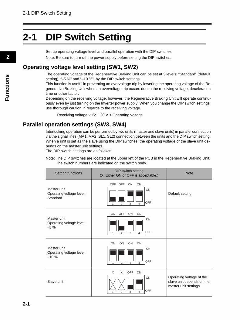
2-1 DIP Switch SettingSet up operating voltage level and parallel operation with the DIP switches.Note: Be sure to turn off the power supply before setting the DIP switches.
Operating voltage level setting (SW1, SW2)The operating voltage of the Regenerative Braking Unit can be set at 3 levels: “Standard” (default setting), “−5 %” and “−10 %”, by the DIP switch settings.This function is useful in preventing an overvoltage trip by lowering the operating voltage of the Re-generative Braking Unit when an overvoltage trip occurs due to the receiving voltage, deceleration time or other factor.Depending on the receiving voltage, however, the Regenerative Braking Unit will operate continu-ously even by just turning on the Inverter power supply. When you change the DIP switch settings, use thorough caution in regards to the receiving voltage.
Receiving voltage × √2 + 20 V < Operating voltage
Parallel operation settings (SW3, SW4)Interlocking operation can be performed by two units (master and slave units) in parallel connection via the signal lines (MA1, MA2, SL1, SL2) connection between the units and the DIP switch setting. When a unit is set as the slave using the DIP switches, the operating voltage of the slave unit de-pends on the master unit settings.The DIP switch settings are as follows:
Note: The DIP switches are located at the upper left of the PCB in the Regenerative Braking Unit. The switch numbers are indicated on the switch body.
Setting functions DIP switch setting(X: Either ON or OFF is acceptable.) Note
Master unitOperating voltage level: Standard
Default setting
Master unitOperating voltage level:−5 %
Master unitOperating voltage level:−10 %
Slave unitOperating voltage of the slave unit depends on the master unit settings.
OFF
1
OFF
2
ON
3
ON
4
ON
OFF
ON
1
OFF
2
ON
3
ON
4
ON
OFF
ON
1
ON
2
ON
3
ON
4
ON
OFF
X
1
X
2
OFF
3
ON
4
ON
OFF
Chapter 3MaintenanceOperations
3-1 Precautions before Operation......................... 3-13-2 When the Alarm Contact is Activated ............ 3-23-3 When an Inverter Overvoltage Trip Occurs ... 3-3
3-1 Precautions before Operation
3
Mai
nten
ance
Ope
ratio
ns
3Maintenance Operations
3-1 Precautions before OperationBefore operation, check the following items:
• There is no incorrect wiring.Incorrect wiring may result in damage or malfunction of the Regenerative Braking Unit.
• Check for grounding of any terminal other than the ground terminal.Improper grounding may result in damage or malfunction of the Regenerative Braking Unit.
• Check for any short-circuits caused by a wire scrap or crimp terminal left in the unit after wiring work.A short circuit may result in damage or malfunction of the Regenerative Braking Unit.
• There is no short circuit or ground fault.A short circuit or ground fault may result in damage or malfunction of the Regenerative BrakingUnit.
3-1
3-2 When the Alarm Contact is Activated
3
Maintenance O
perations
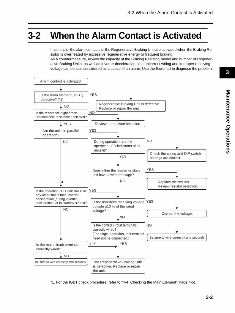
3-2 When the Alarm Contact is ActivatedIn principle, the alarm contacts of the Regenerative Braking Unit are activated when the Braking Re-sistor is overheated by excessive regenerative energy or frequent braking.As a countermeasure, review the capacity of the Braking Resistor, model and number of Regener-ative Braking Units, as well as Inverter deceleration time. Incorrect wiring and improper receiving voltage can be also considered as a cause of an alarm. Use the flowchart to diagnose the problem:
*1. For the IGBT check procedure, refer to "4-4 Checking the Main Element"(Page 4-5).
Alarm contact is activated.
Is the main element (IGBT)
defective? (*1)
Is the resistance higher than
"connectable resistance" selected?
Are the units in parallel
operation?
NO
YES
Regenerative Braking Unit is defective.
Replace or repair the unit.
Review the resistor selection.
During operation, are the
operation LED indicators of all
units lit?Check the wiring and DIP switch
settings are correct.
Does either the master or slave
unit have a wire breakage?
Replace the resistor.
Review resistor selection.
Is the operation LED indicator lit in
any other status than Inverter
deceleration (during Inverter
acceleration, or in standby status)? Is the Inverter's receiving voltage
outside ±10 % of the rated
voltage?Correct the voltage.
Is the control circuit terminals
correctly wired?
(For single operation, this terminal
need not be connected.) Be sure to wire correctly and securely.
Is the main circuit terminals
correctly wired?
The Regenerative Braking Unit
is defective. Replace or repair
the unit.
NO
Be sure to wire correctly and securely.
YES YES
NO
YES
NO
NO
YES
YES
NO
NO
YES
YES
NO
YES
NO
3-2
3-3 When an Inverter Overvoltage Trip Occurs
3
Mai
nten
ance
Ope
ratio
ns
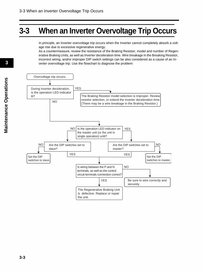
3-3 When an Inverter Overvoltage Trip OccursIn principle, an Inverter overvoltage trip occurs when the Inverter cannot completely absorb a volt-age rise due to excessive regenerative energy.As a countermeasure, review the resistance of the Braking Resistor, model and number of Regen-erative Braking Units, as well as Inverter deceleration time. Wire breakage in the Breaking Resistor, incorrect wiring, and/or improper DIP switch settings can be also considered as a cause of an In-verter overvoltage trip. Use the flowchart to diagnose the problem:
Overvoltage trip occurs.
During Inverter deceleration,
is the operation LED indicator
lit?
NO
The Braking Resistor model selection is improper. Review
resistor selection, or extend the inverter deceleration time.
(There may be a wire breakage in the Braking Resistor.)
Is the operation LED indicator on
the master unit (or the unit in
single operation) unlit?
Set the DIP
switches to master.
Is wiring between the P and N
terminals, as well as the control
circuit terminals connection correct?
Be sure to wire correctly and
securely.
The Regenerative Braking Unit
is defective. Replace or repair
the unit.
YES
NO
NO
YES
YES
Are the DIP switches set to
master?
Are the DIP switches set to
slave?
Set the DIP
switches to slave.
NONO
YES
YES
3-3

Chapter 4Inspection andMaintenance
4-1 Inspection and Maintenance ........................... 4-14-2 Daily Inspection and Periodic Inspection ...... 4-24-3 Megger Test ...................................................... 4-44-4 Checking the Main Element ............................ 4-54-5 Capacitor Life Curve ........................................ 4-6
4-1 Inspection and Maintenance
4
Insp
ectio
n an
d M
aint
enan
ce
4Inspection and Maintenance
4-1 Inspection and Maintenance
Daily InspectionBasically, check the following during operation.
1) There are no errors in the installation environment.2) There are no errors in the cooling system.3) There are no abnormal vibrations or sounds.4) There are no abnormal overheat or discoloration.5) There are no abnormal odors.
CleaningAlways keep the Regenerative Braking Unit clean for operation.Lightly remove any dirt with a soft cloth moistened with a neutral detergent.
Note: Do not use such solutions as acetone, benzene, toluene, or alcohol for cleaning. Doing so may cause the Regenerative Braking Unit surface to dissolve or its coating to come off.
Periodic InspectionCheck the parts that cannot be checked without stopping operation, as well as those that require periodic inspection.
1) Check that there are no errors in the cooling system (Clean the air filter).2) Check that all parts that need tightening are secure (Screws and bolts may become loose because
of vibration or temperature change).3) Check that there is no corrosion or damage to the conductors and/or insulators.4) Measurement of insulation resistance5) Check and replace the capacitor.
4-1
4-2 Daily Inspection and Periodic Inspection
4
Inspection and Maintenance
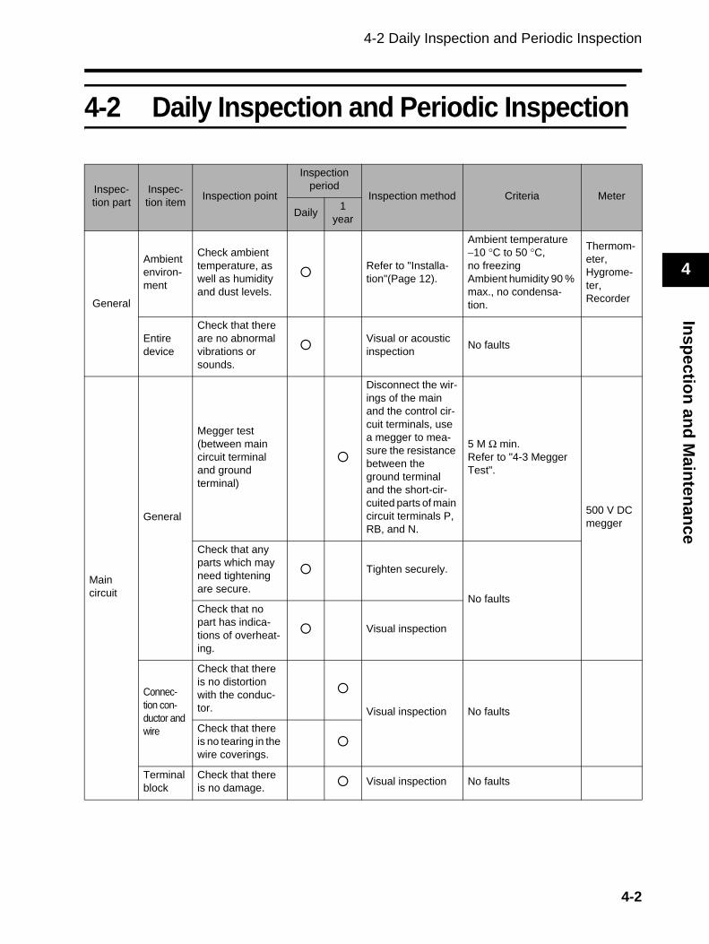
4-2 Daily Inspection and Periodic Inspection
Inspec-tion part
Inspec-tion item Inspection point
Inspection period
Inspection method Criteria MeterDaily 1
year
General
Ambient environ-ment
Check ambient temperature, as well as humidity and dust levels.
Refer to "Installa-tion"(Page 12).
Ambient temperature −10 °C to 50 °C, no freezingAmbient humidity 90 % max., no condensa-tion.
Thermom-eter,Hygrome-ter,Recorder
Entire device
Check that there are no abnormal vibrations or sounds.
Visual or acoustic inspection No faults
Maincircuit
General
Megger test(between main circuit terminal and ground terminal)
Disconnect the wir-ings of the main and the control cir-cuit terminals, use a megger to mea-sure the resistance between the ground terminal and the short-cir-cuited parts of main circuit terminals P, RB, and N.
5 M Ω min.Refer to "4-3 Megger Test".
500 V DC megger
Check that any parts which may need tightening are secure.
Tighten securely.
No faultsCheck that no part has indica-tions of overheat-ing.
Visual inspection
Connec-tion con-ductor and wire
Check that there is no distortion with the conduc-tor. Visual inspection No faultsCheck that there is no tearing in the wire coverings.
Terminal block
Check that there is no damage. Visual inspection No faults
4-2
4-2 Daily Inspection and Periodic Inspection
4
Insp
ectio
n an
d M
aint
enan
ce
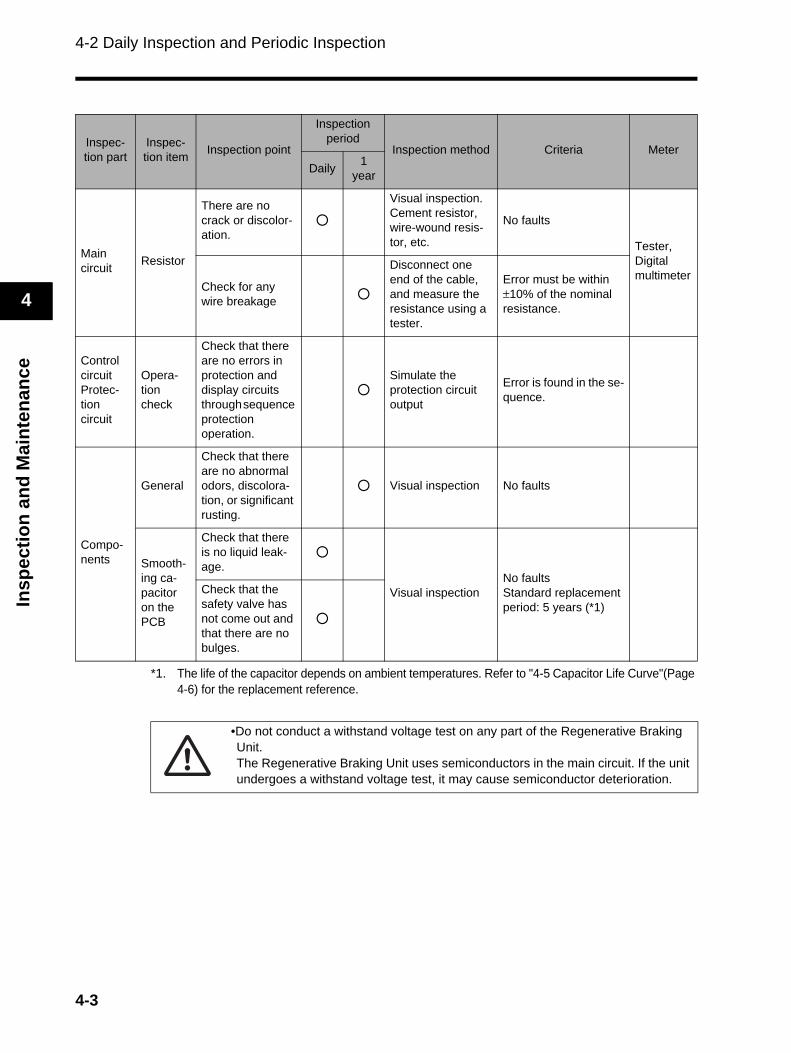
*1. The life of the capacitor depends on ambient temperatures. Refer to "4-5 Capacitor Life Curve"(Page 4-6) for the replacement reference.
Inspec-tion part
Inspec-tion item Inspection point
Inspection period
Inspection method Criteria MeterDaily 1
year
Main circuit Resistor
There are no crack or discolor-ation.
Visual inspection. Cement resistor, wire-wound resis-tor, etc.
No faults
Tester, Digital multimeter
Check for any wire breakage
Disconnect one end of the cable, and measure the resistance using a tester.
Error must be within ±10% of the nominal resistance.
Control circuitProtec-tion circuit
Opera-tion check
Check that there are no errors in protection and display circuits through sequence protection operation.
Simulate the protection circuit output
Error is found in the se-quence.
Compo-nents
General
Check that there are no abnormal odors, discolora-tion, or significant rusting.
Visual inspection No faults
Smooth-ing ca-pacitor on the PCB
Check that there is no liquid leak-age.
Visual inspectionNo faultsStandard replacement period: 5 years (*1)
Check that the safety valve has not come out and that there are no bulges.
•Do not conduct a withstand voltage test on any part of the Regenerative Braking Unit.The Regenerative Braking Unit uses semiconductors in the main circuit. If the unit undergoes a withstand voltage test, it may cause semiconductor deterioration.
4-3
4-3 Megger Test
4
Inspection and Maintenance
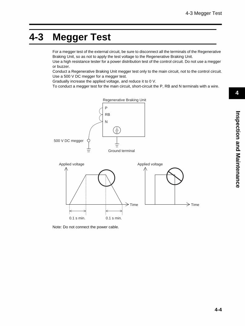
4-3 Megger TestFor a megger test of the external circuit, be sure to disconnect all the terminals of the Regenerative Braking Unit, so as not to apply the test voltage to the Regenerative Braking Unit.Use a high resistance tester for a power distribution test of the control circuit. Do not use a megger or buzzer.Conduct a Regenerative Braking Unit megger test only to the main circuit, not to the control circuit.Use a 500 V DC megger for a megger test.Gradually increase the applied voltage, and reduce it to 0 V.To conduct a megger test for the main circuit, short-circuit the P, RB and N terminals with a wire.
Note: Do not connect the power cable.
Regenerative Braking Unit
P
RB
N
500 V DC megger
Ground terminal
Applied voltage Applied voltage
0.1 s min. 0.1 s min.
Time Time
4-4
4-4 Checking the Main Element
4
Insp
ectio
n an
d M
aint
enan
ce
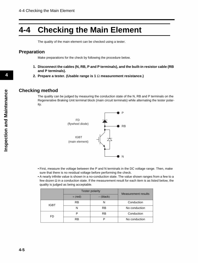
4-4 Checking the Main ElementThe quality of the main element can be checked using a tester.
PreparationMake preparations for the check by following the procedure below.
1. Disconnect the cables (N, RB, P and P terminals), and the built-in resistor cable (RB and P terminals).
2. Prepare a tester. (Usable range is 1 Ω measurement resistance.)
Checking methodThe quality can be judged by measuring the conduction state of the N, RB and P terminals on the Regenerative Braking Unit terminal block (main circuit terminals) while alternating the tester polar-ity.
• First, measure the voltage between the P and N terminals in the DC voltage range. Then, make sure that there is no residual voltage before performing the check.
• A nearly infinite value is shown in a no-conduction state. The value shown ranges from a few to a few dozen Ω in a conduction state. If the measurement result for each item is as listed below, the quality is judged as being acceptable.
Tester polarityMeasurement results
+ (red) − (black)
IGBTRB N Conduction
N RB No conduction
FDP RB Conduction
RB P No conduction
FD
(flywheel diode)
IGBT
(main element)
P
RB
N
4-5
4-5 Capacitor Life Curve
4
Inspection and Maintenance
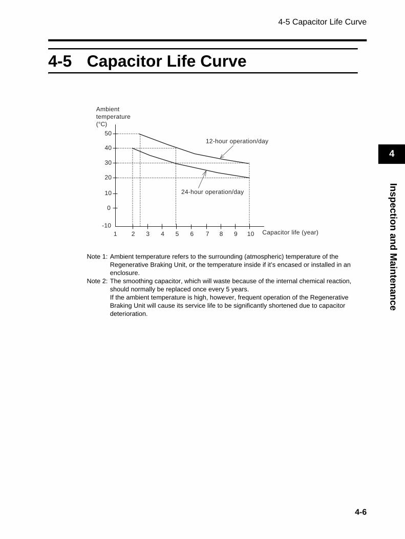
4-5 Capacitor Life Curve
Note 1: Ambient temperature refers to the surrounding (atmospheric) temperature of the Regenerative Braking Unit, or the temperature inside if it’s encased or installed in an enclosure.
Note 2: The smoothing capacitor, which will waste because of the internal chemical reaction, should normally be replaced once every 5 years.If the ambient temperature is high, however, frequent operation of the Regenerative Braking Unit will cause its service life to be significantly shortened due to capacitor deterioration.
10
20
30
40
1
50
0
-10
2 4 5 6 7 8 9 103 Capacitor life (year)
12-hour operation/day
24-hour operation/day
Ambient
temperature
(°C)
4-6
Chapter 5Specifications
5-1 Standard Specification List............................. 5-15-2 Dimensional Drawing....................................... 5-5
5-1 Standard Specification List
5
Spec
ifica
tions
5Specifications
5-1 Standard Specification List
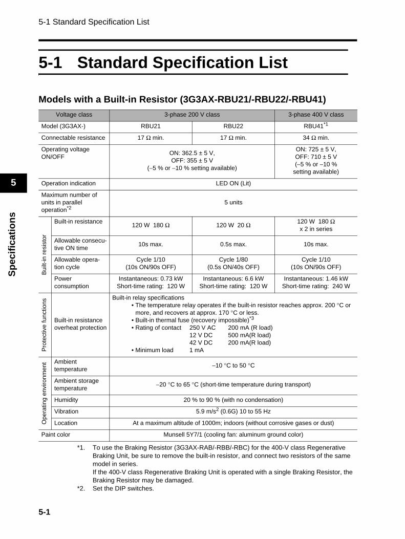
Models with a Built-in Resistor (3G3AX-RBU21/-RBU22/-RBU41)
*1. To use the Braking Resistor (3G3AX-RAB/-RBB/-RBC) for the 400-V class Regenerative Braking Unit, be sure to remove the built-in resistor, and connect two resistors of the same model in series.If the 400-V class Regenerative Braking Unit is operated with a single Braking Resistor, the Braking Resistor may be damaged.
*2. Set the DIP switches.
Voltage class 3-phase 200 V class 3-phase 400 V class
Model (3G3AX-) RBU21 RBU22 RBU41*1
Connectable resistance 17 Ω min. 17 Ω min. 34 Ω min.
Operating voltageON/OFF ON: 362.5 ± 5 V,
OFF: 355 ± 5 V(−5 % or −10 % setting available)
ON: 725 ± 5 V, OFF: 710 ± 5 V(−5 % or −10 %
setting available)
Operation indication LED ON (Lit)
Maximum number of units in parallel operation*2
5 units
Built
-in re
sist
or
Built-in resistance 120 W 180 Ω 120 W 20 Ω 120 W 180 Ωx 2 in series
Allowable consecu-tive ON time 10s max. 0.5s max. 10s max.
Allowable opera-tion cycle
Cycle 1/10(10s ON/90s OFF)
Cycle 1/80(0.5s ON/40s OFF)
Cycle 1/10(10s ON/90s OFF)
Power consumption
Instantaneous: 0.73 kWShort-time rating: 120 W
Instantaneous: 6.6 kWShort-time rating: 120 W
Instantaneous: 1.46 kWShort-time rating: 240 W
Prot
ectiv
e fu
nctio
ns
Built-in resistance overheat protection
Built-in relay specifications• The temperature relay operates if the built-in resistor reaches approx. 200 °C or
more, and recovers at approx. 170 °C or less.• Built-in thermal fuse (recovery impossible)*3• Rating of contact 250 V AC 200 mA (R load)
12 V DC 500 mA(R load)42 V DC 200 mA(R load)
• Minimum load 1 mA
Ope
ratin
g en
viro
nmen
t Ambient temperature −10 °C to 50 °C
Ambient storage temperature −20 °C to 65 °C (short-time temperature during transport)
Humidity 20 % to 90 % (with no condensation)
Vibration 5.9 m/s2 (0.6G) 10 to 55 Hz
Location At a maximum altitude of 1000m; indoors (without corrosive gases or dust)
Paint color Munsell 5Y7/1 (cooling fan: aluminum ground color)
5-1
5-1 Standard Specification List
5
Specifications
*3. The built-in resistor has a thermal fuse.If the alarm terminal is not connected, the fuse may blow out in order to prevent the resistor from burning due to overheating.If the fuse blows out, the built-in resistor must be replaced.
5-2
5-1 Standard Specification List
5
Spec
ifica
tions
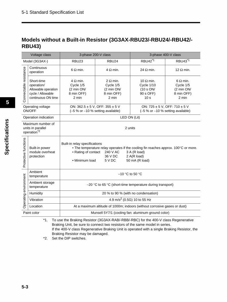
Models without a Built-in Resistor (3G3AX-RBU23/-RBU24/-RBU42/-RBU43)
*1. To use the Braking Resistor (3G3AX-RAB/-RBB/-RBC) for the 400-V class Regenerative Braking Unit, be sure to connect two resistors of the same model in series.If the 400-V class Regenerative Braking Unit is operated with a single Braking Resistor, the Braking Resistor may be damaged.
*2. Set the DIP switches.
Voltage class 3-phase 200-V class 3-phase 400-V class
Model (3G3AX-) RBU23 RBU24 RBU42*1 RBU43*1
Con
nect
able
resi
stan
ce Continuous operation 6 Ω min. 4 Ω min. 24 Ω min. 12 Ω min.
Short-time operation/Allowable operation cycle / Allowable continuous ON time
4 Ω min.Cycle 1/5
(2 min ON/8 min OFF)
2 min
2 Ω min.Cycle 1/5
(2 min ON/8 min OFF)
2 min
10 Ω min.Cycle 1/10(10 s ON/90 s OFF)
10 s
6 Ω min.Cycle 1/5
(2 min ON/8 min OFF)
2 min
Operating voltageON/OFF
ON: 362.5 ± 5 V, OFF: 355 ± 5 V(−5 % or −10 % setting available)
ON: 725 ± 5 V, OFF: 710 ± 5 V(−5 % or −10 % setting available)
Operation indication LED ON (Lit)
Maximum number of units in parallel operation*2
2 units
Pro
tect
ive
func
tions
Built-in power module overheat protection
Built-in relay specifications• The temperature relay operates if the cooling fin reaches approx. 100°C or more.• Rating of contact 240 V AC 3 A (R load)
36 V DC 2 A(R load)• Minimum load 5 V DC 50 mA (R load)
Ope
ratin
g en
viro
nmen
t Ambient temperature −10 °C to 50 °C
Ambient storage temperature −20 °C to 65 °C (short-time temperature during transport)
Humidity 20 % to 90 % (with no condensation)
Vibration 4.9 m/s2 (0.5G) 10 to 55 Hz
Location At a maximum altitude of 1000m; indoors (without corrosive gases or dust)
Paint color Munsell 5Y7/1 (cooling fan: aluminum ground color)
5-3
5-1 Standard Specification List
5
Specifications
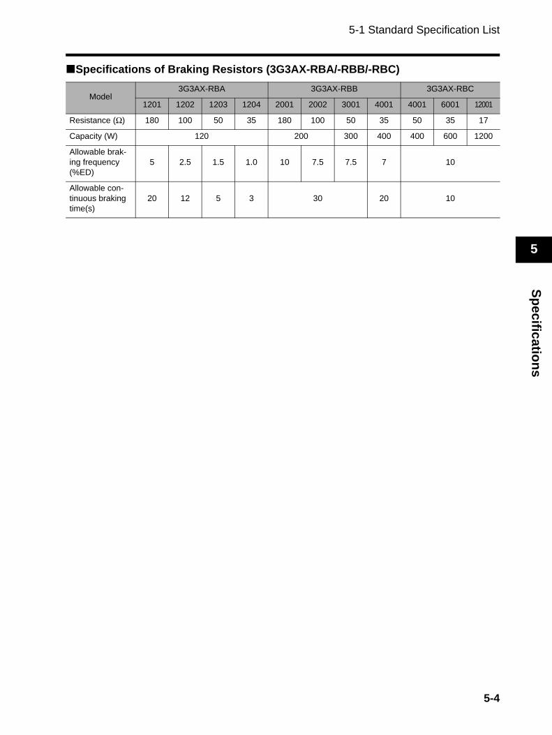
Specifications of Braking Resistors (3G3AX-RBA/-RBB/-RBC)
Model3G3AX-RBA 3G3AX-RBB 3G3AX-RBC
1201 1202 1203 1204 2001 2002 3001 4001 4001 6001 12001
Resistance (Ω) 180 100 50 35 180 100 50 35 50 35 17
Capacity (W) 120 200 300 400 400 600 1200
Allowable brak-ing frequency (%ED)
5 2.5 1.5 1.0 10 7.5 7.5 7 10
Allowable con-tinuous braking time(s)
20 12 5 3 30 20 10
5-4
5-2 Dimensional Drawing
5
Spec
ifica
tions
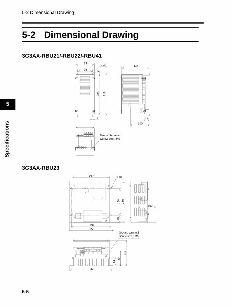
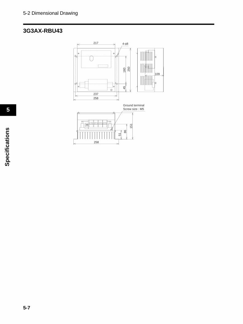
5-2 Dimensional Drawing
3G3AX-RBU21/-RBU22/-RBU41
3G3AX-RBU23
95
5
100
35
145
5208
218
75
2-φ5
Ground terminal
Screw size : M5
217
109
237
258
258
160
45
51
86
151
250
Ground terminal
Screw size : M5
4-φ8
5-5
5-2 Dimensional Drawing
5
Specifications
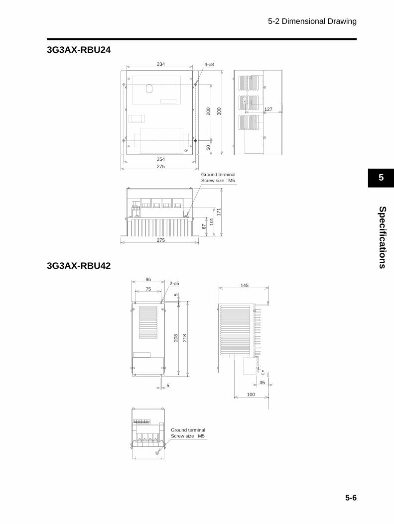
3G3AX-RBU24
3G3AX-RBU42
234
20
05
06
7 10
1
17
13
00
254
127
275
275
4-φ8
Ground terminal
Screw size : M5
95
145
35
100
5
75
5208
218
2-φ5
Ground terminal
Screw size : M5
5-6
5-2 Dimensional Drawing
5
Spec
ifica
tions
3G3AX-RBU43
217
16
04
5
51 8
6
15
12
50
237
258
258
109
Ground terminal
Screw size : M5
4-φ8
5-7

Authorized Distributor:
In the interest of product improvement, specifications are subject to change without notice.
Cat. No. I563-E1-02OMRON Industrial Automation Global: www.ia.omron.com
OMRON CorporationIndustrial Automation Company
Regional HeadquartersOMRON EUROPE B.V.Wegalaan 67-69-2132 JD HoofddorpThe NetherlandsTel: (31)2356-81-300/Fax: (31)2356-81-388
OMRON ELECTRONICS LLCOne Commerce Drive Schaumburg,IL 60173-5302 U.S.A.Tel: (1) 847-843-7900/Fax: (1) 847-843-7787
OMRON ASIA PACIFIC PTE. LTD.No. 438A Alexandra Road # 05-05/08 (Lobby 2), Alexandra Technopark, Singapore 119967Tel: (65) 6835-3011/Fax: (65) 6835-2711
OMRON (CHINA) CO., LTD.Room 2211, Bank of China Tower, 200 Yin Cheng Zhong Road, PuDong New Area, Shanghai, 200120, ChinaTel: (86) 21-5037-2222/Fax: (86) 21-5037-2200
Control Devices Division H.Q.Motion Control DivisionShiokoji Horikawa, Shimogyo-ku,Kyoto, 600-8530 JapanTel: (81) 75-344-7173/Fax: (81) 75-344-71492-2-1 Nishikusatsu, Kusatsu-shi, Shiga, 525-0035 JapanTel: (81) 77-565-5223/Fax: (81) 77-565-5568