3D Coordinates & Transformationsstanley.gatech.edu/wp-content/uploads/sites/466/... · 3D graphics...
37
3D Coordinates & Transformations Prof. Aaron Lanterman (Based on slides by Prof. Hsien-Hsin Sean Lee) School of Electrical and Computer Engineering Georgia Institute of Technology
Transcript of 3D Coordinates & Transformationsstanley.gatech.edu/wp-content/uploads/sites/466/... · 3D graphics...

3D Coordinates & Transformations
Prof. Aaron Lanterman (Based on slides by Prof. Hsien-Hsin Sean Lee) School of Electrical and Computer Engineering
Georgia Institute of Technology

2
3D graphics rendering pipeline (1)
• Geometry Pipeline – Processing Vertices – Mainly floating-point operations
• Rasterization Pipeline – Processing Pixels – Mainly dealing with Integer operations
Geometry Processing
x y
z
x y
z
x y
z
x y
z
x y
z
x
y
Rasterization Processing
x
y

3
3D graphics rendering pipeline (2)
• Geometry Pipeline – Processing Vertices – Mainly floating-point operations
• Rasterization Pipeline – Processing Pixels – Mainly dealing with Integer operations – MMX was originally designed to accelerate
this type of functionality
Geometry Processing
x y
z
x y
z
x y
z
x y
z
x y
z
x
y
Rasterization Processing
x
y
MMX ISA

4
3D graphics rendering pipeline (3)
• Geometry Pipeline – Processing Vertices – Mainly floating-point operations – SSE/SSE2 were designed for this part
• Rasterization Pipeline – Processing Pixels – Mainly dealing with Integer operations – MMX was originally designed to accelerate
this type of functionality
Geometry Processing
x y
z
x y
z
x y
z
x y
z
x y
z
x
y
Rasterization Processing
x
y
MMX ISA SSE/SSE2 ISA
5
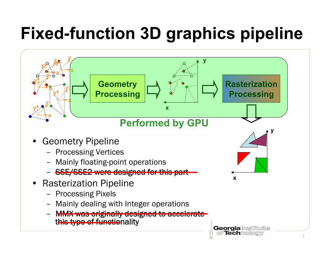
Fixed-function 3D graphics pipeline
• Geometry Pipeline – Processing Vertices – Mainly floating-point operations – SSE/SSE2 were designed for this part
• Rasterization Pipeline – Processing Pixels – Mainly dealing with Integer operations – MMX was originally designed to accelerate
this type of functionality
Geometry Processing
x y
z
x y
z
x y
z
x y
z
x y
z
x
y
Rasterization Processing
x
y Performed by GPU

6
3D Coord: Math textbooks use z-up
+y
+x
+z
Z-up, Right-Handed System
7
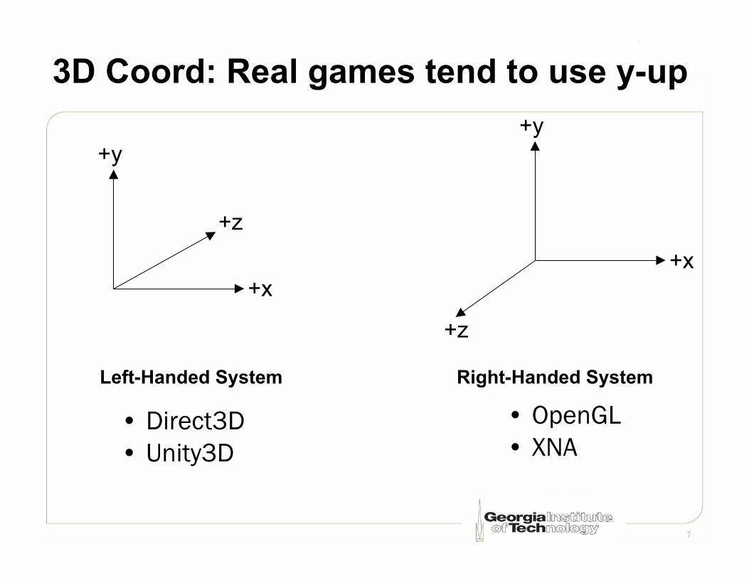
3D Coord: Real games tend to use y-up
+z
+x
+y
Left-Handed System
+z
+x
+y
Right-Handed System • OpenGL • XNA
• Direct3D • Unity3D

8
X-Y natural for screen coordinates
+z (away from the viewer)
+x
+y
Left-Handed System
+z (toward the viewer)
+x
+y
Right-Handed System • OpenGL • XNA
• Direct3D • Unity3D

9
Some use Z-up for world coordinates
+y
+x
+z
Left-Handed System
+y
+x
+z
Right-Handed System
• Z-up, LHS: Unreal • Z-up, RHS: Quake/Radiant, Source/Hammer, C4 Engine • Nearly everything still uses Y-up for screen coordinates!

10
Another view
+y
+x
+z
Left-Handed System Right-Handed System
+x
+y
+z
• Quake/Radiant • Source/Hammer • C4 Engine
• Unreal

11
3D “object” modeling software
3D Studio Max, Blender
+z
+x
+y
Right-Handed System
Maya, Milkshape
+y
+x
+z
Right-Handed System

12
Geometry format – vertex coordinates
(X1, Y1, Z1)
(X2, Y2, Z2)
(X3, Y3, Z3)
+Z
+X
+Y
X1
Z1
Y1

13
Geometry format ─ vertex normals
(NX1, NY1, NZ1)
(NX2, NY2, NZ2)
(NX3, NY3, NZ3)
+Z
+X
+Y

14
Geometry format ─ vertex colors
(R1, G1, B1, A1)
(R2, G2, B2, A2)
(R3, B3, B3, G3)
+Z
+X
+Y

15
Triangle-based geometry representation
V1 V2
V3 V4
V5
V6 V7
V8
V9
Triangle List (note the vertex order)
V5 V4
V3
V2
V1
Triangle Strip
V5 V4
V1
V3
V2
Triangle Fan
Careful!

16
Specifying a 3D object (1)
V1
V2 V3
V4
V5
V6 V7 Triangle list {v1, v3, v2}, {v1, v5, v3}, {v5, v6, v3}, {v4, v3, v6}, {v1, v7, v6}, {v1, v6, v5}
Triangle strip {v5, v3, v1, v2}, {v5, v6, v3, v4}, {v7, v6, v1, v5}
• Vertex ordering is critical when culling mode enabled • We will discuss normal computation later

17
V8
Specifying a 3D object (2)
• Vertex ordering is critical when culling mode enabled • We will discuss normal computation later
V1
V2 V3
V4
V6 V7 Triangle list {v1, v2, v7}, {v2, v8, v7}, {v2, v3, v4}, {v2, v4, v8}, {v4, v7, v8}, {v4, v6, v7}
Triangle strip {v1, v2, v7, v8}, {v3, v4, v2, v8}, {v6, v7, v4, v8}

18
3D rendering pipeline
Clipp
ing
Persp
ectiv
e Divi
de
View
port
Tran
sform
Raste
rizati
on
Proje
ction
Tran
sform
Wor
ld Tr
ansfo
rm
View
Tran
sform
Lighti
ng
Back
face C
ulling

19
Transformation pipeline • World Transformation
– Model coordinates à World coordinates
• View Transformation – World coordinates à Camera space
• Projection Transformation – Camera space à View plane
• These are a series of matrix multiplications

20
World transformation
• Translation • Rotation • Scaling
+x
+z
+y
World origin
World Coordinates
Local model coordinates
Local model coordinates

21
View transformation
+x
+z
+y
World origin
World Coordinates
+y
+x
+z
• Camera position • Look vector

22
Projection transformation • Set up camera internals
• Set up – Field of View (FOV) – View frustum – View planes
• Will discuss in the next lecture

23
Homogeneous coordinates • Enable all transformations to be done by
“multiplication” – Primarily for translation (see next few slides)
• Add one coordinate (w) to a 3D vector
• Each vertex has [x, y, z, w] – w will be useful for perspective projection – w should be 1 in a Cartesian coordinate system

24
Transformation 1: translation (Offset)
+x
+z
+y
+x
+z
+y
(x, y, z)
(xt, yt, zt)

25
Translation matrix
[xt,yt,zt,1]= [x,y,z,1]⋅
1 0 0 00 1 0 00 0 1 0Tx Ty Tz 1
"
#
$$$$
%
&
''''
• Example of a row-coordinate convention • Direct3D, XNA, HLSL/Cg use row coordinates • OpenGL & non-graphics world uses column
coordinates

26
Transformation 2: scaling
+x
+z
+y
+x
+z
+y

27
Scaling matrix
[xs,ys,zs,1]= [x,y,z,1]⋅
Sx 0 0 00 Sy 0 00 0 Sz 00 0 0 1
"
#
$$$$
%
&
''''
28
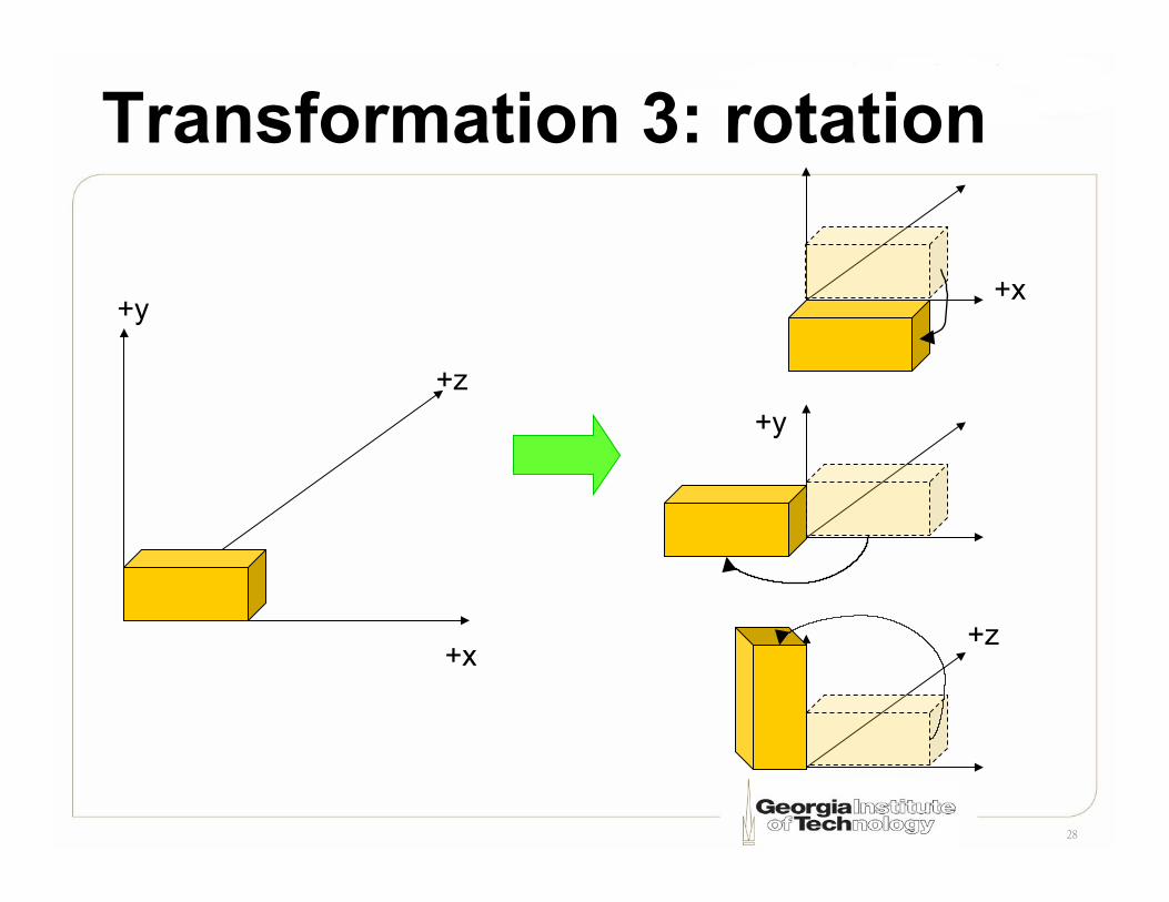
Transformation 3: rotation
+x
+z
+y
+y
+x
+z

29
2D rotation
+x
+y
+x
+y
θ
(x, y)
(x’, y’)
+x
+y
(x, y) θ ϕ
⎥⎥⎥
⎦
⎤
⎢⎢⎢
⎣
⎡
−⋅=
1000cossin0sincos
]y,1x,[],1y',x'[ θθθθ
Rotate along which axis?

30
3D rotation matrix (LHS)
⎥⎥⎥⎥
⎦
⎤
⎢⎢⎢⎢
⎣
⎡
−⋅=
1000010000cossin00sincos
]z,1y,x,[],1z',y',x'[θθθθ
Rotation along Z axis
⎥⎥⎥⎥
⎦
⎤
⎢⎢⎢⎢
⎣
⎡ −
⋅=
10000cos0sin00100sin0cos
]z,1y,x,[],1z',y',x'[θθ
θθ
Rotation along Y axis
⎥⎥⎥⎥
⎦
⎤
⎢⎢⎢⎢
⎣
⎡
−⋅=
10000cossin00sincos00001
]z,1y,x,[],1z',y',x'[θθθθ
Rotation along X axis

31
Non-commutative property (1)
1. Counter-clockwise 90o along y 2. Clockwise 90o along x
+x
+z
+y
�
� +x
+z
+y
1. Clockwise 90o along x 2. Counter-clockwise 90o along y
�
�
32
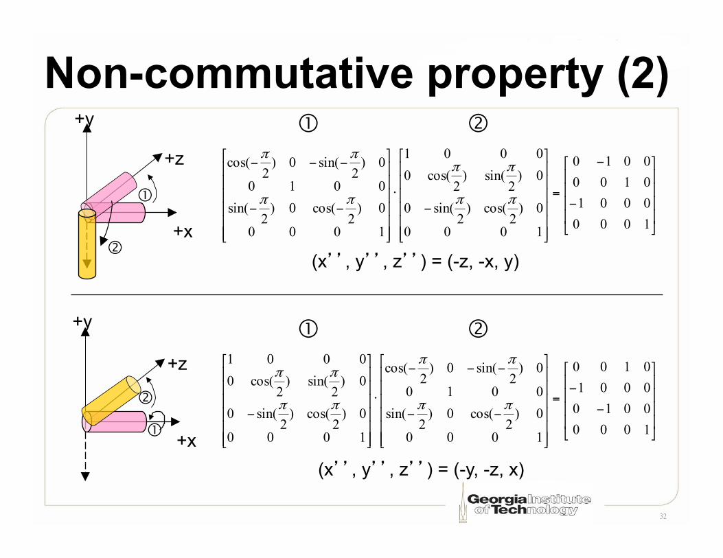
Non-commutative property (2)
+x
+z
+y
�
�
+x
+z
+y
�
�
⎥⎥⎥⎥
⎦
⎤
⎢⎢⎢⎢
⎣
⎡
−
−
=
⎥⎥⎥⎥⎥⎥
⎦
⎤
⎢⎢⎢⎢⎢⎢
⎣
⎡
−⋅
⎥⎥⎥⎥⎥⎥
⎦
⎤
⎢⎢⎢⎢⎢⎢
⎣
⎡
−−
−−−
1000000101000010
1000
0)2
cos()2
sin(0
0)2
sin()2
cos(00001
1000
0)2
cos(0)2
sin(0010
0)2
sin(0)2
cos(
ππ
ππ
ππ
ππ
� �
⎥⎥⎥⎥
⎦
⎤
⎢⎢⎢⎢
⎣
⎡
−
−=
⎥⎥⎥⎥⎥⎥
⎦
⎤
⎢⎢⎢⎢⎢⎢
⎣
⎡
−−
−−−
⋅
⎥⎥⎥⎥⎥⎥
⎦
⎤
⎢⎢⎢⎢⎢⎢
⎣
⎡
−1000001000010100
1000
0)2
cos(0)2
sin(0010
0)2
sin(0)2
cos(
1000
0)2
cos()2
sin(0
0)2
sin()2
cos(00001
ππ
ππ
ππ
ππ
� �
(x’’, y’’, z’’) = (-z, -x, y)
(x’’, y’’, z’’) = (-y, -z, x)

33
Non-commutative property (3)
1. Translation by (x, y, z) 2. Scale by 2 times
+x
+z
+y
1. Scale by 2 times 2. Translation by (x, y, z)
�
�
+x
+z
+y
� �

34
Non-commutative property (4)
+x
+z
+y
�
�
+x
+z
+y
� �
⎥⎥⎥⎥
⎦
⎤
⎢⎢⎢⎢
⎣
⎡
=
⎥⎥⎥⎥
⎦
⎤
⎢⎢⎢⎢
⎣
⎡
⋅
⎥⎥⎥⎥
⎦
⎤
⎢⎢⎢⎢
⎣
⎡
1000000000
1000000000000
1010000100001
SzTzSyTySxTxSz
SySx
SzSy
Sx
TzTyTx
� �
(x’’, y’’, z’’) = (x*Sx+Sx*Tx, y*Sy+Sy*Ty, z*Sz+Sz*Tz)
⎥⎥⎥⎥
⎦
⎤
⎢⎢⎢⎢
⎣
⎡
=
⎥⎥⎥⎥
⎦
⎤
⎢⎢⎢⎢
⎣
⎡
⋅
⎥⎥⎥⎥
⎦
⎤
⎢⎢⎢⎢
⎣
⎡
1000000000
1010000100001
1000000000000
TzTyTxSz
SySx
TzTyTxSz
SySx
� �
(x’’, y’’, z’’) = (x*Sx+Tx, y*Sy+Ty, z*Sz+Tz)
Offsets were scaled as well

35
Non-commutative property (5)
• Ordering matters !
• Be careful when performing matrix multiplication

36
View transformation revisited
+x
+z
+y
World origin
World Coordinates
+y
+x
+z
• Camera position • Look vector

37
Specifying the view transformation • Most commonly parameterized by:
– Position of camera – Position of point to look at – Vector indicating “up” direction of camera
• In Direct3D: D3DXMatrixLookAtLH!– D3D uses a LHS, but also have D3DXMatrixLookAtRH
• In XNA: Matrix.CreateLookAt (RHS) • In OpenGL: gluLookAt (RHS) • Can also build a rotation+translation matrix as if the
camera was an object in scene, then take the inverse of that matrix
msdn.microsoft.com/en-us/library/bb205342(VS.85).aspx msdn.microsoft.com/en-us/library/bb205343(VS.85).aspx