3ARDAR PATEL COLLEGE OF ENGIN
20
Bharatiya Vidya Bhavan's 3ARDAR PATEL COLLEGE OF ENGIN (Government Aided Autonomous Institute) Munshi Nagar, Andheri (W) Mumbai — 400058 END SEMESTER - January 2020 Re-Examination-i Q 2_4?.7 Pro - ral.1: B. Tech. (Mechanical Engineering) Duration: 03 firs Course Code: PC-BTM503 Maximum Points: 100 Course Name: Mechatronics Semester: V Notes: 1. Question Number 1 is compulsory 2. Attempt any four questions from remaining (Q. No. 2 to Q. No. 7) 3. If necessary assume suitable data with justification 4. Draw neat labeled sketches wherever Q. No. -. Questions Points CO BL PI 1(A) Draw Bode plot and comment on stability for 200(S + 5) G (s)H (s) = 10 4 4 3.3.2 5(5 + 1)(S + 100) 1(B) Using Routh's Criteria find stability of the control system having characteristics equation 56 + 4 S5 + 3 S4 — 16 S2 — 64 S — 48 =0 10 3 3 1.3.1 2(A) Find root locus for K (S + 5) G (s)H = 10 4 1 2.3.1 (s) S (S + 20) 2 (B) Explain architecture of 8051 microcontroller with neat block and pin diagram 10 1 2 1.3.2 3(A) Two double acting pneumatic cylinders A, B are selected for an industrial application. The sequence of movement for cylinder is as indicated below 10 3 4 3.2.2 - A+ Delay B+ B- A- Design pure pneumatic circuit considering 4/2 air-air operated final directional control valves for cylinder A and B. 3 (B) Explain execution of cloth washing on automatic washing Machine system in the form of (i)Information Systems (ii) Mechanical Systems (iii) Electrical systems (iv) Sensors and Actuators 10 1 3 1.3.1 4(A) Draw Polar plot and comment on stability of system for 100 G (s)H = 10 4 5 3.3.1 (s) S (S + 2)(S + 4) 4 (B) Draw programmable logic diagram for the following sequence of operation A+ Delay A- 10 2 5 2.3.3 5(A) Two double acting hydraulic cylinders A, B are selected for an industrial application. The sequence of movement for cylinder is as indicated below— A+B+ B- Delay A- Draw the electrohydraulic circuit using 4/3 double solenoid as 10 3 4 3.3.1
Transcript of 3ARDAR PATEL COLLEGE OF ENGIN

Bharatiya Vidya Bhavan's
3ARDAR PATEL COLLEGE OF ENGIN (Government Aided Autonomous Institute)
Munshi Nagar, Andheri (W) Mumbai — 400058
END SEMESTER - January 2020 Re-Examination-i
Q2_4?.7
Pro - ral.1: B. Tech. (Mechanical Engineering) Duration: 03 firs
Course Code: PC-BTM503 Maximum Points: 100
Course Name: Mechatronics Semester: V
Notes: 1. Question Number 1 is compulsory 2. Attempt any four questions from remaining (Q. No. 2 to Q. No. 7) 3. If necessary assume suitable data with justification 4. Draw neat labeled sketches wherever
Q. No.
-.
Questions Points CO BL PI
1(A) Draw Bode plot and comment on stability for
200(S + 5) G (s)H (s) = 10 4 4 3.3.2
5(5 + 1)(S + 100)
1(B) Using Routh's Criteria find stability of the control system having characteristics equation
56 + 4 S5 + 3 S4 — 16 S2 — 64 S — 48 =0 10 3 3 1.3.1
2(A) Find root locus for
K (S + 5) G (s)H = 10 4 1 2.3.1 (s)
S (S + 20)
2 (B) Explain architecture of 8051 microcontroller with neat block and pin diagram 10 1 2 1.3.2
3(A)
Two double acting pneumatic cylinders A, B are selected for an industrial application. The sequence of movement for cylinder is as indicated below
10 3 4 3.2.2 -
A+ Delay B+ B- A- Design pure pneumatic circuit considering 4/2 air-air operated final directional control valves for cylinder A and B.
3 (B)
Explain execution of cloth washing on automatic washing Machine system in the form of (i)Information Systems (ii) Mechanical Systems (iii) Electrical systems (iv) Sensors and Actuators
10 1 3 1.3.1
4(A) Draw Polar plot and comment on stability of system for
100 G (s)H = 10 4 5 3.3.1 (s)
S (S + 2)(S + 4)
4 (B) Draw programmable logic diagram for the following sequence of operation A+ Delay A- 10 2 5 2.3.3
5(A)
Two double acting hydraulic cylinders A, B are selected for an
industrial application. The sequence of movement for cylinder is as indicated below—
A+B+ B- Delay A- Draw the electrohydraulic circuit using 4/3 double solenoid as
10 3 4 3.3.1

Bharatiya Vidya Bhavan's
SARr%f-J.: PATEL COLLEGE OF ENGINEERING (Government Aided Autonomous Institute)
Munshi Nagar, Andheri (W) Mumbai —400058
END SEMESTER - January 2020 Re-Examinations
final directional Control valves.
A second order system has unity feedback and open loop transfer function
G(S) = 500
(i) Draw the block diagram for closed loop system. (ii) What is characteristic equation? (iii) What is damping ratio and natural frequency values? (iv) Calculate peak time, peak overshoot and settling time
for the system output when excited by unit step input. (v) Rough sketch of transient response for unit step input.
If input is ramp of 0.5 rad/s, calculate steady step error.
Find transfer function for the following control system
S(S +15)
5(B) 10
10
Write short note on (a) Servo motor (b) Stepper motor
Two double acting pneumatic cylinders A, B are selected for an
industrial application. The sequence of movement for cylinder is as indicated below—
A- B+ A+ Delay B- Draw the electro-pneumatic circuit using grouping technique. Further use 4/2 and 5/2 double solenoid as final directional Control valves for cylinder A and B respectively.
Open loop transfer function of unity feedback system is
G (s) (1+TS)S where K and T are constants. Determine factor
by which gain `K' should be multiplied so that overshoot of unit step response reduced from 75% to 25%.
10
2.3.2
2.3.1
1.3.1
3
3
1
4
2
1
3
10
10
6(A)
6 (B)
7(A)
7(B)
3
3.3.1
4
5
3.3.2

Bharatiya Vidya Mayan's
SARDAR PATEL COLLEGE OF ENGINEERING /""PAINN
(Government Aided Autonomous Institute) Munshi Nagar, Andheri (W) Mum bai — 400058
Re-Examinations — January 2020
Duration: 3 Hours Maximum Points: 100 Semester: V
Program: B.Tech
Course Code: PC-BTM514 /PCC-BTM504/BTM504 Course Name: Thermal Systems Notes:
1 1,3
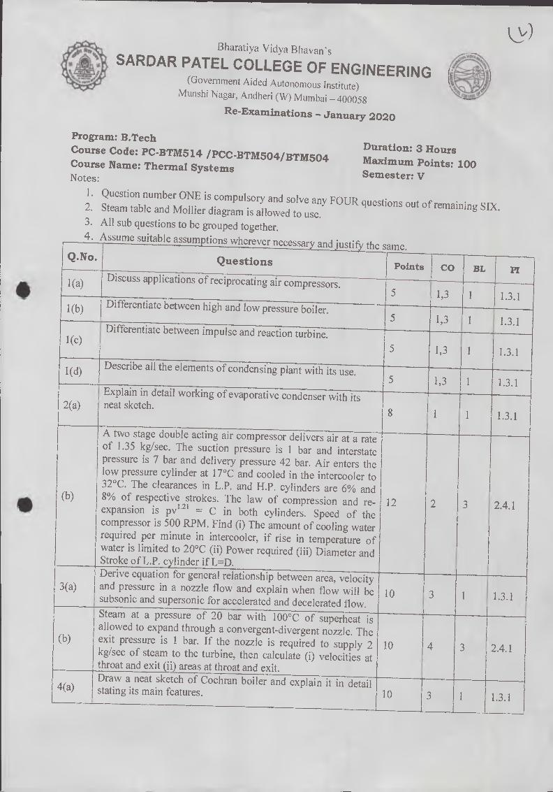
1. Question number ONE is compulsory and solve any FOUR questions out of remaining SIX.
2. Steam table and Mollier diagram is allowed to use. 3. All sub questions to be grouped together. 4. Assume suitable assumptions wherever necessary and justify the same.
Q.No.
1(a)
1(b)
1(c)
(b)
3(a)
(b)
Questions
Discuss applications of reciprocating air compressors.
Differentiate between high and low pressure boiler.
Differentiate between impulse and reaction turbine.
Describe all the elements of condensing plant with its use.
Explain in detail working of evaporative condenser with its neat sketch.
A two stage double acting air compressor delivers air at a rate of 1.35 kg/sec. The suction pressure is 1 bar and interstate pressure is 7 bar and delivery pressure 42 bar. Air enters the low pressure cylinder at 17°C and cooled in the intercooler to 32°C. The clearances in L.P. and H.P. cylinders are 6% and 8% of respective strokes. The law of compression and re-expansion is PV1.21 = C in both cylinders. Speed of the compressor is 500 RPM. Find (i) The amount of cooling water required per minute in intercooler, if rise in temperature of water is limited to 20°C (ii) Power required (iii) Diameter and Stroke of L.P. cylinder if L=D. Derive equation for general relationship between area, velocity and pressure in a nozzle flow and explain when flow will be subsonic and supersonic for accelerated and decelerated flow.
Steam at a pressure of 20 bar with 100°C of superheat is allowed to expand through a convergent-divergent nozzle. The exit pressure is I bar. If the nozzle is required to supply 2 kg/sec of steam to the turbine, then calculate (i) velocities at throat and exit (ii) areas at throat and exit. Draw a neat sketch of Cochran boiler and explain it in detail stating its main features.
4
3
1.3.1
1.3.1
2.4.1
5
10
CO BL Points
5 1.3.1
5 1,3
1,3 1
1.3.1
3
1(d)
1
1,3 1
1.3.1
1.3.1
1.3.1
12
2.4.1
4(a)
10
10
PI
2(a) 8

Bharatiya Vidya Bhavan's
SARDAR PATEL COLLEGE OF ENGINEERING (Government Aided Autonomous Institute)
Munshi Nagar, Andheri (W) Mumbai — 400058
Re-Examinations — January 2020
A steam turbine develops 160 kW with a consumption of 19.4 kg/kWh. The pressure and temperature of the steam entering the nozzle are 12 bar and 220°C. The steam leaves the nozzles at 1.2 bar. If the diameter of the nozzle at throat is 7 mm, find the number of nozzles required. If 8 % of the total enthalpy drop is used up in frictional reheating in the diverging part of the nozzle, determine the diameter at the exit of nozzle and quality of steam leaving the nozzle. Explain the phenomenon of surging and chocking in centrifugal compressors.
In a single stage impulse turbine, the diameter of the blade ring is lm and speed is 3000 RPM. The steam is issued from a nozzle at 300 m/sec and the nozzle angle is 20°. The blades are equiangular. If the friction loss in the blade channel is 19% of the K.E. corresponding to the relative velocity at the inlet to the blades, find power developed in the blading when the axial thrust on the blades is 90 N. Compare rotary and reciprocating compressors.
Prove that condition for maximum blade efficiency in case of 50% reaction turbine is given by relation:
2 cos2a l+cos2a
Explain methods to improve efficiency of open cycle gas 7(a) turbine.
The following data apply to a gas turbine set using a heat exchanger: Isentropic efficiency of compressor = 0.83, Isentropic efficiency of turbine = 0.85, Mechanical transmission efficiency = 0.99, combustion efficiency = 0.98, Heat exchanger effectiveness = 0.80, Pressure ratio = 4.0, Maximum cycle temperature = 1100 K, Ambient condition = 1 bar and 288 K, Lower heating value of fuel = 43,100 kJ/g. Take Cp=1.005 kJ/kg.K, = 1.4 during compression and Cp = 1.147 kJ/kg.K, 7 = 1.3 during combustion and expansion. Calculate specific work output, specific fuel consumption and cycle efficiency. Neglect all losses.
(b)
5(a)
(b)
6(a)
(b)
ilb
(b) 12
10
10 1.3.1
10 2.4.1
10
10
1.3.1
1.3.1
08 3 1.4.1
4
3
2.4.1

Bharatiya Vidya Bhavi,
SARDAR PATEL COLLEGE OF ENGINEERING (Government Aided Autonomous Institute)
Munshi Nagar, Andheri (W) Mumbai — 400058
END SEMESTER - January 2020 Re-Examinations
Program: B. Tech. (Mechanical Engineering) Duration: 03 Hrs Course Code: BTM503
Maximum Points: 100 Course Name: Mechatronics Semester: V Notes: 1. Question Number 1 is compulsory 2. Attempt any four questions from remaining (Q. No. 2 to Q. No. 7) 3. If necessary assume suitable data with justification 4. Draw neat labeled sketch
Q. No. Questions Points CO BL PI
1(A) Draw Bode plot and comment on stability for
200(S + 5) GsHs = () () 10 4 4 3.3.2
S (S + 1)(S + 100)
1(B) Using Routh's Criteria find stability of the control system having characteristics equation
S6 + 4 S5 + 3 S4 — 16 S2 — 64 S — 48 = 0 10 3 3 1.3.1
2(A) Find root locus for
K (S + 5) G (s) H = (s) 10 4 1 2.3.1
S (S + 20)
2 (B) Explain architecture of 8051 microcontroller with neat block and pin diagram 10 1 2 1.3.2
A) 10
Two double acting pneumatic cylinders A, B are selected for an industrial application. The sequence of movement for cylinder is as indicated below—
A+ Delay B+ B- A- Design pure pneumatic circuit considering 4/2 air-air operated
final directional control valves for cylinder A and B.
3 4 3.2.2
3 B) (
Actuators
Explain execution of cloth washing on automatic washing Machine system in the form of (i)Information Systems (ii) Mechanical Systems (iii) Electrical systems (iv) Sensors and 10 1 3 1.3.1
4(A) Draw Polar plot and comment on stability of system for
100 G (s) H (s) = 10 4 5 3.3.1
S (S + 2)(S + 4)
4 (B) Draw programmable logic diagram for the following sequence of operation A+ Delay A- 10 2 5 2.3.3
5(A)
Two double acting hydraulic cylinders A, B are selected for an
industrial application. The sequence of movement for cylinder is as indicated below—
A+B+ B- Delay A- Draw the electrohydraulic circuit using 4/3 double solenoid as
10 3 4 3.3.1

Bharati. a Viciya Bhavan s
'ATEL COLLEGE OF ENGINEERING (Government Aided Autonomous Institute)
Munshi Nagar, Andheri (W) Mumbai — 400058
END SEMESTER - January 2020 Re-Examinations
final directional Control valves. i
5(B)
A second order system
function
G(S) = 500
has unity feedback and open loop transfer
block diagram for closed loop system. equation?
ratio and natural frequency values? peak time, peak overshoot and settling time
output when excited by unit step input. of transient response for unit step input.
rad/s, calculate steady step error.
10 4 3 2.3.2
S (S + 15)
(i) Draw the (ii) What is characteristic (iii) What is damping (iv) Calculate
for the system (v) Rough sketch
If input is ramp of 0.5
6(A)
Find transfer function for the
G3
following control system
C(s) 10 2 3 2.3.1
R(s) 014
+ dm Gi G2
_ 1'4
H2
H1
6(B) Write short note on (a) Servo motor (b) Stepper motor 10 1 1 1.3.1
7 (A)
Two double acting pneumatic cylinders A, B are selected for an
industrial application. The sequence of movement for cylinder is as indicated below-
A- B+ A+ Delay B- Draw the electro-pneumatic circuit using grouping technique. Further use 4/2 and 5/2 double solenoid as final directional Control valves for cylinder A and B respectively.
10 3 3 3.3.1
Open loop transfer function
G (s) = K
7 (B)10
of unity feedback system is
K and Tare constants. Determine factor
be multiplied so that overshoot of unit from 75% to 25%.
4 5 3.3.2 (1+TS)S
where
by which gain `K' should
step response reduced
B harati yaVi d yaBhav an' s
SARDAR PATEL COLLEGE OF ENGINEERING (Government Aided Autonomous Institute)
Munshi Nagar, Andheri (W) Mumbai — 400058
RE-EXAM END SEM ODD SEM DEC 2019
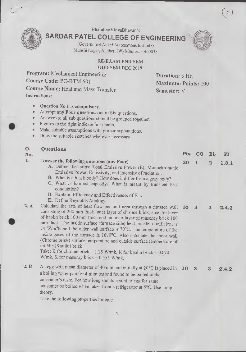
Program: Mechanical Engineering Course Code: PC-BTM 501 Course Name: Heat and Mass Transfer Instructions:
Duration: 3 Hr. Maximum Points: 100 Semester: V
• Question No 1 is compulsory. • Attempt any Four questions out of Six questions. • Answers to all sub questions should be grouped together. • Figures to the right indicate full marks, • Make suitable assumptions with proper explanations. • Draw the suitable sketches wherever necessary
Q. Questions No. 1. Answer the following questions (any Four)
A. Define the terms: Total Emissive Power (E), Monochromatic Emissive Power, Emissivity, and Intensity of radiation.
B. What is a black body? How does it differ from a gray body? C. What is lumped capacity? What is meant by transient heat
conduction? D. Explain: Efficiency and Effectiveness of Fin. E. Define Reynolds Analogy.
2. A Calculate the rate of heat flow per unit area through a furnace wall consisting of 200 mm thick inner layer of chrome brick, a centre layer of kaolin brick 100 mm thick and an outer layer of masonry brick 100 mm thick. The inside surface (furnace side) heat transfer coefficient is 74 W/m2K and the outer wall surface is 70°C. The temperature of the inside gases of the furnace is 1670°C. Also calculate the inner wall (Chrome brick) surface temperature and outside surface temperature of middle (Kaolin) brick. Take: K for chrome brick = 1.25 W/mk, K for kaolin brick = 0.074 Wimk, K for masonry brick = 0.555 W/mk.
2. B An egg with mean diameter of 40 mm and initially at 20°C is placed in a boiling water pan for 4 minutes and found to be boiled to the consumer's taste. For how long should a similar egg for same consumer be boiled when taken from a refrigerator at 5°C. Use lump theory.
Take the following properties for egg:
Pts CO BL PI
20 1 2 1.3.1
10 3 3 2.4.2
10 3 3 2.4.2

10 3 3 2.4.2
10 3 3 2.4.2
10 3 3 2.4.2
10 3 3 2.4.2
10 3 3 2.4.20
05 1 2 1.3.1
05 1 2 1.3.1
10 3 3 2.4.2
K = 10 W/m°C, p = 1200 Kg/m3, C = 2 KJ/Kg°C and h (heat transfer
coefficient) = 100 W/m2 °C.
3. A A carbon steel (K = 54 W/mK) rod with a cross-section of an equilateral triangle (each side 5 mm) is 80 mm long. It is attached to a plane wall which is maintained at a temperature of 400°C. The
surrounding air temperature is 50°C and heat transfer coefficient h is
90 W/m2K. Calculate the heat dissipated by the rod. Assume a rod (fin) insulated at the tip.
3. B Air stream at 24°C is flowing at 0.4 m/s across a 100 W incandescent bull) at 130°C. If the bulb is approximated by 65 rnm_ diameter sphere, calculate:
1. The heat transfer rate, and 2. The percentage of power lost due to convection.
Use equation: Nu = 0.37 (Re)°6° The thermo-properties of air at bulk mean temperature are: K ---- 0.03 W/m2K, v = 2.08 x 10'6 m2/s, Pr = 0.697
4. A A cylindrical body of 300 mm diameter and 1.6 m height is maintained at a constant temperature of 37°C. The surrounding air temperature is 14°C. Find out the amount of heat to be generated by the body per hour. Use equation: Nu = 0.12 (Gr.Pr)°33 The thermo-properties of air at bulk mean temperature are: Cp = 1005 J/kgK, K = 0.02673 W/m2K, v = 16 x 10.6 m2/s, Pr = 0.701
4. B Derive an expression for LMTD for Counter flow heat exchanger with neat sketch.
5. A Two large parallel plates at temperature 1000 K and 600 K have emissivity of 0.5 and 0,8 respectively. A radiation shield having emissivity 0.1 on one side and 0.05 on the other side is placed between the plates. Calculate-the -heat transfer rate by radiation per square meter with and without radiation shield.
5. B 1) State Fick's law of diffusion. Define the various symbols used and give their units. 2) What are the limitations of Pick's law of diffusion? And list and explain various modes of mass transfer.
6. A The flow rates of hot and cold water streams running through a parallel flow heat exchanger are 0.2 kgis and 0.5 kg/s respectively. The inlet temperatures on the hot and cold sides are 75°C and 20°C respectively. The exit temperature of hot water is 45°C. If the individual heat transfer coefficients on both sides are 650 'W/m2K,
2

calculate the area of the heat exchanger. 6. B State and explain Kirchhoff's law of radiation. What is intensity of
radiation? Prove that total emissive power is it times the intensity of radiation.
7. Answer the following questions (Any Four) A. What is Newton's law of viscosity? What is the relation between kinematic viscosity and dynamic viscosity? B. Explain the radiation shield with its applications. C. How are heat exchangers classified? Define effectiveness of heat exchanger. D. State and explain different types of non-dimensional numbers used in free and forced convection. E. State and explain different types of Fouling observed in heat exchangers
10 2 2 2.4.2
20 1 2 1.3.1
3
Bharatiya Vidya Bhavan's
SARDAR PATEL COLLEGE OF ENGINEERING (Government Aided Autonomous institute)
Munshi Nagar, Andheri (W) Mumbai — 400058
Re-Examinations — January 2020
Program: B.Tech Duration: 3 Hours Course Code: PC-BTM514 /PCC-BTM504/BTM504 Maximum Points: 100 Course Name: Thermal Systems Semester: V Notes:
I. Question number ONE is compulsory and solve any FOUR questions out of remaining SIX. 2. Steam table and Mollier diagram is allowed to use. 3. All sub questions to be grouped together. 4. Assume suitable assumptions wherever necessary and justify the
Points CO I BL
1(a) 1 Discuss applications of reciprocating air compressors.
1(b) J Differentiate between high and low pressure boiler.
Differentiate between impulse and reaction turbine.
5
Q.No. I Questions
5
5 11,3
1,3
1(c) 1,3 • 1
PI
1 1.3.1
1 1.3.1
1.3.1
1(d) Describe all the elements of condensing plant with its use. 5 1,3 1 1.3.1
Explain in detail working of evaporative condenser with its 2(a) neat sketch.
8 1 1 1.3.1
(b)
A two stage double acting air compressor delivers air at a rate of 1.35 kg/sec. The suction pressure is I bar and interstate pressure is 7 bar and delivery pressure 42 bar. Air enters the low pressure cylinder at 17°C and cooled in the intercooler to 32°C. The clearances in L.P. and H.P. cylinders are 6% and 8% of respective strokes. The law of compression and re-expansion is pv1•21 = C in both cylinders. Speed of the compressor is 500 RPM. Find (i) The amount of cooling water required per minute in intercooler, if rise in temperature of water is limited to 20°C (ii) Power required (iii) Diameter and Stroke of L.P. cylinder if L=D.
12 2 3 2.4.1
3(a) Derive equation for general relationship between area, velocity and pressure in a nozzle flow and explain when flow will be 10 subsonic and supersonic for accelerated and decelerated flow. 1.3.1
(b)
4(a)
Steam at a pressure of 20 bar with 100°C of superheat is allowed to expand through a convergent-divergent nozzle. The exit pressure is 1 bar. If the nozzle is required to supply 2 10 kg/sec of steam to the turbine, then calculate (i) velocities at throat and exit (ii) areas at throat and exit. Draw a neat sketch of Cochran boiler and explain it in detail r stating its main features. 10
2.4.1
1.3.1

Bharatiya Vidya f3havan's
SARDAR PATEL COLLEGE OF ENGINEERING (Government Aided Autonomous Institute)
Munshi Nagar, Andheri (W) Mumbai — 400058
Re-Examinations — January 2020
(b)
7(a)
A steam turbine develops 160 kW with a consumption of 19.4 kg/kWh. The pressure and temperature of the steam entering the nozzle are 12 bar and 220°C. The steam leaves the nozzles at 1.2 bar. If the diameter of the nozzle at throat is 7 mm, find the number of nozzles required. If 8 % of the total enthalpy drop is used up in frictional reheating in the diverging part of 1 the nozzle, determine the diameter at the exit of nozzle and quality of steam leaving the nozzle. Explain the phenomenon of surging and chocking in centrifugal compressors.
In a single stage impulse turbine, the diameter of the blade ring is 1 m and speed is 3000 RPM. The steam is issued from a nozzle at 300 m/sec and the nozzle angle is 20°. The blades are equiangular. If the friction loss in the blade channel is 19% of the K.E. corresponding to the relative velocity at the inlet to the blades, find power developed in the blading when the axial thrust on the blades is 90 N. Compare rotary and reciprocating compressors.
Prove that condition for maximum blade efficiency in case of 50% reaction turbine is given by relation:
2 cos2a lb =
i+cos2a
Explain methods to improve efficiency of open cycle gas turbine. 08
6(a)
(b)
5(a)
(b)
10
10
1 1.3.1
1.3.1
41 10 2.4.1
10 1.3.1
10 1.3.1
1.4.1
(b)
The following data apply to a gas turbine set using a heat exchanger: Isentropic efficiency of compressor = 0.83, Isentropic efficiency of turbine = 0.85, Mechanical transmission efficiency = 0.99, combustion efficiency = 0.98, Heat exchanger effectiveness = 0.80, Pressure ratio = 4.0, Maximum cycle temperature = 1100 K, Ambient condition = 1 bar and 288 K, Lower heating value of fuel = 43,100 kJ/g. Take Cp-1.005 kJ/kg.K, y = 1.4 during compression and Cp = 1.147 kJ/kg.K, y = 1.3 during combustion and expansion. Calculate specific work output, specific fuel consumption and cycle efficiency. Neglect all losses.
12 4
2.4.1
Bharatiya Vidya Bhavan's
SARDAR PATEL COLLEGE OF ENGINEERING (Government Aided Autonomous Institute)
Munshi Nagar, Andheri (W) Mumbai - 400058
Re-Exam January 2020 Examinations
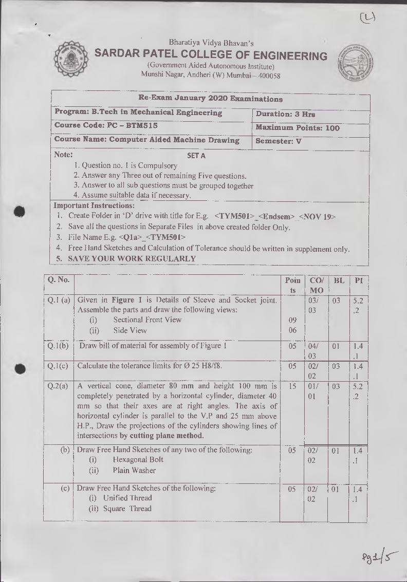
Program: B.Tech in Mechanical Engineering Duration: 3 Hrs Course Code: PC - BTM515 Maximum Points: 100 Course Name: Computer Aided Machine Drawing Semester: V
Note: SETA 1. Question no. 1 is Compulsory 2. Answer any Three out of remaining Five questions. 3. Answer to all sub questions must be grouped together 4. Assume suitable data if necessary.
Important Instructions: 1. Create Folder in 'D' drive with title for E.g. <TYM501>_<Endsem>_<NOV 19> 2. Save all the questions in Separate Files in above created folder Only. 3. File Name E.g. <Q1a>_<TYM501> 4. Free Hand Sketches and Calculation of Tolerance should be written in supplement only. 5. SAVE YOUR WORK REGULARLY
Q. No. Poin ts
CO/ MO
BL PI
Q.1 (a) Given in Figure 1 is Details of Sleeve and Socket joint. 03/ 03 5.2 Assemble the parts and draw the following views: 03 .2
(i) Sectional Front View 09 (ii) Side View 06
Q.1(b) Draw bill of material for assembly of Figure 1 05 04/ 01 1.4 03 .1
Q.1(c) Calculate the tolerance limits for 025 H8/f8. 05 02/ 03 1.4 02 .1
Q.2(a) A vertical cone, diameter 80 mm and height 100 mm is 15 01/ 03 5.2 completely penetrated by a horizontal cylinder, diameter 40 mm so that their axes are at right angles. The axis of horizontal cylinder is parallel to the V.P and 25 mm above
01 2
H.P., Draw the projections of the cylinders showing lines of intersections by cutting plane method.
(b) Draw Free Hand Sketches of any two of the following: 05 02/ 01 1.4 (i) Hexagonal Bolt 02 .1 (ii) Plain Washer
(c) Draw Free Hand Sketches of the following: 05 02/ 01 1.4 (i) Unified Thread 02 .1 (ii) Square Thread
_

5.2 Q.3(a) Given in Figure 3 is Details of Universal Coupling. Assemble 03/ 03 .2
the parts and draw the following views: 04 (i) Sectional Front View 09 (ii) Top View 06
(b) Prepare Bill of Material for the assembly of Figure 3 05 04/ 01 1.4 04 .1
(c) Draw Free Hand Sketches of following: 05 02/ 01 1.4 (i) Round Key 03 .1 (ii) Flat Saddle Key
Q.4(a) Given in Figure 4 (a) is Partial Front View and Partial 03/ 03 5.2 Sectional side view of V- Belt Pulley. Draw the following views:
05 .2
(i) Side View. 07 (ii) Detail view of V-groove and V-Belt. 03
(b) Given in Figure 4 (b) is Sectional Front view and Side View 04/ 03 5.2 of Assembly of Steam Stop Valve. Identify the following parts 06 .2 and draw their views as directed: 05 (i) Valve Cover — (A) Sectional Front View
05 (B) Side View
(ii) Handle — Sectional Front View 05
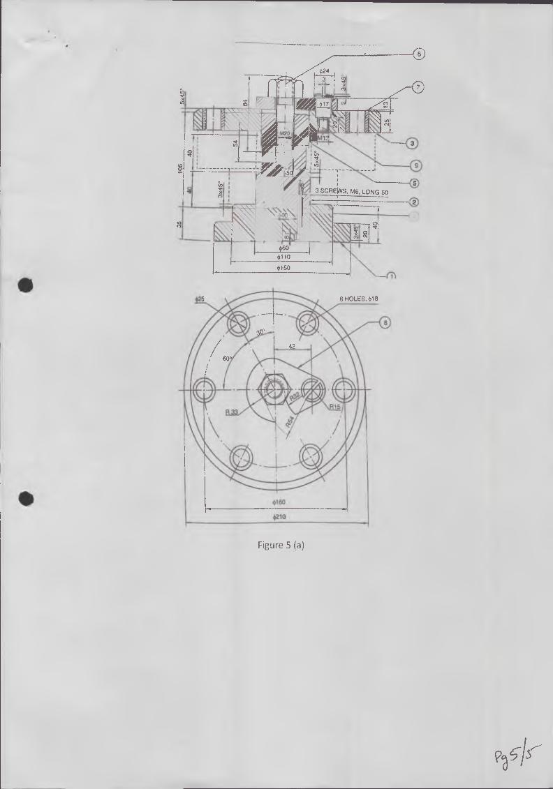
Q.5(a) Given in Figure 5(a) is Assembly of Drill Jig. Identify the 04/ 03 5.2 following parts and draw their views as directed: 07 .2 (i) Jig Plate — (A) Sectional Front View 05
(B) Top View 05 (ii) Stem — Front View 05
(b) 1
Given in Figure 5(b) is Assembly of Expansion Pipe Joint. Identify the following parts and draw their views as directed:
05 04/ 05
03 5.2 .2 (i) Gland — Sectional Front View.
(c) Calculate the tolerance limits between Neck Bush and Body 05 02/ 03 1.4 of expansion joint for 0170. 02 .1

Figure 1
co
8
CENTER BLOCK
1-OFF HOLE $ 6 FOR $30H8 •TAPER PIN
$50
X
30 56
KEY WAY 6H7x 5
Alp% 30H8
FORK 2- OFF
PIN 2-OFF
TAPER 1 IN 100
TAPER PIN 2-OFF
R 38
CO -0-
50
2
COtter Holes 10 Thick with Taper to suit the Cotter
A
240
SLEEVE 1no
Cotter Holes 10 Thick with Taper to suit the Cotter
ROD Left: 1no.
35 I Cotter 2nos.
COLLER
Figure 3

70
20
Keyway 6x3
Details of V-Groove and V-Belt
4 4
Front View Partial Sectional Side View
Figure 4(a)
150 sj
ofl
KEY3x 3 60
VAI WiaPtiM re4
410 A 6.4 ii r
100
M-56 FtNE
72 fl
Figure 4(b)
+24
0
3 SCREWS, M6, LONG 50
+60 +110
+150
N.
a
1
6 HOLES, +18 •
• Figure 5 (a)

50 _ 70
/
/,1
100 100 I 20 22
L
Figure 5(b)

SARDAR PATEL COLLEGE OF ENGINEERING (Government Aided Autonomous Institute)
Munshi Nagar, Andheri (W) Mumbai — 400058
Re exam January 2020
Program: T.Y. B.Tech Mechanical Engineering
Course Code: PC — BTM512
Course Name: Dynamics of Machinery
Instructions: • Attempt any five questions • Assume suitable data wherever necessary and justify the same • Figures to the right indicate full marks • Answers to all questions should be grouped together.
Duration: 03 Hours
Maximum Points: 100
Semester: V
Q.No. Questions Poi nts
CO BL PI
QI (a)
Describe the following: I. Bevis Gibson dynamometer
II. Belt transmission dynamometer 10 CO1 L3 2.1.
Q1 (b)
a) In a prony brake dynamometer, the spring balance reading is 200 N, radius of brake drum is 0.3 m, and distance between the drum axis and the hinge of the blocks is 0.6m. Determine the pressure exerted on the drum by tightening the screw, tangential force acting on the brake drum, and the output power of the prime mover if the record speed is 300 rpm. Take coefficient of friction equal to 0.25.
b) Explain the working principle of Rope and brake dynamometer.
08
02
CO1 L4 2.1.3
Q2
(a) Derive an expression for the gyroscopic couple of a disc.
08 2.4.1 CO1 L6
Q2 (b)
A four wheel vehicle of mass 2500 Kg has a wheel base 2.5 m, track width 1.5 m, and height of centre of gravity 0.6 m above the ground level and lies at 1 m from the front axle. Each wheel has an effective diameter of 0.8 m and a moment of inertia of 0.8 kg-m2. The drive shaft, engine flywheel and transmission are rotating at four times the speed of road wheels, in clockwise direction when viewed from the front, and is equivalent to a mass of 80 kg having a radius of gyration of 100 mm. If the vehicle is taking a right turn of 60 m radius at 60 km/hr, find the load on each wheel.
12
2.1 3 COI L3
Q3 (a)
a) Derive an expression for power and effort of the governor. b) Recite the following terms:
• Equilibrium speed • Mean speed • Height • Pickering
06
04
CO1 Li, L5 2.3.1
Q3 (b)
A porter governor has equal arms of 260 mm length each and pivoted on the axis of rotation. Each ball is of 60 N weight and the weight of the central load is 260 N. The radius of rotation of the ball is 160 mm when the governor begins to rise and 250 mm when the governor is at maximum speed. Find the range of speed, sleeve lift, governor effort, and power of the governor, when the friction at the sleeve is neglected.
10
CO1
j
L4 2.1.3
I

* ,
Q4 (a)
In epicyclic gear train as shown in figure has sun wheel S of 30 teeth and two planet wheels P-P of 40 teeth. The planet wheels mesh with the internal teeth of a fixed annulus A. The driving shaft carries the sun wheel transmits 4 KW at 360 rpm. The driven shaft is connected to an arm, which carries the planet wheels. Determine the speed of the driven shaft and the torque transmitted, if
the overall efficiency is 95%.
12 CO1 L4 2.1.3
Q4 (b)
Q5 (a)
In a reverted epicyclic gear train shown in figure, the arm F carries two wheels A and D and a compound wheel B, C. The wheel A meshes with wheel B and the wheel D meshes with wheel C. TA=80, TD=48 and Tc=72. Find the speed
and direction of wheel D when wheel A is fixed and arm F makes 240 rpm clockwise.
Define the following terms: 1. Motion 2. Degree of freedom 3. Time period 4. Amplitude 5. Oscillatory motion
Determine the natural frequency of the system as shown in figure:
08 CU] L3 1.0
10 CO3 Ll 2,3.1
Q5 (b) 10
Q6 Derive an expression for critical damping, overdamping and underdamping
(a) conditions of a vibratory system. _112
CO3 L6 1.1.2
CO4 L6 ! 2,4.1
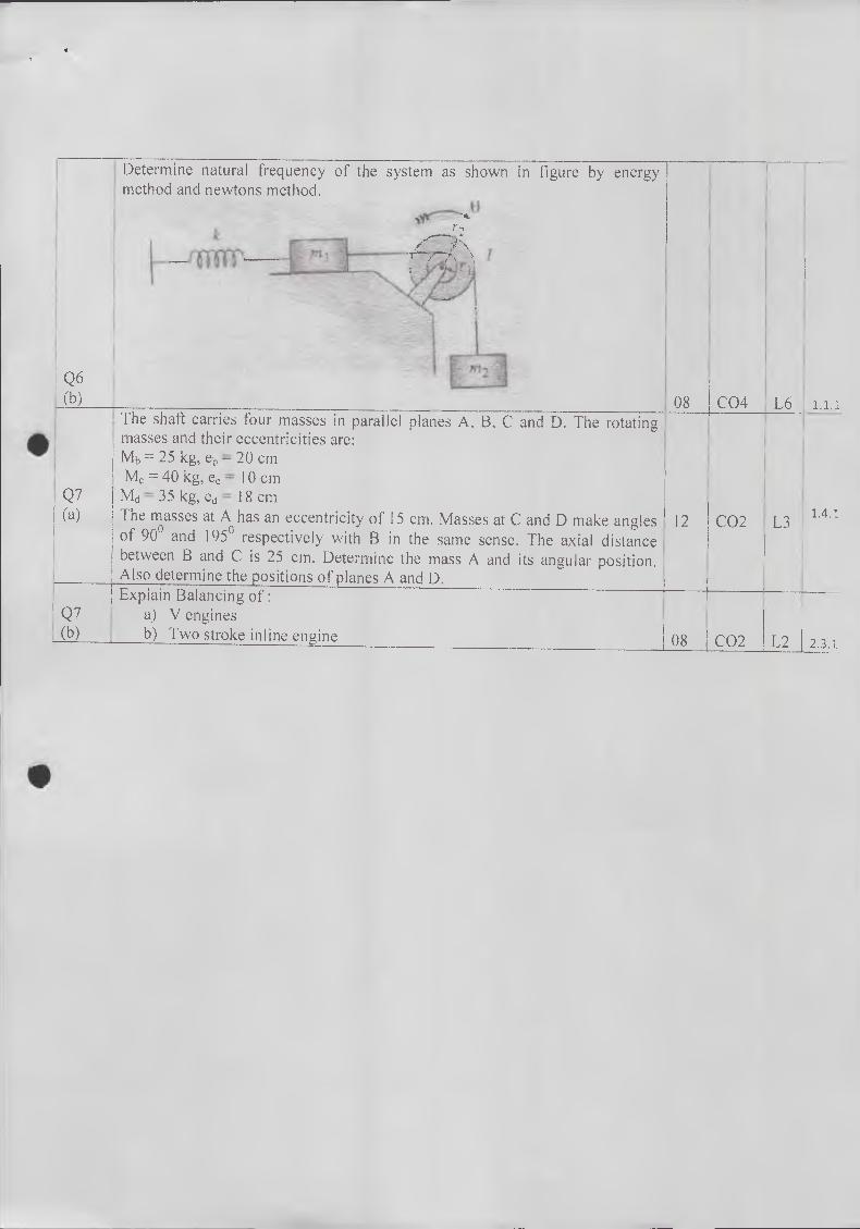
Determine natural frequency of the system as shown in figure by energy , method and newtons method.
masses and their eccentricities Mb -= 25 kg, eb = 20 cm Mc = 40 kg, ec = 10 cm
Q7 Ma = 35 kg, ed = 18 cm
Q6 (b) 08 1 C04 L6 1.1.1 1
The shaft carries four masses in parallel planes A, B, C and D. The rotating 1 I
are: i i
(a) The masses at A has an eccentricity of 15 cm. Masses at C and D make angles of 90° and 195° respectively with B in the same sense. The axial distance between B and C is 25 cm. Determine the mass A and its angular position. Also determine the positions of planes A and D. Explain Balancing of:
Q7 a) V engines (b) b) Two stroke inline engine
•
12 CO2 L3 1.4.1
08 CO2 L2 2.3.1