367 Challenger Liquid Parts List - 367 Challenger 4-Way ...natvac.com/legacy/pdf/367_OM.pdf · Oil...
32
www.natvac.com | 800.253.5500 www.natvac.com | 800.253.5500 1 367 Challenger Owner’s Record Date of Purchase: _____________________________ Purchased from: ______________________________ Serial Number: _______________________________ Model #:_____________________________________ National Vacuum Equipment, Inc. 64 Key Part # Description 1 AP-312-3/W 4-Way Valve Handle Washer 2 AP-312-3/RH Valve Handle 3 AP-318-T Tower, 4-Way Valve/Filter 4 AP-312-3/S Seal, 4-Way Valve Viton 5 R01-252V O-Ring, 2-252 Viton 75 Duro 6 AP-318-SPR Spring, 4-Way Valve Spring 7 AP-318-P Valve Plug, 4-Way Valve w/Filter 8 AP-318-3VH Housing, 3” 4-Way w/Filter 9 A-20025D009G2 Thermometer 10 AP-312-3FO O-Ring, 2-154 Silicone 70 Duro 11 AP-312-3/F 4-Way Valve Flange, 3” NPT 12 AP-312-3/FW Weld Flange, 3” 4-Way Valve 13 AP-318-VFHG Gasket, 4-Way Valve/Filter Hsg 14 AP-318-FE Filter Element, Inlet Valve 15 AP-318-3FH Filter Housing, 3” 4-Way 16 AP-318-FCG Gasket, 4-Way Filter Cover 17 AP-318-FC Filter Cover, 4-Way 18 AP-318-TS Knob, 3/8-16 UNC 19 A-318-3 4-Way Valve & Filter Assembly Liquid Parts List - 367 Challenger 4-Way Filter Valve
-
Upload
nguyenkhue -
Category
Documents
-
view
229 -
download
2
Transcript of 367 Challenger Liquid Parts List - 367 Challenger 4-Way ...natvac.com/legacy/pdf/367_OM.pdf · Oil...
www.natvac.com | 800.253.5500www.natvac.com | 800.253.5500 1
367 Challenger
Owner’s Record
Date of Purchase: _____________________________
Purchased from: ______________________________
Serial Number: _______________________________
Model #:_____________________________________
National Vacuum Equipment, Inc.
64
Key Part # Description
1 AP-312-3/W 4-Way Valve Handle Washer2 AP-312-3/RH Valve Handle3 AP-318-T Tower, 4-Way Valve/Filter4 AP-312-3/S Seal, 4-Way Valve Viton5 R01-252V O-Ring, 2-252 Viton 75 Duro6 AP-318-SPR Spring, 4-Way Valve Spring7 AP-318-P Valve Plug, 4-Way Valve w/Filter8 AP-318-3VH Housing, 3” 4-Way w/Filter9 A-20025D009G2 Thermometer10 AP-312-3FO O-Ring, 2-154 Silicone 70 Duro11 AP-312-3/F 4-Way Valve Flange, 3” NPT12 AP-312-3/FW Weld Flange, 3” 4-Way Valve13 AP-318-VFHG Gasket, 4-Way Valve/Filter Hsg14 AP-318-FE Filter Element, Inlet Valve15 AP-318-3FH Filter Housing, 3” 4-Way 16 AP-318-FCG Gasket, 4-Way Filter Cover17 AP-318-FC Filter Cover, 4-Way 18 AP-318-TS Knob, 3/8-16 UNC19 A-318-3 4-Way Valve & Filter Assembly
Liquid Parts List - 367 Challenger
4-Way Filter Valve

www.natvac.com | 800.253.5500www.natvac.com | 800.253.5500 2
© 2002, 2006 National Vacuum Equipment, Inc. 04/02
No part of this manual may be reproduced without the written permis-sion of National Vacuum Equipment, Inc.
63
Liquid Parts Drawing - 367 Challenger4-Way Filter Valve

www.natvac.com | 800.253.5500www.natvac.com | 800.253.5500 3
IMPO
RTA
NT
INFO
RM
ATIO
N F
OR
SE
TU
P O
F PU
MPS
WIT
H IN
TE
GR
AL
FIN
AL
FILT
ER
CH
ALL
ENG
ER S
ERIE
S PU
MPS
VIE
W O
F N
ON
-DR
IVE
END
Cou
nter
Clo
ckw
ise
Rot
atio
nC
lock
wis
eR
otat
ion
Shad
ed a
rea
mus
t be
kept
cle
ar fo
r ser
vici
ng th
e fil
ter!
62

www.natvac.com | 800.253.5500www.natvac.com | 800.253.5500 4
Contents
IntroductionAbout National Vacuum Equipment, Inc. 6
Limited WarrantyWarranty 8Warranty Procedures 10
367 ChallengerApplication 12Pump Specifications 12System requirements 13Drive system 14Direction of rotation 14Factory Settings 14Adjusting Factory Settings 15
Operating InstructionsNormal Operation 17Recommended Lubricant 18Maintenance 19Cold Weather Operation 20
TroubleshootingPump overheats 21Pump uses too much oil 21Pump doesn’t turn 21No vacuum 22System Troubleshooting 22Making a vacuum tester 23
Table of Contents continues on next page.
61
367
Chal
leng
er - L
iqui
d Co
oled
Par
ts D
iagr
am

www.natvac.com | 800.253.5500www.natvac.com | 800.253.5500 5
Pump RebuildingFan Vane Replacement 24Liquid Vane Replacement 30Fan Complete Rebuild 37Liquid Complete Rebuild 46
Parts ListFan Parts List 53Fan Parts Diagram 55Fan Automatic Oil Pump Parts List and Diagram 57Liquid Parts List 59Liquid Parts Diagram 61Liquid Automatic Oil Pump Parts List and Diagram 63
60
Key Part # Description 46 AP-312-3/T ................Valve Top 47 AP-312-360/RH .........Handle 48 AP-312-3/W ...............Washer 49 B1-0608 .....................3/8-16 x 1 Lg. Hex Head 50 AP-312-3/S ................Seal 51 AP-312-3/SP ..............Spring 52 AP-312-3/P-360 .........Valve Plug 53 360-39 ........................Gasket (Garlock) 56 350-9-HD ...................Seal Sleeve 57 K375375-200 .............Key 3/8 x 3/8 x 2 Lg. 59 AP-311-3....................Spring 61 W-180204 ..................Thermometer 62 460-3 ..........................Drain Valve 63 P2-04-B ......................Brass Plug 64 367-W-LP95D ...........CW Oil Line 367-W-LP95S ............CCW Oil Line 65 367-W-LP97D ...........CW Oil Line 367-W-LP97S ............CCW Oil Line 67 367-W-LP96D ...........CW Oil Line 367-W-LP96S ............CCW Oil Line 68 P8-0416 ......................Dowel Pin

www.natvac.com | 800.253.5500www.natvac.com | 800.253.5500 6
Introduction
General Information
About National Vacuum Equipment, Inc.
Congratulations! You now own a quality vacuum/pressure pump proudly manufactured in the U.S.A. by National Vacuum Equipment, Inc. You have not only acquired a superior piece of equipment from a qualified dealer, you have hired a team of vacuum experts. We stand ready to work with your dealer to answer your questions and provide you with the information necessary to keep your equipment in peak working condition.
Thank you for using National Vacuum Equipment.
OUR MISSION:We are dedicated to the manufacture and wholesale distribution of quality vacuum system products at a reasonable price, on a timely basis. We are a “one-stop shop” for manufacturers and distributors of vacuum equipment.
59
Liquid Parts List - 367 ChallengerSee Parts Diagram Foldout on page 60
Key Part # Description
367-0 Rebuild Kit 367-0B .......................Rebuild Kit w/o Bearings 5 B1-0507 .....................5/16-18 x 7/8 Lg. Hex Head 6 B8-0501 .....................Flat Washer 7 360-54 ........................Bearing Cover 8 400-53V .....................Seal - Viton (40–52–7) 9 360-18V-HD ..............Seal - Viton (60–72–8) 10 367-67G .....................Cover Plate Gasket 11 367-67 ........................Cover Plate 12 350-13F ......................Gasket 13 405-48/R ....................Bearing (NJ308 L1308B) 14 360-LP51 ...................Oil Fitting (4mm Tube x 1/8” NPT 90º Elbow) 15 360-LP56 ...................Oil Fitting (4mm Tube x 1/8” BSPT 90º Elbow) 19 367-3D .......................End Plate (Right Hand Turning) 367-3S ........................End Plate (Left Hand Turning) 20 350-7 ..........................Vane (7 per set) 21 360-5-HD ...................Rotor 22 LF8 ............................Pump Drive Tab 23 360-4 ..........................End Plate Gasket 24 367-1W ......................Pump Housing 25 360-54/OP ..................Oil Tank Mount 27 R31 ............................Gasket 28 LW32AD ...................Oil Pump (Clockwise) LW32AS ....................Oil Pump (Counterclockwise) 30 367-3D .......................End Plate (Right Hand Turning) 367-3S ........................End Plate (Left Hand Turning) 40 A-311-360 ..................Check Valve 41 AP-311-3/R ................Check Valve Retainer 42 AP-312-3/F ................Valve Flange 43 AP-312-3FO ..............O-Ring 44 AP-312-360/H ...........Valve Housing 45 AP-312-3/TG .............Gasket

www.natvac.com | 800.253.5500www.natvac.com | 800.253.5500 7
OUR HISTORY:National Vacuum Equipment, Inc. was founded in 1980 by Bruce Luoma. The Company started as a retailer of vacuum pumps. Soon after it started, the Company secured the rights to exclusive distribution of the Battioni vacuum pumps in North America. This helped the Company to evolve into its current status as a wholesale supplier.
To reach the goal of becoming a full service supplier of vacuum system components, the Company began fabricating its own line of componentry, developed its own line of vacuum pumps, high vacuum blowers and piston gate valves while also purchasing for resale various valves and accessories.
Today, NVE has full service machine and fabrication shops complete with CNC-controlled production equipment designed for close tolerance work. The company has a highly trained staff all of whom are dedicated to quality.
58
Key Part # Description 1 AP-312-3/W 4-Way Valve Handle Washer2 AP-312-3/RH Valve Handle3 AP-318-T Tower, 4-Way Valve/Filter4 AP-312-3/S Seal, 4-Way Valve Viton5 R01-252V O-Ring, 2-252 Viton 75 Duro6 AP-318-SPR Spring, 4-Way Valve Spring7 AP-318-P Valve Plug, 4-Way Valve w/Filter8 AP-318-3VH Housing, 3” 4-Way w/Filter9 A-20025D009G2 Thermometer10 AP-312-3FO O-Ring, 2-154 Silicone 70 Duro11 AP-312-3/F 4-Way Valve Flange, 3” NPT12 AP-312-3/FW Weld Flange, 3” 4-Way Valve13 AP-318-VFHG Gasket, 4-Way Valve/Filter Hsg14 AP-318-FE Filter Element, Inlet Valve15 AP-318-3FH Filter Housing, 3” 4-Way 16 AP-318-FCG Gasket, 4-Way Filter Cover17 AP-318-FC Filter Cover, 4-Way 18 AP-318-TS Knob, 3/8-16 UNC19 A-318-3 4-Way Valve & Filter Assembly
Fan Parts List - 367 Challenger
4-Way Filter Valve

www.natvac.com | 800.253.5500www.natvac.com | 800.253.5500 8
Limited Warranty367 Challenger
National Vacuum Equipment, Inc.
Guarantees that the product it provides is free of manufacturer’s defects, including materials and workmanship. Properly installed and maintained product is warranted for a period of one (1) year subject to the following conditions:
1. A properly completed warranty registration card must be received by us within 30 days of sale to end user for pump sales to be considered warrantable. All pumps received for warranty consideration must retain the original NVE serial number tag.
2. The one (1) year period shall begin the day the product is shipped from our warehouse, unless we are provided with an authentic copy of the original resale invoice, in which case the one (1) year period shall begin at such invoice date.
3. The covered product must be used in an application for which it was intended. We do not recommend our product for particular uses
57
Fan Parts Drawing - 367 Challenger4-Way Filter Valve

www.natvac.com | 800.253.5500www.natvac.com | 800.253.5500 9
4. Vane breakage, or damage caused by vane breakage, is not warrantable.
5. Damage caused by improper use or lack of proper maintenance is not warrantable.
6. Manufacturer’s liability under this or any other warranty, whether express or implied, is limited to repair of or, at the manufacturers option, replacement of parts which are shown to have been defective when shipped.
7. Manufacturer’s liability shall not be enforceable for any product until National Vacuum Equipment, Inc. has been paid in full for such product.
8. Except to the extent expressly stated herein, manufacturer’s liability for incidental and consequential damage is hereby excluded to the full extent permitted by law.
9. Manufacturer’s liability as stated herein cannot be altered except in writing signed by an officer of National Vacuum Equipment, Inc.
10. Certain products provided by National Vacuum Equipment, Inc. are covered by their respective manufacturer’s warranties (e.g., engines used in the NVE engine drive packages). These products are not covered by the National Vacuum Equipment, Inc. Manufacturer’s Warranty.
11. Final assemblers responsibility. NVE goes to great lengths to insure the quality and proper functionality of the products it supplies. Many products we supply are purchased for resale or are impossible or impractical to test prior to the installation of the item in a vacuum system. It is therefore the responsibility of the final assembler to thoroughly test the vacuum system and components supplied to the assembler by
56
NOTES

www.natvac.com | 800.253.5500www.natvac.com | 800.253.5500 10
NVE prior to delivery of the final product to the end user.
Any items found to be defective after delivery to the end user that should have been discovered prior to delivery will qualify for a replacement of the defec-tive part only with absolutely no compensation for outside labor or travel expenses. Any subsequent damage to other components caused by the defective part will be the sole responsibility of the assembler.
Should a potential warranty situation arise, the following procedures must be followed:
• Contact your dealer or NVE immediately upon the occurrence of the event and within the warranty period.
• Customer must receive a return goods authorization (RGA) before returning product.
• All serial-numbered products must retain the NVE serial number tag to be qualified for warranty.
• Product must be returned to NVE intact for inspection before warranty will be honored.
• Product must be returned to NVE freight prepaid in the most economical way.
• Credit will be issued for material found to be defective upon our inspection, based upon prices at the time of purchase.
55
367
Chal
leng
er - F
an C
oole
d Pa
rts
Dia
gram

www.natvac.com | 800.253.5500www.natvac.com | 800.253.5500 11
The 367 Challenger rotary vane vacuum pump is available with fan or liquid cooling. Though the Integral Final Filter is strongly recommend-ed, the pump is available with or without filter. Both versions of the pump (fan and liquid cooled) use the same replacement parts & instal-lation footprint. When tying the liquid cooled version into the truck ra-diator system the installer should connect to the coolest water available. A circulating pump may be required to obtain maximum cooling.
54
Key Part # Description 30 367-3D .......................End Plate (Right Hand Turning) 367-3S ........................End Plate (Left Hand Turning) 31 360-LP98 ...................Oil Line Pickup Tube 32 350-LP1 .....................Oil Tank 33 P1-1200 ......................Drain Plug 34 B2-0507 .....................5/16-18 x 7/8” Soc Head 35 P2-1200-V .................Drain Plug, Vented 36 360-LP91 ...................Oil Line 37 B2-0405 .....................1/4-20 x 5/8” Soc Head 38 360-LP50 ...................Oil Fitting (4mm Tube x 1/8” NPT) 39 BT21 ..........................Shroud Support (9/16” x 2 1/8”) 40 A-311-360 ..................Check Valve 41 AP-311-3/R ................Check Valve Retainer 42 AP-312-3/F ................Valve Flange 43 AP-312-3FO ..............O-Ring 44 AP-312-360/H ...........Valve Housing 45 AP-312-3/TG .............Gasket 46 AP-312-3/T ................Valve Top 47 AP-312-360/RH .........Handle 48 AP-312-3/W ...............Washer 49 B1-0608 .....................3/8-16 x 1 Lg. Hex Head 50 AP-312-3/S ................Seal 51 AP-312-3/SP ..............Spring 52 AP-312-3/P-360 .........Valve Plug 53 360-39 ........................Gasket (Garlock) 54 B6-0204 .....................#8 x 1/2” Tex Screw 55 B1-0514 .....................5/16-18 x 1 3/4 Lg. Hex Head 56 350-9-HD ...................Seal Sleeve 57 K375375-200 .............Key 3/8 x 3/8 x 2 Lg. 58 K375375-100 .............Key 3/8 x 3/8 x 1 Lg. 59 AP-311-3....................Spring 60 P2-1200-SE ................Sight Eye 61 A-20025D009G2 .......Thermometer 62 460-3 ..........................Drain 63 P2-04-B ......................Brass Plug 64 367-LP95 ...................Oil Line 65 367-LP97A ................Oil Line 66 360-LP97 ...................Oil Line 67 360-LP96 ...................Oil Line 68 P9-0824 ......................Dowel Pin
www.natvac.com | 800.253.5500www.natvac.com | 800.253.5500 12
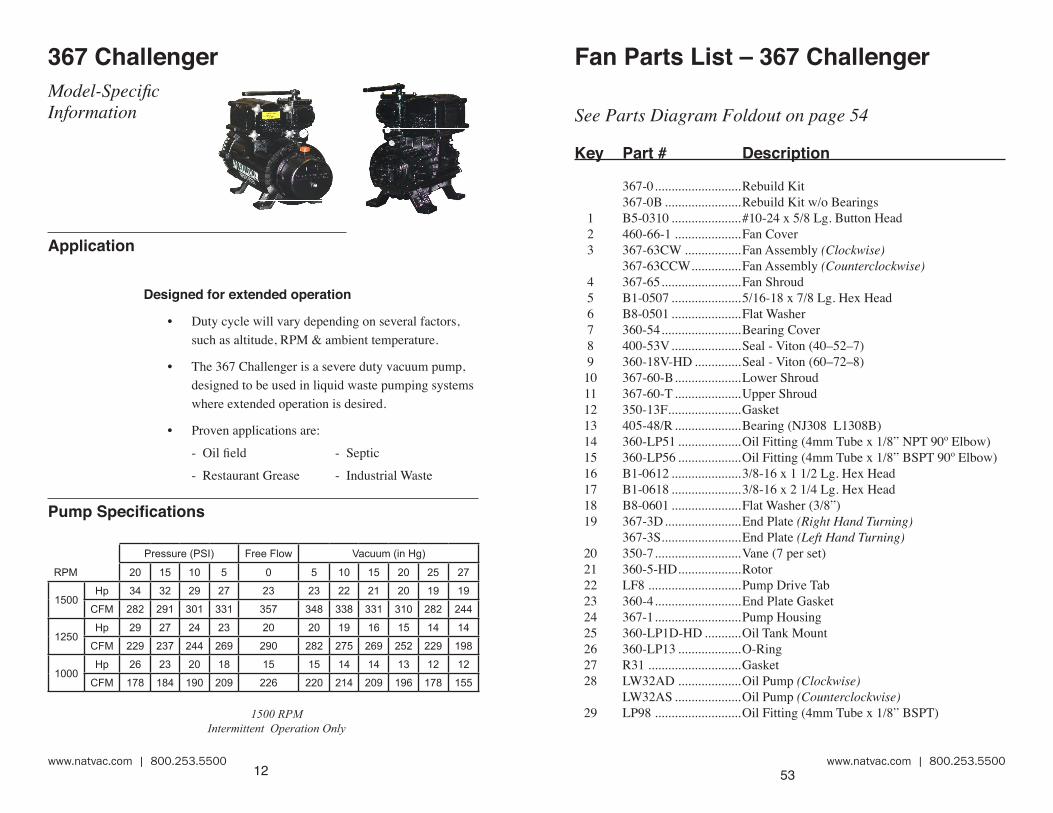
1500 RPM Intermittent Operation Only
367 ChallengerModel-Specific Information
Application
Designed for extended operation
• Duty cycle will vary depending on several factors, such as altitude, RPM & ambient temperature.
• The 367 Challenger is a severe duty vacuum pump, designed to be used in liquid waste pumping systems where extended operation is desired.
• Proven applications are:
- Oil field - Septic
- Restaurant Grease - Industrial Waste
Pump Specifications
53
Fan Parts List – 367 Challenger
See Parts Diagram Foldout on page 54
Key Part # Description
367-0 ..........................Rebuild Kit 367-0B .......................Rebuild Kit w/o Bearings 1 B5-0310 .....................#10-24 x 5/8 Lg. Button Head 2 460-66-1 ....................Fan Cover 3 367-63CW .................Fan Assembly (Clockwise) 367-63CCW ...............Fan Assembly (Counterclockwise) 4 367-65 ........................Fan Shroud 5 B1-0507 .....................5/16-18 x 7/8 Lg. Hex Head 6 B8-0501 .....................Flat Washer 7 360-54 ........................Bearing Cover 8 400-53V .....................Seal - Viton (40–52–7) 9 360-18V-HD ..............Seal - Viton (60–72–8) 10 367-60-B ....................Lower Shroud 11 367-60-T ....................Upper Shroud 12 350-13F ......................Gasket 13 405-48/R ....................Bearing (NJ308 L1308B) 14 360-LP51 ...................Oil Fitting (4mm Tube x 1/8” NPT 90º Elbow) 15 360-LP56 ...................Oil Fitting (4mm Tube x 1/8” BSPT 90º Elbow) 16 B1-0612 .....................3/8-16 x 1 1/2 Lg. Hex Head 17 B1-0618 .....................3/8-16 x 2 1/4 Lg. Hex Head 18 B8-0601 .....................Flat Washer (3/8”) 19 367-3D .......................End Plate (Right Hand Turning) 367-3S ........................End Plate (Left Hand Turning) 20 350-7 ..........................Vane (7 per set) 21 360-5-HD ...................Rotor 22 LF8 ............................Pump Drive Tab 23 360-4 ..........................End Plate Gasket 24 367-1 ..........................Pump Housing 25 360-LP1D-HD ...........Oil Tank Mount 26 360-LP13 ...................O-Ring 27 R31 ............................Gasket 28 LW32AD ...................Oil Pump (Clockwise) LW32AS ....................Oil Pump (Counterclockwise) 29 LP98 ..........................Oil Fitting (4mm Tube x 1/8” BSPT)
RPM
Pressure (PSI) Free Flow Vacuum (in Hg)
20 15 10 5 0 5 10 15 20 25 27
1500Hp 34 32 29 27 23 23 22 21 20 19 19
CFM 282 291 301 331 357 348 338 331 310 282 244
1250Hp 29 27 24 23 20 20 19 16 15 14 14
CFM 229 237 244 269 290 282 275 269 252 229 198
1000Hp 26 23 20 18 15 15 14 14 13 12 12
CFM 178 184 190 209 226 220 214 209 196 178 155
www.natvac.com | 800.253.5500www.natvac.com | 800.253.5500 13
System requirements
High quality components
• The 367 Challenger is a high performance vacuum pump and requires compatible, high quality components as manufactured by NVE.
Shutoffs
• We recommend an 8” cage and a 6” S.S. ball which is standard in all our primary and secondary shutoffs.
Hose
• Use 3” or larger hose to plumb your system. We recommend you use a hose that can withstand high temperatures such as hot tar-asphalt hose.
Pressure relief and vacuum relief valves
• A properly adjusted pressure relief valve and vacuum relief valve should also be incorporated in the system between the secondary and the pump.
• The relief valves should be set to where the pump operates at a maximum temperature of 375° F.
52
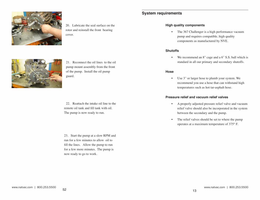
20. Lubricate the seal surface on the rotor and reinstall the front bearing cover.
21. Reconnect the oil lines to the oil pump mount assembly from the front of the pump. Install the oil pump guard.
22. Reattach the intake oil line to the remote oil tank and fill tank with oil. The pump is now ready to run.
23. Start the pump at a slow RPM and run for a few minutes to allow oil to fill the lines. Allow the pump to run for a few more minutes. The pump is now ready to go to work.

www.natvac.com | 800.253.5500www.natvac.com | 800.253.5500 14
Drive system
• The pump should be mounted on a level, horizontal surface, secured with grade 5 or better fasteners.
• The drive system should be sized to supply the required horsepower to the pump plus a reserve to insure long life.
• The P.T.O. must be slowly engaged or it will damage
the pump and drive components.
• Make certain that all shafts, pulleys or turning parts are properly guarded.
• Check the ratio of the drive system prior to installation to verify that the pump will be turning at the proper speed.
Direction of rotation
• The direction of rotation and RPM are marked on the front of the pump.
• The direction of rotation required by your drive system should be determined prior to ordering the pump. Please pay special attention to the orientation of the final filter, which varies with rotation.
Factory Settings
• The automatic lubrication pumps are set at the factory during pump testing and should require no further adjustment during pump installation. The pump should consume 12oz - 15oz of oil per hour. Please contact us if oil usage is outside these parameters.
• It is the responsibility of the installer to ensure proper vacuum and pressure settings and RPM.
51
19. Replace the pump drive key, lubricate the seal surface on the rotor and reinstall the rear bearing cover.
Reinstall the oil pump drive key
Be sure to line up the oil pump drive key and the oil pump shaft prior to tightening the assembly to the pump.

www.natvac.com | 800.253.5500www.natvac.com | 800.253.5500 15
Adjusting Factory Oil SettingsThe automatic oil pump is a metered piston-type pump.Before adjusting the oilers, please follow these basic trouble shoot-ing steps.
1. Make sure the pump (tank) is not under vacuum between jobs.
2. Fill the oil tank to the top at night. Check the oil level before service the next day to ensure no internal leak-ing.
3. Monitor the period of use and measure the oil required to replenish the tank (this should be 12oz -15oz per hour). Compare this with the oil collected from the oil catch muffler.
If after following these steps it is determined that an oil adjustment is needed, then please follow the basic steps below.
1. Drain and remove oil tank.
2. Oil flow is changed by adjusting the length of the stroke of the piston.
3. To adjust the oil rate, remove cap #P16. Under this cap you will find a jam nut #P15 and adjusting screw #P11.
4. Loosen jam nut and turn adjusting screw clockwise to reduce oil flow or counterclockwise to increase oil flow.
5. When making adjustments do so one turn of the screw at a time and test before making further adjustments.
50
17. Seat the bearings in both endplates with a bearing driver or punch.
18. At this point you should be able to turn the pump by hand.
16. Turn the pump around and use the same procedure to mount the front endplate.
15. Remove the dowel pins after tightening the endplate bolts.

www.natvac.com | 800.253.5500www.natvac.com | 800.253.5500 16
Testing flow rate after adjustment
1. Disconnect oil line to observe oil drip rate ensuring adequate lubrication.
2. Adjustments should be done gradually so as not to starve the vacuum pump of oil.
49
12. Locate two pieces of threaded rod 3/8–16 thd. to use as guides and screw them into the two top holes in the housing. Find the two 1/4” dowel pins and insert them into the dowel holes on each side of the housing.
Locate the gaskets and slide it on the threaded rods and dowel pins.
Do not use any gasket sealer.
13. Lubricate seal sleeve and slide the proper endplate on the end of the rotor.
11. Insert the new lubed up vanes, they should slide easily into the rotor slots.
14. When the endplate is close enough to the housing bolt it into place. Tighten endplate bolts to 35–40 ft. lb of torque.

www.natvac.com | 800.253.5500www.natvac.com | 800.253.5500 17
Operating Instructions
367 Challenger
Normal Operation
Oil reservoir• Check oil reservoir daily and fill as required.• Drain and clean periodically depending on service.
Temperature
• Check exhaust temperature it must not exceed 375° F at any time.
Recommended RPM
• Do not operate the pump faster than the recommended rpm of 1200. 1500 RPM for intermittent use.
• To low of an RPM can cause the vanes to clatter (inconsistent contact with the housing) uneven casing wear.
Suction valve
• To operate the suction valve, move the handle in the appropriate direction for either vacuum or pressure; center is neutral.
48
9. Place the inner races onto a hot plate and get them hot. Do not leave them on the plate so long that they become discolored.
7. Locate the replacement seals and install them in the endplates with the seals positioned back to back.
8. Lubricate and install the bearings in the endplates.
10. Use a welding glove to take the hot inner race from the hot plate and slide it onto the rotor shaft. So that the bearing race shoulder is tight against the seal sleeve.
Install on both sides of the rotor.

www.natvac.com | 800.253.5500www.natvac.com | 800.253.5500 18
Vacuum levels
• Do not operate your pump for extended periods of time at vacuum levels which cause the pump to exceed 375° F exhaust gas temperature.
Guards
• Make certain all guards are in place prior to running your pump.
Recommended Lubricant
• We recommend that turbine oil be used in our pumps. Turbine oil is much more resistant to breakdown due to heat than normal motor oil, thereby avoiding the problems associated with motor oil such as lacquering and excessive wear.
• Acceptable oils include:
Penzoil Penzabell 68 T.O.
Shell Turbo 68
Mobil D.T.E. Heavy – Medium
Texaco Regal R & O. 68
47
5. Clean the rotor, rotor slots and housing, inspect for wear or damage.
If the housing needs to be bored or honed, remove only as much material as is necessary to give a smooth clean bore.
The maximum overbore we recommend is .060 inch. A new housing has a bore of 7.875 inches.
If you bore or hone the housing, remove the four way valve assembly and internal check valve prior to machining.
4. Once the rotor is removed, cut off the old bearing inner race on both ends of the rotor. Be sure to line up the cutting wheel with one of the vane slots so as not to damage the rotor or seal sleeve.
6. After the housing is clean lube the inside of the housing and place the clean rotor inside with the drive end in the same orientation it originally was.

www.natvac.com | 800.253.5500www.natvac.com | 800.253.5500 19
Maintenance
Washing
• Periodically wash the mud and dirt off your pump as it must be clean to allow heat to radiate from it.
FlushingWe recommend periodic flushing of your pump. To do this:
1. Connect the hose to the flush valve located on the side of the inlet port.
2. Put the end of the hose in a one pint container of diesel fuel. Start your pump and run as slow as possible.
3. With the suction valve in the vacuum position, monitor the diesel flow to your pump.
4. When the diesel fuel is gone switch the suction valve to neutral and run the pump for 2 minutes.
5. Speed the pump up to normal RPM, switch the suction valve to vacuum.
6. Remove the hose and close the valve.
7. Properly dispose of used oil and flushing fluid.
Checking vane wear
• We recommend checking vane wear at least every 12 months.
• A new vane is flush with the outside diameter of the rotor.
46
1. Follow steps 1-6 in the vane replacement instructions.
2. Place a cushion under the rotor to prevent damage when the front endplate is unbolted.
3. Remove the front bearing plate and endplate from the rotor.
Put an identifying mark on the endplate so as to not confuse it with the rear.
Liquid Cooled Pump Complete Rebuild

www.natvac.com | 800.253.5500www.natvac.com | 800.253.5500 20
• Remove the plug from the vane check port, insert a rod to rotor O.D., rotate rotor until the rod falls into one of the vane slots. If the rod falls more than a 1/4“ into any of the 7 vane slots, it’s time to replace the vanes.
• Vanes should be replaced in sets and it is always a good idea to have an extra set of vanes on hand for emergencies.
Cold Weather Operation
Confirm pump is not frozen.
• Prior to engaging the pump, turn by hand to confirm it is not frozen.
If pump is frozen, thaw it.
• If the pump is frozen, thaw it out by heating the bottom of the pump with a torch or move the truck into a heated building.
Avoid freezing problems.
• You can avoid freezing problems by putting a small amount of diesel fuel into the pump at the end of the day.
45
27. Connect the oil line to the oil pump mount assembly from the front of the pump.
28. Reinstall the oil tank and fill the pump with oil.
The pump is now ready to run.
29. Start the pump at a slow r.p.m. and run for a few minutes to allow oil to fill the lines. Allow the pump to run for a few more minutes. The pump is now ready to go to work.
www.natvac.com | 800.253.5500www.natvac.com | 800.253.5500 21
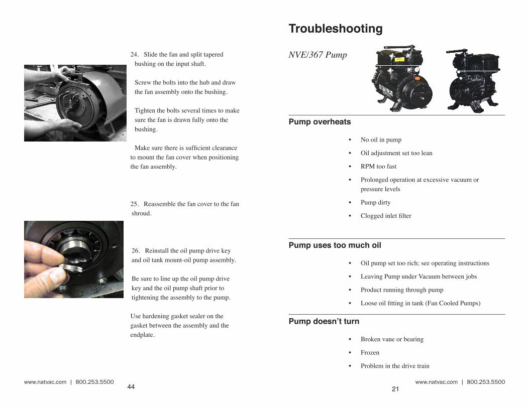
Troubleshooting
NVE/367 Pump
Pump overheats
• No oil in pump
• Oil adjustment set too lean
• RPM too fast
• Prolonged operation at excessive vacuum or pressure levels
• Pump dirty
• Clogged inlet filter
Pump uses too much oil
• Oil pump set too rich; see operating instructions
• Leaving Pump under Vacuum between jobs
• Product running through pump
• Loose oil fitting in tank (Fan Cooled Pumps)
Pump doesn’t turn
• Broken vane or bearing
• Frozen
• Problem in the drive train
44
24. Slide the fan and split tapered bushing on the input shaft.
Screw the bolts into the hub and draw the fan assembly onto the bushing.
Tighten the bolts several times to make sure the fan is drawn fully onto the bushing.
Make sure there is sufficient clearance to mount the fan cover when positioning the fan assembly.
25. Reassemble the fan cover to the fan shroud.
26. Reinstall the oil pump drive key and oil tank mount-oil pump assembly.
Be sure to line up the oil pump drive key and the oil pump shaft prior to tightening the assembly to the pump.
Use hardening gasket sealer on the gasket between the assembly and the endplate.

www.natvac.com | 800.253.5500www.natvac.com | 800.253.5500 22
No vacuum
• Suction valve in neutral
• Worn seals or vanes
• Pump not turning fast enough
• Check valve or suction valve clogged
• Leak in tank or fittings
• Collapsed hose between pump & shutoffs
System Troubleshooting—Locating the source of the trouble
If you notice a decrease in pumping performance, start trou-bleshooting at the pump.
1. Remove the suction and discharge hoses at the pump.
2. Start the pump and run it in vacuum only at its normal RPM.
3. Check the vacuum level at the pump inlet. The 367 Challenger in new condition will develop 27-28.5” hg.
4. If the pump checks out OK, check the vacuum level at the secondary, then the primary shutoff. Keep working your way back until you find the problem.
43
20. Seat the bearings on both endplates with a bearing driver or punch.
21. At this point you should be able to turn the pump by hand.
22. Lubricate the seal surface on the rotor and reinstall the front bearing cover.
Coat the gasket with a hardening gasket sealer.
23. Line up your marks on the aluminum and steel shrouds and attach the shroud to the endplate.
Attach the steel shroud to the aluminum shroud with the Allen screws.

www.natvac.com | 800.253.5500www.natvac.com | 800.253.5500 23
Making a vacuum tester
1. Procure a flange to mount on your four-way valve, a short 3” pipe nipple, a 3”pipe cap and a vacuum gage.
2. Drill and tap a 1/4” N.P.T. thread in the pipe cap.
3. Assemble the flange, nipple, pipe cap and vacuum gage.
4. Remove a flange from the four-way valve on your pump.
5. Start the pump and confirm the location you have chosen to test from is at vacuum.
6. Using the existing O-ring, fasten the testing flange to your pump.
7. Start your pump and read the vacuum level on the gauge.
42
17. Lubricate seal sleeve and install the endplate on the end of the rotor.
Carefully align the endplate to the dowel pins.
18. When the endplate is aligned on the dowel pins and close enough to the housing, install the endplate bolts.
19. Tighten the endplate bolts to 35–40 ft. lb. of torque.
Tighten both endplates in this manner.
www.natvac.com | 800.253.5500www.natvac.com | 800.253.5500 24
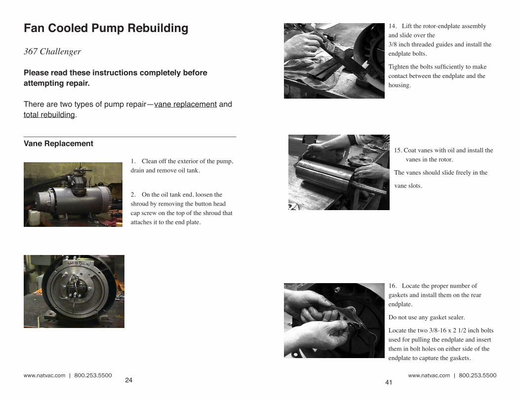
Fan Cooled Pump Rebuilding
367 Challenger
Please read these instructions completely before attempting repair.
There are two types of pump repair—vane replacement and total rebuilding.
Vane Replacement
1. Clean off the exterior of the pump, drain and remove oil tank.
2. On the oil tank end, loosen the shroud by removing the button head cap screw on the top of the shroud that attaches it to the end plate.
41
14. Lift the rotor-endplate assembly and slide over the 3/8 inch threaded guides and install the endplate bolts.
Tighten the bolts sufficiently to make contact between the endplate and the housing.
15. Coat vanes with oil and install the vanes in the rotor.
The vanes should slide freely in the
vane slots.
16. Locate the proper number of gaskets and install them on the rear endplate.
Do not use any gasket sealer.
Locate the two 3/8-16 x 2 1/2 inch bolts used for pulling the endplate and insert them in bolt holes on either side of the endplate to capture the gaskets.

www.natvac.com | 800.253.5500www.natvac.com | 800.253.5500 25
3. Disconnect the oil lines from the oil pump mount that go to the front, and the inlet of the pump.
4. Remove the four bolts that attach the oil pump mount to the end plate and remove oil pump and pump mount assembly.
5. Remove the oil pump drive key from the end of the rotor.
6. Remove the eight bolts that attach the endplate to the pump.
40
11. Locate two pieces of threaded rod 3/8–16 thd. to use as guides and screw them into the two top holes in the housing.
Locate proper number of gaskets and slide on the threaded rods.
Do not use any gasket sealer.
12. Lubricate the housing bore.
13. Lubricate seal sleeve and slide the proper endplate on the input end of the rotor.
Reassemble oil line on the endplate.
Slide rotor-endplate assembly into the pump housing.
Slide the cushion material (used during disassembly) under the rotor on the opposite end to gain leverage during assembly of endplate to housing.

www.natvac.com | 800.253.5500www.natvac.com | 800.253.5500 26
7. Note the number of gaskets on the end plate. You must use the same number of gaskets during reassembly.
8. Inspect vanes, bearings and seals and replace as necessary.
A new vane is flush with the outside diameter of the rotor.
If they are worn more than 1/4” they should be replaced.
We recommend replacing vanes in sets.
If the ends of the vanes are chipped or delaminated they should be replaced.
The seals should be soft and pliable.
The bearing should turn smoothly.
9. Clean the rotor, rotor slots and housing and inspect for wear or damage.
. . . and pull off the endplate.
39
8. Inspect vanes, bearings and seals and replace as necessary. A new vane is flush with the outside diameter of the rotor. If they are worn more than 1/4” they should be replaced. We recommend replacing vanes in sets.
If the ends of the vanes are chipped or delaminated they should be replaced.
The seals should be soft and pliable.
The bearing should turn smoothly.
9. Locate the replacement seals and install them in the endplates with the seals positioned back to back.
Replace the seals in the bearing cover with the seals back to back.
10. Lubricate and install the bearings in the endplates.

www.natvac.com | 800.253.5500www.natvac.com | 800.253.5500 27
10. Coat the housing and vanes with oil and install the vanes in the rotor. The vanes should slide freely in the vane slot.
11. Locate the replacement seals and install them in the endplate with the seals positioned back to back.12. Lubricate and install the bearing in the endplate.13. Locate the proper number of gaskets and install them on the endplate.Do not use any gasket sealer.Locate the two 3/8–16x2 1/2 inch bolts and insert them in bolt holes on either side of the endplate.
38
5. Remove the oil line and bearing cover. Remove the four bolts attaching the endplate to the housing. Slide the rotor out.
6. Remove the front endplate from the rotor with a puller or hydraulic press.
Put an identifying mark on the endplate so as to not confuse it with the rear. Count the number of gaskets.
7. Clean the rotor, rotor slots and housing and inspect for wear or damage.
If the housing needs to be bored or honed, remove only as much material as is necessary to give a smooth clean bore.
The maximum overbore we recommend is .060 inch. A new housing has a bore of 7.875 inches.
If you bore or hone the housing, remove the four way valve assembly and internal check valve prior to machining.

www.natvac.com | 800.253.5500www.natvac.com | 800.253.5500 28
15. Align the endplate onto the dowel pins and bolt into place. Tighten endplate bolts to 35–40 ft. lb of torque.
16. Seat the bearing with a bearing driver or punch.
14. Lubricate seal sleeve and install the endplate on the end of the rotor and carefully slide the endplate on the rotor.
37
1. Follow steps 1-7 in the vane replacement instructions.
2. Place a cushion under the rotor to prevent damage when the front endplate is unbolted.
3. From the drive end, remove the four screws that attach the fan cover to the shroud.
Loosen the bolt in the collet and remove fan and key’s.
4. Remove the four bolts attaching the aluminum shroud to the endplate and remove the shroud.
Fan Cooled Pump Complete Rebuild

www.natvac.com | 800.253.5500www.natvac.com | 800.253.5500 29
17. At this point you should be able to turn the pump by hand.
18. Reinstall the oil pump drive key and oil tank mount-oil pump assembly.
Be sure to line up the oil pump drive key and the oil pump shaft prior to tightening the assembly to the pump.
Use hardening gasket sealer on the gasket between the assembly and the endplate.
19. Connect the oil line to the oil pump mount assembly from the front of the pump.
36
17. Reconnect the oil lines to the bearing plates, oil inlet and to the oil pump mount assembly. Reinstall the oil pump guard.
18. Reattach the intake oil line to the remote oil tank and fill tank with oil. The pump is now ready to run.
19. Start the pump at a slow RPM and run to allow oil to fill the lines. Allow the pump to run for a few more minutes. The pump is now ready to go to work.

www.natvac.com | 800.253.5500www.natvac.com | 800.253.5500 30
20. Reinstall the oil tank and fill the pump with oil. The pump is now ready to run.
21. Start the pump at a slow RPM and allow to run for a few minutes, loosen the oil fitting to check that oil is flowing. Reconnect the fitting and properly torque.
The pump is now ready to go to work.
35
13. Remove the dowel pins after tightening the endplate bolts.
14. At this point you should be able to turn the pump by hand. If you can not reseat the bearings in both endplates with a bearing driver or punch.
15. Reinstall the oil pump drive key and oil mount-oil pump assembly.
16. Be sure to line up the oil pump drive key and the oil pump shaft prior to tightening the assembly to the pump

www.natvac.com | 800.253.5500www.natvac.com | 800.253.5500 31
Liquid Cooled Pump Rebuilding
367 Challenger
Please read these instructions completely before attempting repair.
There are two types of pump repair—vane replacement and total rebuilding.
Vane Replacement
1. Clean off the exterior of the pump.
2. Remove the oil line guard. Disconnect and remove the oil lines that go to the front bearings and pump inlet from the oil pump.
34
9. Locate the two 3/8–16x2 1/2 inch bolts and insert them in bolt holes on either side of the endplate. Locate the long 1/4” dowels and place them into the housing to locate and guide the endplate into place.
10. Locate the gasket and install it on the endplate. Lubricate seal sleeve and install the endplate on the end of the rotor and
11. Carefully slide the endplate on the rotor and over the guide pins.
12. When the endplate is close enough to the housing bolt it into place. Tighten endplate bolts to 35–40 ft. lb of torque.

www.natvac.com | 800.253.5500www.natvac.com | 800.253.5500 32
3. Remove the remaining two four bolts that hold the oil pump mount to the end plate, and remove the pump and pump mount.
4. Remove the oil pump drive key from the end of the rotor.
5. Remove the eight bolts that attach the rear end plate and slide the end plate off the rotor shaft.
6. Remove the old vanes.
33
7. A new vane is flush with the outside diameter of the rotor.
If they are worn more than 1/4” they should be replaced.
We recommend replacing vanes in sets.
If the ends of the vanes are chipped or delaminated they should be replaced.
The seals should be soft and pliable.
The bearing should turn smoothly.
8. Clean the vane slots.
Coat the vanes with oil and install the vanes in the rotor.
The vanes should slide freely in the vane slot.