349-02787H TRAPEZIUMX User's Guide.pdf
304
SHIMADZU AUTOGRAPH SOFTWARE TRAPEZIUM X Instruction Manual User’s Guide Read the instruction manual thoroughly before you use the product. Keep this instruction manual for future reference. 349-02787H Nov. 2013
-
Upload
stijn-van-vlierberghe -
Category
Documents
-
view
733 -
download
212
Transcript of 349-02787H TRAPEZIUMX User's Guide.pdf
SHIMADZU AUTOGRAPH SOFTWARE
TRAPEZIUM X
Instruction Manual User’s Guide
Read the instruction manual thoroughly before you use the product. Keep this instruction manual for future reference.
349-02787H Nov. 2013

This page is intentionally left blank.
Before Using the Autograph System
Introduction Read this instruction manual prior to operating the product.
Thank you for purchasing the TRAPEZIUMX.
This Guide describes the TRAPEZIUMX operating procedures, mainly showing flow of operations of this software.
If you want to execute any operation, find the corresponding item from the table of contents, and refer to the procedure described for the item.
Please read the instruction manual carefully before using the testing machine.
Keep it stored safely in an accessible location for easy reference.
NOTE Be sure to understand the instructions in this manual before operating the system.
Attach this instruction manual before lending or transferring it to another party.
If this instruction manual or product warning labels are lost or destroyed, promptly contact your Shimadzu representative.
This instruction manual lists safety precautions to ensure the system is operated safely. Be sure to read them before using the system.
Notice This manual is copyrighted by the Shimadzu Corporation. It may not be
reproduced either in whole or in part without the prior permission of Shimadzu Corporation.
Information in this manual is subject to change without notice. The utmost care has been taken in preparing this document, however, if
any errors or omissions are detected, it may not be possible to correct them immediately.
Windows is a registered trademark of Microsoft Corporation in the US and other countries.
Copyright © 2007-2013 Shimadzu Corporation. All rights reserved.

Documentation Conventions
In this instruction manual, the following safety-related signal words are used to indicate the degree of hazard or possible damage.
Symbol Meaning
Indicates a potentially hazardous situation which, if not
avoided, could result in serious injury or possibly death.
Indicates a potentially hazardous situation which, if not
avoided, may result in minor to moderate injury or equipment damage.
[ ]
Text shown in the GUI
(menus, buttons, dialog boxes, and window names) Example: Select [File] - [Save as]
Click [OK]
the [TRAPEZIUMX Home] window
" " Text shown temporarily in a window (such as error messages), and text entered by the user
WARNING
CAUTION

Safety Guidelines Autograph systems generate very large forces used to measure the strength characteristics of materials or products.
In some situations it could cause material damage or serious harm to humans (such as injury or death).
Therefore, to ensure the system is used safely, please thoroughly understand and observe the following warnings.
Operating the system carelessly could result in serious injury or death. Keep hands, head and all other body parts away from the testing space when the crosshead is in motion.
WARNING
Due to risk of electric shock, never touch inside the controller unit, located in the testing machine.
WARNING
Moving parts can produce dangerous forces corresponding to the system capacity. All operators should read the instruction manual thoroughly to ensure they operate the system correctly. Control access to the system to ensure only trained operators operate the system.
WARNING
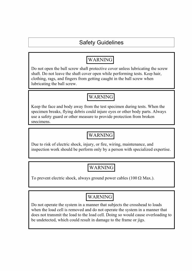
Safety Guidelines
Due to risk of electric shock, injury, or fire, wiring, maintenance, and inspection work should be perform only by a person with specialized expertise.
WARNING
Do not operate the system in a manner that subjects the crosshead to loads when the load cell is removed and do not operate the system in a manner that does not transmit the load to the load cell. Doing so would cause overloading to be undetected, which could result in damage to the frame or jigs.
WARNING
To prevent electric shock, always ground power cables (100 W Max.).
WARNING
Do not open the ball screw shaft protective cover unless lubricating the screw shaft. Do not leave the shaft cover open while performing tests. Keep hair, clothing, rags, and fingers from getting caught in the ball screw when lubricating the ball screw.
WARNING
Keep the face and body away from the test specimen during tests. When the specimen breaks, flying debris could injure eyes or other body parts. Always use a safety guard or other measure to provide protection from broken specimens.
WARNING

Safety Guidelines
For long tests, note that continuous operation is limited to 10 hours for Autograph systems.
CAUTION
This system includes a built-in safety feature that stops jog or return movements if the load level applied to the load cell varies by more than a given amount. This feature is one of the safety circuits, but for fast movements it cannot eliminate the risk of overshooting. Furthermore, for safety and operational convenience reasons, this feature will not stop motion in the unloading direction. Therefore, this feature provides no guarantee that impacts and overloading will be prevented in the testing space. Also, do not use this feature for positioning or other control purposes.
CAUTION
Always use Shimadzu brand testing jigs on Autograph testing machines.
WARNING
Never operate the crosshead without crosshead limit switches in place. Doing so could cause the crosshead to hit the jig and damage the frame, jig, or load cell.
WARNING

Product Warranty Thank you for purchasing this product. Shimadzu provides the following warranty for this product. 1. Warranty Period Please consult your Shimadzu representative for information about
the extent of the warranty. 2. Coverage If the product malfunctions during the warranty period, Shimadzu
ill repair or replace the product (at their discretion) free of charge. 3. Exclusions Even if occurring during the warranty period, this warranty does
not cover the following types of malfunctions.
1) Malfunctions resulting from using or handling the system improperly. 2) Malfunctions resulting from disassembly, repair or modification performed
by any company other than Shimadzu or a Shimadzu-designated company. 3) Malfunctions resulting from causes outside the system. 4) Malfunctions resulting from operating the product in harsh environments,
such as areas subject to high temperatures, high humidity, corrosive gasses or vibration.
5) Malfunctions resulting from fire, earthquakes, or other natural disasters. 6) Malfunctions resulting from moving or transporting the system after
installation. 7) Malfunctions of consumables or the equivalent.
User’s Guide
1
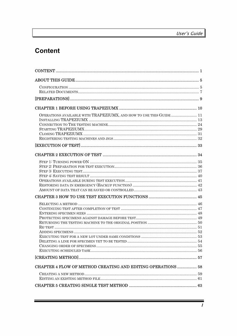
Content
CONTENT ................................................................................................................................... 1
ABOUT THIS GUIDE ................................................................................................................. 5 CONFIGURATION .......................................................................................................................... 5 RELATED DOCUMENTS................................................................................................................. 7
[PREPARATIONS] ...................................................................................................................... 9
CHAPTER 1 BEFORE USING TRAPEZIUMX ....................................................................... 10 OPERATIONS AVAILABLE WITH TRAPEZIUMX, AND HOW TO USE THIS GUIDE ........................ 11 INSTALLING TRAPEZIUMX ..................................................................................................... 13 CONNECTION TO THE TESTING MACHINE................................................................................... 24 STARTING TRAPEZIUMX......................................................................................................... 29 CLOSING TRAPEZIUMX .......................................................................................................... 31 REGISTERING TESTING MACHINES AND JIGS .............................................................................. 32
[EXECUTION OF TEST] .......................................................................................................... 33
CHAPTER 2 EXECUTION OF TEST ...................................................................................... 34 STEP 1: TURNING POWER ON .................................................................................................... 35 STEP 2: PREPARATION FOR TEST EXECUTION............................................................................. 36 STEP 3: EXECUTING TEST........................................................................................................... 37 STEP 4: SAVING TEST RESULT .................................................................................................... 40 OPERATIONS AVAILABLE DURING TEST EXECUTION ................................................................... 41 RESTORING DATA IN EMERGENCY (BACKUP FUNCTION) ............................................................ 42 AMOUNT OF DATA THAT CAN BE SAVED OR CONTROLLED........................................................... 43
CHAPTER 3 HOW TO USE TEST EXECUTION FUNCTIONS ............................................ 45 SELECTING A METHOD ............................................................................................................... 46 CONTINUING TEST AFTER COMPLETION OF TEST ....................................................................... 47 ENTERING SPECIMEN SIZES ....................................................................................................... 48 PROTECTING SPECIMENS AGAINST DAMAGE BEFORE TEST......................................................... 49 RETURNING THE TESTING MACHINE TO THE ORIGINAL POSITION .............................................. 50 RE-TEST ..................................................................................................................................... 51 ADDING SPECIMENS ................................................................................................................... 52 EXECUTING TEST FOR A NEW LOT UNDER SAME CONDITIONS .................................................... 53 DELETING A LINE FOR SPECIMEN YET TO BE TESTED ................................................................. 54 CHANGING ORDER OF SPECIMENS .............................................................................................. 55 EXECUTING SCHEDULED TASK ................................................................................................... 56
[CREATING METHOD]............................................................................................................ 57
CHAPTER 4 FLOW OF METHOD CREATING AND EDITING OPERATIONS .................. 58 CREATING A NEW METHOD ......................................................................................................... 59 EDITING AN EXISTING METHOD FILE.......................................................................................... 61
CHAPTER 5 CREATING SINGLE TEST METHOD .............................................................. 63

Content
2
CREATING A SIMPLE TENSILE TEST METHOD.............................................................................. 64 CREATING A TENSILE TEST METHOD USING AN EXTENSOMETER................................................ 72 CREATING A COMPRESSION TEST METHOD ................................................................................. 78 CREATING A BENDING TEST METHOD ......................................................................................... 83 CREATING A TEAR/PEEL TEST METHOD ...................................................................................... 88 CREATING A CREEP TEST METHOD ............................................................................................. 93
CHAPTER 6 CREATING CYCLE TEST METHOD ...............................................................101 CREATING A SIMPLE CYCLE TEST METHOD............................................................................... 102 CREATING A CYCLE TEST METHOD WITH MANY CYCLES AND RESISTANCE INPUT..................... 107
CHAPTER 7 CREATING CONTROL TEST METHOD .........................................................113 CREATING A SIMPLE UP/DOWN TEST METHOD .......................................................................... 114 CREATING A STEPPED CONTROL TEST METHOD........................................................................ 119
CHAPTER 8 CREATING TEXTURE TEST METHOD..........................................................125 CREATING A PLUNGER COMPRESSION TEST METHOD ............................................................... 126 CREATING A CHEWING TEST METHOD ...................................................................................... 133
[RESULT ANALYSIS AND OUTPUT]....................................................................................143
CHAPTER 9 RE-ANALYZING TEST RESULT......................................................................144 FLOW OF RE-ANALYZING OPERATION ....................................................................................... 145 OPENING A TEST FILE .............................................................................................................. 146 COMBINING SEVERAL TEST FILES............................................................................................. 146 ANALYSIS METHOD SELECTION GUIDE ..................................................................................... 147 BATCH CHANGE OF VARIOUS PARAMETERS (RE-ANALYSIS) – METHOD WIZARD....................... 148 DIRECT CHANGE OF ANALYSIS PARAMETERS ON THE MAIN SCREEN-QUICK SETTING PANEL 149 CHANGING ONLY ANALYSIS PARAMETERS IN THE RESULT WINDOW ......................................... 150 CHANGING PASS/FAIL JUDGMENT CRITERIA IN THE RESULT WINDOW..................................... 151 CHANGING PRINTING ORDER AND PRINT ON/OFF SETTING IN THE RESULT WINDOW ............. 153 SPECIFYING A DATA PROCESSING POINT IN A CHART – POINT PICKING.................................... 155 CHANGING AN ELASTIC LINE SLOPE IN A CHART ...................................................................... 157 CHANGING THE PEEL TEST DATA PROCESSING RANGE IN A CHART .......................................... 159 CHANGING PEEL TEST PEAK/VALLEY CALCULATION EXCLUDING FORCE IN A CHART ............... 161 RESETTING A MANUALLY CHANGED RESULT TO ORIGINAL VALUE THROUGH RE-ANALYSIS ..... 163
CHAPTER 10 PRINTING AND OUTPUT OF TEST RESULT .............................................165 RESULT EXPORT SELECTION GUIDE ......................................................................................... 166 PRINTING A REPORT ................................................................................................................. 167 CREATING A REPORT IN A SPECIFIED FORMAT WITH EXCEL (EXCEL REPORT).......................... 167 SENDING E-MAIL...................................................................................................................... 173 AUTOMATICALLY SAVING A TEST RESULT IN A NETWORK SERVER - NETWORK EXPORT ........... 174
[SETTINGS] .............................................................................................................................177
CHAPTER 11 USER MANAGEMENT SETTINGS................................................................178 USER MANAGEMENT ................................................................................................................ 179 TYPES OF USERS REGISTERED WITH INITIAL SETTINGS ............................................................ 180 ORIGINAL GROUPS ................................................................................................................... 183 CREATING NEW GROUPS .......................................................................................................... 184 ADDING A USER ........................................................................................................................ 188 CHANGING USER INFORMATION ............................................................................................... 190

User’s Guide
3
DELETING A USER .................................................................................................................... 192 SKIPPING LOGIN NAME/PASSWORD ENTRY AT STARTUP ........................................................... 194
CHAPTER 12 CUSTOMIZING MAIN SCREEN ....................................................................197 CUSTOMIZING THE TOOLBAR.................................................................................................... 198 CHANGING THE TOOLBAR SIZE ................................................................................................. 201 CHANGING THE SENOR DISPLAY ON/OFF STATUS................................................................... 203 CHANGING THE CHART/RESULT WINDOW DISPLAY ON/OFF STATUS....................................... 203 CHANGING THE CHART/RESULT WINDOW SIZE ......................................................................... 204 CHANGING THE CHART/RESULT WINDOW LAYOUT ................................................................... 205 SETTING UP THE QUICK SETTING PANEL ................................................................................ 208
CHAPTER 13 VARIOUS SETTINGS OF TRAPEZIUMX......................................................209 SELECTING A DISPLAY LANGUAGE ........................................................................................... 210 CHANGING THE STARTUP SCREEN............................................................................................ 212 USING THE AUTO SAVE FUNCTION .......................................................................................... 214 SETTING UP SOFTWARE AND TESTING MACHINE OPERATION LOGS .......................................... 216 SETTING UP A TEST SCHEDULE ................................................................................................ 218 REGISTERING A FREQUENTLY USED METHOD .......................................................................... 220
[USEFUL FUNCTIONS] .........................................................................................................223
CHAPTER 14 USING USB MEMORY FUNCTION...............................................................224 USB MEMORY FUNCTION ........................................................................................................ 225 CREATING A METHOD FOR THE USB MEMORY ......................................................................... 226 EXECUTING A TEST WITH THE USB MEMORY........................................................................... 229 LOADING MEASUREMENT DATA FROM THE USB MEMORY ....................................................... 232
CHAPTER 15 USING STATISTICAL PROCESS CONTROL FUNCTION ..........................235 SPECIFYING THE USE OF STATISTICAL PROCESS CONTROL AND AVAILABLE FUNCTIONALITY .. 236 SETTING RULES FOR JUDGING ABNORMALITIES ....................................................................... 238 CREATING A NEW CONTROL CHART .......................................................................................... 239 CONTROL CHART (WHEN USING STATISTICAL PROCESS CONTROL FUNCTION).......................... 241 OPENING A SPC/SQC DATA FILE (WHEN USING STATISTICAL PROCESS CONTROL FUNCTION). 243 CREATING A NEW HISTOGRAM/CONTROL CHART ...................................................................... 244 HISTOGRAM.............................................................................................................................. 246 CONTROL CHART (WHEN NOT USING STATISTICAL PROCESS CONTROL FUNCTION) .................. 247 OPENING A SPC/SQC DATA FILE ............................................................................................. 250 PRINTING A HISTOGRAM/CONTROL CHART ............................................................................... 250 SAVING A HISTOGRAM/CONTROL CHART AS A PDF FILE........................................................... 250 SAVING A HISTOGRAM/CONTROL CHART................................................................................... 250
CHAPTER 16 USING OLD SOFTWARE FILES....................................................................251 BEFORE USING TRAPEZIUM2 FILES...................................................................................... 252 OPEN METHOD FILES CREATED IN TRAPEZIUM2 .................................................................. 256 OPEN TEST FILES CREATED IN TRAPEZIUM2........................................................................ 258 CONVERT FROM TRAPEZIUM2 FILE TO TRAPEZIUMX FILE ............................................... 260 NOTES OF TRAPEZIUM2 FILE CONVERSION .......................................................................... 262
CHAPTER 17 MARKER CONTROLLER FUNCTION ..........................................................267 SETTINGS FOR ALL TYPES OF TESTING MACHINE ..................................................................... 268 SETTINGS FOR USING [MARKER CONTROLLER SWITCH] FOR EZ-L,S OR AGS-J(OPTIONAL)... 269 OPERATION DURING TESTING .................................................................................................. 270

Content
4
CHAPTER 18 USING INITIAL SPEED FUNCTION ............................................................271 GENERAL INTRODUCTION OF THIS FUNCTION.......................................................................... 272 HOW TO SET TEST METHOD FOR INITIAL SPEED ....................................................................... 273
CHAPTER 19 MEASURING THE CLEARANCE FUNCTION .............................................275 INTRODUCTION THE CLEARANCE ............................................................................................. 276 WHAT IS THE “DETECTION OF THE CLEARANCE ORIGIN” ........................................................ 277 AUTOMATIC DETECTION OF THE CLEARANCE ORIGIN.............................................................. 278 MANUAL DETECTION OF THE HEIGHT / LENGTH/CLEARANCE ORIGIN .................................... 282 HOW TO SET TEST METHOD...................................................................................................... 283 WARNING : ABOUT RETURN AND POSITION ZERO................................................................. 287 ATTENTION : ABOUT DIGITAL VALUE DISPLAYY ................................................................... 288
CHAPTER 20 USEFUL FUNCTIONS FOR TEXTURE SOFTWARE...................................289 PRE-INSTALLED METHODS ....................................................................................................... 290 AREA FILLING FUCTION ........................................................................................................... 291 SHOW AVERAGE CURVE PER BATCH ........................................................................................ 292

User’s Guide
5
About This Guide
This Guide describes the TRAPEZIUMX operating procedures, mainly showing flow of operations of this software.
If you want to execute any operation, find the corresponding item from the table of contents, and refer to the procedure described for the item.
Configuration
This Guide is comprised of the following chapters.
[Preparations]
Chapter 1: Before Using TRAPEZIUMX
This chapter describes outline of the TRAPEZIUMX software, how to use this Guide, and the procedures for installation and setup of this software before use.
[Execution of Test]
The test execution procedures are described.
Chapter 2: Execution of Test
This chapter describes flow of operations after start of test until saving of test results.
Chapter 3: How to Use Test Execution Functions
This chapter describes various functions useful for routine operations of this software.
[Creating Method]
Examples of method creating procedures are provided.
Chapter 4: Flow of Method Creating and Editing Operations
This chapter describes basic flow of operations for creating a new method, and for edition of an existing file.
Chapter 5: Creating Single Test Method
This chapter describes the procedures for creating a method for tensile test, compression test, bending test, peel test and creep test.

About This Guide
6
Chapter 6: Creating Cycle Test Method
This chapter describes the procedure for creating a method of a test with up/down cycles.
Chapter 7: Creating Control Test Method
This chapter describes the procedure for creating a method of a test with complicated action.
Chapter 8: Creating Texture Test Method
This chapter describes the procedure for creating a method of a texture test for medicine and food.
[Result Analysis and Output]
Procedures for analyzing test results, printing and outputting them to other software are described.
Chapter 9: Re-analyzing Test Result
This chapter describes the procedure for analyzing a measured test result in various ways.
Chapter 10: Printing and Output of Test Result
This chapter describes the procedures for printing a test report, and for outputting a test result to different software.
[Settings]
Various setting procedures of this software are described.
Chapter 11: User Management Settings
This chapter describes user registration and user authority setting procedures.
Chapter 12: Customizing Main Screen
This chapter describes the procedure for customizing layout and each window size of the main screen.
Chapter 13: Various Settings of TRAPEZIUMX
This chapter describes the various setting procedures of this software, such as automatic saving, schedule setting and so on.
User’s Guide
7
[Useful Functions]
Other useful functions that can be executed with TRAPEZIUMX are described.
Chapter 14: Using USB Memory Function
This chapter describes the procedure for communicating test method and result files with the AG-X series AUTOGRAPH via the USB memory, without connecting the testing machine to a PC.
Chapter 15: Using Statistical Process Control Function
This function is used to sample test results obtained with TRAPEZIUMX at specified intervals, to create a histogram or Xbar-R control chart.
Chapter 16: Using Old Software Files
This chapter describes the procedure for using test method and result files created in TRAPEZIUM2.
Chapter 17: Marker Controller Function
This chapter describes the procedure for using Marker Controller Function.
Related Documents
TRAPEZIUMX Software Reference Manual:
This provides features and functions in the main windows and various dialog boxes.
(349-02788)
TRAPEZIUMX Data Processing Reference Manual:
This provides an explanation of the data processing that can be done with TRAPEZIUMX.
(349-02789)
TRAPEZIUMX Hardware Selfcheck and Settings Guide:
This provides an explanation of AUTOGRAPH AG-X series selfcheck functions, and software configuration methods for AG-Xplus, AG-X, AGS-X.EZ-X and AG-IS, and EZGraph.
(349-02790)

About This Guide
8
This page is intentionally left blank.

User’s Guide
9
[Preparations]
[Preparations] describes the preparatory steps for using the TRAPEZIUMX software.

Chapter 1 Before Using TRAPEZIUMX
10
Chapter 1 Before Using TRAPEZIUMX
This chapter describes the TRAPEZIUMX installation before use, startup and closing procedures.
Operations available with TRAPEZIUMX, and how to use this Guide
Installing TRAPEZIUMX
Connection to The testing machine
Starting TRAPEZIUMX
Closing TRAPEZIUMX
Registering testing machines and jigs

User’s Guide
11
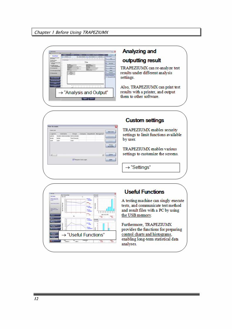
Operations available with TRAPEZIUMX, and how to use this Guide
The TRAPEZIUMX software enables you to easily and quickly execute various test operations, such as setup, test execution, and data analysis and output.
The operations available with TRAPEZIUMX, and how to use this Guide are described below.
Chapter 1 Before Using TRAPEZIUMX
12
User’s Guide
13
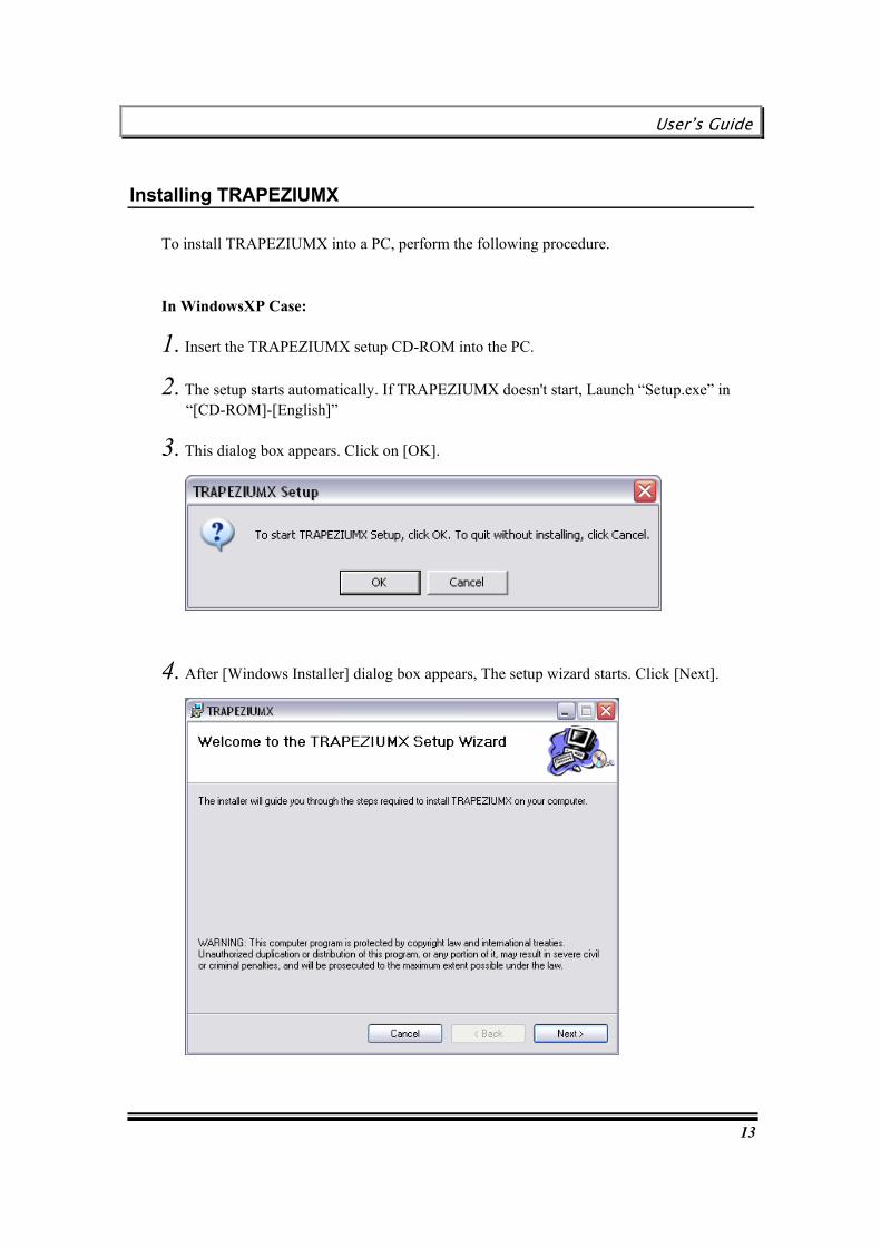
Installing TRAPEZIUMX
To install TRAPEZIUMX into a PC, perform the following procedure.
In WindowsXP Case:
1. Insert the TRAPEZIUMX setup CD-ROM into the PC.
2. The setup starts automatically. If TRAPEZIUMX doesn't start, Launch “Setup.exe” in “[CD-ROM]-[English]”
3. This dialog box appears. Click on [OK].
4. After [Windows Installer] dialog box appears, The setup wizard starts. Click [Next].

Chapter 1 Before Using TRAPEZIUMX
14
5. Set installation folder.
If you want to change the installation folder, Click [Browse]. The browse dialog box appears. Set installation folder.
6. Click [Next].
7. The installation begins. Click [Next].

User’s Guide
15
8. It is installing TRAPEZIUMX. Wait for a while.
9. If “Software Installation” dialog box displayed, Click [Continue Anyway].

Chapter 1 Before Using TRAPEZIUMX
16
10. This dialog box appears. Click on [Close].
11. Click [OK], This completes the setup procedure.
User’s Guide
17
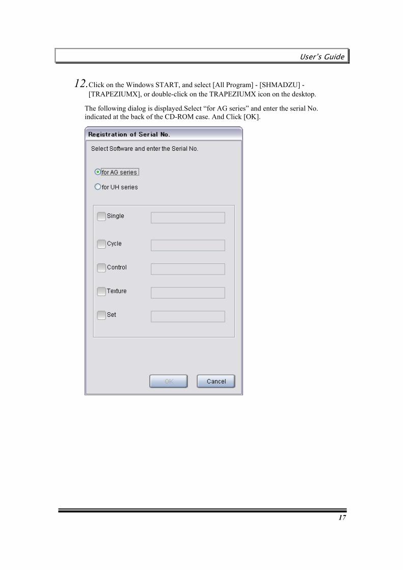
12.Click on the Windows START, and select [All Program] - [SHMADZU] - [TRAPEZIUMX], or double-click on the TRAPEZIUMX icon on the desktop.
The following dialog is displayed.Select “for AG series” and enter the serial No. indicated at the back of the CD-ROM case. And Click [OK].
Chapter 1 Before Using TRAPEZIUMX
18
In WindowsVista, Windows7 Case:
1. Insert the TRAPEZIUMX setup CD-ROM into the PC.
2. Select [Wscript.exe] in the displayed dialog. If the dialog isn't displayed, Launch “Setup.exe” in “[CD-ROM]-[English]”
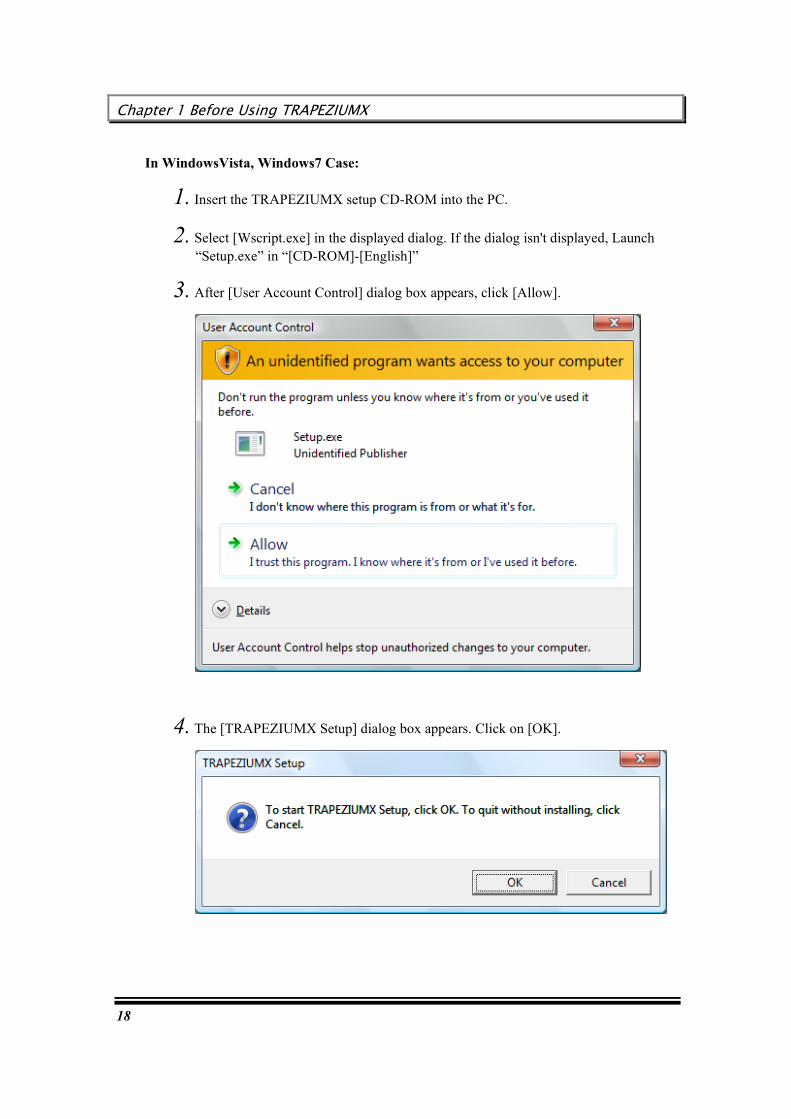
3. After [User Account Control] dialog box appears, click [Allow].
4. The [TRAPEZIUMX Setup] dialog box appears. Click on [OK].
User’s Guide
19
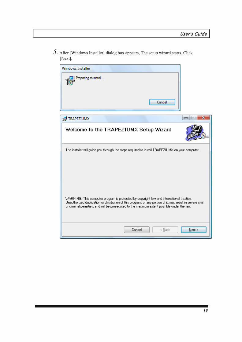
5. After [Windows Installer] dialog box appears, The setup wizard starts. Click [Next].

Chapter 1 Before Using TRAPEZIUMX
20
6. Set installation folder.
If you want to change the installation folder, Click [Browse]. The browse dialog box appears. Set installation folder.

User’s Guide
21
7. Click [Next].
8. The installation begins. Click [Next].
9. It is installing TRAPEZIUMX. Wait for a while.

Chapter 1 Before Using TRAPEZIUMX
22
10. Click on [Install].
11. This dialog box appears. Click on [Close].
12. Click [OK], This completes the setup procedure.

User’s Guide
23
13. Click on the Windows START, and select [All Program] - [SHMADZU] - [TRAPEZIUMX], or double-click on the TRAPEZIUMX icon on the desktop.
The following dialog is displayed.Select “for AG series” and enter the serial No. indicated at

Chapter 1 Before Using TRAPEZIUMX
24
Connection to The testing machine
A setting necessary to connect the testing machine with the PC is done according to the following procedures if the USB Driver is not installed when the installing of TRAPEZIUMX is finished.
If The testing machine is AG-X,AGS-X,EZ-X Series, install USB Driver. If The testing machine isn't AG-X,AGS-X,EZ-X Series, After starting TRAPEZIUMX, Confirm COM port of RS-232C (Recommended Standard 232C).
RRReeelllaaattteeeddd kkkeeeyyywwwooorrrddd : “Starting TRAPEZIUMX”
If the testing machine is AG-X,AGS-X,EZ-X Series
1. Turning power of the testing machine ON. And connect PC with the testing machine with the USB cable of the attachment.
2. [Found New Hardware Wizard] dialog box is automatically displayed.
If the dialog isn't displayed, launch “DPInst.exe” in “C:\Program Files\SHIMADZU\TRAPEZIUMX\USBDRV\x86”. After this step, refer to step 10. If OS is 64bit, launch “DPInst64.exe” in “C:\Program Files\SHIMADZU\TRAPEZIUMX\USBDRV\x64”. After this step, refer to step 10.
User’s Guide
25
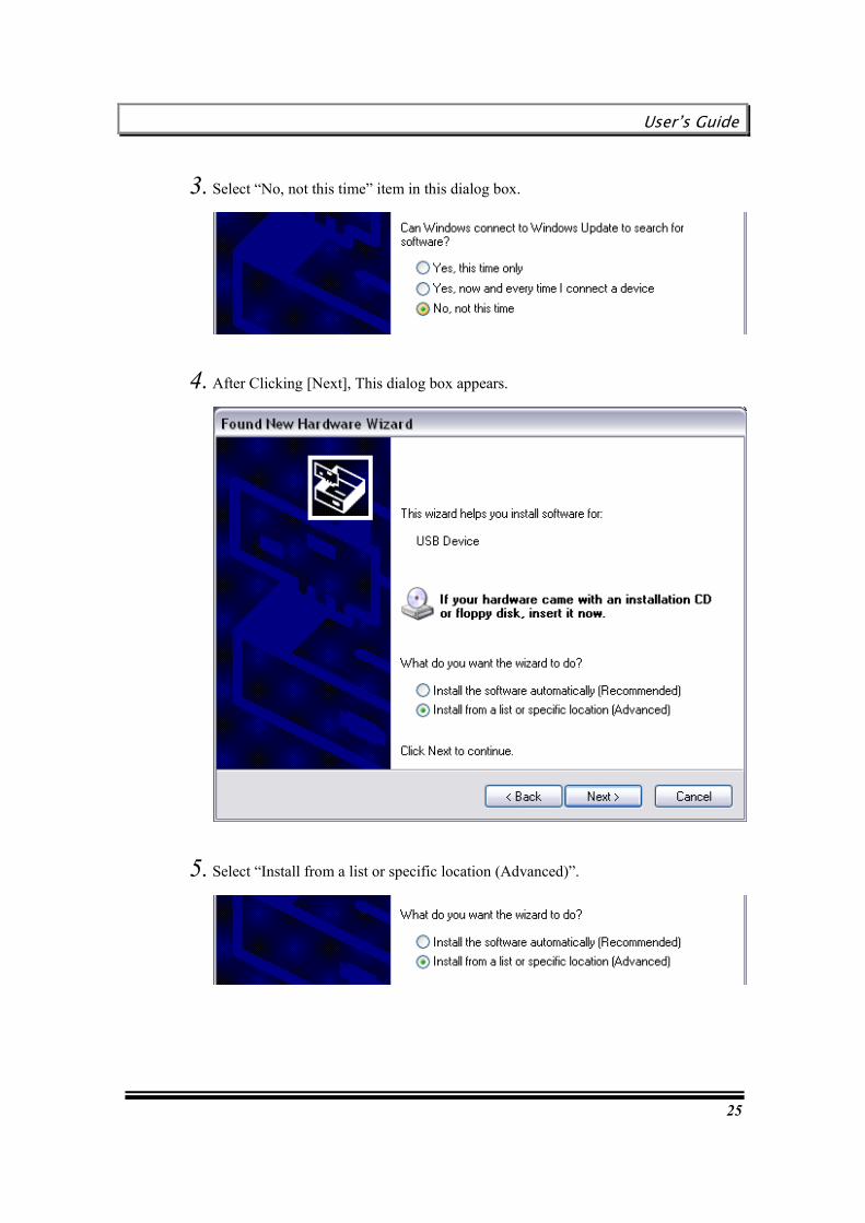
3. Select “No, not this time” item in this dialog box.
4. After Clicking [Next], This dialog box appears.
5. Select “Install from a list or specific location (Advanced)”.

Chapter 1 Before Using TRAPEZIUMX
26
6. After Clicking [Next], This dialog box appears.
7. Select “Search for the best driver in these locations”.
C:\Program Files\SHIMADZU\TRAPEZIUMX\USBDRV\x86

User’s Guide
27
8. The check on “Search removable media (floppy, CD-ROM…)” is removed, and “Include this location in the search” is checked.
If OS is 64bit, set “C:\Program Files\SHIMADZU\TRAPEZIUMX\USBDRV\x64”.
9. If an initial value of “Include this location in the search” is not “C:\Program Files\SHIMADZU\TRAPEZIUMX\USBDRV\x86”, Clicking [Browse], Set “C:\Program Files\SHIMADZU\TRAPEZIUMX\USBDRV\x86”. And click [OK]. If OS is 64bit, set “C:\Program Files\SHIMADZU\TRAPEZIUMX\USBDRV\x64”.
10. After Clicking [Next], This dialog box appears.
C:\Program Files\SHIMADZU\TRAPEZIUMX\USBDRV\x86

Chapter 1 Before Using TRAPEZIUMX
28
11. Click [Continue Anyway].
12. It is installing USB driver. Wait for a while.
13. Click [Finish], This completes the installing procedure.
User’s Guide
29
Starting TRAPEZIUMX
1. Click on the Windows START, and select [All Program] - [SHMADZU] - [TRAPEZIUMX], or double-click on the TRAPEZIUMX icon on the desktop.
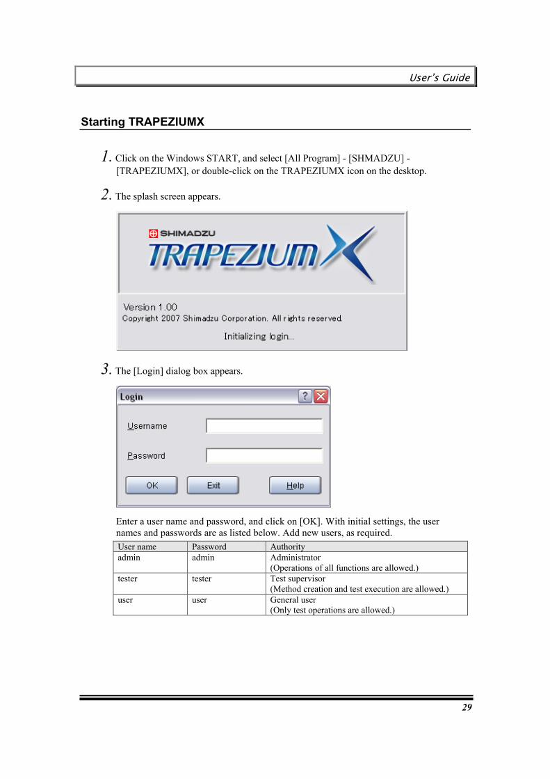
2. The splash screen appears.
3. The [Login] dialog box appears.
Enter a user name and password, and click on [OK]. With initial settings, the user names and passwords are as listed below. Add new users, as required. User name Password Authority admin admin Administrator
(Operations of all functions are allowed.) tester tester Test supervisor
(Method creation and test execution are allowed.) user user General user
(Only test operations are allowed.)

Chapter 1 Before Using TRAPEZIUMX
30
4. When you start this software for the first time with registration of several testing machines, select the type of testing machine to be used, and the machine number. Enter the machine number indicated on the machine number label (“I3XXXXXX”) affixed to the testing machine.
Click on [OK].
* After a new testing machine is registered, close TRAPEZIUMX once, and then perform the above procedure from Step 1 again.
5. When the software is started for the first time, a dialog box appears that asks whether or not to use the statistical process control function. To use the statistical process control function, click [Yes].
RRReeelllaaattteeeddd kkkeeeyyywwwooorrrddd : "Using Statistical Process Control Function"

User’s Guide
31
5. Click on [OK]. Then, the [TRAPEZIUMX Home] window appears.
Closing TRAPEZIUMX
Select [File] - [Exit]. If there is a change in the file, a confirmation message appears.
Alternatively, you may click on [Exit] in the [TRAPEZIUMX Home] window.
Chapter 1 Before Using TRAPEZIUMX
32
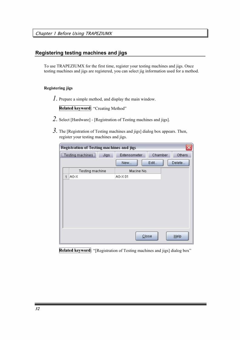
Registering testing machines and jigs
To use TRAPEZIUMX for the first time, register your testing machines and jigs. Once testing machines and jigs are registered, you can select jig information used for a method.
Registering jigs
1. Prepare a simple method, and display the main window.
RRReeelllaaattteeeddd kkkeeeyyywwwooorrrddd : “Creating Method”
2. Select [Hardware] - [Registration of Testing machines and jigs].
3. The [Registration of Testing machines and jigs] dialog box appears. Then, register your testing machines and jigs.
RRReeelllaaattteeeddd kkkeeeyyywwwooorrrddd : “[Registration of Testing machines and jigs] dialog box”

User’s Guide
33
[Execution of Test]
[Execution of Test] provides test execution procedures and various test operations.

Chapter 2 Execution of Test
34
Chapter 2 Execution of Test
This chapter describes the basic procedure for executing test with TRAPEZIUMX.
Step 1: Turning power ON
Step 2: Preparation for test execution
Step 3: Executing test
Step 4: Saving test result
Operations available during test execution
Restoring data in emergency (Backup function)

User’s Guide
35
Step 1: Turning power ON
First, the operating procedure from power-ON to start of TRAPEZIUMX is described below.
1. Turn ON the testing machine power supply.
2. Turn ON the PC power supply.
3. Double-click on the icon on the desktop to start TRAPEZIUMX.
4. After entry of a user name and password, the [TRAPEZIUMX Home] window appears.
Chapter 2 Execution of Test
36
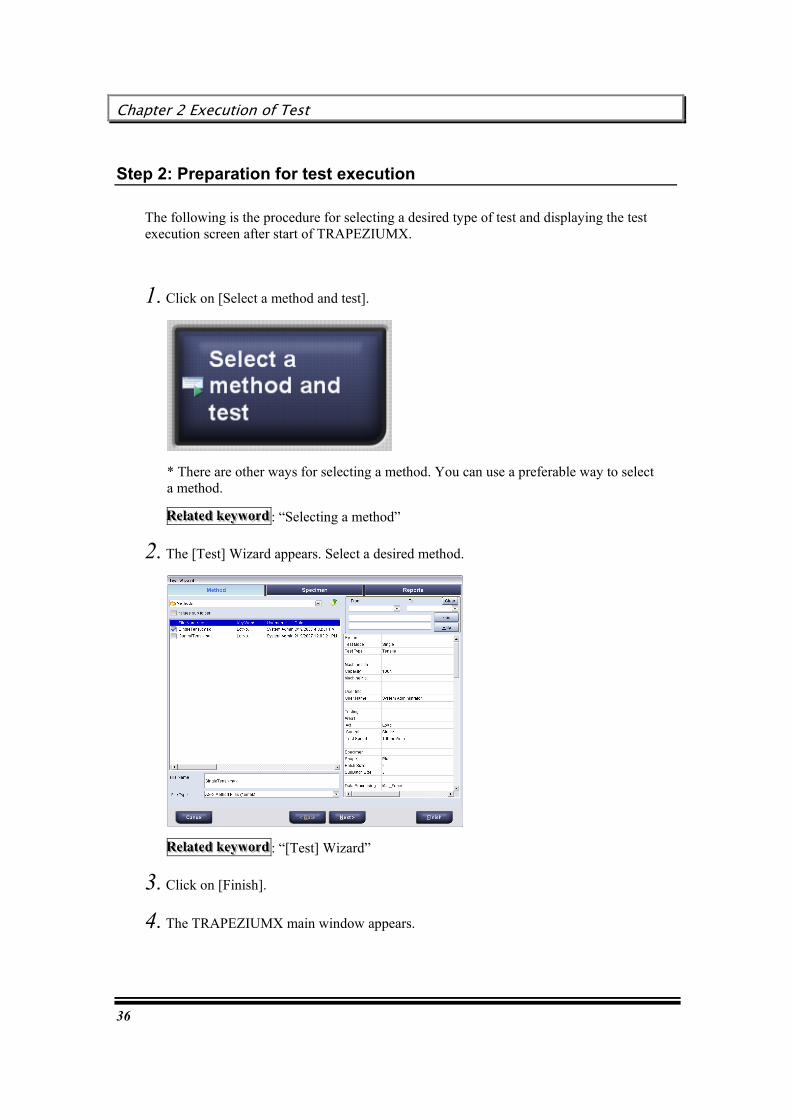
Step 2: Preparation for test execution
The following is the procedure for selecting a desired type of test and displaying the test execution screen after start of TRAPEZIUMX.
1. Click on [Select a method and test].
* There are other ways for selecting a method. You can use a preferable way to select a method.
RRReeelllaaattteeeddd kkkeeeyyywwwooorrrddd : “Selecting a method”
2. The [Test] Wizard appears. Select a desired method.
RRReeelllaaattteeeddd kkkeeeyyywwwooorrrddd : “[Test] Wizard”
3. Click on [Finish].
4. The TRAPEZIUMX main window appears.

User’s Guide
37
Step 3: Executing test
After the preparations for test execution are completed, TRAPEZIUMX can execute tests continuously with specimens as many as required.
The test execution procedure is as follows.
1. Prepare a required number of specimens.
2. Move the testing machine to the specimen mounting position.
Click the mouse right button in the blue area.
3. Mount the first specimen to the testing machine.
4. Press [ ] on the testing machine, or in the software.
Chapter 2 Execution of Test
38
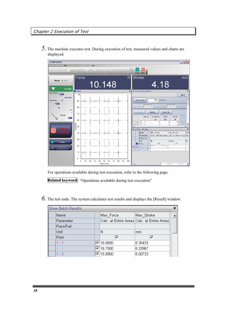
5. The machine executes test. During execution of test, measured values and charts are displayed.
For operations available during test execution, refer to the following page.
RRReeelllaaattteeeddd kkkeeeyyywwwooorrrddd : “Operations available during test execution”
6. The test ends. The system calculates test results and displays the [Result] window.

User’s Guide
39
7. Return the testing machine to the original position.
8. Mount the second specimen to the testing machine.
9. Repeat the above Step 4 through Step 7, for the specimens as many as prepared.
HHHiiinnnttt
Test results can be printed or output to other software at an arbitrary timing.
RRReeelllaaattteeeddd kkkeeeyyywwwooorrrddd : “Result Analysis and Output”

Chapter 2 Execution of Test
40
Step 4: Saving test result
Test results can be saved in a PC. The saving procedure and subsequent procedures are as follows.
1. Select [File] - [Save as] - [Test].
2. The [Save As Test] dialog box appears.
3. Enter a file name, and click on [Save].
HHHiiinnnttt
After completion of tests for all registered specimens, you can continue tests in various ways.
RRReeelllaaattteeeddd kkkeeeyyywwwooorrrddd : “[Save As Test] dialog box”
RRReeelllaaattteeeddd kkkeeeyyywwwooorrrddd : “Continuing test after completion of test”

User’s Guide
41
Operations available during test execution
During execution of test, you cannot execute most operations, because the system executes high-speed communication with the testing machine. However, the following operations are enabled.
In addition to the above, the following operations are also enabled.
- Removing extensometer
- Starting high-speed sampling from a desired position(for AG-IS and EZGraph only)
RRReeelllaaattteeeddd kkkeeeyyywwwooorrrddd : “Setting Quick Panel”
Chapter 2 Execution of Test
42
Restoring data in emergency (Backup function)
If the PC abruptly malfunctions, or if you have closed the software without saving data, the system can restore the previous test data.
Data restoring procedure
1. Select [File] - [Open] - [Test]. The [Open Test] dialog box appears.
RRReeelllaaattteeeddd kkkeeeyyywwwooorrrddd : “[Open Test] dialog box”
2. Go to the [BackUp] folder.
3. Select the [BackUpData.xt**] file, and click on [Open].
4. The test result will be displayed in the main window. Save the result.

User’s Guide
43
Amount of data that can be saved or controlled
If the amount of data from test measurement results increases too much, the software may run extremely slowly or become unstable.
In particular, if performing tests with short sampling intervals, tests performed over long periods, tests involving a large number of samples, and so on, make sure that none of the following limitations apply.
■ Limitations
The file size maximum capacity for retaining measurement data as test results is 500 MB.
500 MB of data is roughly equivalent to the following.
Sampling Interval Total Measurement Time 0.2 msec Approx. 31 minutes 1 msec Aprox. 160 minutes 10 msec Approx. 1600 minutes (approx. 26.6 hours) 100 msec Approx. 26.6 hours (approx. 11days)
Notes:
The sampling interval settings available for specifying in test conditions varies depending on the number of test specimens. For more details, see "Samplings" in the Software Reference Manual.
The above values were measured when only [Force] and [Stroke] are selected for the test sensor type.
If testing multiple specimens, use the above as a guideline for total measurement time.
If close to reaching the above limits, go ahead and use the current file, but do not continue performing additional tests. Create a new file before performing the test again.
Note
Using extensometer, width, or other sensors will increase the amount of data retained and may shorten the estimated times indicated in the table above before reaching the capacity limit.
If performing long tests or tests with short sampling intervals or large quantities, save test results in a file as often as possible and confirm the file sizes.

About This Guide
44
This page is intentionally left blank.

User’s Guide
45
Chapter 3 How to Use Test Execution Functions
TRAPEZIUMX provides many functions that enable users to flexibly execute routine test operations. This chapter describes various test execution functions.
Selecting a method
Continuing test after completion of test
Entering specimen sizes
Protecting specimens against damage before test
Returning the testing machine to the original position
Re-test
Adding specimens
Executing test for a new lot under same conditions
Deleting a line for specimen yet to be tested
Changing order of specimens
Executing scheduled task

Chapter 3 How to Use Test Execution Functions
46
Selecting a method
Before executing of test, select a method from prepared items.
TRAPEZIUMX provides several ways for method selection. Use a suitable way by referring to the following flowchart.
RRReeelllaaattteeeddd kkkeeeyyywwwooorrrddd : “[Method] Wizard”
User’s Guide
47
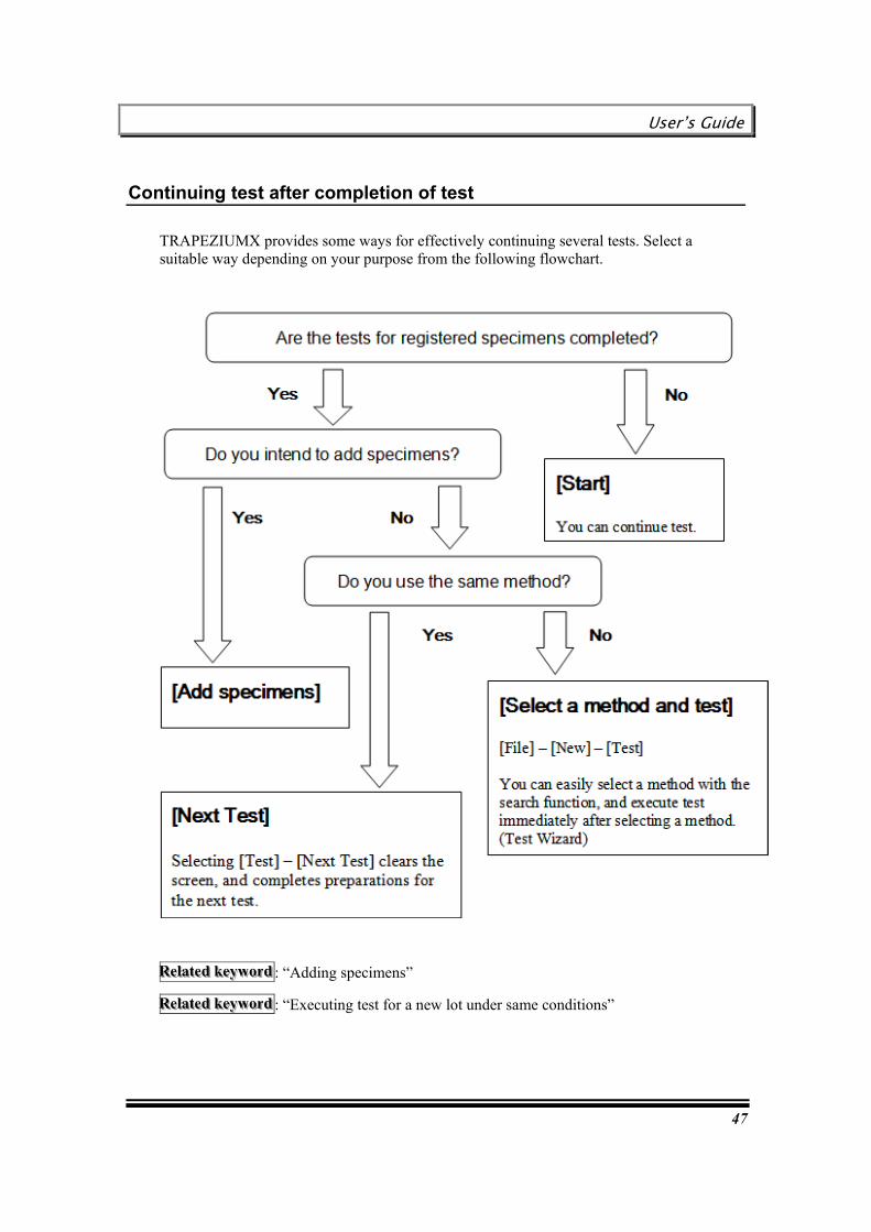
Continuing test after completion of test
TRAPEZIUMX provides some ways for effectively continuing several tests. Select a suitable way depending on your purpose from the following flowchart.
RRReeelllaaattteeeddd kkkeeeyyywwwooorrrddd : “Adding specimens”
RRReeelllaaattteeeddd kkkeeeyyywwwooorrrddd : “Executing test for a new lot under same conditions”
Chapter 3 How to Use Test Execution Functions
48
Entering specimen sizes
For example, you can enter specimen sizes for the following purposes.
- For stress or strain calculation
- For recording specimen data together with test result
When can specimen sizes be entered?
- Specimen sizes can be entered at any time (before and after test).
Which window is to be used for entry of specimen sizes?
- To change only specimen sizes easily
[Specimen Sizes]
Selecting [Test] - [Specimen Sizes] displays the entry screen.
- To change specimen sizes directly in the main window (for frequent changes)
[Quick Setting Panel]
The entry screen is always displayed on the main screen.
- To change specimen sizes together with other conditions
[Reanalyze]
Selecting [Test] - [Reanalyze] displays the [Method] Wizard.
RRReeelllaaattteeeddd kkkeeeyyywwwooorrrddd : “[Test] Wizard - [Specimen Sizes] Dialog Box”
RRReeelllaaattteeeddd kkkeeeyyywwwooorrrddd : “[Quick Setting Panel] Dialog Box”
RRReeelllaaattteeeddd kkkeeeyyywwwooorrrddd : “[Method] Wizard - [System] Dialog Box”
User’s Guide
49
Protecting specimens against damage before test
With the specimen protection function, you can prevent damage to specimens under excessive load before execution of test.
Application of this function
When the specimen is extremely fragile
Perform the following procedure
1. Display the main screen, and make preparations for test.
2. Select [Test] - [Test Control] - [Force Zero Hold].
3. The testing machine automatically moves to hold the force at “0”.
4. You can start a test by pressing [Start].
HHHiiinnnttt
Pressing [Stop] cancels the specimen protection function.
Chapter 3 How to Use Test Execution Functions
50
Returning the testing machine to the original position
After completion of test with a single specimen, the testing machine can be returned to the test starting position.
To return the machine manually
Select [Test] - [Test Control] - [Return].
To return the machine automatically after completion of test
Select [Return] in [Break and Limit Action] on the method wizard screen.
RRReeelllaaattteeeddd kkkeeeyyywwwooorrrddd : “[Method] Wizard - [Testing] Dialog Box”
User’s Guide
51
Re-test
Application of this function
If you intend to re-test a specimen after an error, you can re-execute the test with the [Re-Test] function. The test result will be overwritten in the same place where an error occurred.
Perform the following procedure
1. In the result window, double-click on the left end column for the specimen to be re-tested.
HHHiiinnnttt
The re-test function can be also enabled by selecting [Test] ? [Re-Test], or by clicking the mouse right button on the target specimen and selecting [Re-Test this specimen].
2. The [Re-Test] dialog box appears.
3. Enter the specimen sizes as required, and click on [OK].
4. The selected result will be cleared, and the system prepares for re-test.
5. After the re-test is executed, the result will be displayed in the same column.
6. Select [Test] - [Test Control] - [Force Zero Hold].
Chapter 3 How to Use Test Execution Functions
52
Adding specimens
After completion of tests for all registered specimens, the number of specimens can be added.
Changing batch size and sub batch size
- [Specimen Sizes]
Selecting [Test] - [Specimen Sizes] displays the entry screen.
Or
- [Re-analyze]
Selecting [Test] - [Re-analyze] displays the Method Wizard.
RRReeelllaaattteeeddd kkkeeeyyywwwooorrrddd : “[Test] Wizard - [Specimen Sizes] Dialog Box”
RRReeelllaaattteeeddd kkkeeeyyywwwooorrrddd : “[Method] Wizard - [System] Dialog Box”
Inserting a single specimen into a desired place
When the result window is displayed, perform the following procedure.
1. Click the mouse right button on the line above the specimen inserting position.
2. Select [Insert]. A specimen is added below the selected line.
Adding a single specimen to the end of batch
When the result window is displayed, perform the following procedure.
1. Click the mouse right button on a specimen of the batch to which a specimen is to be added.
2. Select [Add Specimen]. A specimen is added to the end of the selected batch.

User’s Guide
53
Executing test for a new lot under same conditions
Application of this function
With the [Next Test] function, you can execute new tests for the same number of specimens under the same conditions, after tests for all registered specimens are completed.
Perform the following procedure
1. Select [Test] - [Next Test].
2. The chart and result on the screen will be cleared, and the system prepares for new test.

Chapter 3 How to Use Test Execution Functions
54
Deleting a line for specimen yet to be tested
Application of this function
If the number of tests completed is less than the registered number, a line for specimen yet to be tested can be deleted from the screen.
When the result window is displayed, perform the following procedure
Perform the following procedure
1. Click the mouse right button on the line to be deleted.
2. Select [Delete this specimen]. The selected line will be deleted.
HHHiiinnnttt
During report printing, a line for specimen yet to be tested will not be printed, even if the line is not deleted.
HHHiiinnnttt
The line for the next test will not be deleted.

User’s Guide
55
Changing order of specimens
Application of this function
If the order of test is incorrect, or if a specimen of a lower number is delivered to be tested later, the order of test results can be changed afterward.
Perform the following procedure
1. Click on [Specimen Name] for the specimen whose order is to be changed.
2. Drag the mouse cursor to the edge of the cell that indicates the specimen name. Then, the cursor changes to the “+” mark.
3. With the mouse left button held down, drag it to the destination line.
4. After the mouse button is released, a confirmation message appears.
5. Click on [Yes]. Then, the specimen will move to the destination line.
HHHiiinnnttt
You cannot move a specimen to the top line.
Chapter 3 How to Use Test Execution Functions
56
Executing scheduled task
You can call registered methods in specified order to execute tests.
Application of this function
This function can be used when one person creates test schedule and another person executes the scheduled task.
Once daily test schedule and methods are determined first, an operator can execute tests in sequence according to the schedule.
Perform the following procedure
1. Select [File] - [New] - [Executes scheduled tasks].
2. The system automatically calls the methods registered in the schedule, and prepares for test execution.
HHHiiinnnttt : How to check schedule
Select [Tools] - [Task &Scheduler]. Then, the [Settings of Test Schedule] dialog box appears.

User’s Guide
57
[Creating Method]
[Creating Method] provides various examples of the procedures for creating methods (= settings required for test execution).
Chapter 4 Flow of Method Creating and Editing Operations
58
Chapter 4 Flow of Method Creating and Editing Operations
This chapter describes the flow of operations for creating a new method, and for edition of an existing method file.
Creating a new method
Editing an existing method file

User’s Guide
59
Creating a new method
This section describes the flow of operation for creating a new method.
1. Start TRAPEZIUMX.
Double-click on the icon on the desktop to start TRAPEZIUMX. The [TRAPEZIUMX Home] window appears.
2. Click on [ ]. Then, [Method Wizard] appears.
HHHiiinnnttt
You can perform the same operation by selecting the following commands or button when the main window is displayed.
Select [File] - [New] - [Method]. Select [New] - [Method] on the tool bar. Select [Create a new method] on the navigation bar.

Chapter 4 Flow of Method Creating and Editing Operations
60
Click on the tab to be set up, or click on [Next] or [Back], and specify each item.
3. Click on any of the following buttons depending on the subsequent operation.
- To execute test immediately under the current method settings: Click on
[ ].
- To return to the Home window after saving the method settings: Click on
[ ].
- To quit the method creating procedure and return to the Home window: Click on
[ ].

User’s Guide
61
Editing an existing method file
This section describes the flow of operation for opening and editing an exiting method file.
1. Start TRAPEZIUMX.
Double-click on the icon on the desktop to start TRAPEZIUMX. The [TRAPEZIUMX Home] window appears.
2. Click on [ ]. Then, [Method Wizard] appears.
HHHiiinnnttt
You can perform the same operation by selecting the following commands or button when the main window is displayed.
Select [File] - [Open] - [Method]. Select [Open] - [Method] on the tool bar. Select [Open a method] on the navigation bar.

Chapter 4 Flow of Method Creating and Editing Operations
62
Click on the tab to be set up, or click on [Next] or [Back], and specify each item.
3. Click on any of the following buttons depending on the subsequent operation.
- To execute test immediately under the current method settings: Click on
[ ].
- To return to the Home window after saving the method settings: Click on
[ ].
- To quit the method creating procedure and return to the Home window: Click on
[ ].

User’s Guide
63
Chapter 5 Creating Single Test Method
This chapter describes the procedures for creating a method for the tests that can be executed with the single test software.
Creating a tensile test method
Creating a compression test method
Creating a bending test method
Creating a peel test method
Creating a creep test method

Chapter 5 Creating Single Test Method
64
Creating a simple tensile test method
This section describes the basic flow of method creating operation, showing the procedure for creating a method for tensile test.
HHHiiinnnttt
For details of each dialog box, refer to [TRAPEZIUMX Software Reference Manual].
User’s Guide
65
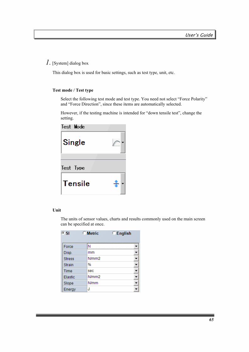
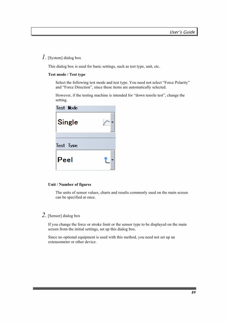
1. [System] dialog box
This dialog box is used for basic settings, such as test type, unit, etc.
Test mode / Test type
Select the following test mode and test type. You need not select “Force Polarity” and “Force Direction”, since these items are automatically selected.
However, if the testing machine is intended for “down tensile test”, change the setting.
Unit
The units of sensor values, charts and results commonly used on the main screen can be specified at once.
Chapter 5 Creating Single Test Method
66
2. [Sensor] dialog box
If you change the force or stroke limit or the sensor type to be displayed on the main screen from the initial settings, set up this dialog box.
Since no optional equipment is used with this method, you need not set up an extensometer or other device.
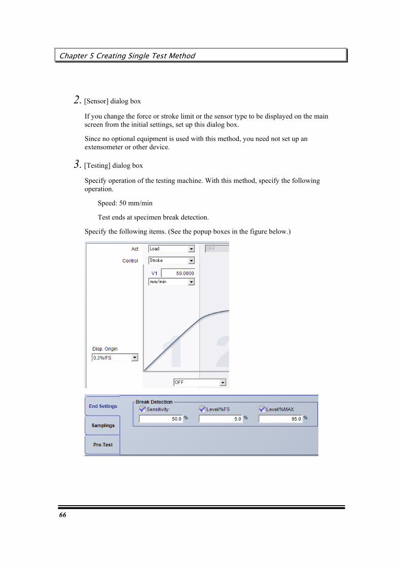
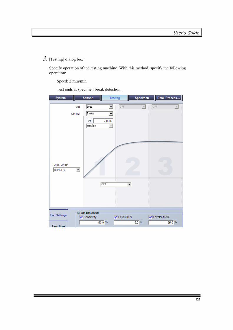
3. [Testing] dialog box
Specify operation of the testing machine. With this method, specify the following operation.
Speed: 50 mm/min
Test ends at specimen break detection.
Specify the following items. (See the popup boxes in the figure below.)
User’s Guide
67
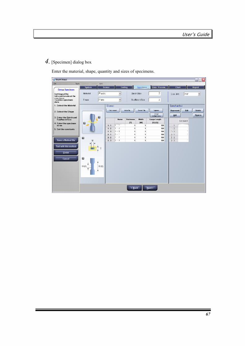
4. [Specimen] dialog box
Enter the material, shape, quantity and sizes of specimens.
Chapter 5 Creating Single Test Method
68
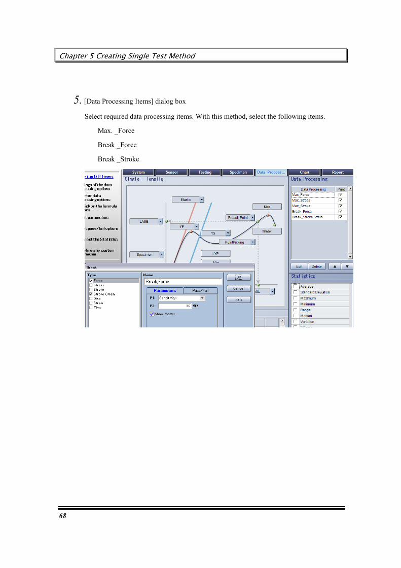
5. [Data Processing Items] dialog box
Select required data processing items. With this method, select the following items.
Max. _Force
Break _Force
Break _Stroke
User’s Guide
69
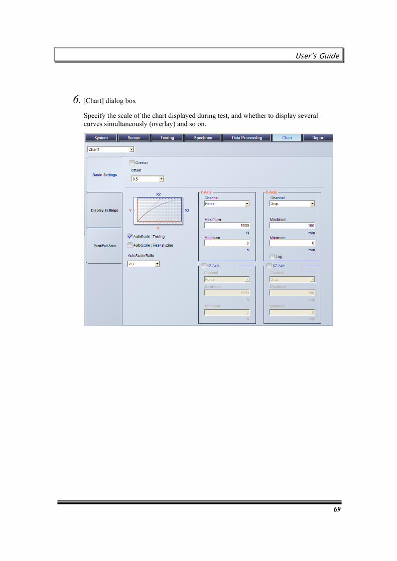
6. [Chart] dialog box
Specify the scale of the chart displayed during test, and whether to display several curves simultaneously (overlay) and so on.

Chapter 5 Creating Single Test Method
70
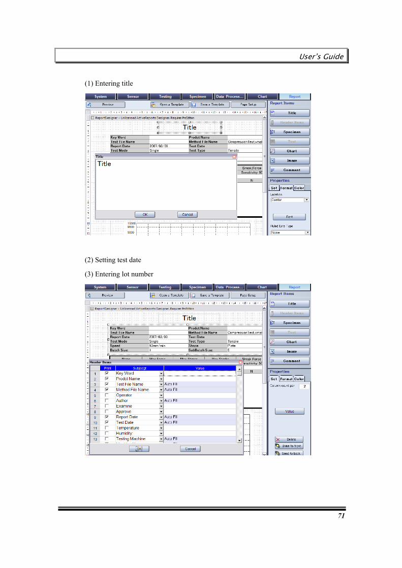
7. [Report] dialog box
Enter the information to be printed in a report, and specify the report layout.
Change the sample report displayed with the initial settings. With this method, create the following report.
Item Contents Operations available in this dialog box Title Test report Changing characters in “Title” Test date February 1, 2007 Selecting in “Header item”
Key word TPA-3561 Entering in “Header item” Specimen sizes (Already specified) None
(Automatically specified in the sample) Test result (Automatically calculated after
test) None (Automatically specified in the sample)
Chart (Displayed during test) None (Automatically specified in the sample)
User’s Guide
71
(1) Entering title
(2) Setting test date
(3) Entering lot number

Chapter 5 Creating Single Test Method
72
Creating a tensile test method using an extensometer
This section describes the flow of operation for creating a tensile test method using an extensometer.
HHHiiinnnttt
For details of each dialog box, refer to [TRAPEZIUMX Software Reference Manual].

User’s Guide
73
1. [System] dialog box
This dialog box is used for basic settings, such as test type, unit, etc.
Test mode / Test type
Select the following test mode and test type. You need not select “Force Polarity” and “Force Direction”, since these items are automatically selected.
However, if the testing machine is intended for “down tensile test”, change the setting.
Unit, Number of figures
The units of sensor values, charts and results commonly used on the main screen can be specified at once.
The number of significant digits of elastic should be specified as follows
Chapter 5 Creating Single Test Method
74
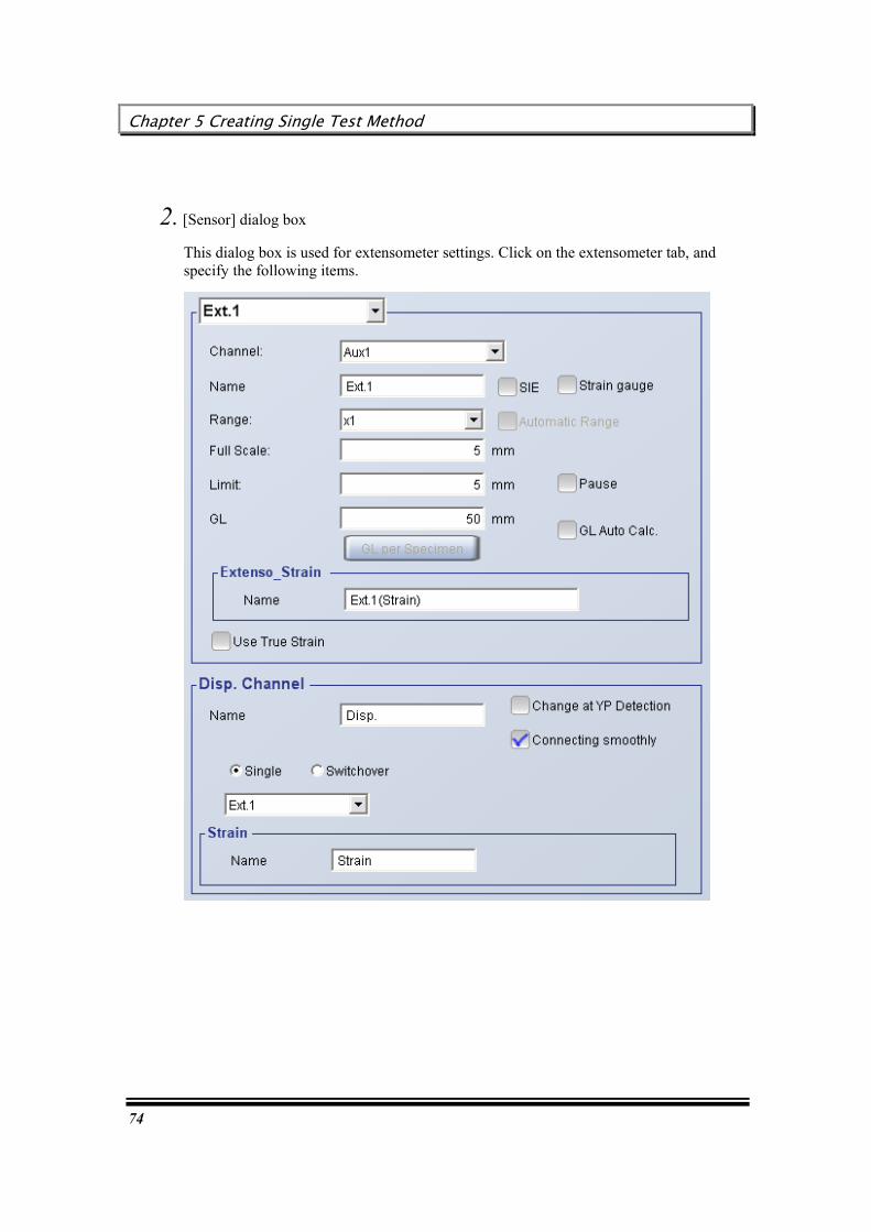
2. [Sensor] dialog box
This dialog box is used for extensometer settings. Click on the extensometer tab, and specify the following items.
User’s Guide
75
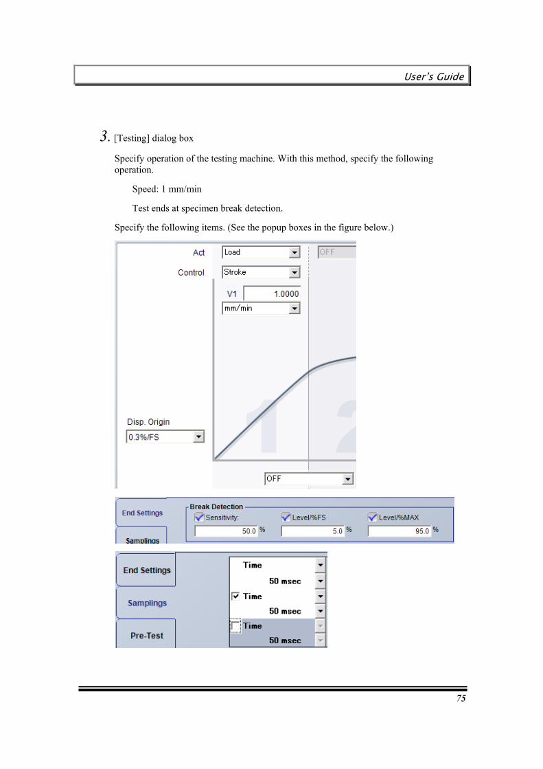
3. [Testing] dialog box
Specify operation of the testing machine. With this method, specify the following operation.
Speed: 1 mm/min
Test ends at specimen break detection.
Specify the following items. (See the popup boxes in the figure below.)

Chapter 5 Creating Single Test Method
76
4. [Specimen] dialog box
Enter the material, shape, quantity and sizes of specimens. In this example, select the settings for three batches with five specimens per lot.

User’s Guide
77
5. [Data Processing Items] dialog box
Select required data processing items. With this method, select the following item.
Elastic_Standard
In this example, Elastic is calculated in the range of 0.05% to 0.25% for “Ext.1 (Strain)”.
6. [Chart] / [Report] dialog boxes
Set up each dialog box as required.
Chapter 5 Creating Single Test Method
78
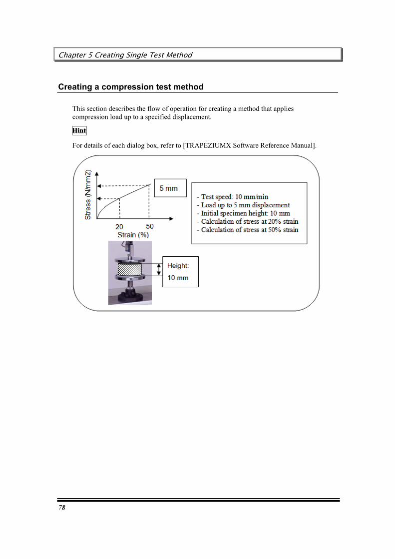
Creating a compression test method
This section describes the flow of operation for creating a method that applies compression load up to a specified displacement.
HHHiiinnnttt
For details of each dialog box, refer to [TRAPEZIUMX Software Reference Manual].

User’s Guide
79
1. [System] dialog box
This dialog box is used for basic settings, such as test type, unit, etc.
Test mode / Test type
Select the following test mode and test type. You need not select “Force Polarity” and “Force Direction”, since these items are automatically selected.
However, if the testing machine is intended for “down tensile test”, change the setting.
Unit / Number of figures
The units of sensor values, charts and results commonly used on the main screen can be specified at once.
2. [Sensor] dialog box
If you change the force or stroke limit or the sensor type to be displayed on the main screen from the initial settings, set up this dialog box.
Since no optional equipment is used with this method, you need not set up an extensometer or other device.
Chapter 5 Creating Single Test Method
80
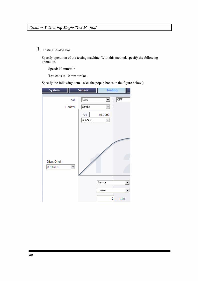
3. [Testing] dialog box
Specify operation of the testing machine. With this method, specify the following operation.
Speed: 10 mm/min
Test ends at 10 mm stroke.
Specify the following items. (See the popup boxes in the figure below.)

User’s Guide
81
4. [Specimen] dialog box
Enter the material, shape, required quantity and sizes of specimens.
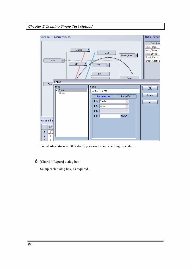
5. [Data Processing Items] dialog box
Select required data processing items. With this method, select the following items:
Stress at 20% strain
Stress at 50% strain
In this example, the stress at “20%” of “Stroke (Strain)” is calculated.
Chapter 5 Creating Single Test Method
82
To calculate stress at 50% strain, perform the same setting procedure.
6. [Chart] / [Report] dialog box
Set up each dialog box, as required.
User’s Guide
83
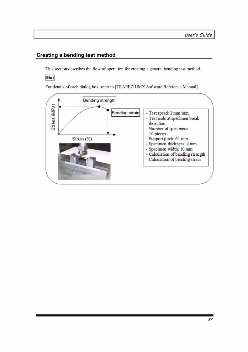
Creating a bending test method
This section describes the flow of operation for creating a general bending test method.
HHHiiinnnttt
For details of each dialog box, refer to [TRAPEZIUMX Software Reference Manual].

Chapter 5 Creating Single Test Method
84
1. [System] dialog box
This dialog box is used for basic settings, such as test type, unit, etc.
Test mode / Test type
Select the following test mode and test type. You need not select “Force Polarity” and “Force Direction”, since these items are automatically selected.
Unit
The units of sensor values, charts and results commonly used on the main screen can be specified at once. In this example, specify “MPa” for the unit of stress.
2. [Sensor] dialog box
If you change the force or stroke limit or the sensor type to be displayed on the main screen from the initial settings, set up this dialog box.
Since no optional equipment is used with this method, you need not set up an extensometer or other device.
User’s Guide
85
3. [Testing] dialog box
Specify operation of the testing machine. With this method, specify the following operation:
Speed: 2 mm/min
Test ends at specimen break detection.
Chapter 5 Creating Single Test Method
86
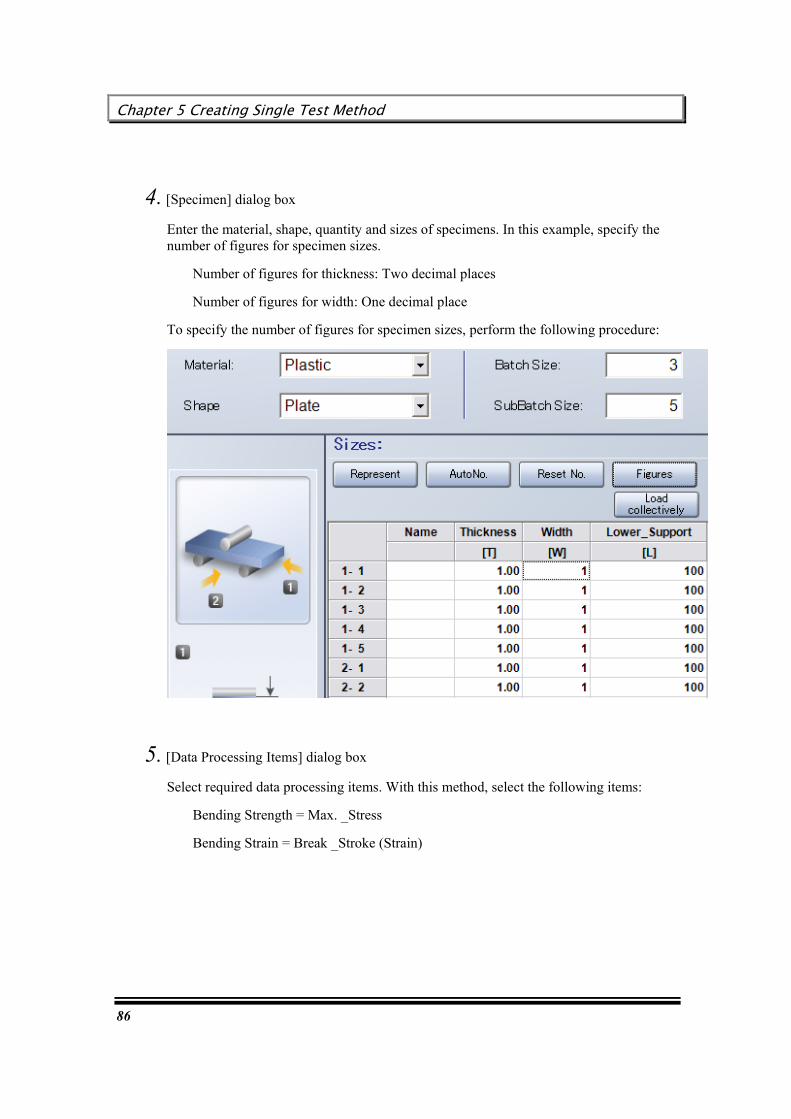
4. [Specimen] dialog box
Enter the material, shape, quantity and sizes of specimens. In this example, specify the number of figures for specimen sizes.
Number of figures for thickness: Two decimal places
Number of figures for width: One decimal place
To specify the number of figures for specimen sizes, perform the following procedure:
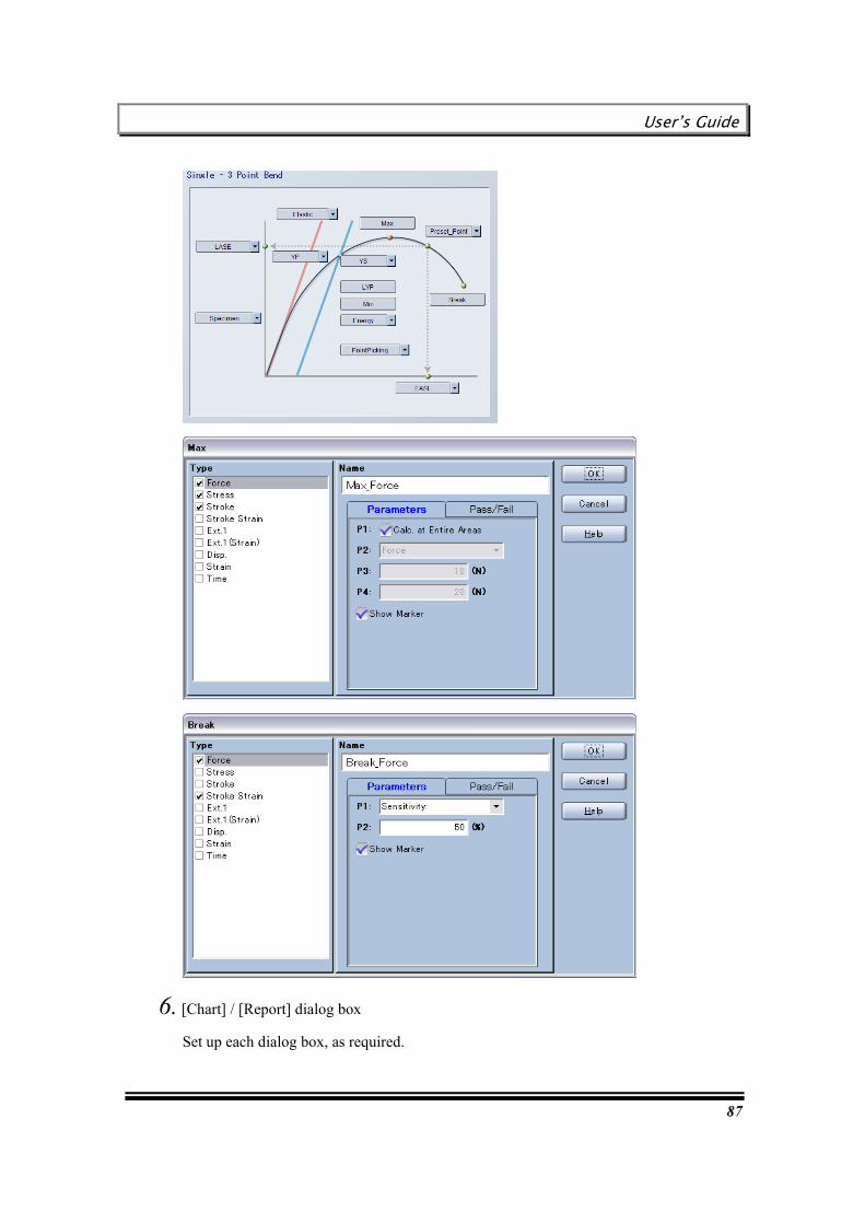
5. [Data Processing Items] dialog box
Select required data processing items. With this method, select the following items:
Bending Strength = Max. _Stress
Bending Strain = Break _Stroke (Strain)
User’s Guide
87
6. [Chart] / [Report] dialog box
Set up each dialog box, as required.
Chapter 5 Creating Single Test Method
88
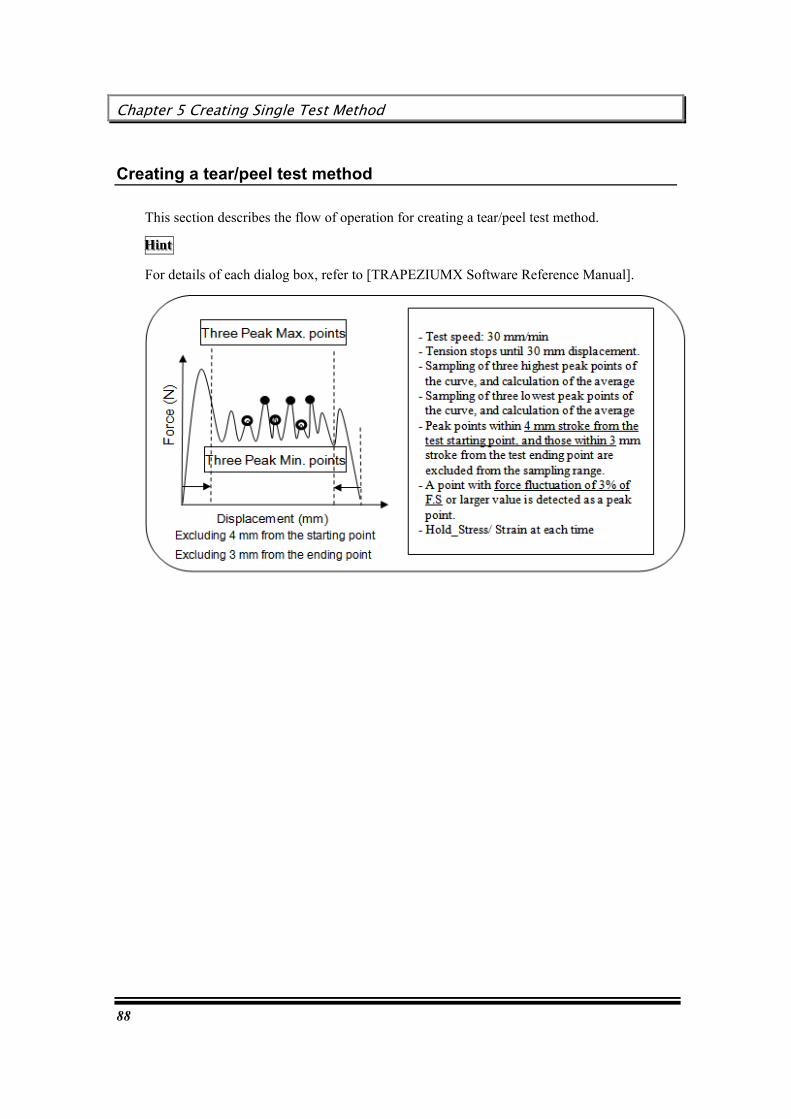
Creating a tear/peel test method
This section describes the flow of operation for creating a tear/peel test method.
HHHiiinnnttt
For details of each dialog box, refer to [TRAPEZIUMX Software Reference Manual].
User’s Guide
89
1. [System] dialog box
This dialog box is used for basic settings, such as test type, unit, etc.
Test mode / Test type
Select the following test mode and test type. You need not select “Force Polarity” and “Force Direction”, since these items are automatically selected.
However, if the testing machine is intended for “down tensile test”, change the setting.
Unit / Number of figures
The units of sensor values, charts and results commonly used on the main screen can be specified at once.
2. [Sensor] dialog box
If you change the force or stroke limit or the sensor type to be displayed on the main screen from the initial settings, set up this dialog box.
Since no optional equipment is used with this method, you need not set up an extensometer or other device.

Chapter 5 Creating Single Test Method
90
3. [Testing] dialog box
Specify operation of the testing machine. With this method, specify the following operation:
Speed: 30 mm/min
Stop at 30 mm stroke
4. [Specimen] dialog box
Enter the quantity and sizes of specimens.

User’s Guide
91
5. [Data Processing Items] dialog box
Specify the parameters required for data processing.
Three highest peak points, and average
Three lowest peak points, and average
A point with force fluctuation (sensitivity) of 3% of F.S or larger value is detected as a peak point.
Peak points within 4 mm stroke from the starting point, and those within 3 mm stroke from the ending point are excluded from the sampling range.

Chapter 5 Creating Single Test Method
92
6. [Chart] / [Report] dialog box
Set up each dialog box, as required.
User’s Guide
93
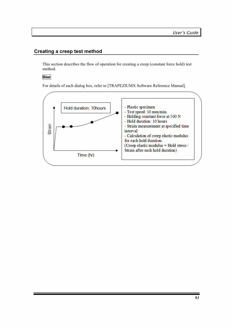
Creating a creep test method
This section describes the flow of operation for creating a creep (constant force hold) test method.
HHHiiinnnttt
For details of each dialog box, refer to [TRAPEZIUMX Software Reference Manual].

Chapter 5 Creating Single Test Method
94
1. [System] dialog box
This dialog box is used for basic settings, such as test type, unit, etc.
Test mode / Test type
Select the following test mode and test type as required. You need not select “Force Polarity” and “Force Direction”, since these items are automatically selected.
However, if the testing machine is intended for “down tensile test”, change the setting.
Unit / Number of figures
The units of sensor values, charts and results commonly used on the main screen can be specified at once.
In this example, specify “/s (non-dimensional)” as the unit of strain, and “hr (hour)” as the unit of time duration.

User’s Guide
95
2. [Sensor] dialog box
If you change the force or stroke limit or the sensor type to be displayed on the main screen from the initial settings, set up this dialog box.
Since no optional equipment is used with this method, you need not set up an extensometer or other device.
“Strain” and “duration” values can be displayed on the main screen during test execution.
Chapter 5 Creating Single Test Method
96
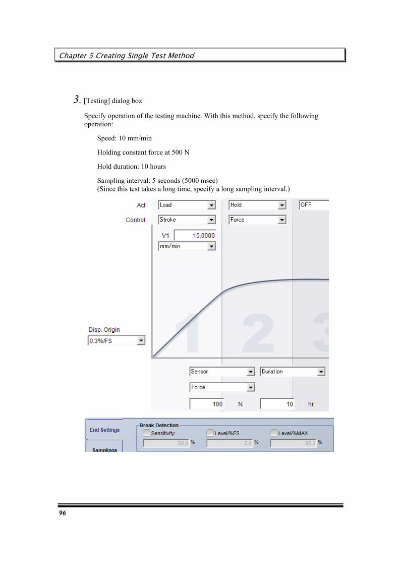
3. [Testing] dialog box
Specify operation of the testing machine. With this method, specify the following operation:
Speed: 10 mm/min
Holding constant force at 500 N
Hold duration: 10 hours
Sampling interval: 5 seconds (5000 msec) (Since this test takes a long time, specify a long sampling interval.)

User’s Guide
97
4. [Specimen] dialog box
Enter the material, shape, quantity and sizes of specimens.

Chapter 5 Creating Single Test Method
98
5. [Data Processing Items] dialog box
Select required data processing items. With this method, select the following items:
Strain after hold duration of 1, 2, 5 and 10 hours, and
creep elastic for each hold duration
This example describes how to calculate the strain after hold duration of one hour, and the creep elastic for this hold duration.

User’s Guide
99
6. [Chart] dialog box
To monitor a change in strain, specify the parameters for a “Strain - Time” chart.
7. [Report] dialog box
Set up each dialog box, as required.

Chapter 5 Creating Single Test Method
100
This page is intentionally left blank.
User’s Guide
101
Chapter 6 Creating Cycle Test Method
This chapter describes the procedure for creating a method for the tests that can be executed with the cycle test software.
Creating a simple cycle test method
Creating a cycle test method with many cycles and resistance input

Chapter 6 Creating Cycle Test Method
102
Creating a simple cycle test method
This section describes the flow of operation for creating a method for calculating hysteresis in a compression cycle test that needs preliminary load (Pre-Test).
HHHiiinnnttt
For details of each dialog box, refer to [TRAPEZIUMX Software Reference Manual].

User’s Guide
103
1. [System] dialog box
This dialog box is used for basic settings, such as test type, unit, etc.
Test mode / Test type
Select the following test mode and test type. You need not select “Force Polarity” and “Force Direction”, since these items are automatically selected.
Unit / Number of figures
The units of sensor values, charts and results commonly used on the main screen can be specified at once. For the number of figures of hysteresis, specify the number of figures of “Energy”.

Chapter 6 Creating Cycle Test Method
104
2. [Sensor] dialog box
Specify the force and stroke limits, as required.
“Cycle” is automatically added to “Sensor displayed on the main screen”. During test execution, the current cycle number is displayed.
3. [Testing] dialog box
Specify operation of the testing machine. With this method, specify the following operation:
Speed: 10 mm/min
Pre-Test: Two cycles, Up to 50 N
Actual test: One cycle, Up to 50 N
Specify the following items. (See the popup boxes in the figure below.)
User’s Guide
105
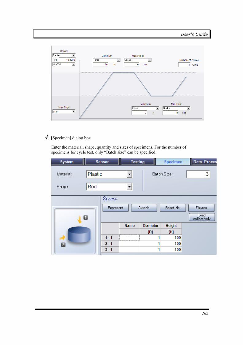
4. [Specimen] dialog box
Enter the material, shape, quantity and sizes of specimens. For the number of specimens for cycle test, only “Batch size” can be specified.

Chapter 6 Creating Cycle Test Method
106
5. [Data Processing Items] dialog box
Select required data processing items. With this method, select the following items:
Hysteresis
There is no parameter corresponding to “Hysteresis”. To specify Pass/Fail judgment criteria, mark the checkbox for “Enabled”, and enter the upper and lower limits.
6. [Chart] / [Report] dialog box
Set up each dialog box, as required.
User’s Guide
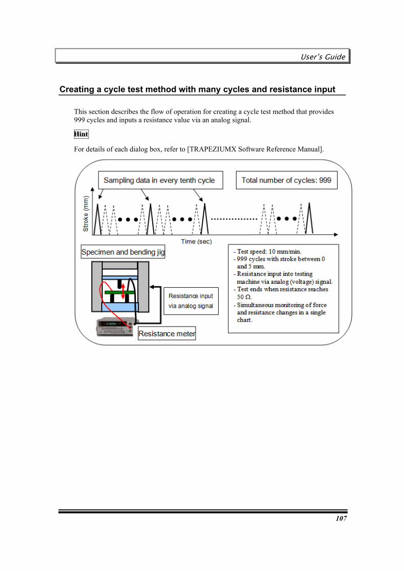
107
Creating a cycle test method with many cycles and resistance input
This section describes the flow of operation for creating a cycle test method that provides 999 cycles and inputs a resistance value via an analog signal.
HHHiiinnnttt
For details of each dialog box, refer to [TRAPEZIUMX Software Reference Manual].
Chapter 6 Creating Cycle Test Method
108
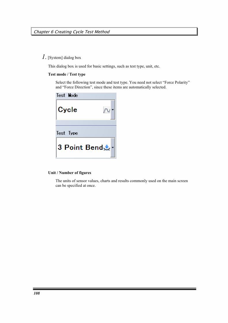
1. [System] dialog box
This dialog box is used for basic settings, such as test type, unit, etc.
Test mode / Test type
Select the following test mode and test type. You need not select “Force Polarity” and “Force Direction”, since these items are automatically selected.
Unit / Number of figures
The units of sensor values, charts and results commonly used on the main screen can be specified at once.
User’s Guide
109
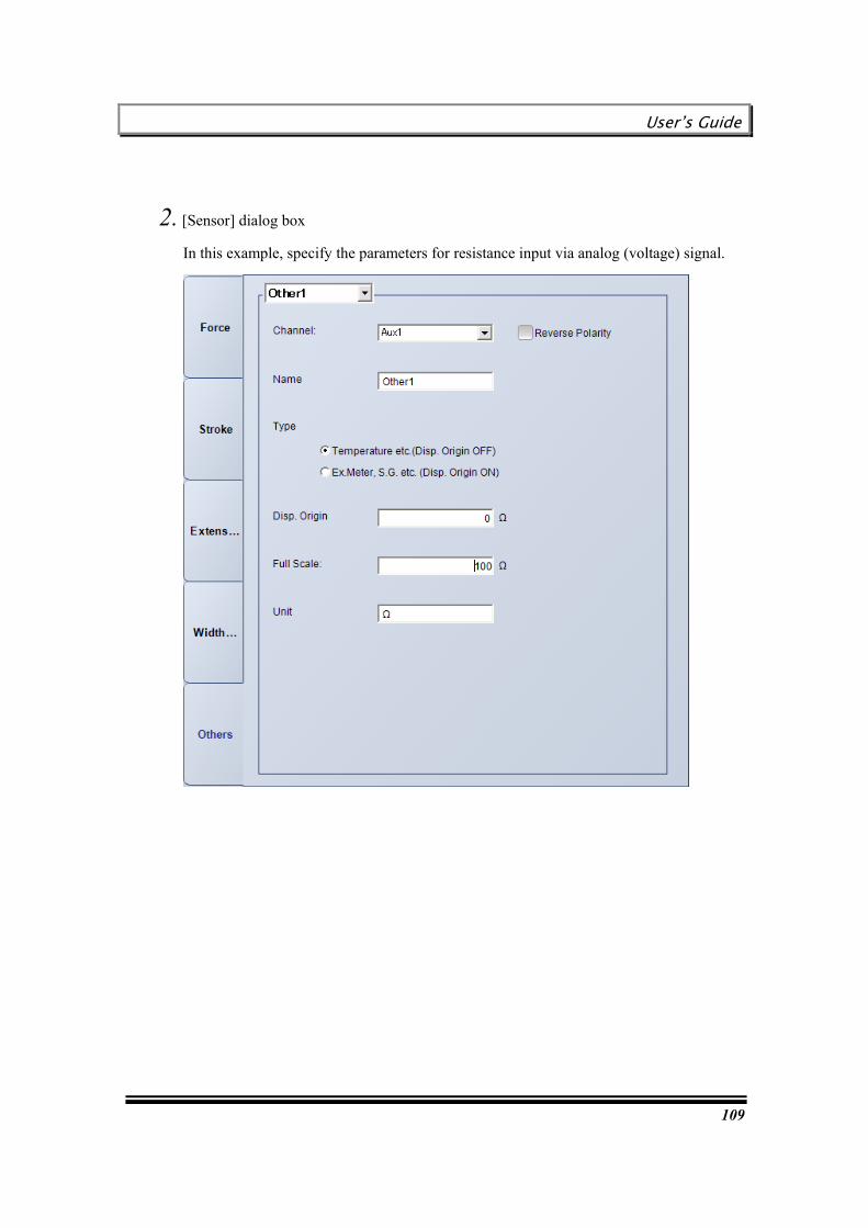
2. [Sensor] dialog box
In this example, specify the parameters for resistance input via analog (voltage) signal.

Chapter 6 Creating Cycle Test Method
110
3. [Testing] dialog box
Specify operation of the testing machine. With this method, specify the following operation:
Number of cycles: 999 cycles
MIN = 0 mm, MAX = 5 mm
Speed: 10 mm/min
Test ends at resistance of 50W.
4. [Specimen] dialog box
Enter the material, shape, quantity and sizes of specimens.

User’s Guide
111
5. Data Processing Items] dialog box
Specify the parameters to execute measurement in every tenth cycle.
For data processing item, select “Max._ Force” for each cycle.

Chapter 6 Creating Cycle Test Method
112
6. [Chart] dialog box
Specify the parameters to monitor force and resistance changes simultaneously in a single chart.
Set up a 2-axis chart as follows:
Y axis: Force (N)
Y2 axis: Resistance (W)
X axis: Time (sec)
7. [Report] dialog box
Set up this dialog box, as required.
User’s Guide
113
Chapter 7 Creating Control Test Method
This chapter describes the procedure for creating a method of the tests that can be executed with the control test software.
Creating a simple up/down test method
Creating a stepped control test method
Chapter 7 Creating Control Test Method
114
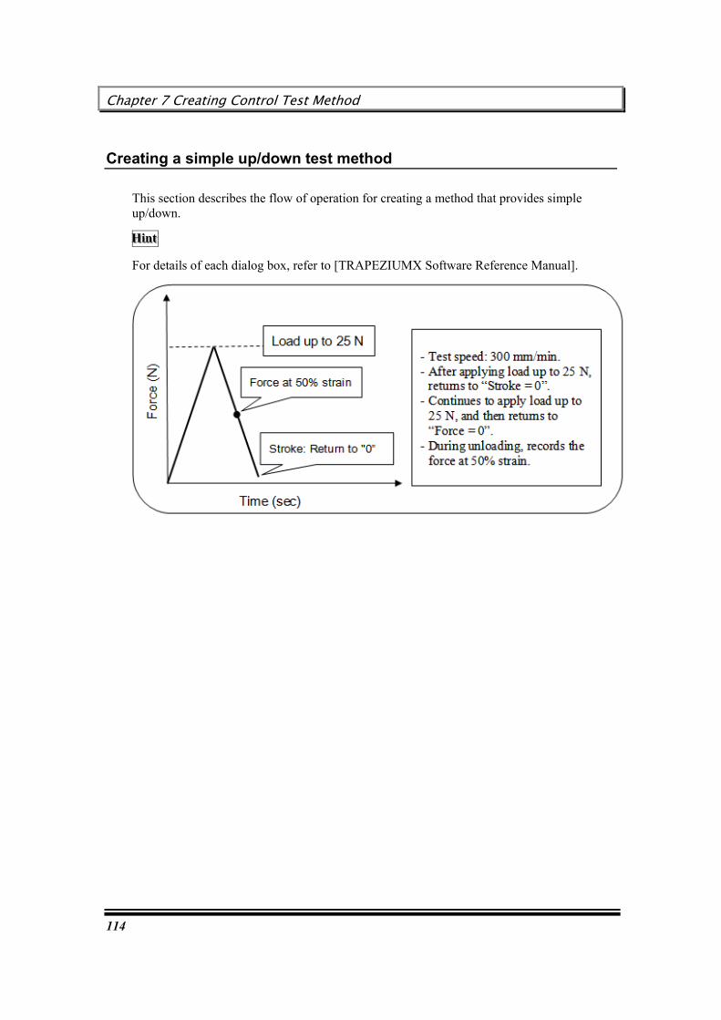
Creating a simple up/down test method
This section describes the flow of operation for creating a method that provides simple up/down.
HHHiiinnnttt
For details of each dialog box, refer to [TRAPEZIUMX Software Reference Manual].
User’s Guide
115
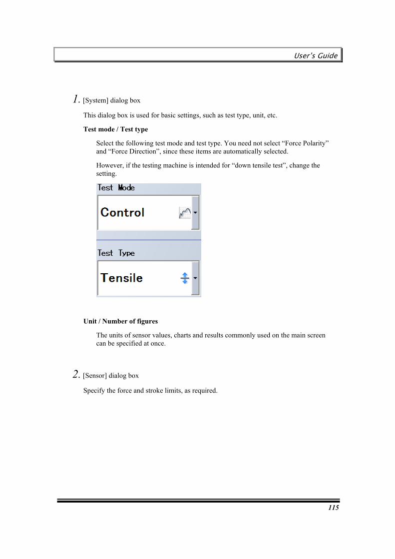
1. [System] dialog box
This dialog box is used for basic settings, such as test type, unit, etc.
Test mode / Test type
Select the following test mode and test type. You need not select “Force Polarity” and “Force Direction”, since these items are automatically selected.
However, if the testing machine is intended for “down tensile test”, change the setting.
Unit / Number of figures
The units of sensor values, charts and results commonly used on the main screen can be specified at once.
2. [Sensor] dialog box
Specify the force and stroke limits, as required.
Chapter 7 Creating Control Test Method
116
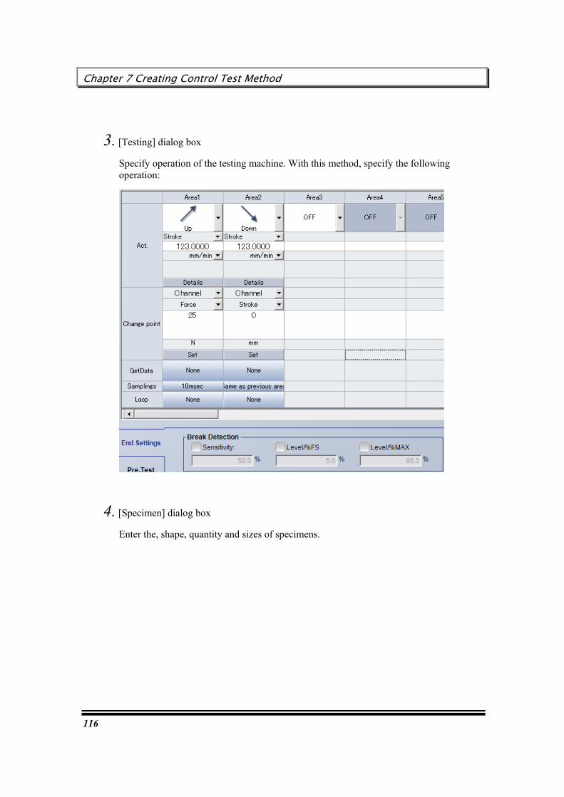
3. [Testing] dialog box
Specify operation of the testing machine. With this method, specify the following operation:
4. [Specimen] dialog box
Enter the, shape, quantity and sizes of specimens.

User’s Guide
117
5. [Data Processing Items] dialog box
Select required data processing items. With this method, select the following items:
Force at 50% strain during unloading
In this example, find a point at which “Stroke (strain)” reaches 50% in the second cycle during unloading.

Chapter 7 Creating Control Test Method
118
6. [Chart] / [Report] dialog box
Set up each dialog box, as required.

User’s Guide
119
Creating a stepped control test method
This section describes the flow of operation for creating a method that provides stepped motion by repeating move & hold cycles.
HHHiiinnnttt
For details of each dialog box, refer to [TRAPEZIUMX Software Reference Manual].

Chapter 7 Creating Control Test Method
120
1. [System] dialog box
This dialog box is used for basic settings, such as test type, unit, etc.
Test mode / Test type
Select the following test mode and test type. You need not select “Force Polarity” and “Force Direction”, since these items are automatically selected.
However, if the testing machine is intended for “down tensile test”, change the setting.
Unit / Number of figures
The units of sensor values, charts and results commonly used on the main screen can be specified at once.
2. [Sensor] dialog box
Specify the force and stroke limits, as required.

User’s Guide
121
3. [Testing] dialog box
Specify operation of the testing machine.

Chapter 7 Creating Control Test Method
122
5 mm down
(1) Click on the Area 1 loop setting field.
(2) Specify the following parameters in the loop setting dialog box, and click on [OK].
(3) Arrow marks are displayed in the Area 1 and Area 2 loop setting fields.
(4) Click on the Area 3 loop setting field. Perform the same setting procedure.
User’s Guide
123
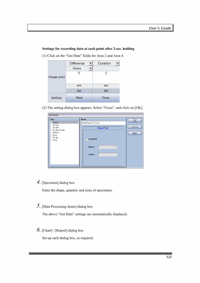
Settings for recording data at each point after 2-sec. holding
(1) Click on the “Get Data” fields for Area 2 and Area 4.
(2) The setting dialog box appears. Select “Force”, and click on [OK].
4. [Specimen] dialog box
Enter the shape, quantity and sizes of specimens.
5. [Data Processing Items] dialog box
The above “Get Data” settings are automatically displayed.
6. [Chart] / [Report] dialog box
Set up each dialog box, as required.

Chapter 7 Creating Control Test Method
124
This page is intentionally left blank.
User’s Guide
125
Chapter 8 Creating Texture Test Method
This chapter describes the procedure for creating a method of the tests that can be executed with the texture test software.
Creating a plunger compression test method
Creating a chewing test method
Chapter 8 Creating Texture Test Method
126
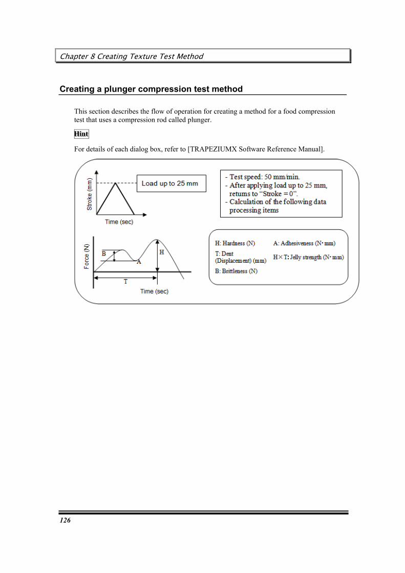
Creating a plunger compression test method
This section describes the flow of operation for creating a method for a food compression test that uses a compression rod called plunger.
HHHiiinnnttt
For details of each dialog box, refer to [TRAPEZIUMX Software Reference Manual].

User’s Guide
127
1. [System] dialog box
This dialog box is used for basic settings, such as test type, unit, etc.
Test mode / Test type
Select the following test mode and test type. You need not select “Force Polarity” and “Force Direction”, since these items are automatically selected.
However, if the testing machine is intended for “down tensile test”, change the setting.
Unit / Number of figures
The units of sensor values, charts and results commonly used on the main screen can be specified at once.
2. [Sensor] dialog box
Specify the force and stroke limits, as required.
Chapter 8 Creating Texture Test Method
128
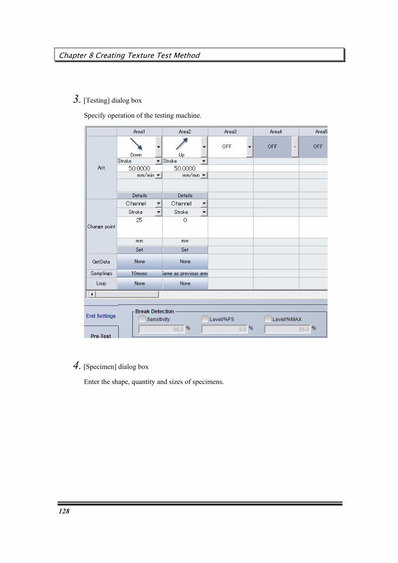
3. [Testing] dialog box
Specify operation of the testing machine.
4. [Specimen] dialog box
Enter the shape, quantity and sizes of specimens.
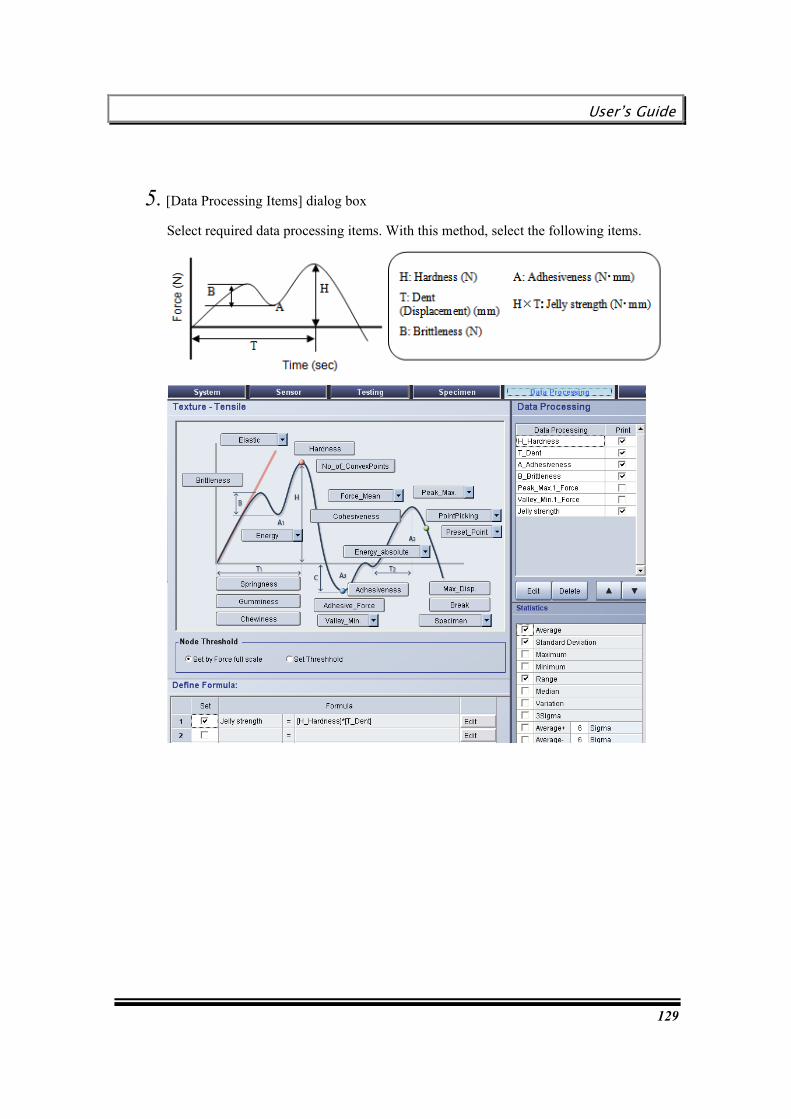
User’s Guide
129
5. [Data Processing Items] dialog box
Select required data processing items. With this method, select the following items.
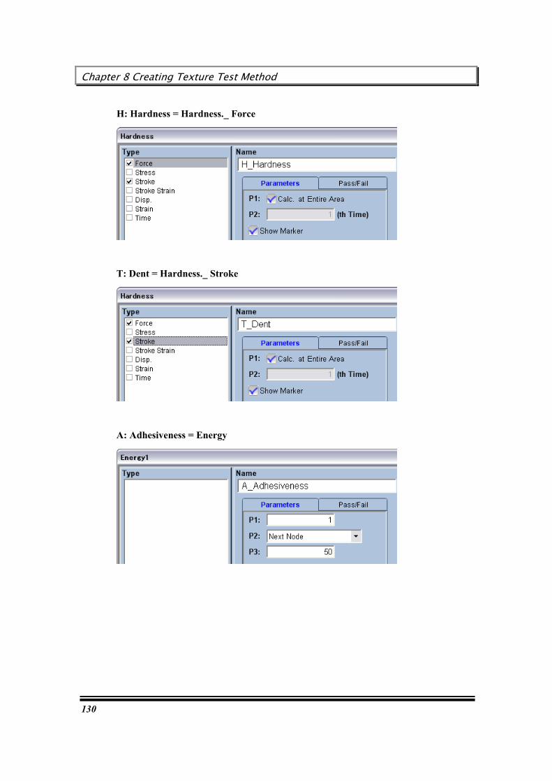
Chapter 8 Creating Texture Test Method
130
H: Hardness = Hardness._ Force
T: Dent = Hardness._ Stroke
A: Adhesiveness = Energy

User’s Guide
131
Jelly strength
Create a calculation formula as shown on the below.
B: Brittleness
Brittleness is caliculated with following expression.
Brittleness = [Peak_Max.1_Force] – [Vally_Min.1_Force]
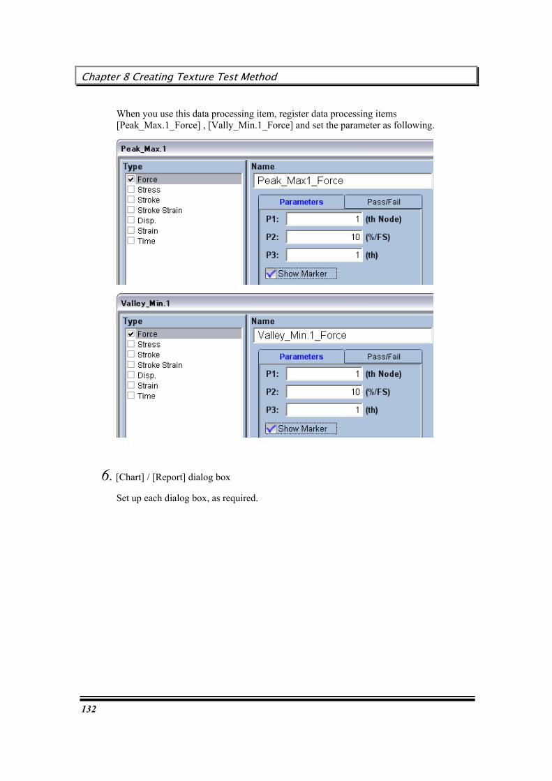
Chapter 8 Creating Texture Test Method
132
When you use this data processing item, register data processing items [Peak_Max.1_Force] , [Vally_Min.1_Force] and set the parameter as following.
6. [Chart] / [Report] dialog box
Set up each dialog box, as required.
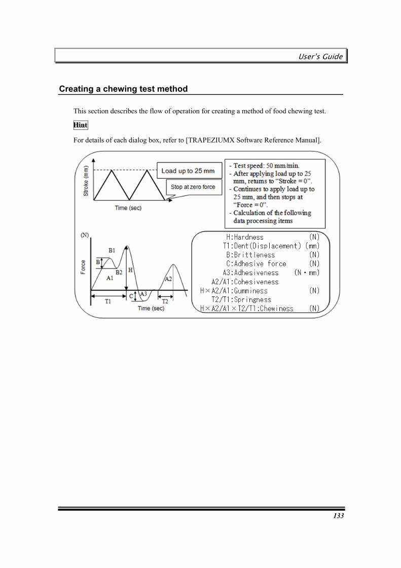
User’s Guide
133
Creating a chewing test method
This section describes the flow of operation for creating a method of food chewing test.
HHHiiinnnttt
For details of each dialog box, refer to [TRAPEZIUMX Software Reference Manual].
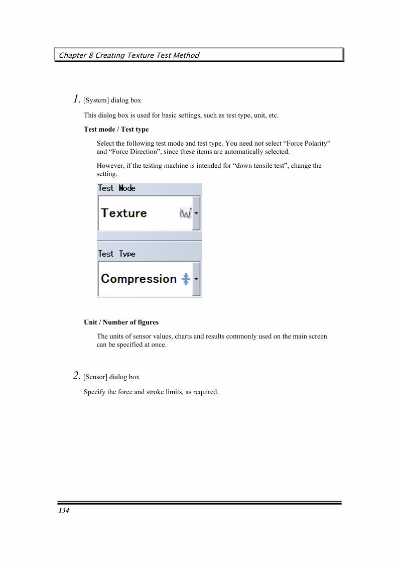
Chapter 8 Creating Texture Test Method
134
1. [System] dialog box
This dialog box is used for basic settings, such as test type, unit, etc.
Test mode / Test type
Select the following test mode and test type. You need not select “Force Polarity” and “Force Direction”, since these items are automatically selected.
However, if the testing machine is intended for “down tensile test”, change the setting.
Unit / Number of figures
The units of sensor values, charts and results commonly used on the main screen can be specified at once.
2. [Sensor] dialog box
Specify the force and stroke limits, as required.

User’s Guide
135
3. [Testing] dialog box
Specify operation of the testing machine.
4. [Specimen] dialog box
Enter the shape, quantity and sizes of specimens.
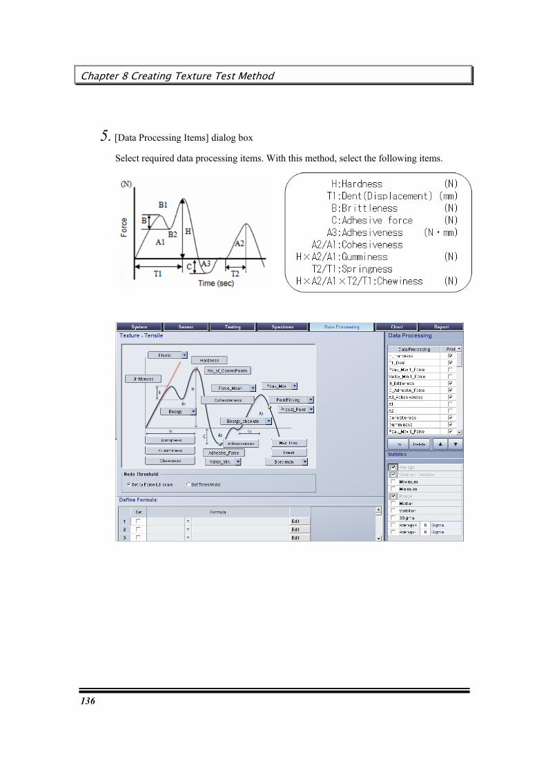
Chapter 8 Creating Texture Test Method
136
5. [Data Processing Items] dialog box
Select required data processing items. With this method, select the following items.

User’s Guide
137
H: Hardness = Hardness._ Force
T: Dent = Hardness._ Stroke
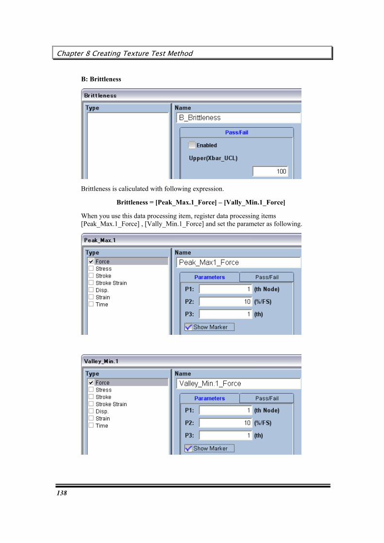
Chapter 8 Creating Texture Test Method
138
B: Brittleness
Brittleness is caliculated with following expression.
Brittleness = [Peak_Max.1_Force] – [Vally_Min.1_Force]
When you use this data processing item, register data processing items [Peak_Max.1_Force] , [Vally_Min.1_Force] and set the parameter as following.
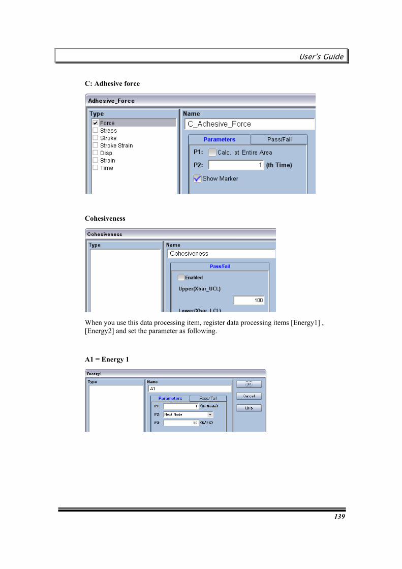
User’s Guide
139
C: Adhesive force
Cohesiveness
When you use this data processing item, register data processing items [Energy1] , [Energy2] and set the parameter as following.
A1 = Energy 1
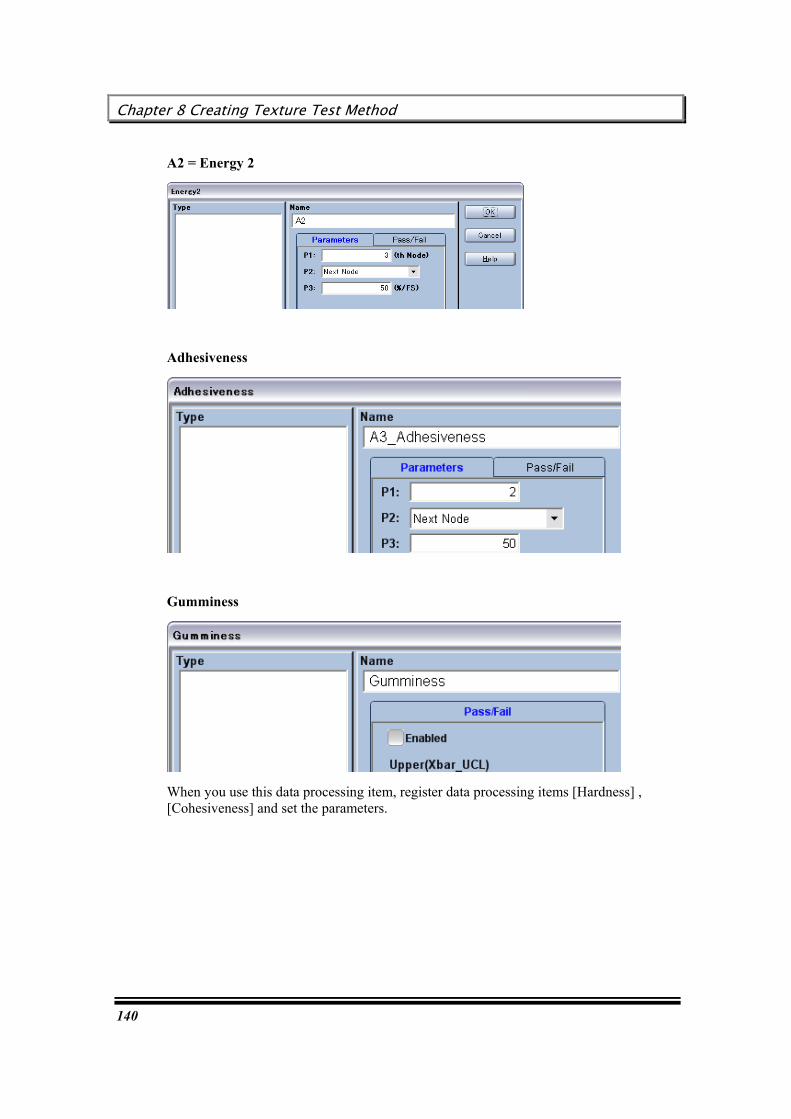
Chapter 8 Creating Texture Test Method
140
A2 = Energy 2
Adhesiveness
Gumminess
When you use this data processing item, register data processing items [Hardness] , [Cohesiveness] and set the parameters.

User’s Guide
141
Springness
When you use this data processing item, register data processing item [Peak_Max.2_Stroke] and set the parameters as following.
Chewiness
When you use this data processing item, register data processing item [Gumminess] , [Springness] and set the parameters.

Chapter 8 Creating Texture Test Method
142
HHHiiinnnttt
The node on the X axis can be set to an appropriate position in the chart window after completion of test.
RRReeelllaaattteeeddd kkkeeeyyywwwooorrrddd : “Texture mode data processing items”
6. [Chart] / [Report] dialog box
Set up each dialog box, as required.

User’s Guide
143
[Result Analysis and Output]
[Result Analysis and Output] describes the procedure for re-analyzing test results, and the procedure for printing and exporting test results to various media.
Chapter 9 Re-analyzing Test Result
144
Chapter 9 Re-analyzing Test Result
TRAPEZIUMX can re-analyze test results by changing data processing parameters after test execution, and also update a report and chart by changing the preset report and chart parameters.
Flow of re-analyzing operation
Analysis method selection guide
Opening a test file
Combining several test files
Batch change of various parameters (Re-analysis) – Method wizard
Direct change of analysis parameters on the main screen – Quick setting panel
Changing analysis parameters in the result window
Changing Pass/Fail judgment criteria in the result window
Changing printing order and print ON/OFF setting in the result window
Specifying a data processing point in a chart – Point picking
Changing an elastic line slope in a chart
Changing the peel test data processing range in a chart
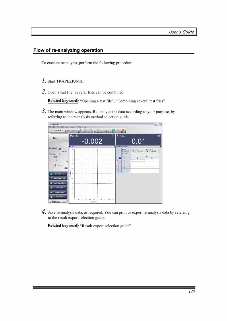
User’s Guide
145
Flow of re-analyzing operation
To execute reanalysis, perform the following procedure.
1. Start TRAPEZIUMX.
2. Open a test file. Several files can be combined.
RRReeelllaaattteeeddd kkkeeeyyywwwooorrrddd : “Opening a test file”, “Combining several test files”
3. The main window appears. Re-analyze the data according to your purpose, by referring to the reanalysis method selection guide.
4. Save re-analysis data, as required. You can print or export re-analysis data by referring to the result export selection guide.
RRReeelllaaattteeeddd kkkeeeyyywwwooorrrddd : “Result export selection guide”

Chapter 9 Re-analyzing Test Result
146
Opening a test file
1. Select [File] – [Open] – [Test]. The [Open Test] dialog box appears.
RRReeelllaaattteeeddd kkkeeeyyywwwooorrrddd : “[Open Test] dialog box”
2. Select a file, and click on [Open].
Combining several test files
After test results are saved in separate files, TRAPEZIUMX can combine the several test files into a single file.
Application of this function
You can compare the current measurement result with previous measurement results to check for any change.
If you save data in separate files, you can create a report afterward by selecting only required items.
Perform the following procedure
1. Select [File] – [Open] – [Test]. The [Open Test] dialog box appears.
RRReeelllaaattteeeddd kkkeeeyyywwwooorrrddd : “[Open Test] dialog box”
2. Mark the checkbox for all required items in the result list.
3. Click on [Open].

User’s Guide
147
Analysis method selection guide
TRAPEZIUMX provides various data analyses methods. Select a method suitable for your purpose from the following table.
Purpose Function Batch change of various parameters Re-analysis Direct change of analysis parameters on the main screen
Quick setting panel
Changing data processing analysis parameters
Changing analysis parameters in the result window
Changing only Pass/Fail judgment criteria
Changing Pass/Fail judgment criteria in the result window
Changing printing order and print ON/OFF setting
Changing printing order and print ON/OFF setting in the result window
Specifying a result point in a chart Point picking Changing an elastic line slope in a chart Changing an elastic line slope in a chart Changing the peel test data processing range
Changing the peel test data processing range in a chart
Changing specimen sizes Test wizard Changing report items Test wizard
Chapter 9 Re-analyzing Test Result
148
Batch change of various parameters (Re-analysis) – Method wizard
With TRAPEZIUMX, the operation for changing various parameters in the Method Wizard is called “Re-analysis”.
If you remember to execute reanalysis when changing preset parameters, you can perform general settings, even if you are not familiarized with other functions.
Perform the following procedure
1. Select [Test] – [Re-analysis], or click on [Re-analysis] on the toolbar.
2. According to the Method Wizard, edit required re-analysis parameters.
RRReeelllaaattteeeddd kkkeeeyyywwwooorrrddd : “Method wizard”
3. If you save the changed parameters in a method file, click on [Save].
4. The [Save a test method] dialog box appears. Save the parameters with a desired file name. The method file used for test execution is selected as the default setting. After parameter settings are completed, click on [Finish] on the navigation bar.
5. Save the re-analysis results.
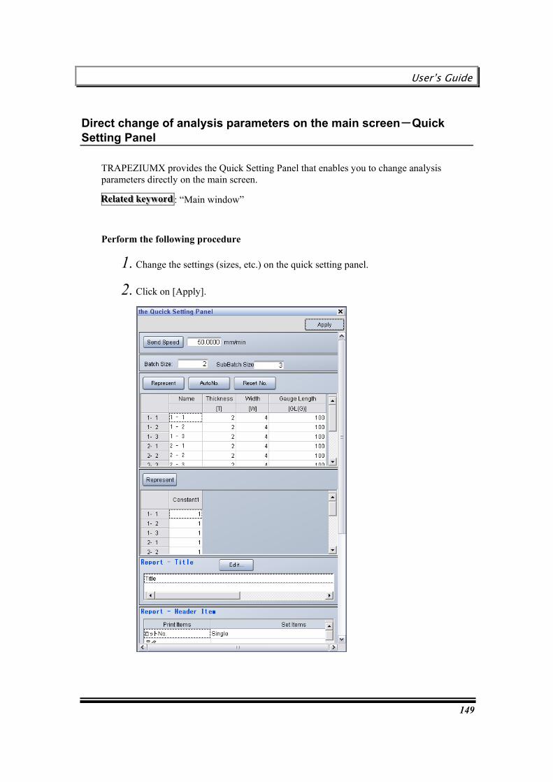
User’s Guide
149
Direct change of analysis parameters on the main screen-Quick Setting Panel
TRAPEZIUMX provides the Quick Setting Panel that enables you to change analysis parameters directly on the main screen.
RRReeelllaaattteeeddd kkkeeeyyywwwooorrrddd : “Main window”
Perform the following procedure
1. Change the settings (sizes, etc.) on the quick setting panel.
2. Click on [Apply].
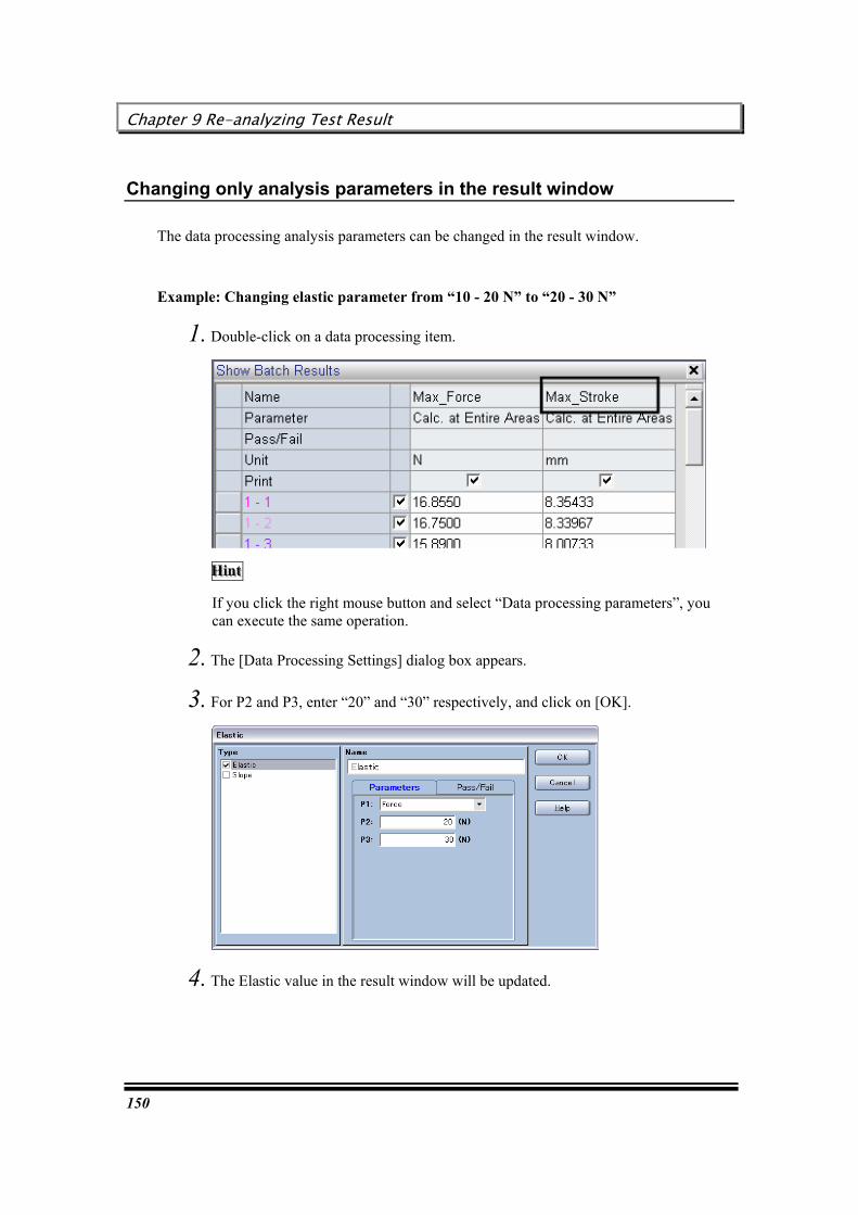
Chapter 9 Re-analyzing Test Result
150
Changing only analysis parameters in the result window
The data processing analysis parameters can be changed in the result window.
Example: Changing elastic parameter from “10 - 20 N” to “20 - 30 N”
1. Double-click on a data processing item.
HHHiiinnnttt
If you click the right mouse button and select “Data processing parameters”, you can execute the same operation.
2. The [Data Processing Settings] dialog box appears.
3. For P2 and P3, enter “20” and “30” respectively, and click on [OK].
4. The Elastic value in the result window will be updated.

User’s Guide
151
Changing Pass/Fail judgment criteria in the result window
Data processing Pass/Fail judgment criteria can be changed in the result window.
Example: Changing Max. Force judgment criteria to “50 – 70 N”
1. Double-click on a data processing item.
HHHiiinnnttt
If you click the right mouse button and select “Data processing parameters”, you can execute the same operation.
2. The [Data Processing Settings] dialog box appears.

Chapter 9 Re-analyzing Test Result
152
3. After selecting the [Pass/Fail] tab, enter “70” (upper limit) and “50” (lower limit), and click on [OK].
4. The Pass/Fail judgment criteria and the result in the result window will be updated.
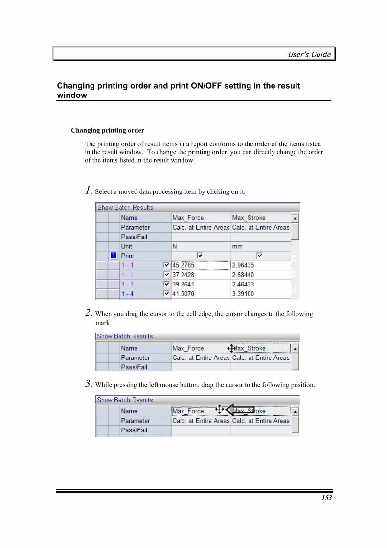
User’s Guide
153
Changing printing order and print ON/OFF setting in the result window
Changing printing order
The printing order of result items in a report conforms to the order of the items listed in the result window. To change the printing order, you can directly change the order of the items listed in the result window.
1. Select a moved data processing item by clicking on it.
2. When you drag the cursor to the cell edge, the cursor changes to the following mark.
3. While pressing the left mouse button, drag the cursor to the following position.
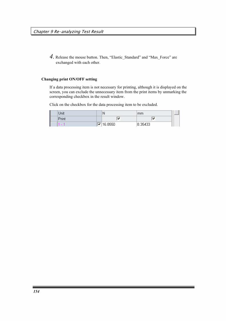
Chapter 9 Re-analyzing Test Result
154
4. Release the mouse button. Then, “Elastic_Standard” and “Max_Force” are exchanged with each other.
Changing print ON/OFF setting
If a data processing item is not necessary for printing, although it is displayed on the screen, you can exclude the unnecessary item from the print items by unmarking the corresponding checkbox in the result window.
Click on the checkbox for the data processing item to be excluded.
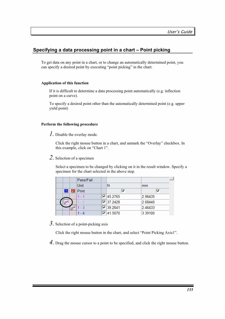
User’s Guide
155
Specifying a data processing point in a chart – Point picking
To get data on any point in a chart, or to change an automatically determined point, you can specify a desired point by executing “point picking” in the chart.
Application of this function
If it is difficult to determine a data processing point automatically (e.g. inflection point on a curve).
To specify a desired point other than the automatically determined point (e.g. upper yield point)
Perform the following procedure
1. Disable the overlay mode.
Click the right mouse button in a chart, and unmark the “Overlay” checkbox. In this example, click on “Chart 1”.
2. Selection of a specimen
Select a specimen to be changed by clicking on it in the result window. Specify a specimen for the chart selected in the above step.
3. Selection of a point-picking axis
Click the right mouse button in the chart, and select “Point Picking Axis1”.
4. Drag the mouse cursor to a point to be specified, and click the right mouse button.
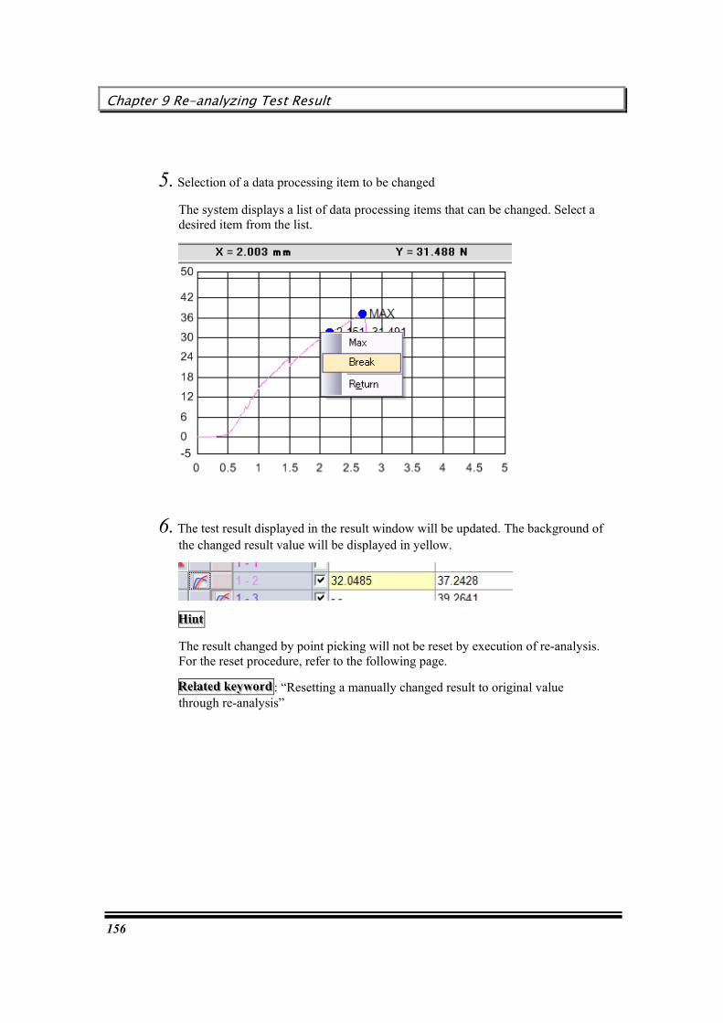
Chapter 9 Re-analyzing Test Result
156
5. Selection of a data processing item to be changed
The system displays a list of data processing items that can be changed. Select a desired item from the list.
6. The test result displayed in the result window will be updated. The background of the changed result value will be displayed in yellow.
HHHiiinnnttt
The result changed by point picking will not be reset by execution of re-analysis. For the reset procedure, refer to the following page.
RRReeelllaaattteeeddd kkkeeeyyywwwooorrrddd : “Resetting a manually changed result to original value through re-analysis”
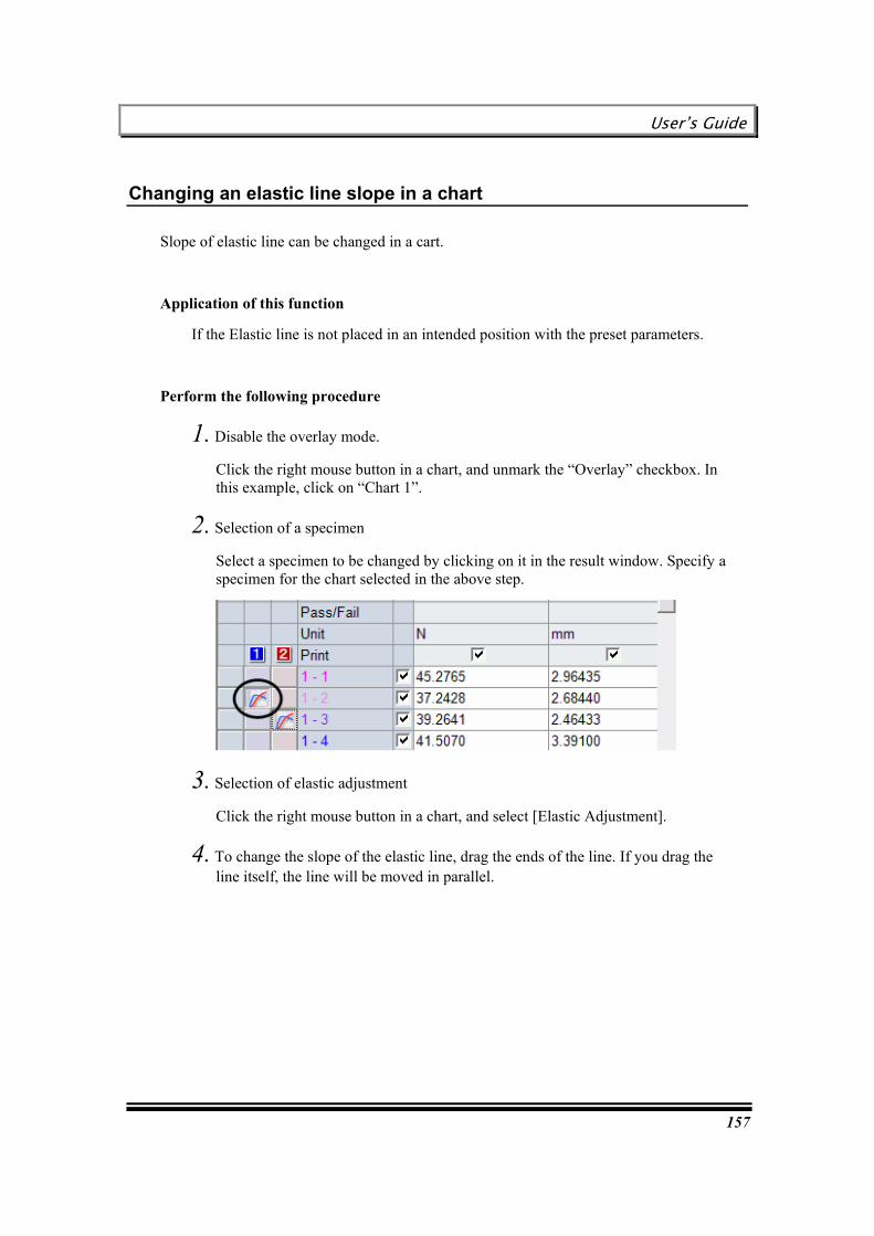
User’s Guide
157
Changing an elastic line slope in a chart
Slope of elastic line can be changed in a cart.
Application of this function
If the Elastic line is not placed in an intended position with the preset parameters.
Perform the following procedure
1. Disable the overlay mode.
Click the right mouse button in a chart, and unmark the “Overlay” checkbox. In this example, click on “Chart 1”.
2. Selection of a specimen
Select a specimen to be changed by clicking on it in the result window. Specify a specimen for the chart selected in the above step.
3. Selection of elastic adjustment
Click the right mouse button in a chart, and select [Elastic Adjustment].
4. To change the slope of the elastic line, drag the ends of the line. If you drag the line itself, the line will be moved in parallel.

Chapter 9 Re-analyzing Test Result
158
5. Registering the line position
Click the right mouse button again, and select [Elastic Adjustment].
This operation registers the elastic line position, and updates the value in the result window. Then, the system displays a list of data processing items that can be changed. Select a desired item from the list.
6. The test result displayed in the result window will be updated. The background of the changed result value will be displayed in yellow.
HHHiiinnnttt
The result changed with the above procedure will not be reset by execution of re-analysis. For the reset procedure, refer to the following page.
RRReeelllaaattteeeddd kkkeeeyyywwwooorrrddd : “Resetting a manually changed result to original value through re-analysis”

User’s Guide
159
Changing the peel test data processing range in a chart
For peel test, the data processing range for sampling peak and valley points can be changed with the mouse.
Perform the following procedure
1. Change the X axis to “Stroke”, and disable the overlay mode.
Click the right mouse button in a chart, and select “Property”. For the X axis, select “Stroke” in the chart property dialog box.
Furthermore, disable the overlay mode.
2. Selection of a specimen
Select a specimen to be changed by clicking on it in the result window. Specify a specimen for the chart selected in the above step.
3. Starting change of data processing range
Click the right mouse button in the chart, and select [Data Processing Area Adjustment].

Chapter 9 Re-analyzing Test Result
160
4. The vertical line that indicates the data processing range appears. Then, drag the line in parallel to an appropriate position.
5. Registering the line position
Click the right mouse button again, and select [Data Processing Area Adjustment]. This operation registers the data processing range, and updates the value in the result window.
HHHiiinnnttt
The data processing range changed with the above procedure will not be reset by execution of re-analysis. You must click the right mouse button on the chart again, and select “Reset Data Processing Area”.
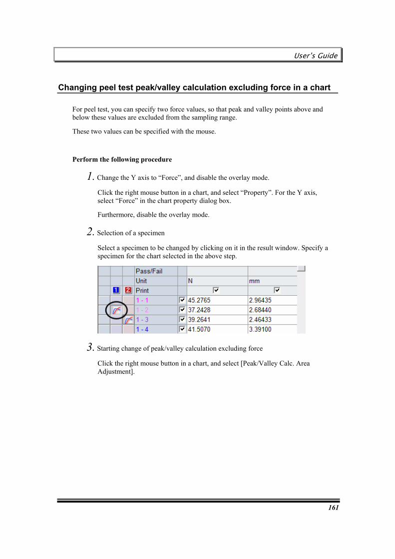
User’s Guide
161
Changing peel test peak/valley calculation excluding force in a chart
For peel test, you can specify two force values, so that peak and valley points above and below these values are excluded from the sampling range.
These two values can be specified with the mouse.
Perform the following procedure
1. Change the Y axis to “Force”, and disable the overlay mode.
Click the right mouse button in a chart, and select “Property”. For the Y axis, select “Force” in the chart property dialog box.
Furthermore, disable the overlay mode.
2. Selection of a specimen
Select a specimen to be changed by clicking on it in the result window. Specify a specimen for the chart selected in the above step.
3. Starting change of peak/valley calculation excluding force
Click the right mouse button in a chart, and select [Peak/Valley Calc. Area Adjustment].

Chapter 9 Re-analyzing Test Result
162
4. A horizontal line appears in the chart. Then, drag the line in parallel to an appropriate position.
5. Registering the line position
Click the right mouse button again, and select [Peak/Valley Calc. Area Adjustment]. Then, the value displayed in the result window will be updated.
HHHiiinnnttt
The sampling range changed with the above procedure will not be reset by execution of re-analysis. You must click the right mouse button on the chart again, and select “Reset Data Peak/Valley Calc. Area”.
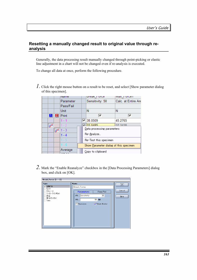
User’s Guide
163
Resetting a manually changed result to original value through re-analysis
Generally, the data processing result manually changed through point-picking or elastic line adjustment in a chart will not be changed even if re-analysis is executed.
To change all data at once, perform the following procedure.
1. Click the right mouse button on a result to be reset, and select [Show parameter dialog of this specimen].
2. Mark the “Enable Reanalyze” checkbox in the [Data Processing Parameters] dialog box, and click on [OK].

Chapter 9 Re-analyzing Test Result
164
This page is intentionally left blank.
User’s Guide
165
Chapter 10 Printing and Output of Test Result
This chapter describes the procedure for printing test results, and the procedure for exporting test results to various media after test execution.
Result export selection guide
Printing a report
Creating a report in a specified format with Excel (Excel report)
Sending E-mail
Automatically saving a test result in the CSV format in a network server (Network export)
TRAPEZIUMX WebPlus data export
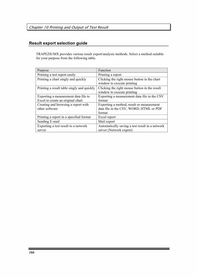
Chapter 10 Printing and Output of Test Result
166
Result export selection guide
TRAPEZIUMX provides various result export/analysis methods. Select a method suitable for your purpose from the following table.
Purpose Function Printing a test report easily Printing a report Printing a chart singly and quickly Clicking the right mouse button in the chart
window to execute printing Printing a result table singly and quickly Clicking the right mouse button in the result
window to execute printing Exporting a measurement data file to Excel to create an original chart
Exporting a measurement data file in the CSV format
Creating and browsing a report with other software
Exporting a method, result or measurement data file in the CSV, WORD, HTML or PDF format
Printing a report in a specified format Excel report Sending E-mail Mail export Exporting a test result to a network server
Automatically saving a test result in a network server (Network export)

User’s Guide
167
Printing a report
To print a report with TRAPEZIUMX, select [File] – [Print], or [File] – [Preview].
RRReeelllaaattteeeddd kkkeeeyyywwwooorrrddd : “Report Preview dialog box”
RRReeelllaaattteeeddd kkkeeeyyywwwooorrrddd : “Method wizard, Report dialog box”
Creating a report in a specified format with Excel (Excel report)
TRAPEZIUMX provides the Excel Report function, enabling a test result to be automatically inserted into a report prepared with Excel.
You can easily use the Excel Report function without learning new operations, because TRAPEZIUMX enables you to use the Excel function that must be separately purchased. This function is available only with a PC where Excel has been installed. For details of Excel operations, refer to the Excel operation manual.
Flow of Excel operations
When a template is not prepared:
Showing a result ® Crating a report (template), Preview, and Printing
When a template is prepared:
Showing a result ® Selection of a template ® Showing a report ® Edition, Preview and Printing

Chapter 10 Printing and Output of Test Result
168
Procedure for creating a template
This section describes the procedure for creating an Excel report template.
Once you create and save a template as described below, you need not create the template again for execution of the same test. The system calls the same template, and updates the result and chart data.
Perform the following procedure:
1. Execute a test, or open a test file to show a chart or result on the screen.
2. Select [File] – [Excel Report] – [New] from the menu.
3. Microsoft Excel automatically opens, and the following message appears. Then, select [Apply].
4. The following Excel file is displayed.
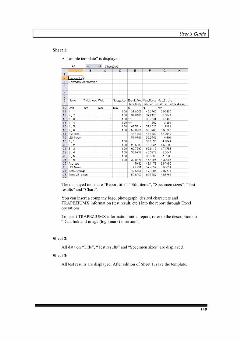
User’s Guide
169
Sheet 1:
A “sample template” is displayed.
The displayed items are “Report title”, “Edit items”, “Specimen sizes”, “Test results” and “Chart”.
You can insert a company logo, photograph, desired characters and TRAPEZIUMX information (test result, etc.) into the report through Excel operations.
To insert TRAPEZIUMX information into a report, refer to the description on “Data link and image (logo mark) insertion”.
Sheet 2:
All data on “Title”, “Test results” and “Specimen sizes” are displayed.
Sheet 3:
All test results are displayed. After edition of Sheet 1, save the template.

Chapter 10 Printing and Output of Test Result
170
HHHiiinnnttt
The document file name is the same as the TRAPEZIUMX test file name.
If the same document file name already exists, the file name is expressed as “(Test file name) + (Year/Month/Day_Hour_Minute).xls”.
Organization of Excel report
Excel report is organized as follows.
TRAPEZIUMX latest data will be automatically inserted into Sheet 2 and Sheet 3. Sheet 1 describes link to Sheet 2 and Sheet 3. A latest chart will be automatically pasted to Sheet 1. You can manually paste characters and images to Sheet 1. Sheet 1 can be printed as Excel report.
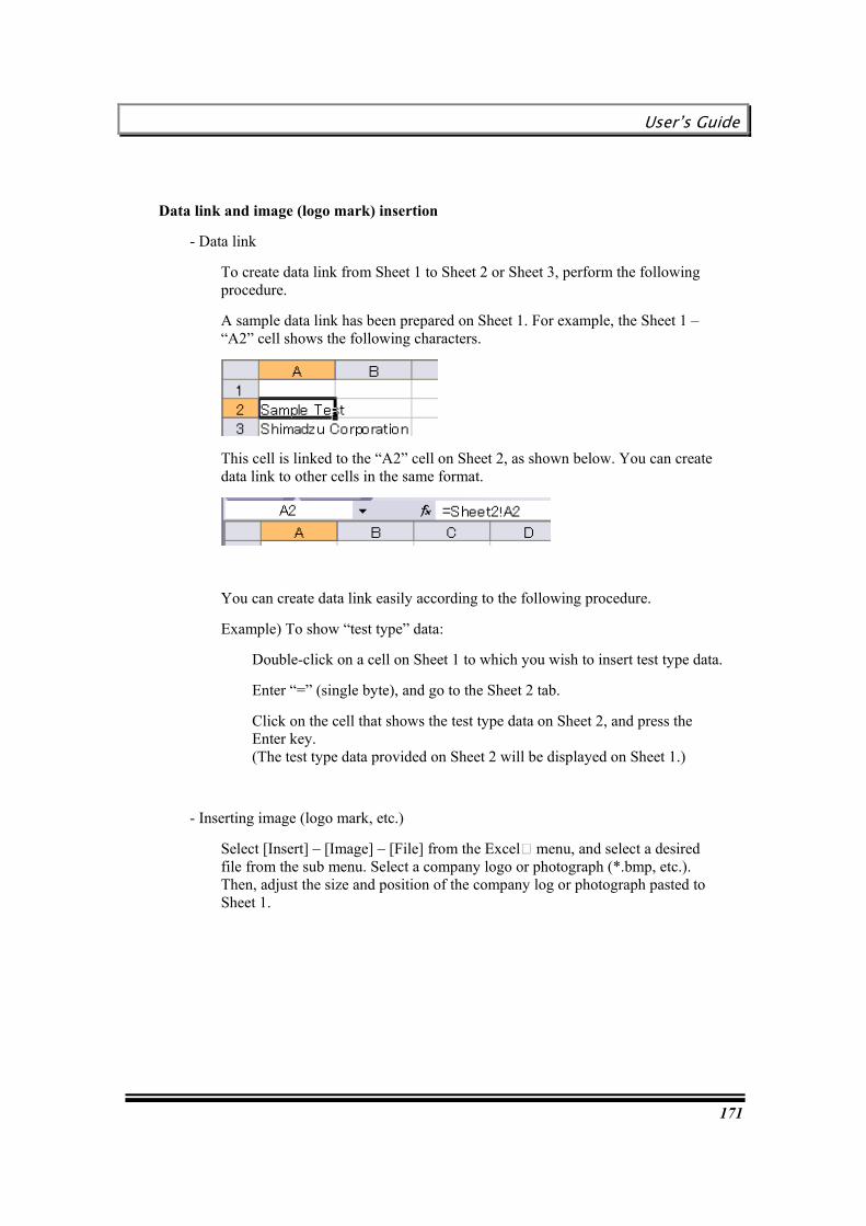
User’s Guide
171
Data link and image (logo mark) insertion
- Data link
To create data link from Sheet 1 to Sheet 2 or Sheet 3, perform the following procedure.
A sample data link has been prepared on Sheet 1. For example, the Sheet 1 – “A2” cell shows the following characters.
This cell is linked to the “A2” cell on Sheet 2, as shown below. You can create data link to other cells in the same format.
You can create data link easily according to the following procedure.
Example) To show “test type” data:
Double-click on a cell on Sheet 1 to which you wish to insert test type data.
Enter “=” (single byte), and go to the Sheet 2 tab.
Click on the cell that shows the test type data on Sheet 2, and press the Enter key. (The test type data provided on Sheet 2 will be displayed on Sheet 1.)
- Inserting image (logo mark, etc.)
Select [Insert] – [Image] – [File] from the Excel menu, and select a desired file from the sub menu. Select a company logo or photograph (*.bmp, etc.). Then, adjust the size and position of the company log or photograph pasted to Sheet 1.
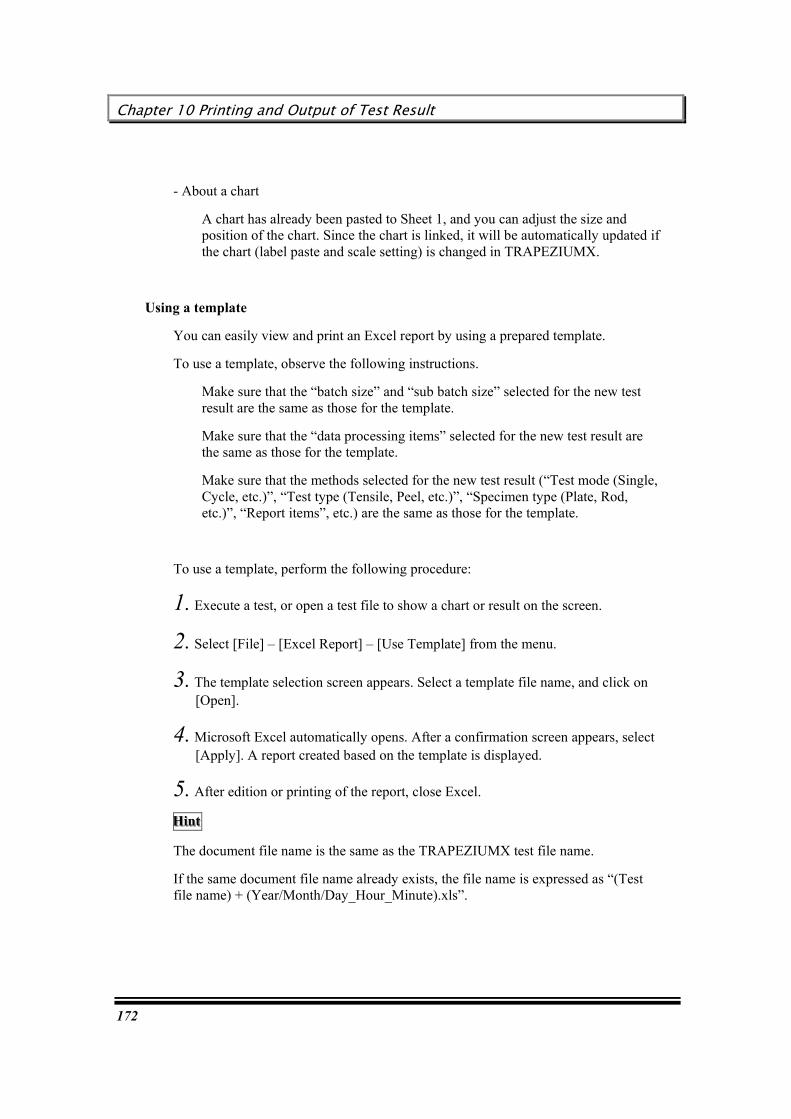
Chapter 10 Printing and Output of Test Result
172
- About a chart
A chart has already been pasted to Sheet 1, and you can adjust the size and position of the chart. Since the chart is linked, it will be automatically updated if the chart (label paste and scale setting) is changed in TRAPEZIUMX.
Using a template
You can easily view and print an Excel report by using a prepared template.
To use a template, observe the following instructions.
Make sure that the “batch size” and “sub batch size” selected for the new test result are the same as those for the template.
Make sure that the “data processing items” selected for the new test result are the same as those for the template.
Make sure that the methods selected for the new test result (“Test mode (Single, Cycle, etc.)”, “Test type (Tensile, Peel, etc.)”, “Specimen type (Plate, Rod, etc.)”, “Report items”, etc.) are the same as those for the template.
To use a template, perform the following procedure:
1. Execute a test, or open a test file to show a chart or result on the screen.
2. Select [File] – [Excel Report] – [Use Template] from the menu.
3. The template selection screen appears. Select a template file name, and click on [Open].
4. Microsoft Excel automatically opens. After a confirmation screen appears, select [Apply]. A report created based on the template is displayed.
5. After edition or printing of the report, close Excel.
HHHiiinnnttt
The document file name is the same as the TRAPEZIUMX test file name.
If the same document file name already exists, the file name is expressed as “(Test file name) + (Year/Month/Day_Hour_Minute).xls”.

User’s Guide
173
Sending E-mail
TRAPEZIUMX can send a report or operation history via E-mail. E-mail can be sent to registered users or Shimadzu technical support office.
Perform the following procedure
1. E-mail export settings
Select [Tools] – [Mail and Network export Settings], and set up the [Network Export Settings] dialog box.
RRReeelllaaattteeeddd kkkeeeyyywwwooorrrddd : “[Network Export Settings] dialog box – [Mail Export] tab”
2. Automatic export
When the automatic export setting is enabled, TRAPEZIUMX automatically sends E-mail at a specified timing.
3. Manual export
To send E-mail at an arbitrary timing, select [File] – [Send Email]. Select the export contents and address, and click on [OK].
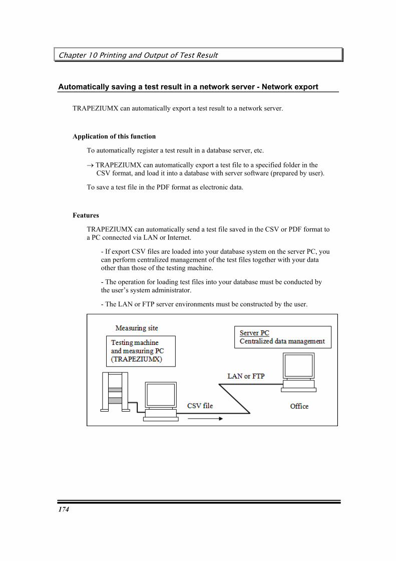
Chapter 10 Printing and Output of Test Result
174
Automatically saving a test result in a network server - Network export
TRAPEZIUMX can automatically export a test result to a network server.
Application of this function
To automatically register a test result in a database server, etc.
® TRAPEZIUMX can automatically export a test file to a specified folder in the CSV format, and load it into a database with server software (prepared by user).
To save a test file in the PDF format as electronic data.
Features
TRAPEZIUMX can automatically send a test file saved in the CSV or PDF format to a PC connected via LAN or Internet.
- If export CSV files are loaded into your database system on the server PC, you can perform centralized management of the test files together with your data other than those of the testing machine.
- The operation for loading test files into your database must be conducted by the user’s system administrator.
- The LAN or FTP server environments must be constructed by the user.
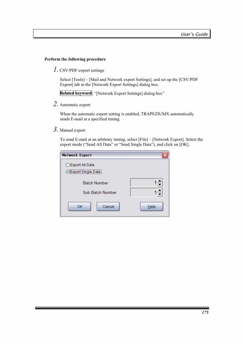
User’s Guide
175
Perform the following procedure
1. CSV/PDF export settings
Select [Tools] – [Mail and Network export Settings], and set up the [CSV/PDF Export] tab in the [Network Export Settings] dialog box.
RRReeelllaaattteeeddd kkkeeeyyywwwooorrrddd : “[Network Export Settings] dialog box”
2. Automatic export
When the automatic export setting is enabled, TRAPEZIUMX automatically sends E-mail at a specified timing.
3. Manual export
To send E-mail at an arbitrary timing, select [File] – [Network Export]. Select the export mode (“Send All Data” or “Send Single Data”), and click on [OK].

Chapter 10 Printing and Output of Test Result
176
This page is intentionally left blank.

User’s Guide
177
[Settings]
[Settings] describes user management, screen and other settings for this software, and the testing machine hardware settings.
Chapter 11 User Management Settings
178
Chapter 11 User Management Settings
This chapter describes the TRAPEZIUMX user settings.
User management
Types of users registered with initial settings
Original authority groups
Creating a new authority group
Adding a user
Changing user information
Deleting a user
Skipping login name/password entry at startup

User’s Guide
179
User management
TRAPEZIUMX can limit functions available by user.
TRAPEZIUMX provides user categories, such as “Administrator”, or administering user authorized for all functions (changing a method etc.), and “User” or general users authorized for test execution functions only (not authorized to change a method).
Limitation on available functions can prevent a preset method from being accidentally changed, or prevent measured results from being falsified, thus ensuring security improvement.
Groups
Management of users’ authorities is based on a concept of “Groups”, or a pack of several functions.
Every user must belong to any of the Groups.
With the initial settings, TRAPEZIUMX provides three Groups. For details, refer to “Types of users registered with initial settings”.
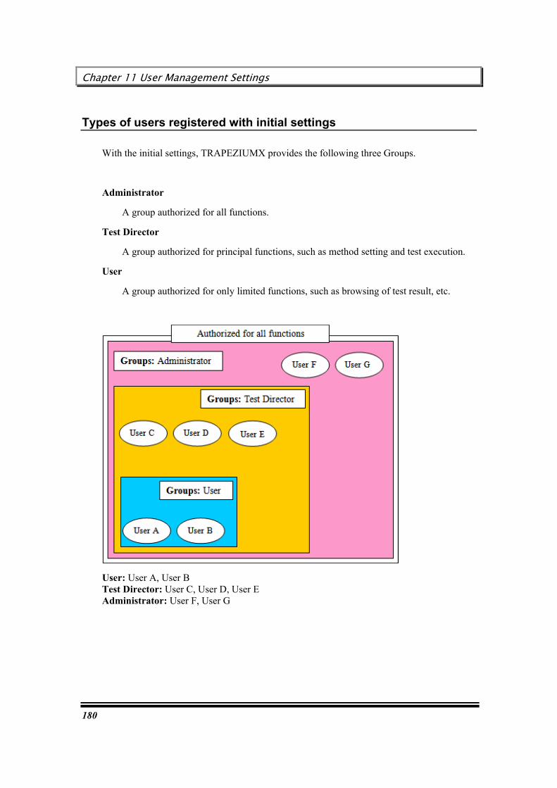
Chapter 11 User Management Settings
180
Types of users registered with initial settings
With the initial settings, TRAPEZIUMX provides the following three Groups.
Administrator
A group authorized for all functions.
Test Director
A group authorized for principal functions, such as method setting and test execution.
User
A group authorized for only limited functions, such as browsing of test result, etc.
User: User A, User B Test Director: User C, User D, User E Administrator: User F, User G

User’s Guide
181
Types of users and authorized functions registered with initial settings are listed below. Menu items that are not included in the following table are available for all users.
Groups
TRAPEZIUMX menu item Administrator
Test Director User
[Method] ○ × × [Method] ○ ○ ○ [Execute tasks] ○ ○ ○
[New]
[SPC/SQC] ○ × × [Method] ○ × × [Test] ○ ○ ○
[Open]
[SPC/SQC] ○ ○ × [Save] ○ ○ ○
[Method] ○ × × [Test] ○ ○ ○
[Save As]
[SPC/SQC] ○ × × [Export File] ○ ○ ○ [Network Export] ○ ○ ○ [Mail Export] ○ ○ ○ [Export for WebPlus] ○ ○ ○ [Print] ○ ○ ○ [Preview] ○ ○ ○ [Print Chart] ○ ○ ○ [Print Result] ○ ○ ○
[New] ○ ○ ○ [Excel Report] [Use Template] ○ ○ ○
[Recent Methods] ○ × × [Recent Tests] ○ ○ ○
[File]
[Recent SPC/SQC Data] ○ ○ × [Cut] ○ ○ × [Edit] [Insert] ○ ○ × [Re-Analyze] ○ ○ × [Test] [Re-Test] ○ ○ ×
[Display] tab ○ ○ ○ [Navigation] tab ○ ○ ○ [Start Up / Auto Save] tab ○ ○ ○
[Options]
[Log / Backup] tab ○ × × [Schedule Settings] ○ ○ × [Mail and Network Export Settings]
○ × ×
[User Accounts] ○ × × [Event Log] ○ ○ ×
[Tools]
[Change Password] ○ ○ ○

Chapter 11 User Management Settings
182
[Hardware Settings] ○ × × [Selfcheck] ○ × ×
Hardware
[Registration of Testing machines and jigs]
○ × ×

User’s Guide
183
Original Groups
In addition to the Groups registered with initial settings, you can create up to five original Groups.
For the Groups creating procedure, refer to “Creating new Groups”. For the new user creating procedure, refer to “Adding a user”.
The following is a conceptual diagram for creation of new Groups.
User: User A, User B Test Director: User C, User D, User E Administrator: User F, User G Optional group: User H

Chapter 11 User Management Settings
184
Creating new Groups
In addition to the Groups registered with initial settings, you can create up to five user groups that can be customized.
You can assign a desired name to the new user group.
You can create new Groups according to the following procedure.
1. Start TRAPEZIUMX.
2. Click on [User Accounts].
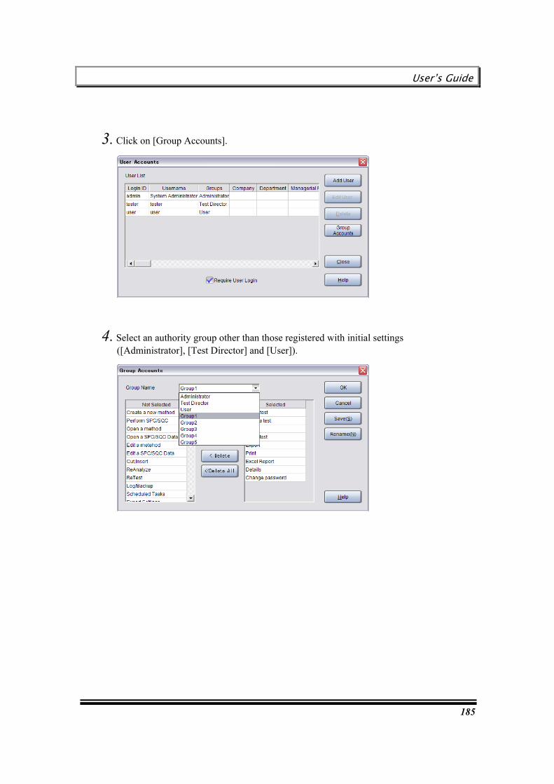
User’s Guide
185
3. Click on [Group Accounts].
4. Select an authority group other than those registered with initial settings ([Administrator], [Test Director] and [User]).

Chapter 11 User Management Settings
186
5. Click on [Add All], or select an authority to be added from the [Not Selected] list on the left of the screen, and click on [Add].
6. If you intend to delete any authority, select the authority to be deleted from the [Selected] list on the right of the screen, and click on [Delete].
7. To quit the setting procedure, click on [OK], and close the window. If you continue to set up different Groups, click on [Save], and return to the above Step 4.

User’s Guide
187
The TRAPEZIUMX menu items corresponding to individual authorities are listed below.
Authority TRAPEZIUMX menu
[Create a new method] [Method] [Method] [Run a test] [Execute tasks]
[Perform SPC/SQC]
[New]
[SPC/SQC] [Open a method] [Method] [Open a test] [Test] [Open SPC/SQC Data]
[Open]
[SPC/SQC] [Save] [Save] [Edit a method] [Method] [Edit a test] [Test] [Edit SPC/SQC Data]
[Save As]
[SPC/SQC] [Export File] [Network Export] [Mail Export]
[Export]
[Export for WebPlus] [Print] [Preview] [Print Chart]
[Print]
[Print Result] [New] [Excel Report] [Excel Report] [Use Template]
[Open a method] [Recent Methods] [Open a test] [Recent Tests] [Open SPC/SQC Data]
[File]
[Recent SPC/SQC Data] [Cut] [Cut], [Insert] [Edit] [Insert]
[Re-Analyze] [Re-Analyze] [Re-Test]
[Test] [Re-Test]
[Display] tab [Navigation] tab
[Details]
[Start Up / Auto Save] tab [Log/Backup]
[Options]
[Log / Backup] tab [Scheduled Tasks] [Schedule Settings] [Export Settings] [Mail and Network
Export Settings]
[User Accounts] [User Accounts] [Event Log] [Event Log] [Change password]
[Tools]
[Change Password] [Hardware Settings] [Hardware Settings] [Selfcheck] [Selfcheck] [Registration of Testing machines and jigs]
[Hardware]
[Registration of Testing machines and jigs]

Chapter 11 User Management Settings
188
Adding a user
You can create a new user according to the following procedure.
1. Start TRAPEZIUMX.
2. Click on [User Accounts].
3. Click on [Add User].

User’s Guide
189
4. Enter each setting item.
5. Specify an authority group in the Groups field, and click on [OK].

Chapter 11 User Management Settings
190
Changing user information
You can change user information according to the following procedure.
1. Start TRAPEZIUMX.
2. Click on [User Accounts].
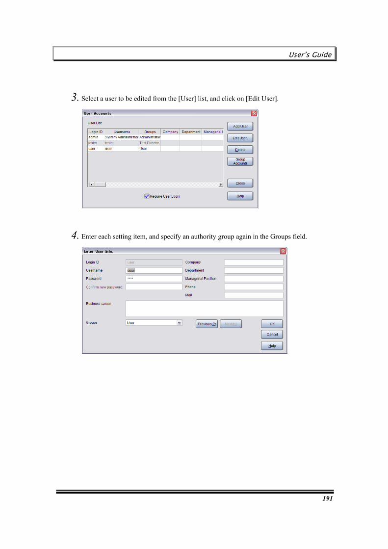
User’s Guide
191
3. Select a user to be edited from the [User] list, and click on [Edit User].
4. Enter each setting item, and specify an authority group again in the Groups field.
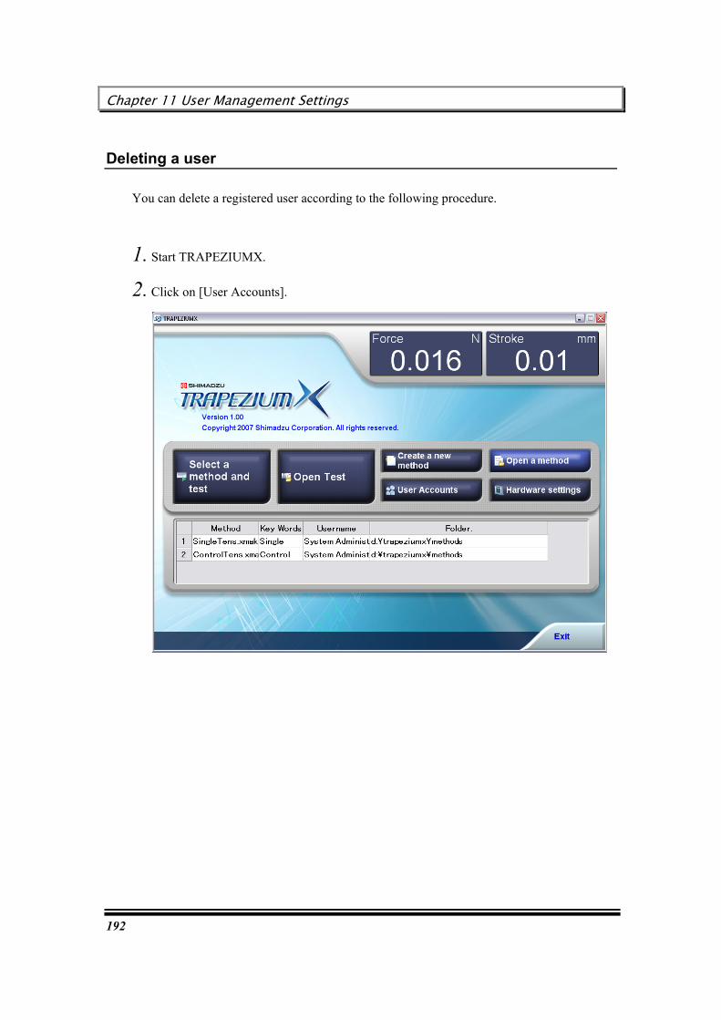
Chapter 11 User Management Settings
192
Deleting a user
You can delete a registered user according to the following procedure.
1. Start TRAPEZIUMX.
2. Click on [User Accounts].
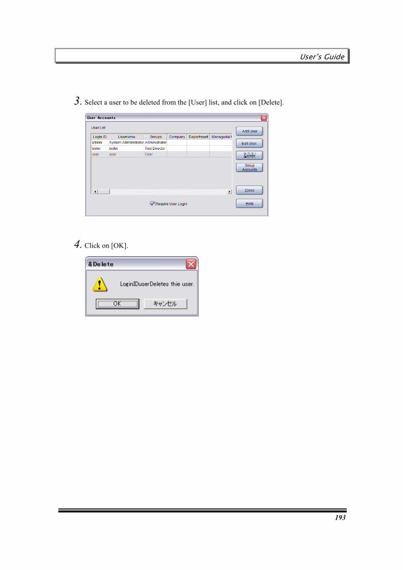
User’s Guide
193
3. Select a user to be deleted from the [User] list, and click on [Delete].
4. Click on [OK].
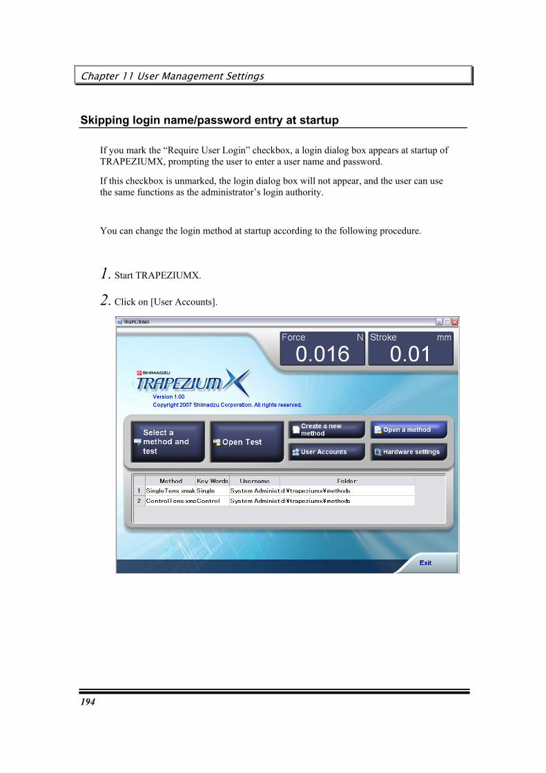
Chapter 11 User Management Settings
194
Skipping login name/password entry at startup
If you mark the “Require User Login” checkbox, a login dialog box appears at startup of TRAPEZIUMX, prompting the user to enter a user name and password.
If this checkbox is unmarked, the login dialog box will not appear, and the user can use the same functions as the administrator’s login authority.
You can change the login method at startup according to the following procedure.
1. Start TRAPEZIUMX.
2. Click on [User Accounts].

User’s Guide
195
3. Operate the “Require User Login” checkbox at the bottom of the screen.
4. Click on [Close].
5. If you mark the above checkbox in the above Step 3, the login dialog box appears at the next startup.

Chapter 11 User Management Settings
196
This page is intentionally left blank.

User’s Guide
197
Chapter 12 Customizing Main Screen
This chapter describes the procedure for customizing the window layout and operation buttons displayed on the TRAPEZIUMX main screen for user’s convenience.
Customizing the toolbar
Changing the toolbar size
Changing the senor display ON/OFF status
Changing the chart/result window display ON/OFF status
Changing the chart/result window size
Changing the chart/result window layout
Setting up the Quick Setting Panel
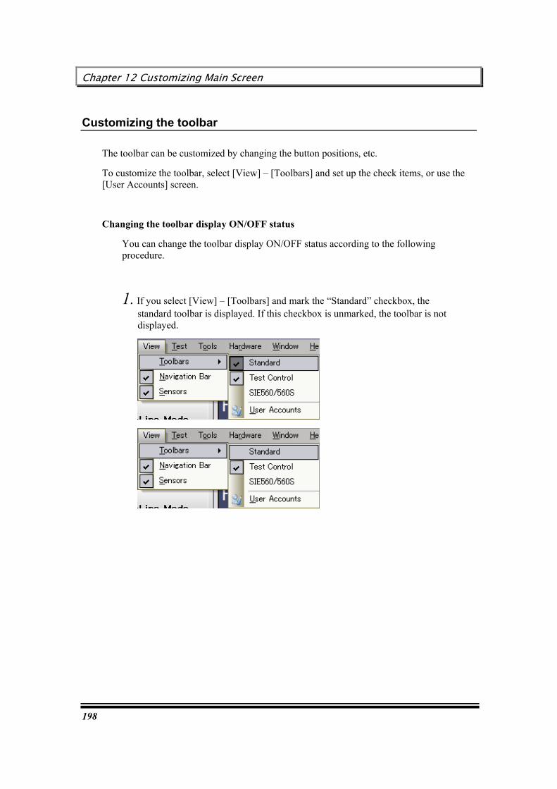
Chapter 12 Customizing Main Screen
198
Customizing the toolbar
The toolbar can be customized by changing the button positions, etc.
To customize the toolbar, select [View] – [Toolbars] and set up the check items, or use the [User Accounts] screen.
Changing the toolbar display ON/OFF status
You can change the toolbar display ON/OFF status according to the following procedure.
1. If you select [View] – [Toolbars] and mark the “Standard” checkbox, the standard toolbar is displayed. If this checkbox is unmarked, the toolbar is not displayed.

User’s Guide
199
2. If you select [View] – [Toolbars] and mark the “Test Control” checkbox, the toolbar intended for test control is displayed. If this checkbox is unmarked, the test control toolbar is not displayed.
Customizing the toolbar
Generally, the toolbar customize settings are classified into the following three types.
- Toolbar
Used for button appearance and text position settings.
- Command
Used for addition or deletion of the buttons displayed on the toolbar.
- Options
Used for color, font and image smoothing settings.

Chapter 12 Customizing Main Screen
200
You can customize the toolbar according to the following procedure.
1. Select [View] – [Toolbars], and click on [User Accounts].
2. You can freely edit the settings in the [Customize toolbars] dialog box.
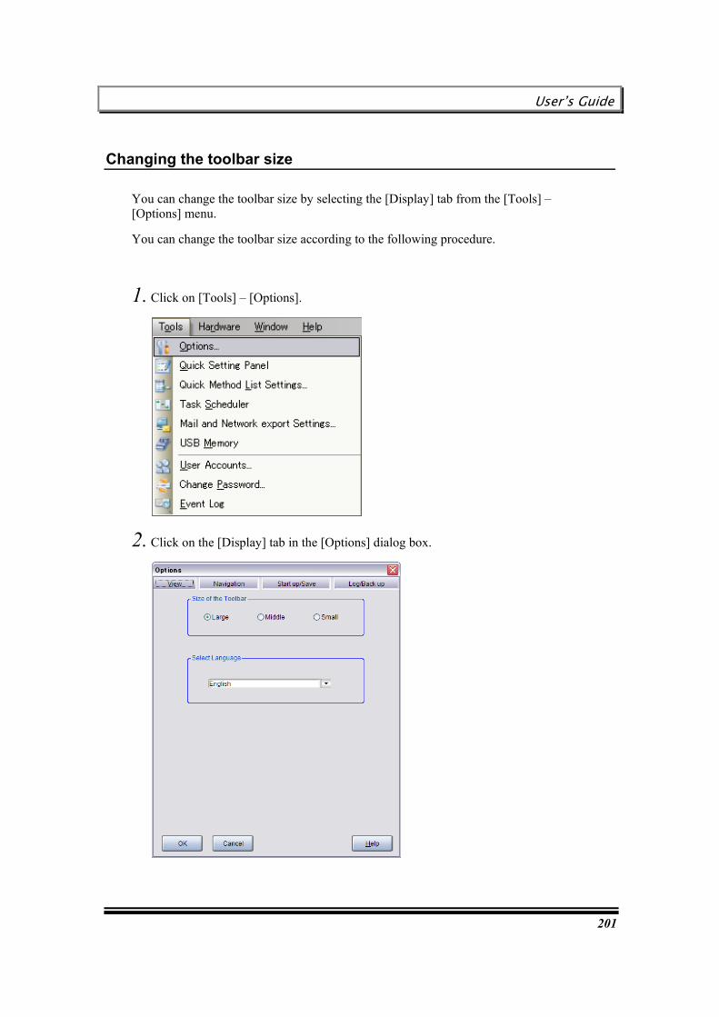
User’s Guide
201
Changing the toolbar size
You can change the toolbar size by selecting the [Display] tab from the [Tools] – [Options] menu.
You can change the toolbar size according to the following procedure.
1. Click on [Tools] – [Options].
2. Click on the [Display] tab in the [Options] dialog box.

Chapter 12 Customizing Main Screen
202
3. Select “Large”, “Middle” or “Sm” for Size.
4. Click on [OK], and close the dialog box.

User’s Guide
203
Changing the senor display ON/OFF status
You can specify whether to show or hide sensors by operating the checkbox in the [View] – [Sensors] menu.
To show sensor:
To hide sensor:
Changing the chart/result window display ON/OFF status
You can specify whether to show or hide each window on the result screen by operating the checkbox for each window.

Chapter 12 Customizing Main Screen
204
Changing the chart/result window size
You can freely change the size of each window on the result screen.
You can change the window size according to the following procedure.
1. Align the mouse cursor with the window frame. (Refer to the marking in the figure below.)
2. When the mouse cursor changes to the following shape, drag the cursor to slide the window frame.
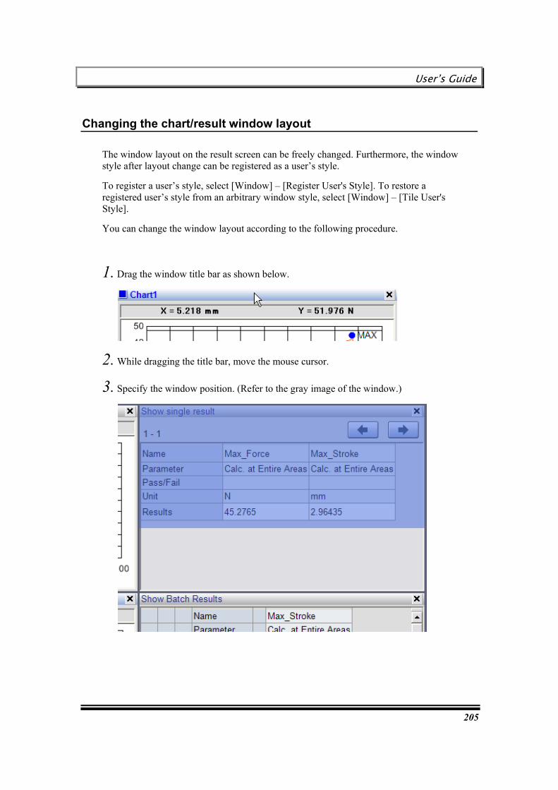
User’s Guide
205
Changing the chart/result window layout
The window layout on the result screen can be freely changed. Furthermore, the window style after layout change can be registered as a user’s style.
To register a user’s style, select [Window] – [Register User's Style]. To restore a registered user’s style from an arbitrary window style, select [Window] – [Tile User's Style].
You can change the window layout according to the following procedure.
1. Drag the window title bar as shown below.
2. While dragging the title bar, move the mouse cursor.
3. Specify the window position. (Refer to the gray image of the window.)
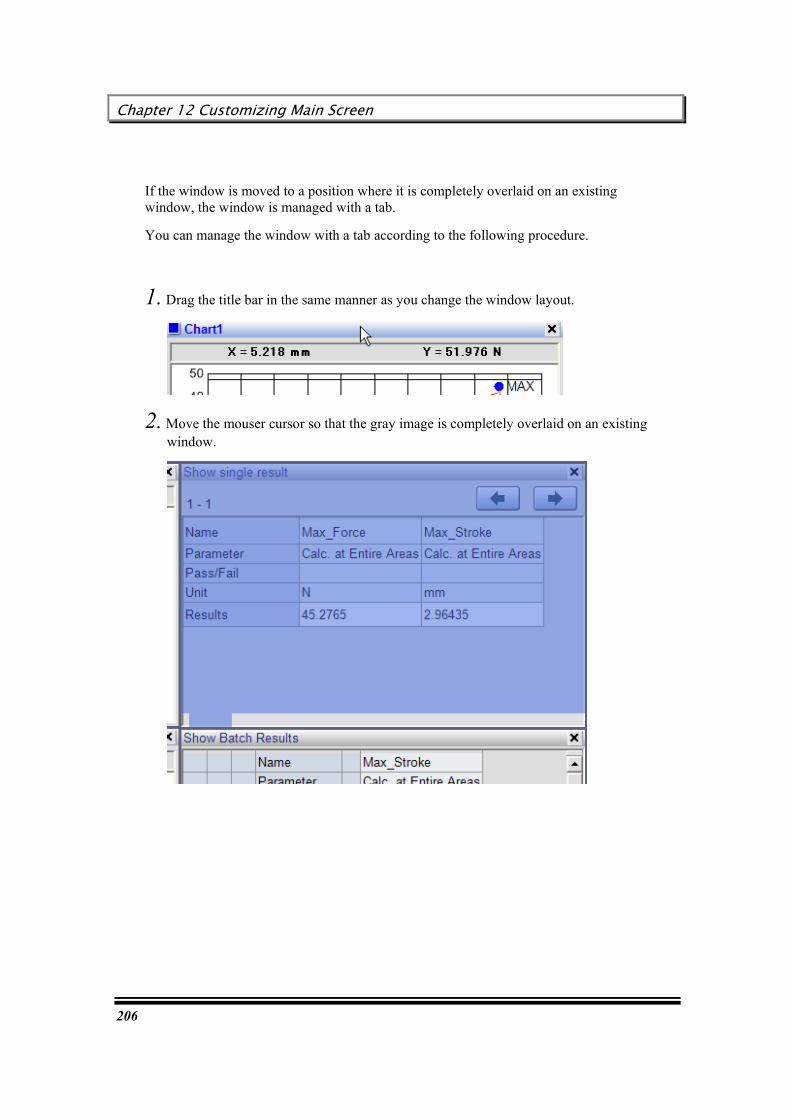
Chapter 12 Customizing Main Screen
206
If the window is moved to a position where it is completely overlaid on an existing window, the window is managed with a tab.
You can manage the window with a tab according to the following procedure.
1. Drag the title bar in the same manner as you change the window layout.
2. Move the mouser cursor so that the gray image is completely overlaid on an existing window.

User’s Guide
207
3. If a window can be managed with a tab, the bottom left part of the gray image changes to a tab mark, as shown below. Confirm this status to determine the window layout.
4. When the window is managed with a tab, the title bar is displayed on the tab, as shown below.
To restore the normal window style, select [Window] – [Tile Vertically] or [Tile Horizontally].

Chapter 12 Customizing Main Screen
208
Setting up the Quick Setting Panel
This function is used to change preset values of a method during test execution. The items to be displayed on the panel should be specified in advance.
Selectable items are as follows.

User’s Guide
209
Chapter 13 Various Settings of TRAPEZIUMX
This chapter describes various setting procedures for TRAPEZIUMX.
Selecting a display language
Changing the startup screen
Using the Auto Save function
Using the Backup function
Setting up software and testing machine operation logs
Setting up a test schedule
Registering a frequently used method (Quick Method List)
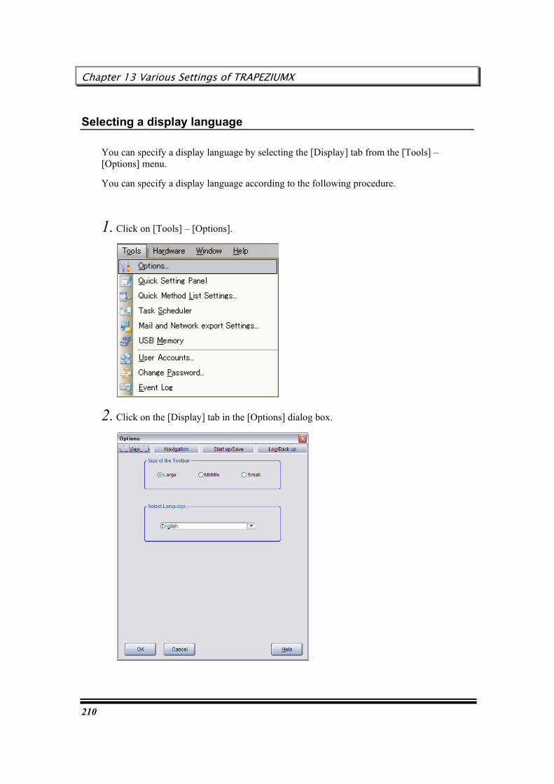
Chapter 13 Various Settings of TRAPEZIUMX
210
Selecting a display language
You can specify a display language by selecting the [Display] tab from the [Tools] – [Options] menu.
You can specify a display language according to the following procedure.
1. Click on [Tools] – [Options].
2. Click on the [Display] tab in the [Options] dialog box.
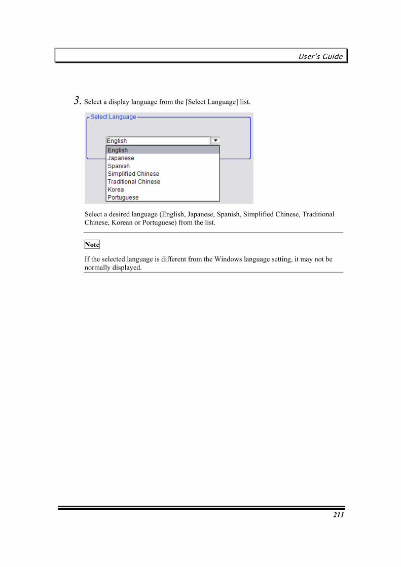
User’s Guide
211
3. Select a display language from the [Select Language] list.
Select a desired language (English, Japanese, Spanish, Simplified Chinese, Traditional Chinese, Korean or Portuguese) from the list.
Note
If the selected language is different from the Windows language setting, it may not be normally displayed.

Chapter 13 Various Settings of TRAPEZIUMX
212
Changing the startup screen
You can specify the screen to be displayed at startup by selecting the [Start Up /Auto Save] tab from the [Tools] – [Options] menu.
You can specify the startup screen according to the following procedure.
1. Click on [Tools] – [Options].
2. Click on the [Start Up /Auto Save] tab in the [Options] dialog box.
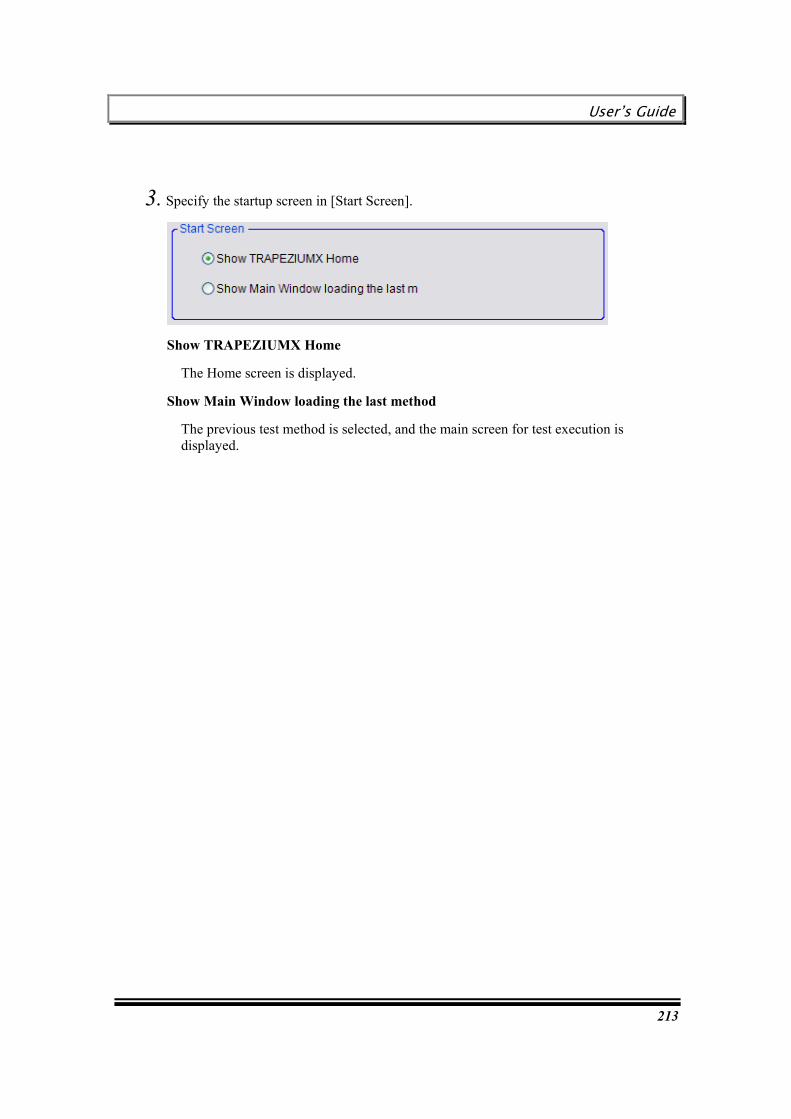
User’s Guide
213
3. Specify the startup screen in [Start Screen].
Show TRAPEZIUMX Home
The Home screen is displayed.
Show Main Window loading the last method
The previous test method is selected, and the main screen for test execution is displayed.
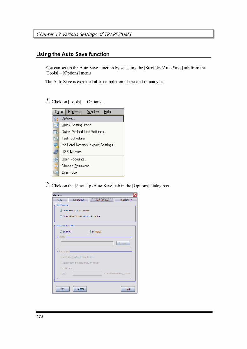
Chapter 13 Various Settings of TRAPEZIUMX
214
Using the Auto Save function
You can set up the Auto Save function by selecting the [Start Up /Auto Save] tab from the [Tools] – [Options] menu.
The Auto Save is executed after completion of test and re-analysis.
1. Click on [Tools] – [Options].
2. Click on the [Start Up /Auto Save] tab in the [Options] dialog box.

User’s Guide
215
3. Select “Enabled” in [Auto Save function].
4. Specify a storing place and file name.

Chapter 13 Various Settings of TRAPEZIUMX
216
Setting up software and testing machine operation logs
You can set up the log output function by selecting the [Log / Back up] tab from the [Tools] – [Options] menu.
You can set up operation logs according to the following procedure.
1. Click on [Tools] – [Options].
2. Click on the [Log / Back up] tab in the [Options] dialog box.

User’s Guide
217
3. Select “Enabled” in [Backup data function].
4. Specify the number of storing days in [Log] area.
The system stores logs for the number of days specified above. Logs older than the specified period will be deleted when this application is closed.
Purge Now!
Pressing this button immediately clears the logs stored before the specified period.

Chapter 13 Various Settings of TRAPEZIUMX
218
Setting up a test schedule
You can set up a schedule by selecting [Tools] - [Task Scheduler].
“Schedule” means a list that registers test orders. The system automatically executes tests according to this list.
You can set up a schedule according to the following procedure.
1. Click on [Tools] - [Task Scheduler].
2. Click on [Add].

User’s Guide
219
3. Select a method file, and click on [Open].
4. To delete a method, select a method file to be deleted, and click on [Delete].
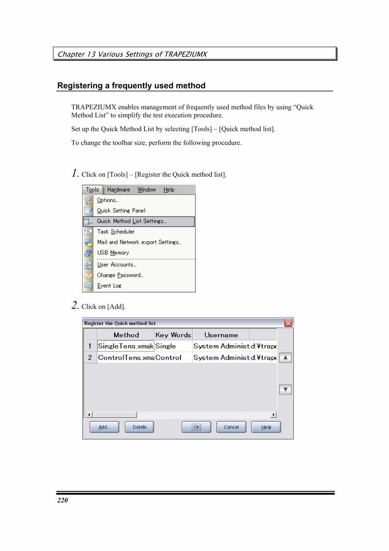
Chapter 13 Various Settings of TRAPEZIUMX
220
Registering a frequently used method
TRAPEZIUMX enables management of frequently used method files by using “Quick Method List” to simplify the test execution procedure.
Set up the Quick Method List by selecting [Tools] – [Quick method list].
To change the toolbar size, perform the following procedure.
1. Click on [Tools] – [Register the Quick method list].
2. Click on [Add].
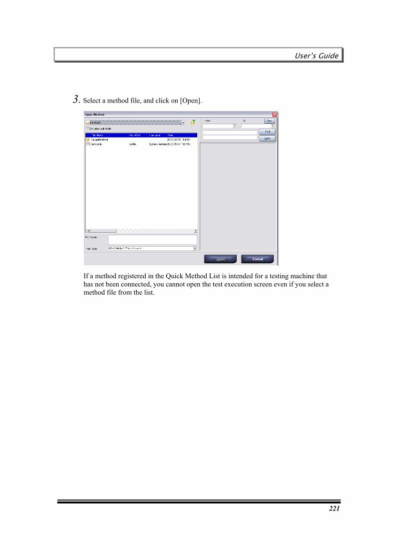
User’s Guide
221
3. Select a method file, and click on [Open].
If a method registered in the Quick Method List is intended for a testing machine that has not been connected, you cannot open the test execution screen even if you select a method file from the list.

Chapter 13 Various Settings of TRAPEZIUMX
222
This page is intentionally left blank.

User’s Guide
223
[Useful Functions]
[Useful Functions] describes various useful functions that can be executed with TRAPEZIUMX.

Chapter 14 Using USB Memory Function
224
Chapter 14 Using USB Memory Function
This chapter describes the USB Memory function that can be used with the touch panel of the AG-X Series AUTOGRAPH.
USB Memory function
Creating a method for the USB memory
Executing a test with the USB memory
Loading measurement data from the USB memory
Note
The USB memory must use the one with which the virus has not been infected.

User’s Guide
225
USB Memory function
The USB Memory function is used to save method and raw measurement data into the USB memory. With this function, a testing machine can singly execute test, without connection to a PC.
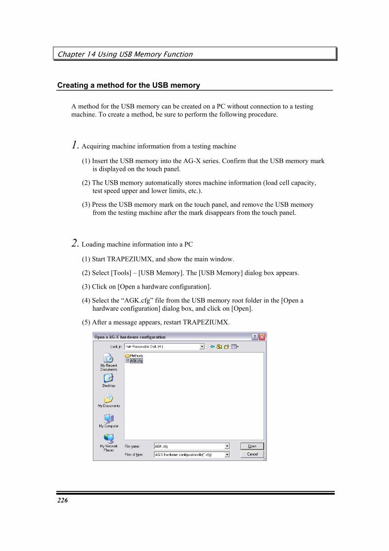
Chapter 14 Using USB Memory Function
226
Creating a method for the USB memory
A method for the USB memory can be created on a PC without connection to a testing machine. To create a method, be sure to perform the following procedure.
1. Acquiring machine information from a testing machine
(1) Insert the USB memory into the AG-X series. Confirm that the USB memory mark is displayed on the touch panel.
(2) The USB memory automatically stores machine information (load cell capacity, test speed upper and lower limits, etc.).
(3) Press the USB memory mark on the touch panel, and remove the USB memory from the testing machine after the mark disappears from the touch panel.
2. Loading machine information into a PC
(1) Start TRAPEZIUMX, and show the main window.
(2) Select [Tools] – [USB Memory]. The [USB Memory] dialog box appears.
(3) Click on [Open a hardware configuration].
(4) Select the “AGK.cfg” file from the USB memory root folder in the [Open a hardware configuration] dialog box, and click on [Open].
(5) After a message appears, restart TRAPEZIUMX.
User’s Guide
227
Note
Before using this function for the first time, be sure to perform the above Step 1 and Step 2. Also, after load cell replacement, be sure to perform these steps.
If you skip these steps, you cannot create a method corresponding to your testing machine.
3. Creating a method
Create a new method with TRAPEZIUMX, or open an existing method file.
RRReeelllaaattteeeddd kkkeeeyyywwwooorrrddd : “[Creating Method]”
Note
With a method for the USB memory, only a single specimen can be registered. Even if several specimen settings exist, they will be changed to a single specimen when they are saved.
You cannot change over several control areas with the settings in the [Testing] dialog box. Even if several control area settings exist, only the first area is active during test execution.
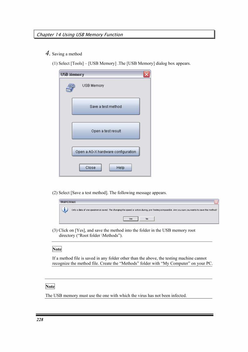
Chapter 14 Using USB Memory Function
228
4. Saving a method
(1) Select [Tools] – [USB Memory] .The [USB Memory] dialog box appears.
(2) Select [Save a test method]. The following message appears.
(3) Click on [Yes], and save the method into the folder in the USB memory root directory (“Root folder \Methods”).
Note
If a method file is saved in any folder other than the above, the testing machine cannot recognize the method file. Create the “Methods” folder with “My Computer” on your PC.
Note
The USB memory must use the one with which the virus has not been infected.

User’s Guide
229
Executing a test with the USB memory
To execute a test with the method saved in the USB memory, perform the following procedure.
Perform the following procedure
1. Insert the USB memory into the testing machine.
2. Click on [File] on the touch panel.

Chapter 14 Using USB Memory Function
230
3. Select the [Ext. USB] tab, and select a method.
4. Click [Select], and the test method is read.
5. Return to the monitor screen, and execute a test.

User’s Guide
231
6. To execute a test with the same method, continue to start the next test. To execute a test with a different method, return to Step 2, and select a method.
7. After completion of all tests, press the USB mark, and remove the USB memory from the testing machine.
Note
The USB memory must use the one with which the virus has not been infected.
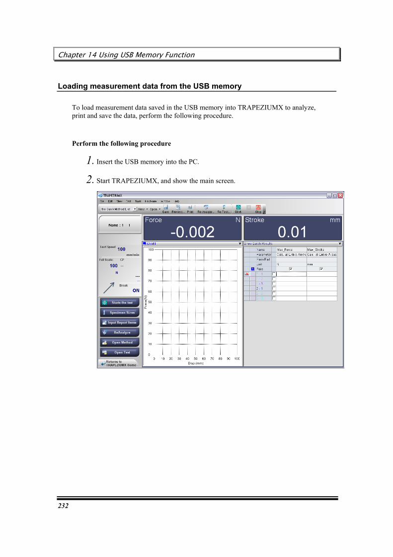
Chapter 14 Using USB Memory Function
232
Loading measurement data from the USB memory
To load measurement data saved in the USB memory into TRAPEZIUMX to analyze, print and save the data, perform the following procedure.
Perform the following procedure
1. Insert the USB memory into the PC.
2. Start TRAPEZIUMX, and show the main screen.

User’s Guide
233
3. Select [Tools] – [USB Memory]. The [USB Memory] dialog box appears.
4. Select [Open a test result].
5. The [Open Test] dialog box appears. Select all test files to be simultaneously displayed, and click on [Open].

Chapter 14 Using USB Memory Function
234
6. The selected test results are displayed on the main screen.
7. Save, re-analyze, print or export the test files, as required.
Note
The USB memory must use the one with which the virus has not been infected.
User’s Guide
235
Chapter 15 Using Statistical Process Control Function
This function is used to sample test results obtained with TRAPEZIUMX at specified intervals, to create a histogram or Xbar-R control chart.
This function enables simplified statistical process control (SPC) of measurement data.
TRAPEZIUMX acquires statistical data on routine test results by various terms (date, specimen, batch, etc.), and displays the statistical data on the screen. Furthermore, you can insert text into the statistical data for the purpose of printing or PFD file export.
Specifying the use of the statistical process control function and available functionality
(When using statistical process control function)
Setting rules for judging abnormalities
Creating a new control chart
Control chart (when using statistical process control function)
Opening a SPC/SQC data file (when using statistical process control function)
(When not using statistical process control function)
Creating a new histogram/control chart
Histogram
Control chart (when not using statistical process control function)
Opening a SPC/SQC data file (when not using statistical process control function)
Printing a histogram/control chart
Saving a histogram/control chart as a PDF file
Saving a histogram/control chart
Note
The statistical process control function [Enabled] / [Disabled] setting is specified via the setting dialog box that is displayed when the software is initially started. The setting can be confirmed in the [File] - [Tools] - [Options] window.
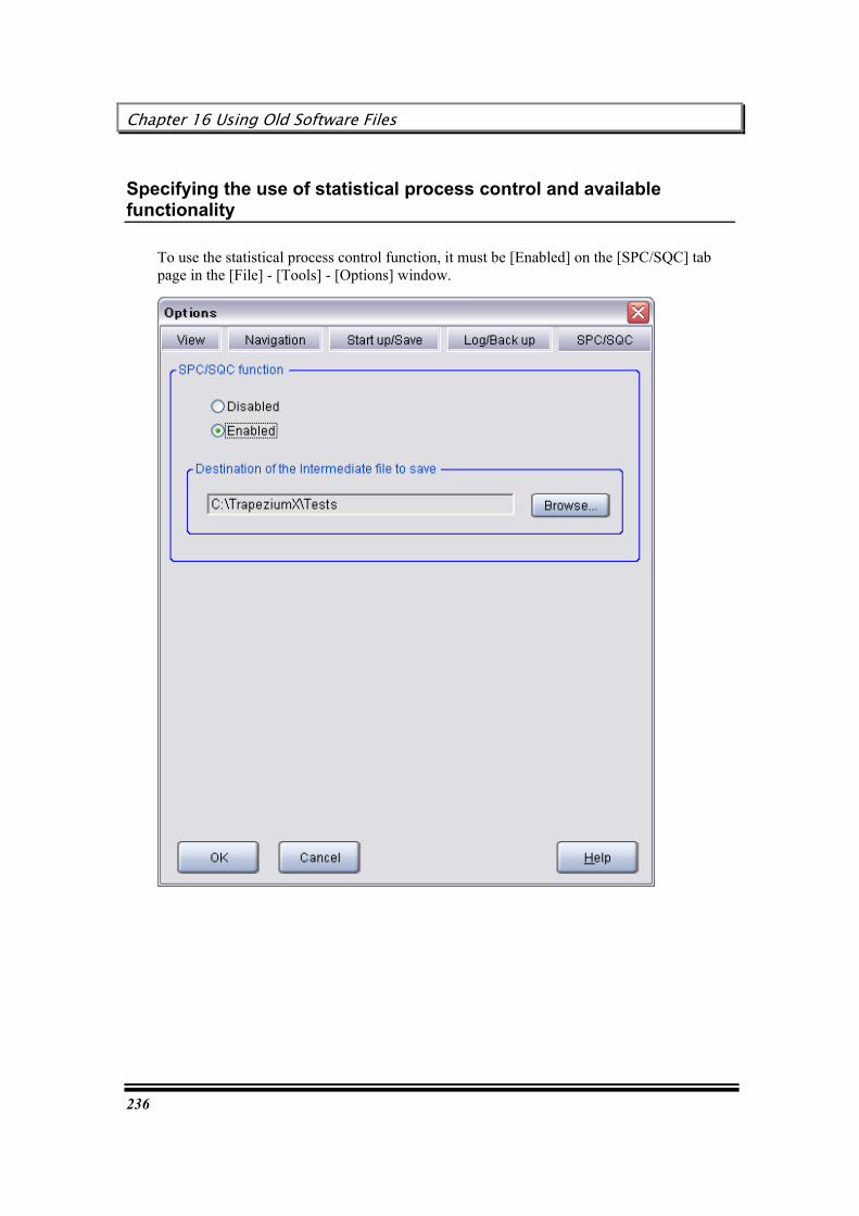
Chapter 16 Using Old Software Files
236
Specifying the use of statistical process control and available functionality
To use the statistical process control function, it must be [Enabled] on the [SPC/SQC] tab page in the [File] - [Tools] - [Options] window.
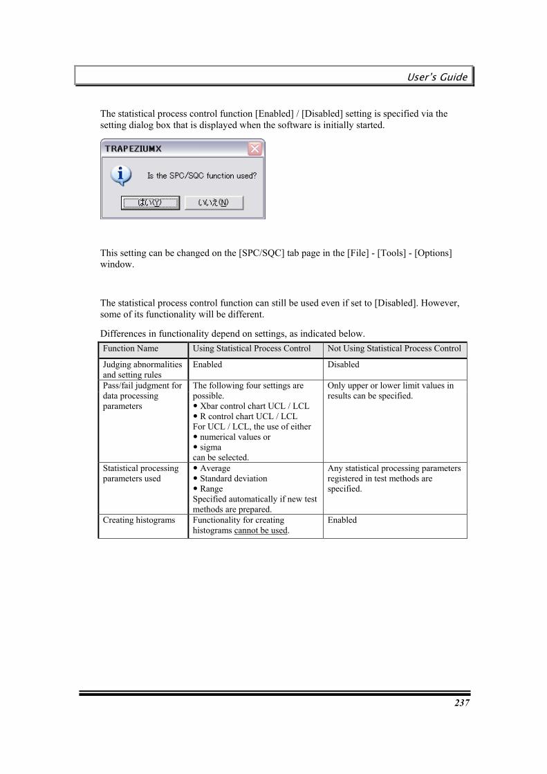
User’s Guide
237
The statistical process control function [Enabled] / [Disabled] setting is specified via the setting dialog box that is displayed when the software is initially started.
This setting can be changed on the [SPC/SQC] tab page in the [File] - [Tools] - [Options] window.
The statistical process control function can still be used even if set to [Disabled]. However, some of its functionality will be different.
Differences in functionality depend on settings, as indicated below. Function Name Using Statistical Process Control Not Using Statistical Process Control
Judging abnormalities and setting rules
Enabled Disabled
Pass/fail judgment for data processing parameters
The following four settings are possible. Xbar control chart UCL / LCL R control chart UCL / LCL For UCL / LCL, the use of either numerical values or sigma can be selected.
Only upper or lower limit values in results can be specified.
Statistical processing parameters used
Average Standard deviation Range Specified automatically if new test methods are prepared.
Any statistical processing parameters registered in test methods are specified.
Creating histograms Functionality for creating histograms cannot be used.
Enabled

Chapter 16 Using Old Software Files
238
Setting rules for judging abnormalities
To perform statistical process control requires specifying rules for judging whether or not there are any abnormalities in test results. These rules must be specified when test methods are prepared.
HHHiiinnnttt
This function is only available if the [Enabled] setting is specified for the statistical process control function.
Perform the following procedure.
1. Start Trapezium X and click [Create new method] in the TRAPEZIUM X home window.
2. Click the [Rules of unusual judging] button on the [System] tab page.
3. The [Rules of unusual judging] dialog box is displayed.
4. Select the checkboxes corresponding to the rules to be used.
HHHiiinnnttt
Rules can also be specified by clicking [File] - [Test] - [ReAnalyze] in the main screen.
For more information regarding respective criteria rule settings, refer to the software reference manual.
RRReeelllaaattteeeddd kkkeeeyyywwwooorrrddd : Software Reference Manual "[Rules of unusual judging] Dialog Box"

User’s Guide
239
Creating a new control chart
To create a histogram and control chart based on TRAPEZIUM X test results, perform the following procedure.
HHHiiinnnttt
This function is only available if the [Enabled] setting is specified for the statistical process control function.
Perform the following procedure.
1. Show the main screen.
2. Select [File] – [New] – [SPC/SQC].
3. The [Start SPC/SQC function: Find Test files] dialog box appears.

Chapter 16 Using Old Software Files
240
4. Search for a file, and mark the checkboxes for all data items subjected to process control.
RRReeelllaaattteeeddd kkkeeeyyywwwooorrrddd : Software Reference Manual"[Start SPC/SQC function] Dialog Box"
5. Click [Open].
6. The [SPC/SQC] dialog box appears.
7. Set up each function and execute printing with the navigation buttons on the left of the screen.
RRReeelllaaattteeeddd kkkeeeyyywwwooorrrddd : Software Reference Manual "[SPC/SQC] Dialog Box (when using statistical process control function)"
8. To quit the SPC/SQC function, click on [Close].
HHHiiinnnttt
To search for a file again, click on [Return to File Dialog]. Then, you will return to Step 3 above.

User’s Guide
241
Control chart (when using statistical process control function)
Control chart is used to compare measurement data with preset upper and lower limits to check for time-series changes in the measurement data.
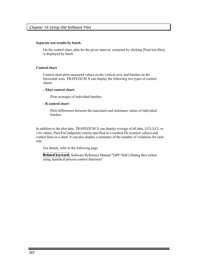
Chapter 16 Using Old Software Files
242
Separate test results by batch.
On the control chart, data for the given interval, extracted by clicking [Find test files], is displayed by batch.
Control chart
Control chart plots measured values on the vertical axis, and batches on the horizontal axes. TRAPEZIUM X can display the following two types of control charts:
- Xbar control chart:
Plots averages of individual batches.
- R control chart:
Plots differences between the maximum and minimum values of individual batches.
In addition to the plot data, TRAPEZIUM X can display average of all data, UCL/LCL or ±3s values, Pass/Fail judgment criteria specified in a method file (control values) and control lines in a chart. It can also display a summary of the number of violations for each rule.
For details, refer to the following page
RRReeelllaaattteeeddd kkkeeeyyywwwooorrrddd : Software Reference Manual "[SPC/SQC] Dialog Box (when using statistical process control function)"

User’s Guide
243
Opening a SPC/SQC data file (when using statistical process control function)
To open a saved SPC/SQC data file, perform the following procedure.
Either "*.sspc" or "*.sxspc" type files can be opened.
1. Show the main screen.
2. Select [File] – [Open] – [SPC/SQC].
3. The [Open SPC/SQC Data File] dialog box appears.
4. Select a file, and click [Open].
5. A saved histogram or control chart is displayed.
HHHiiinnnttt
Files can also be opened by clicking [File] - [Recent SPC/SQC Data].
HHHiiinnnttt
"*.sspc" type files are created automatically when test result files are saved.
These have the same name as the corresponding test result file.
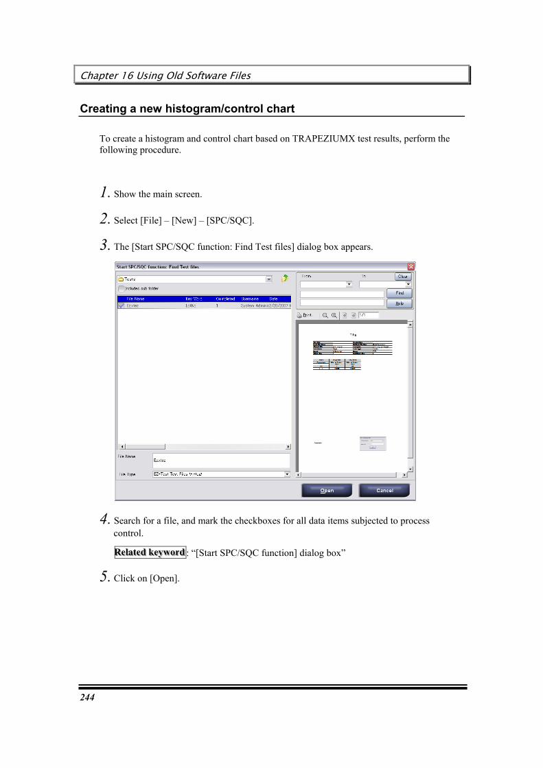
Chapter 16 Using Old Software Files
244
Creating a new histogram/control chart
To create a histogram and control chart based on TRAPEZIUMX test results, perform the following procedure.
1. Show the main screen.
2. Select [File] – [New] – [SPC/SQC].
3. The [Start SPC/SQC function: Find Test files] dialog box appears.
4. Search for a file, and mark the checkboxes for all data items subjected to process control.
RRReeelllaaattteeeddd kkkeeeyyywwwooorrrddd : “[Start SPC/SQC function] dialog box”
5. Click on [Open].
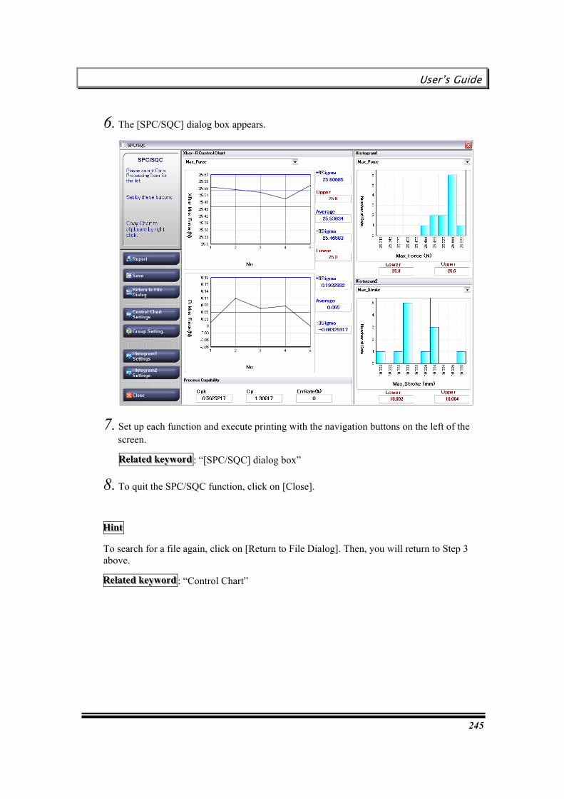
User’s Guide
245
6. The [SPC/SQC] dialog box appears.
7. Set up each function and execute printing with the navigation buttons on the left of the screen.
RRReeelllaaattteeeddd kkkeeeyyywwwooorrrddd : “[SPC/SQC] dialog box”
8. To quit the SPC/SQC function, click on [Close].
HHHiiinnnttt
To search for a file again, click on [Return to File Dialog]. Then, you will return to Step 3 above.
RRReeelllaaattteeeddd kkkeeeyyywwwooorrrddd : “Control Chart”
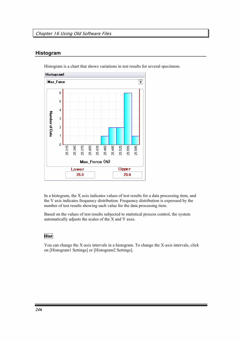
Chapter 16 Using Old Software Files
246
Histogram
Histogram is a chart that shows variations in test results for several specimens.
In a histogram, the X axis indicates values of test results for a data processing item, and the Y axis indicates frequency distribution. Frequency distribution is expressed by the number of test results showing each value for the data processing item.
Based on the values of test results subjected to statistical process control, the system automatically adjusts the scales of the X and Y axes.
HHHiiinnnttt
You can change the X-axis intervals in a histogram. To change the X-axis intervals, click on [Histogram1 Settings] or [Histogram2 Settings].
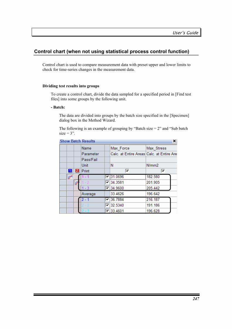
User’s Guide
247
Control chart (when not using statistical process control function)
Control chart is used to compare measurement data with preset upper and lower limits to check for time-series changes in the measurement data.
Dividing test results into groups
To create a control chart, divide the data sampled for a specified period in [Find test files] into some groups by the following unit.
- Batch:
The data are divided into groups by the batch size specified in the [Specimen] dialog box in the Method Wizard.
The following is an example of grouping by “Batch size = 2” and “Sub batch size = 3”.
Chapter 16 Using Old Software Files
248
- Test date:
Regardless of the “Batch size” and “Sub batch size” settings, all data on the tests executed on the same date are defined as one group.
- Test month:
Regardless of the “Batch size” and “Sub batch size” settings, all data on the tests executed in the same month are defined as one group.
HHHiiinnnttt
To change the group division setting, click on [Group Setting].
RRReeelllaaattteeeddd kkkeeeyyywwwooorrrddd : “[Group Setting] dialog box”
Control chart
Control chart plots measured values on the vertical axis, and group numbers on the horizontal axes. TRAPEZIUMX can display the following two types of control charts:
- Xbar control chart:
Plots averages of individual groups.
- R control chart:
Plots differences between the maximum and minimum values of individual groups.
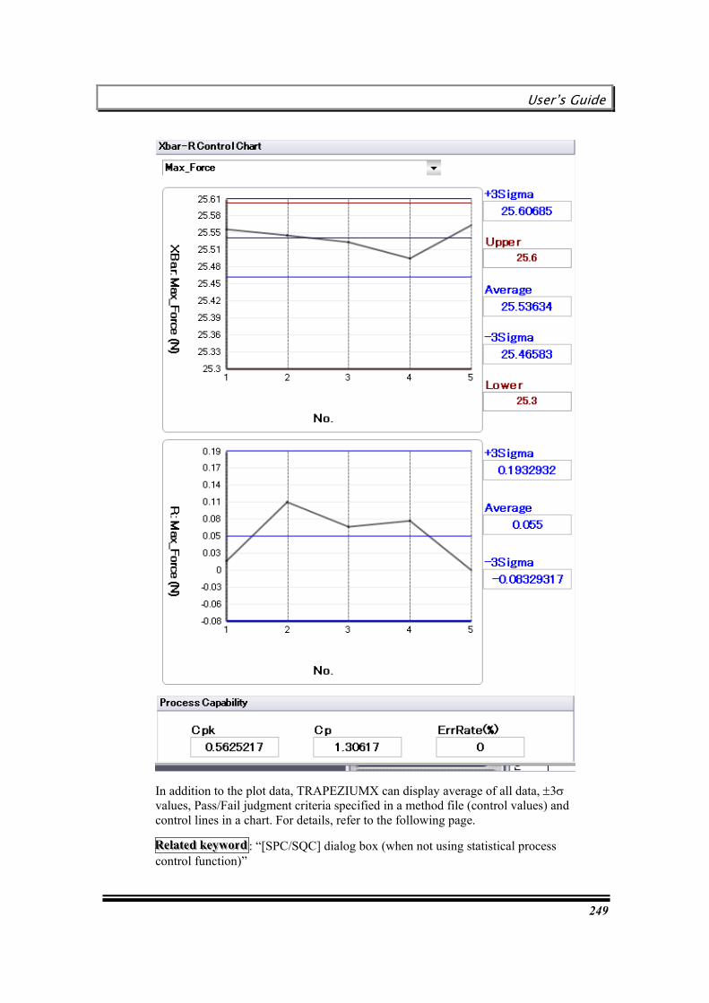
User’s Guide
249
In addition to the plot data, TRAPEZIUMX can display average of all data, ±3s values, Pass/Fail judgment criteria specified in a method file (control values) and control lines in a chart. For details, refer to the following page.
RRReeelllaaattteeeddd kkkeeeyyywwwooorrrddd : “[SPC/SQC] dialog box (when not using statistical process control function)”
Chapter 16 Using Old Software Files
250
Opening a SPC/SQC data file
To open a saved SPC/SQC data file, perform the following procedure.
"*.spc" type files can be opened.
1. Show the main screen.
2. Select [File] – [Open] – [SPC/SQC].
3. The [Open SPC/SQC Data File] dialog box appears.
4. Select a file, and click on [Open].
5. A saved histogram or control chart is displayed.
HHHiiinnnttt
Files can also be opened by clicking [File] - [Recent SPC/SQC Data].
Printing a histogram/control chart
Click on [Report], and create a report in the [SPC/SQC Report] dialog box.
RRReeelllaaattteeeddd kkkeeeyyywwwooorrrddd : “[SPC/SQC Report] dialog box”
Saving a histogram/control chart as a PDF file
Click on [PFD] in the [SPC/SQC Report] dialog box.
RRReeelllaaattteeeddd kkkeeeyyywwwooorrrddd : “[SPC/SQC Report] dialog box”
Saving a histogram/control chart
Click on [Save] in the [SPC/SQC Report] dialog box.

User’s Guide
251
Chapter 16 Using Old Software Files
Test method and result files created in TRAPEZIUM2 can be opened from TRAPEZIUMX.
This chapter describes the procedure to recycle files created in old software.
Before using TRAPEZIUM2 files
Open method files created in TRAPEZIUM2
Open test files created in TRAPEZIUM2
Convert from TRAPEZIUM2 file to TRAPEZIUMX file
Notes of TRAPEZIUM2 file conversion

Chapter 16 Using Old Software Files
252
Before using TRAPEZIUM2 files
Before you use method files or test files created in TRAPEZIUM2, confirm testing machine corresponding to those files is registered.
And, if two or more testing machines are registered, confirm that has been selected in [Hardware Settings] dialog box, which is the testing machine corresponding to those files that you wish to use.
The testing machine corresponding to files
The extension of the file and the testing machine corresponding to it are as follows. Test machine type Extension of test file Extension of method file
AG-IS,I,EZGraph *.tai *.mai AGS-J,H *.tah *.mah EZTest *.tez *.mez EZ-L,S *.tes, *.tel *.mes, *.mel
How to register the testing machine
1. Prepare a simple method, and display the main window.
RRReeelllaaattteeeddd kkkeeeyyywwwooorrrddd : “Creating Method”
2. Select [Hardware] - [Registration of Testing machines and jigs].
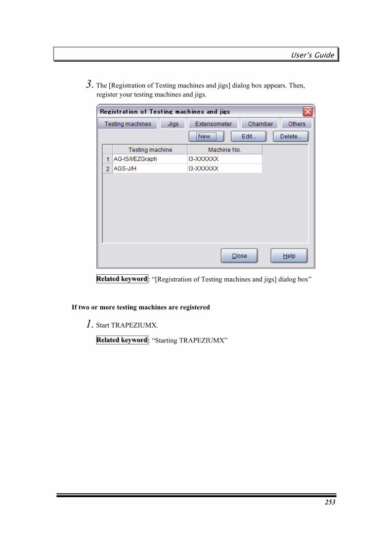
User’s Guide
253
3. The [Registration of Testing machines and jigs] dialog box appears. Then, register your testing machines and jigs.
RRReeelllaaattteeeddd kkkeeeyyywwwooorrrddd : “[Registration of Testing machines and jigs] dialog box”
If two or more testing machines are registered
1. Start TRAPEZIUMX.
RRReeelllaaattteeeddd kkkeeeyyywwwooorrrddd : “Starting TRAPEZIUMX”

Chapter 16 Using Old Software Files
254
2. Clicking [Hardware Settings], display [Hardware Settings] dialog box.
3. Select [Testing machine/ PC Settings] tab.
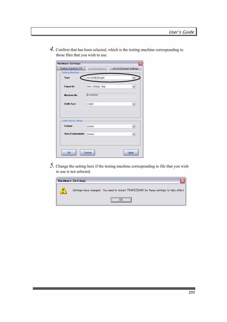
User’s Guide
255
4. Confirm that has been selected, which is the testing machine corresponding to those files that you wish to use.
5. Change the setting here if the testing machine corresponding to file that you wish to use is not selected.

Chapter 16 Using Old Software Files
256
Open method files created in TRAPEZIUM2
Method files created in TRAPEZIUM2 can be opened by perform the following procedure.
Perform the following procedure
1. Click [Open Method] in the [TRAPEZIUMX Home] window.
2. Select [Old Software Type] in the [Open Method] dialog box.
3. The file specified in “File Type” is displayed in the list.

User’s Guide
257
4. Click [Open] specifying the file.
5. The [Method] Wizard will be displayed, confirm those settings.
HHHiiinnnttt
When clicking [Test with this method], can be testing this method.
When clicking [Save a Method file], can be preserved in TRAPEZIUMX type.
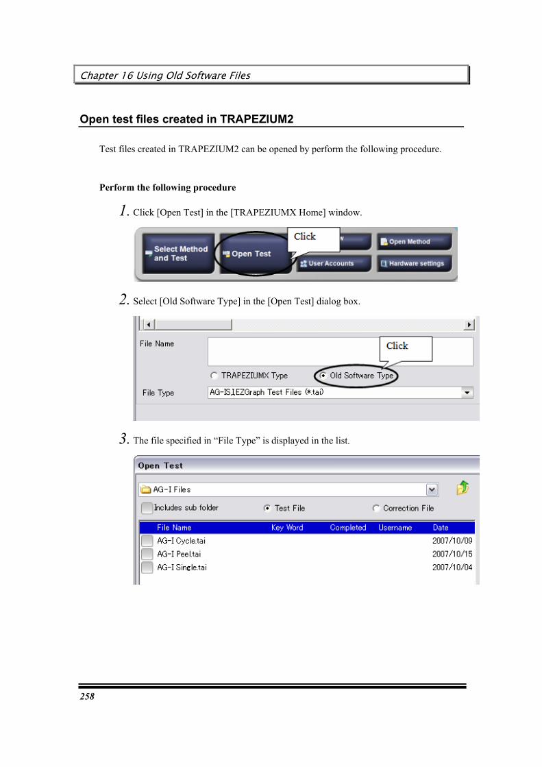
Chapter 16 Using Old Software Files
258
Open test files created in TRAPEZIUM2
Test files created in TRAPEZIUM2 can be opened by perform the following procedure.
Perform the following procedure
1. Click [Open Test] in the [TRAPEZIUMX Home] window.
2. Select [Old Software Type] in the [Open Test] dialog box.
3. The file specified in “File Type” is displayed in the list.
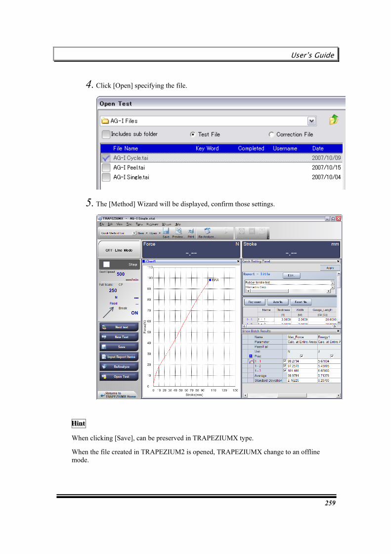
User’s Guide
259
4. Click [Open] specifying the file.
5. The [Method] Wizard will be displayed, confirm those settings.
HHHiiinnnttt
When clicking [Save], can be preserved in TRAPEZIUMX type.
When the file created in TRAPEZIUM2 is opened, TRAPEZIUMX change to an offline mode.
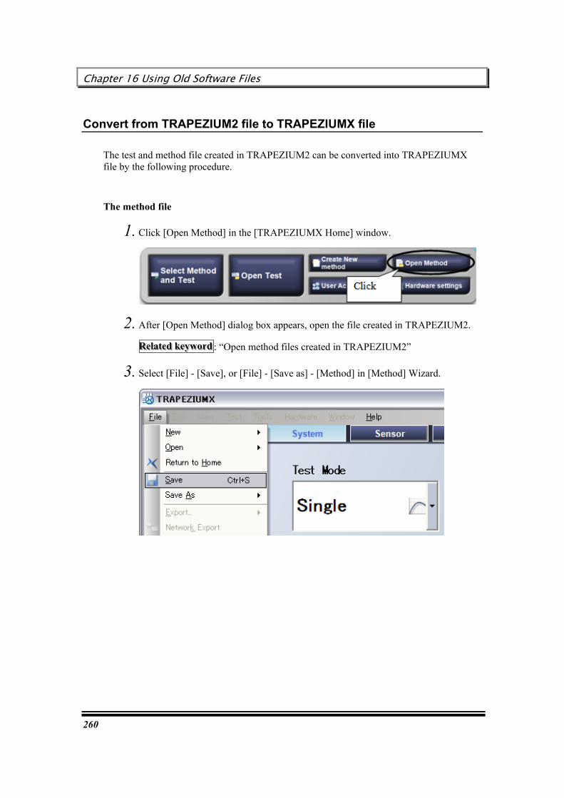
Chapter 16 Using Old Software Files
260
Convert from TRAPEZIUM2 file to TRAPEZIUMX file
The test and method file created in TRAPEZIUM2 can be converted into TRAPEZIUMX file by the following procedure.
The method file
1. Click [Open Method] in the [TRAPEZIUMX Home] window.
2. After [Open Method] dialog box appears, open the file created in TRAPEZIUM2.
RRReeelllaaattteeeddd kkkeeeyyywwwooorrrddd : “Open method files created in TRAPEZIUM2”
3. Select [File] - [Save], or [File] - [Save as] - [Method] in [Method] Wizard.
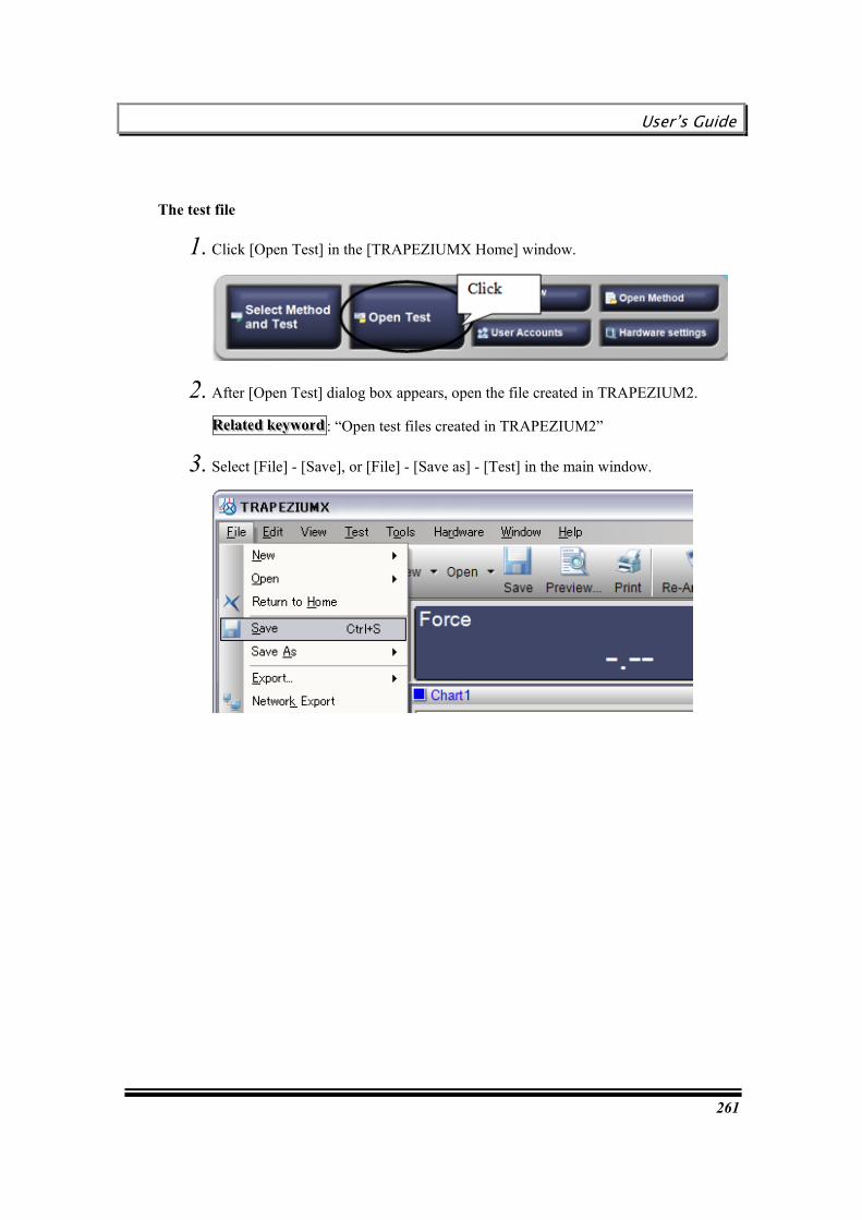
User’s Guide
261
The test file
1. Click [Open Test] in the [TRAPEZIUMX Home] window.
2. After [Open Test] dialog box appears, open the file created in TRAPEZIUM2.
RRReeelllaaattteeeddd kkkeeeyyywwwooorrrddd : “Open test files created in TRAPEZIUM2”
3. Select [File] - [Save], or [File] - [Save as] - [Test] in the main window.

Chapter 16 Using Old Software Files
262
Notes of TRAPEZIUM2 file conversion
Please note the following content when you convert the TRAPEZIUM2 file into a TRAPEZIUMX file.
The file which can be converted into TRAPEZIUMX type
Files which can be converted into TRAPEZIUMX type are only files created in “Single software” and “Cycle software”.
Files which are created in “Control software” or “TRAPEZIUM Rehometer” cannot be converted into TRAPEZIUMX type.
The file including [Compli.] in [Test Type] can’t be converted.
Files including [Compli.] in [Test Type] cannot be converted into TRAPEZIUMX type.
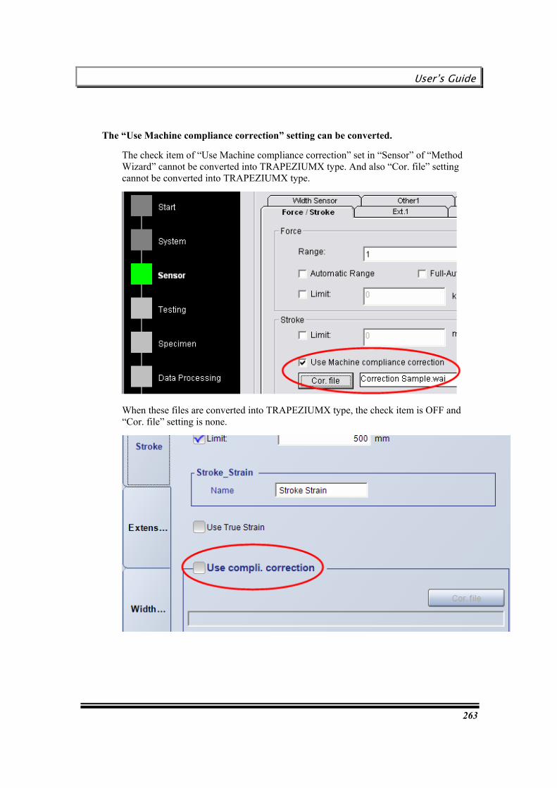
User’s Guide
263
The “Use Machine compliance correction” setting can be converted.
The check item of “Use Machine compliance correction” set in “Sensor” of “Method Wizard” cannot be converted into TRAPEZIUMX type. And also “Cor. file” setting cannot be converted into TRAPEZIUMX type.
When these files are converted into TRAPEZIUMX type, the check item is OFF and “Cor. file” setting is none.

Chapter 16 Using Old Software Files
264
The “Get data every” setting can be converted.
The “Get data every” setting set in “Data Processing” of “Method Wizard” cannot be converted into TRAPEZIUMX type.
When these files are converted into TRAPEZIUMX type, the data processing items are calculated by using all cycles.
The template of Excel Report cannot be used.
The template of Excel Report created by the version before TRAPEZIUM2 cannot be used with TRAPEZIUMX.
The TRAPEZIUM2 file is not added to the list of “Recent files”.
When the TRAPEZIUM2 file is opened, its file is not added to “Recent Methods” or “Recent Tests”.
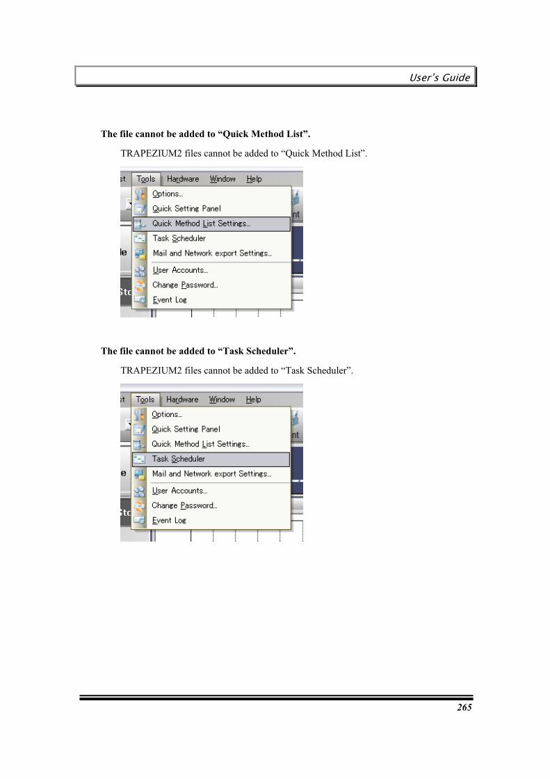
User’s Guide
265
The file cannot be added to “Quick Method List”.
TRAPEZIUM2 files cannot be added to “Quick Method List”.
The file cannot be added to “Task Scheduler”.
TRAPEZIUM2 files cannot be added to “Task Scheduler”.

Chapter 16 Using Old Software Files
266
This page is intentionally left blank.
User’s Guide
267
Chapter 17 Marker Controller Function
During testing, maximum 20 point can get by pushing [Marker Controller Switch (Optional Accesory)] or [KeyBoard of PC]..
This chapter describes the procedure to use the “Marker Controller Function”.
Before using TRAPEZIUM2 files
Settings for using [Marker Contoller Switch] for EZ-LS or AGS-J (Optional)
Operation during testing
“Marker Controller function” by using “PC Keyboard” can be used for all types of testing machine.
By using “Marker Controller Switch(Optional)” can be used only for [AG-Xplus][AG-X][EZ-L,S]or [AGS-J]
The “Marker Controller Swtich” for [EZ-L,S] [AGS-J] is the custome made model.
The “Marker Controller Switch” for [AG-IS] or other testing machines cannot be used.
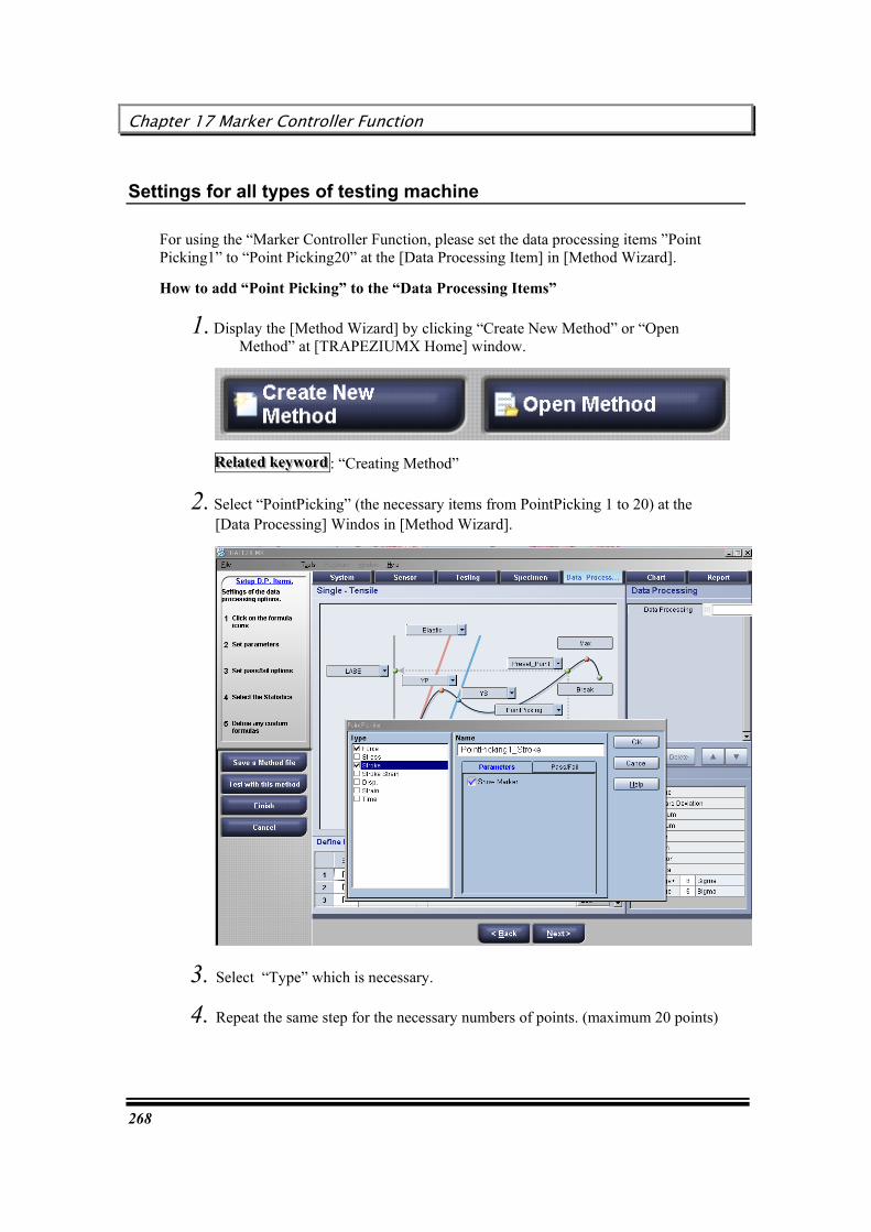
Chapter 17 Marker Controller Function
268
Settings for all types of testing machine
For using the “Marker Controller Function, please set the data processing items ”Point Picking1” to “Point Picking20” at the [Data Processing Item] in [Method Wizard].
How to add “Point Picking” to the “Data Processing Items”
1. Display the [Method Wizard] by clicking “Create New Method” or “Open Method” at [TRAPEZIUMX Home] window.
RRReeelllaaattteeeddd kkkeeeyyywwwooorrrddd : “Creating Method”
2. Select “PointPicking” (the necessary items from PointPicking 1 to 20) at the [Data Processing] Windos in [Method Wizard].
3. Select “Type” which is necessary.
4. Repeat the same step for the necessary numbers of points. (maximum 20 points)
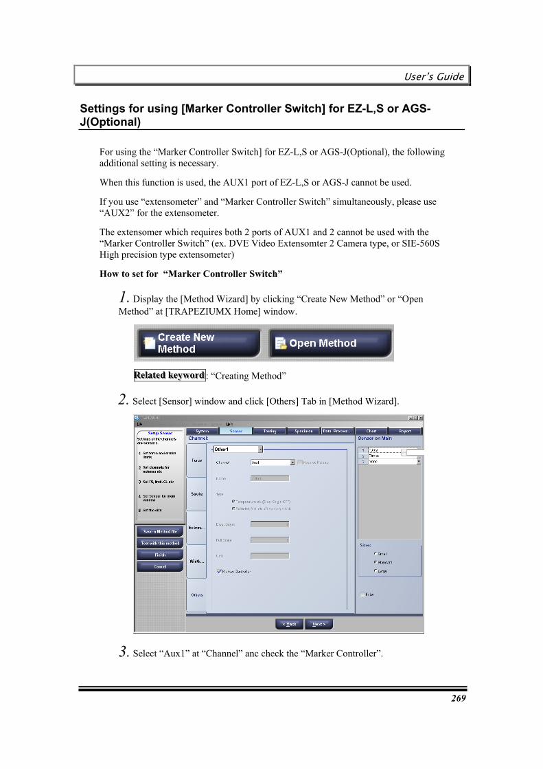
User’s Guide
269
Settings for using [Marker Controller Switch] for EZ-L,S or AGS-J(Optional)
For using the “Marker Controller Switch] for EZ-L,S or AGS-J(Optional), the following additional setting is necessary.
When this function is used, the AUX1 port of EZ-L,S or AGS-J cannot be used.
If you use “extensometer” and “Marker Controller Switch” simultaneously, please use “AUX2” for the extensometer.
The extensomer which requires both 2 ports of AUX1 and 2 cannot be used with the “Marker Controller Switch” (ex. DVE Video Extensomter 2 Camera type, or SIE-560S High precision type extensometer)
How to set for “Marker Controller Switch”
1. Display the [Method Wizard] by clicking “Create New Method” or “Open Method” at [TRAPEZIUMX Home] window.
RRReeelllaaattteeeddd kkkeeeyyywwwooorrrddd : “Creating Method”
2. Select [Sensor] window and click [Others] Tab in [Method Wizard].
3. Select “Aux1” at “Channel” anc check the “Marker Controller”.

Chapter 17 Marker Controller Function
270
Operation during testing
The operation during testing is as follows.
For using [Marker Contoller Switch (Optional)] Push the switch connected to the testing machine.
For using [PC Keyboard] Push the keyboard “Space Key” or “Alphabet Key” except “Function Key(F1 – F12)”.

User’s Guide
271
Chapter 18 Using Initial Speed function
This chapter describes about the procedures for using the initial speed function.
This function can be used only for EZ-X, AGS-X, AG-X.When EZ-S/L (old model of EZTest), AGS-J/H, AG-IS is used, this function cannot be used.
Addition it, this function can be used only Contorol or Texture mode.
General introduction of this function
How to set test method

Chapter18 Using Initial Speed function
272
General Introduction of this function
This function can be set the “Initial Speed” for testing.
Initial Speed is the speed at the beginning of the test.
This speed starts from the beginning of the test to arrive at the “Displacement origin”.
During the initial speed area, sampling data is not recorded, just after arriving at the “displacement origin force”, sampling data is started to record.
Note
This function can be used only for EZ-X, AGS-X, AG-X.When EZ-S/L (old model of EZTest), AGS-J/H, AG-IS is used, this function cannot be used.
Addition it, this function can be used only with Contorol or Texture mode.
Force(N)
Displacement(mm)
Displacement Origin Force
Moving with the Initial Speed
Moving with the test Speed

User’s Guide
273
How to set test method for initial speed
The section describes how to testing method to use the “Initial Speed Function”.
1. Open test method file or create new method.
2. Select [Testing] Tab and click [Details].
3. The [ActDetails] Screen is diplayed.
4. Set the ON/OFF checkbox to [ON] and enter the Initial speed.
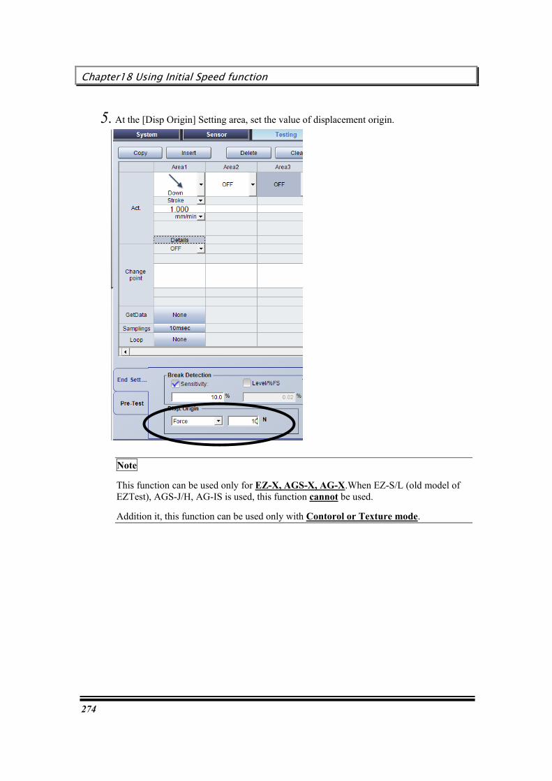
Chapter18 Using Initial Speed function
274
5. At the [Disp Origin] Setting area, set the value of displacement origin.
Note
This function can be used only for EZ-X, AGS-X, AG-X.When EZ-S/L (old model of EZTest), AGS-J/H, AG-IS is used, this function cannot be used.
Addition it, this function can be used only with Contorol or Texture mode.

User’s Guide
275
Chapter 19 Measuring the Clearance function
This chapter describes about the function of “Measuring Clearance”.
To perform the test by using measuring Clearance, detecting the“Origin(zero point)” of “Clearance” is necessary.
2 types of detection can be performed in this software.
This function can be used only for EZ-X, AGS-X, AG-X.When EZ-S/L (old model of EZTest), AGS-J/H, AG-IS is used, this function cannot be used.
Addition it, this function can be use only with Texture mode.
Introduction of the Clearance
What is the “Detection of the Clearance Origin
Automatic detection of the Clearance Origin
Manual detection of the Clearance Origin
How to set Test Method
WARNING : About Return and Position Zero
ATTENTION : About digital value display
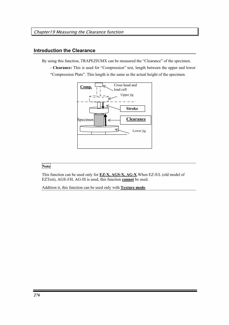
Chapter19 Measuring the Clearance function
276
Introduction the Clearance
By using this function, TRAPEZIUMX can be measured the “Clearance” of the specimen. - Clearance: This is used for “Compression” test, length between the upper and lower “Compression Plate”. This length is the same as the actual height of the specimen.
Note
This function can be used only for EZ-X, AGS-X, AG-X.When EZ-S/L (old model of EZTest), AGS-J/H, AG-IS is used, this function cannot be used.
Addition it, this function can be used only with Texture mode.
Comp.
Lower jig
Upper jig
Cross head and load cell
Specimen Clearance
Stroke
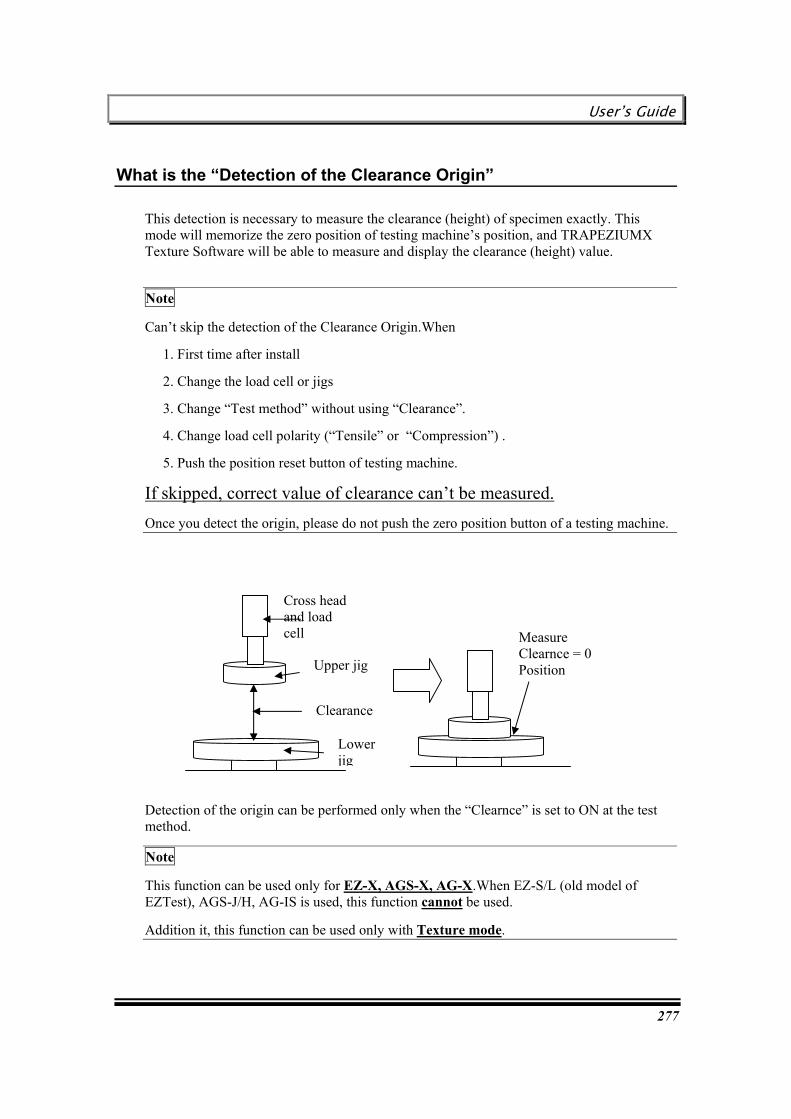
User’s Guide
277
What is the “Detection of the Clearance Origin”
This detection is necessary to measure the clearance (height) of specimen exactly. This mode will memorize the zero position of testing machine’s position, and TRAPEZIUMX Texture Software will be able to measure and display the clearance (height) value.
Note
Can’t skip the detection of the Clearance Origin.When
1. First time after install
2. Change the load cell or jigs
3. Change “Test method” without using “Clearance”.
4. Change load cell polarity (“Tensile” or “Compression”) .
5. Push the position reset button of testing machine.
If skipped, correct value of clearance can’t be measured. Once you detect the origin, please do not push the zero position button of a testing machine.
Detection of the origin can be performed only when the “Clearnce” is set to ON at the test method.
Note
This function can be used only for EZ-X, AGS-X, AG-X.When EZ-S/L (old model of EZTest), AGS-J/H, AG-IS is used, this function cannot be used.
Addition it, this function can be used only with Texture mode.
Lower jig
Upper jig
Cross head and load cell
Clearance
Measure Clearnce = 0 Position

Chapter19 Measuring the Clearance function
278
Automatic detection of the Clearance Origin
TRAPEZIUM X can detect the origin automatically.
Following is the flow of automatic detection. (Example of the compression)
Operation_Step by Step
Before hand, please set “Use Clearance between jigs” at the Method Wizard.
1.Select [Hardware] – [Detect Height/Length/Clearance Origin] in the menu.
Flow
Lower jig
Upper jig
Cross head and load cell
Clearance
Compress upper and lower jig directly, and Measure the “Origin (zero point)” of the “Clearance”
Returns to the specified position

User’s Guide
279
2. [Detection of the "Height/Length/Clearance origin"] dialog is displayed.
3.Push jog button of testing machine to become the length between loading jigs nearer.
4. Set the Detection settings
- Select “Polarity(Compression or Tensile)” and “Direction(Up or Down)”
- Confirm “the point of detecting origin” :

Chapter19 Measuring the Clearance function
280
Set the value of “XX” % of the load cell capacity
5. Click [Start] button in this dialog.
6. [Detection of the "Height/Length/Clearance origin"] dialog is closed and the detection starts.
7. The detection is performed by the following flow. (Example of the Compression)
8. “The length between upper and lower jigs” at this point is saved.
9. The “Automatic detection” is completed. TRAPEZIUM X returns to the normal screen.
HHHiiinnnttt
Flow
Crosshead goes DOWN until the both jigs contacts by about 10mm/min
Speed is change and Returns to the specified position. The Position of the testing machine is ZERO RESET.
Speed is changed to 0.5mm/min and compress to 10 % of the load cell capacity
Crosshead goes UP and measure the origin of the clearance
The length of this point is saved as “Heght/Length at the position Zero” and displayed at [Detection of the "Height/Length origin"] dialog .

User’s Guide
281
*Clearrance vaue is shown at the Clearance sensor of software.
*The value of zero position of testing machine will be displayed at [Detection of the "Height/Length/Clearance origin"] dialog
Note
This function can be used only for EZ-X, AGS-X, AG-X.When EZ-S/L (old model of EZTest), AGS-J/H, AG-IS is used, this function cannot be used.
Addition it, this function can be used only with Texture mode.

Chapter19 Measuring the Clearance function
282
Manual detection of the Height / Length/Clearance Origin
The Height / Length /Clearance origin can be measured manually by using “Block gage” or “Caliper”
The following is the example of using “Block gage”
Note
This function can be used only for EZ-X, AGS-X, AG-X.When EZ-S/L (old model of EZTest), AGS-J/H, AG-IS is used, this function cannot be used.
Addition it, this function can be used only with Texture mode.
Prepare the Block gage which you already know the “Height” and set to the lower jig.
By “JOG Dial”, let the crosshead go down until the upper jigs contacts to the block gage.
Push the [Positon ZeroButton] of the testing machine.
Show [Detection of the "Height/Length/Clearance origin"] dialog, By Select [Hardware] – [Detect Height/Length/Clearance Origin] in the menu.
Input the “Height” of the “Block Gage” And click [Close]

User’s Guide
283
How to set Test method
This section describes how to set test method when the clearance function is necessay.
1. Open test method file or create new method.
2. Select [Sensor] Tab and click [Stroke].
3. Set the [Use Clearance between jigs] to ON.
4. Select [Clearance] at the [Sensor on Main].
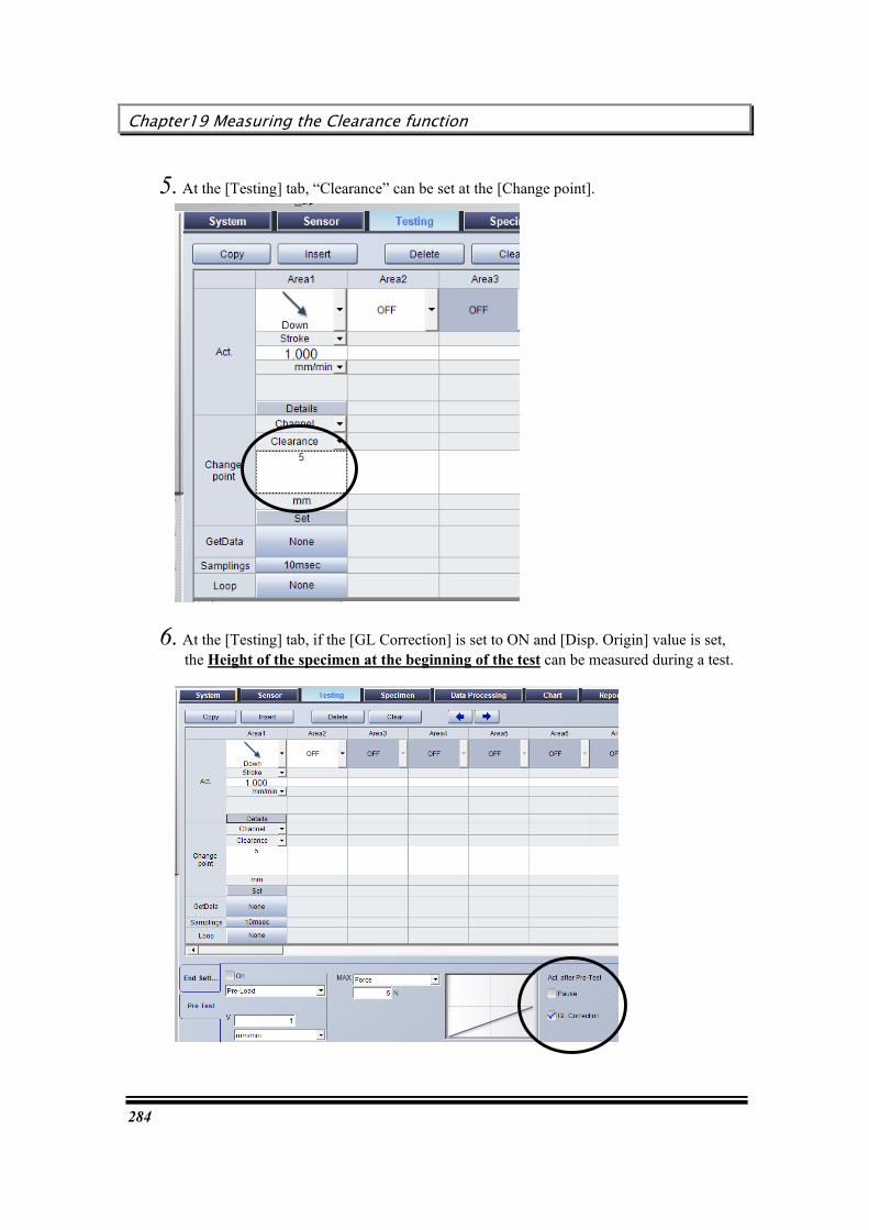
Chapter19 Measuring the Clearance function
284
5. At the [Testing] tab, “Clearance” can be set at the [Change point].
6. At the [Testing] tab, if the [GL Correction] is set to ON and [Disp. Origin] value is set, the Height of the specimen at the beginning of the test can be measured during a test.

User’s Guide
285
Height of the specimen at the beginning of the test is displayed at the [Specimen] Tab after a test.
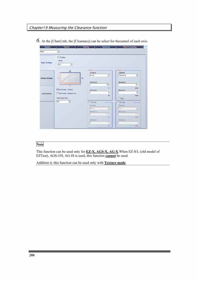
Chapter19 Measuring the Clearance function
286
6. At the [Chart] tab, the [Clearance] can be select for thecannel of each axis.
Note
This function can be used only for EZ-X, AGS-X, AG-X.When EZ-S/L (old model of EZTest), AGS-J/H, AG-IS is used, this function cannot be used.
Addition it, this function can be used only with Texture mode.
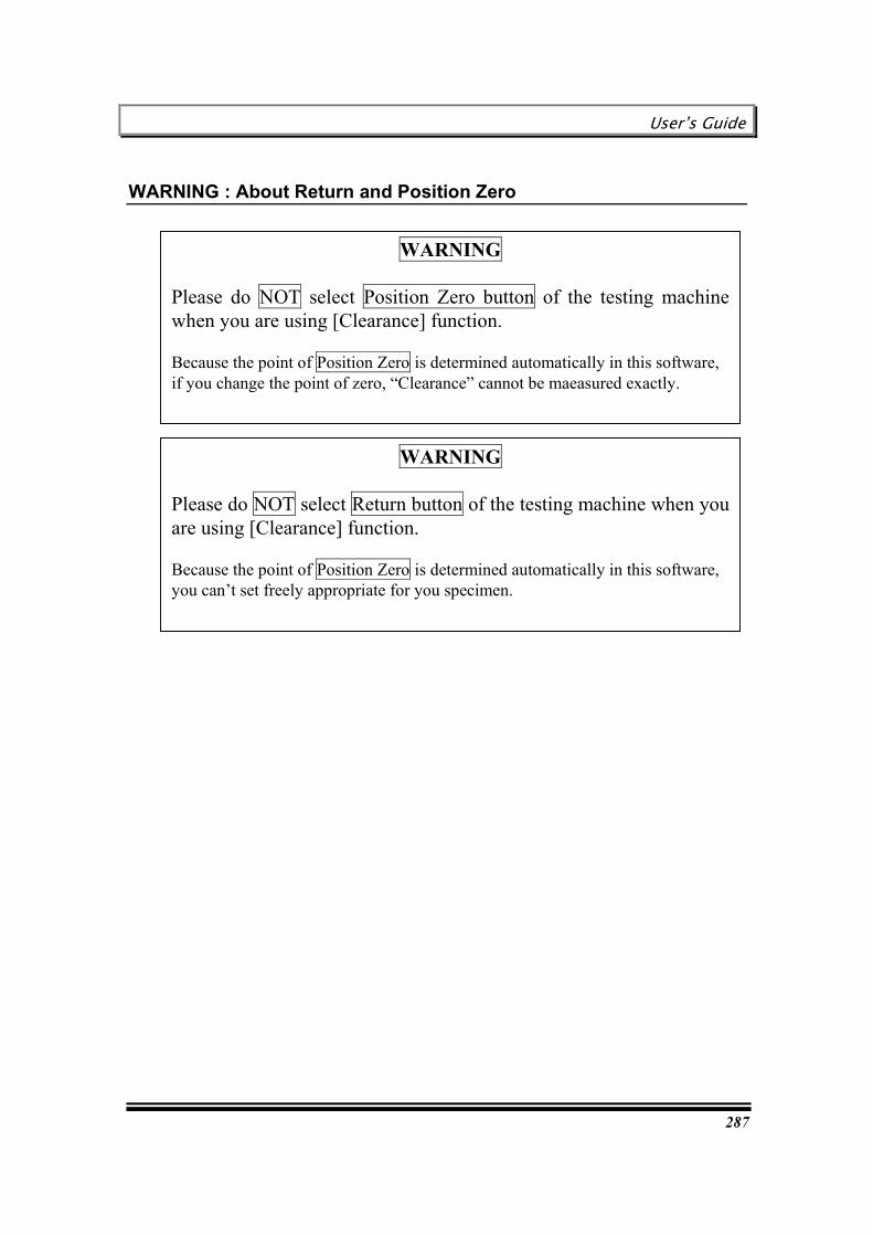
User’s Guide
287
WARNING : About Return and Position Zero
WARNING Please do NOT select Return button of the testing machine when you are using [Clearance] function.
Because the point of Position Zero is determined automatically in this software, you can’t set freely appropriate for you specimen.
WARNING Please do NOT select Position Zero button of the testing machine when you are using [Clearance] function.
Because the point of Position Zero is determined automatically in this software, if you change the point of zero, “Clearance” cannot be maeasured exactly.

Chapter19 Measuring the Clearance function
288
ATTENTION : About digital value displayy
Force value
Direction: tensile Indicates plus value when load cell is supplied tensional power.
Direction: compress Indicates plus value when load cell is supplied compressive power.
Clearance value
Indicates absolute value of the length from the zero point.
Stroke value
On testing: When the force value becomes [Disp. Origin], stroke value is zero reset. Indicates the length from this point. Before, after testing: Indicates the same value as testing machine.
User’s Guide
289
Chapter 20 Useful Functions for Texture software
This chapter describes about the new functions of the TRAPEZIUMX Texture Software.
Pre-Installed Methods
Area Filling function
Displaying Average curve per batch
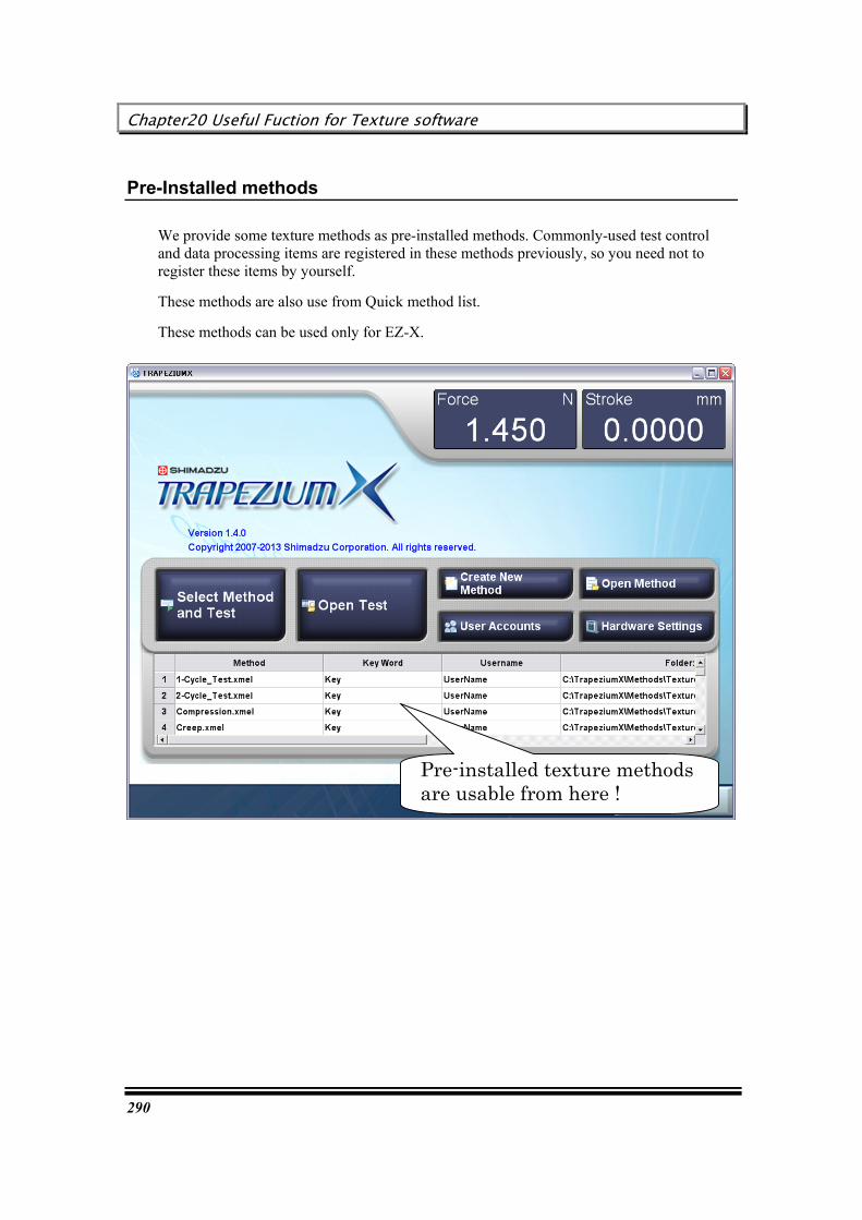
Chapter20 Useful Fuction for Texture software
290
Pre-Installed methods
We provide some texture methods as pre-installed methods. Commonly-used test control and data processing items are registered in these methods previously, so you need not to register these items by yourself.
These methods are also use from Quick method list.
These methods can be used only for EZ-X.
Pre-installed texture methods are usable from here !

User’s Guide
291
Area Filling fuction
Fill the areas with the color which are used for energy calculation.

Chapter20 Useful Fuction for Texture software
292
Show Average Curve per Batch
This function shows the average curve of the chart.
The previous version can show the average curve.This cuve is the average of all specimen.
The new function can show average curve separately by each batch.
For example, when the No. of Batches is set to “3”, the 3 curves can be shown.
To show the average curve, right click on the chart and select [Average curve per Batch]
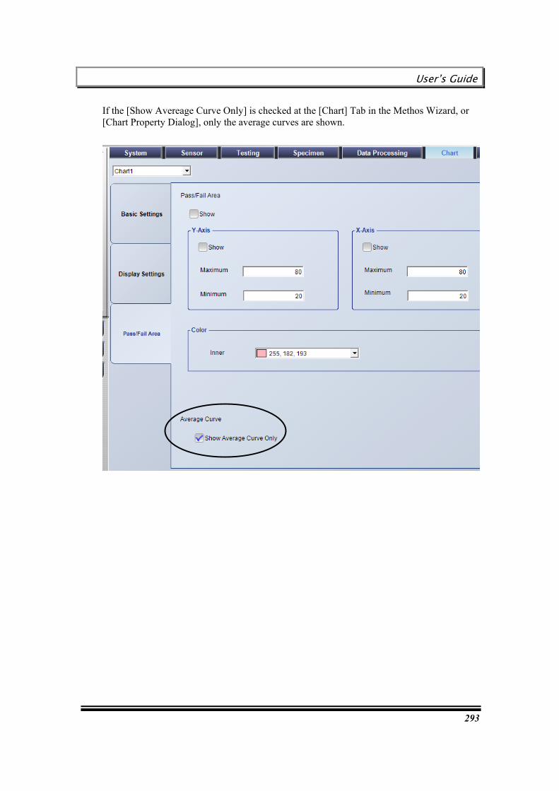
User’s Guide
293
If the [Show Avereage Curve Only] is checked at the [Chart] Tab in the Methos Wizard, or [Chart Property Dialog], only the average curves are shown.

Chapter20 Useful Fuction for Texture software
294
This page is intentionally left blank.

User’s Guide
295
Index
A
Adding a user, 186 Adding specimens, 50 Analysis method selection guide, 145 Automatically saving a test result in a network
server - Network export, 172
B
Batch change of various parameters (Re-analysis) – Method wizard, 146
Before using TRAPEZIUM2 files, 244
C
Changing an elastic line slope in a chart, 155 Changing only analysis parameters in the
result window, 148 Changing order of specimens, 53 Changing Pass/Fail judgment criteria in the
result window, 149 Changing peel test peak/valley calculation
excluding force in a chart, 159 Changing printing order and print ON/OFF
setting in the result window, 151 Changing the chart/result window display
ON/OFF status, 201 Changing the chart/result window layout, 203 Changing the chart/result window size, 202 Changing the peel test data processing range
in a chart, 157 Changing the senor display ON/OFF status,
201 Changing the startup screen, 210 Changing the toolbar size, 199 Changing user information, 188 Closing TRAPEZIUMX, 30 Combining several test files, 144 Connection to The testing machine, 23 Continuing test after completion of test, 45 Control chart, 237 Convert from TRAPEZIUM2 file to
TRAPEZIUMX file, 252 Creating a bending test method, 81 Creating a chewing test method, 131 Creating a compression test method, 76 Creating a creep test method, 91 Creating a cycle test method with many cycles
and resistance input, 105 Creating a method for the USB memory, 224 Creating a new histogram/control chart, 234 Creating a new method, 57
Creating a plunger compression test method, 124
Creating a report in a specified format with Excel (Excel report), 165
Creating a simple cycle test method, 100 Creating a simple tensile test method, 62 Creating a simple up/down test method, 112 Creating a stepped control test method, 117 Creating a tear/peel test method, 86 Creating a tensile test method using an
extensometer, 70 Creating new Groups, 182 Customizing the toolbar, 196
D
Deleting a line for specimen yet to be tested, 52 Deleting a user, 190 Direct change of analysis parameters on the
main screen-Quick Setting Panel, 147
E
Editing an existing method file, 59 Entering specimen sizes, 46 Executing a test with the USB memory, 227 Executing scheduled task, 54 Executing test for a new lot under same
conditions, 51
F
Flow of re-analyzing operation, 143
H
Histogram, 236
I
Installing TRAPEZIUMX, 13
L
Loading measurement data from the USB memory, 230
M
Marker Controller Operation during testing, 262
Index
296
Settings for all types of testing machine, 260 Settings for using [Marker Controller
Switch] for EZ-L,S or AGS-J(Optional), 261
N
Notes of TRAPEZIUM2 file conversion, 254
O
Open method files created in TRAPEZIUM2, 248
Open test files created in TRAPEZIUM2, 250 Opening a SPC/SQC data file, 241 Opening a test file, 144 Operations available during test execution, 41 Operations available with TRAPEZIUMX, and
how to use this Guide, 11 Original Groups, 181
P
Printing a histogram/control chart, 240 Printing a report, 165 Protecting specimens against damage before
test, 47
R
Registering a frequently used method, 218 Registering testing machines and jigs, 31 Resetting a manually changed result to
original value through re-analysis, 161 Restoring data in emergency (Backup function),
42
Result export selection guide, 164 Re-test, 49 Returning the testing machine to the original
position, 48
S
Saving a histogram/control chart, 240 Saving a histogram/control chart as a PDF file,
240 Selecting a display language, 208 Selecting a method, 44 Sending E-mail, 171 Setting up a test schedule, 216 Setting up software and testing machine
operation logs, 214 Setting up the Quick Setting Panel, 206 Skipping login name/password entry at startup,
192 Specifying a data processing point in a chart –
Point picking, 153 Starting TRAPEZIUMX, 28 Step 1: Turning power ON, 35 Step 2: Preparation for test execution, 36 Step 3: Executing test, 37 Step 4: Saving test result, 40
T
Types of users registered with initial settings, 178
U
USB Memory function, 223 Using the Auto Save function, 212