![[LNP] Durarara!! Vol.4 Cap.4](https://static.fdocuments.us/doc/165x107/577cd5a11a28ab9e789b4a71/lnp-durarara-vol4-cap4.jpg)
33.11kv Substation for LNP
76
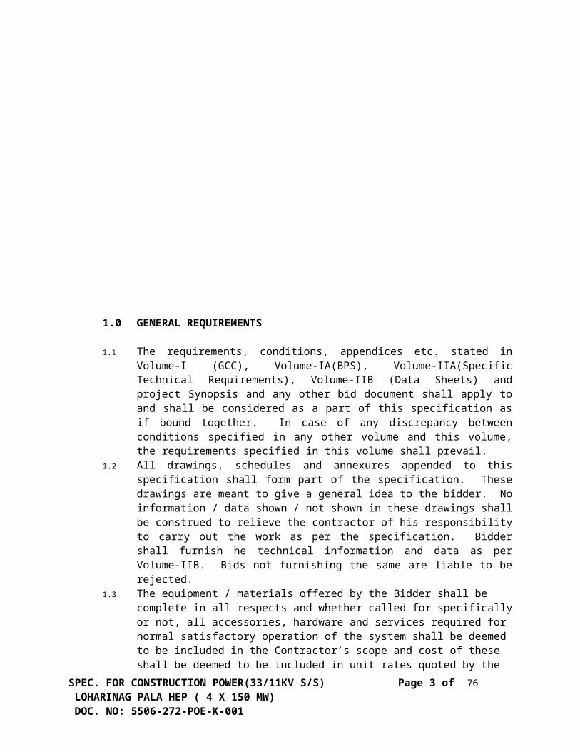
CONTENTS TITLE SHEET NO. 1.0 GENERAL REQUIREMENTS 3 2.0 CODES AND STANDARDS 4 3.0 GENERAL TECHNICAL REQUIREMENTS 6 3.1 EQUIPMENT DESCRIPTION 6 3.1.1 CIRCUIT BREAKERS (33 KV) 6 3.1.2 ISOLATORS (33 KV) 10 3.1.3 LIGHTING ARRESTERS (33 KV) 13 3.1.4 POWER TRANSFORMERS 15 3.1.5 INSTRUMENT TRANSFORMERS 25 3.1.6 D.C.SYSTEM 28 3.1.7 CONTROL AND RELAY PANEL 29 3.1.8 CABLES AND ACCESSORIES 32 3.1.9 11KV SWITCHGEAR 35 3.1.10 CLAMPS & CONNECTORS 40 3.1.11 BUSHINGS/ INSULATORS 42 3.1.12 MARSHALLING BOX 43 3.1.13 ILLUMINATION SYSTEM 44 3.1.14 EARTHING SYSTEM 44 3.1.15 FIRE FIGHTING EQUIPMENT 45 3.1.16 DANGER BOARDS 45 3.1.17 CABLE TRENCHES 45 3.1.18 AC DISTRIBUTION BOARD 45 3.2. WELDING 46 3.3 INSTALLATION 46 3.3.1 GENERAL INSTRUCTIONS FOR INSTALLATION 46 4.0 QUALITY ASSURANCE 46 SPEC. FOR CONSTRUCTION POWER(33/11KV S/S) Page 1 of 76 LOHARINAG PALA HEP ( 4 X 150 MW) DOC. NO: 5506-272-POE-K-001
Transcript of 33.11kv Substation for LNP
CONTENTS
TITLE SHEET NO.
1.0 GENERAL REQUIREMENTS3
2.0 CODES AND STANDARDS 43.0 GENERAL TECHNICAL
REQUIREMENTS6
3.1 EQUIPMENT DESCRIPTION 63.1.1 CIRCUIT BREAKERS (33 KV) 63.1.2 ISOLATORS (33 KV) 103.1.3 LIGHTING ARRESTERS (33 KV) 133.1.4 POWER TRANSFORMERS 153.1.5 INSTRUMENT TRANSFORMERS 253.1.6 D.C.SYSTEM 283.1.7 CONTROL AND RELAY PANEL 293.1.8 CABLES AND ACCESSORIES 323.1.9 11KV SWITCHGEAR 353.1.10 CLAMPS & CONNECTORS 403.1.11 BUSHINGS/ INSULATORS 423.1.12 MARSHALLING BOX 433.1.13 ILLUMINATION SYSTEM 443.1.14 EARTHING SYSTEM 443.1.15 FIRE FIGHTING EQUIPMENT 453.1.16 DANGER BOARDS 453.1.17 CABLE TRENCHES 453.1.18 AC DISTRIBUTION BOARD 453.2. WELDING 463.3 INSTALLATION 463.3.1 GENERAL INSTRUCTIONS FOR
INSTALLATION46
4.0 QUALITY ASSURANCE 465.0 TESTS 476.0 COMMISSIONING CHECKS 506.1 GENERAL 506.2 POWER TRANSFORMER 516.3 CIRCUIT BREAKER 516.4 ISOLATOR & EARTH SWITCH 52
SPEC. FOR CONSTRUCTION POWER(33/11KV S/S) Page 1 of 54 LOHARINAG PALA HEP ( 4 X 150 MW) DOC. NO: 5506-272-POE-K-001

6.5 CURRENT TRANSFORMERS 526.6 VOLTAGE TRANSFORERMS 526.7 CUBICLE WIRING 536.8 RELAYS 536.9 METERS 536.10 D.C.EQUIPMENT 536.11 CONTROL PANEL 547.0 LIST OF DRAWINGS 548.0 BILL OF MATERIAL(BOQ)
SPEC. FOR CONSTRUCTION POWER(33/11KV S/S) Page 2 of 54 LOHARINAG PALA HEP ( 4 X 150 MW) DOC. NO: 5506-272-POE-K-001
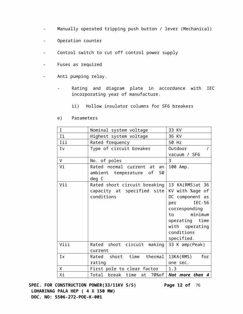
1.0 GENERAL REQUIREMENTS
1.1 The requirements, conditions, appendices etc. stated in Volume-I (GCC), Volume-IA(BPS), Volume-IIA(Specific Technical Requirements), Volume-IIB (Data Sheets) and project Synopsis and any other bid document shall apply to and shall be considered as a part of this specification as if bound together. In case of any discrepancy between conditions specified in any other volume and this volume, the requirements specified in this volume shall prevail.
1.2 All drawings, schedules and annexures appended to this specification shall form part of the specification. These drawings are meant to give a general idea to the bidder. No information / data shown / not shown in these drawings shall be construed to relieve the contractor of his responsibility to carry out the work as per the specification. Bidder shall furnish he technical information and data as per Volume-IIB. Bids not furnishing the same are liable to be rejected.
1.3 The equipment / materials offered by the Bidder shall be complete in all respects and whether called for specifically or not, all accessories, hardware and services required for normal satisfactory operation of the system shall be deemed to be included in the Contractor’s scope and cost of these shall be deemed to be included in unit rates quoted by the bidder. Also, design and manufacture shall be such that equipment / accessories of the same type and rating would be interchangeable.
1.4 Specific reference in this specification and documents to any material by trade name, make or catalogue number shall be construed as establishing standard of quality and performance and not as limiting competition. However, bidder may offer other similar equipment provide it meets the specified design and performance requirements. Also all equipment / accessories offered shall be proven design and manufacture.
1.5 The contractor shall have a separate cleaning gang to clean all equipment under erection as well as the work area of the project site at regular intervals to the satisfaction of the Engineer. In case the site cleaning is not to Engineer’s satisfaction, he will have the right to carry out the cleaning operations and expenditure incurred by the Engineer in this regard will be to the Contractor’s account.
1.6 The Contractor shall provide adequate and capable supervision for electrical installation work under this contract. The staff provided shall be adequate to provide detailed supervision at each stage of the work, in all areas, so that any improvements modifications required to meet site conditions / layouts is effected in time.
1.7 It is not the intent of the specification to specify completely herein all details of design and / or installation. However, the design, instruction and / or installation. However, the design, instruction and / or installation work shall conform, in all respects to the highest standard of engineering and workmanship and shall be capable of performing in continuos commercial operation upto the Contractor’sguarantee in a manner acceptable to the Engineer, who will be interpret the meaning of drawings and specification. The supply, installation, testing and commissioning shall be carried out in accordance with Owner’s instructions and this technical specification and / or applicable codes and standards including local statutory requirements. All work shall be executed to the satisfaction of the
SPEC. FOR CONSTRUCTION POWER(33/11KV S/S) Page 3 of 54 LOHARINAG PALA HEP ( 4 X 150 MW) DOC. NO: 5506-272-POE-K-001

Engineer. The engineer shall have the right to reject any equipment or work which in his judgement is not in full accordance therewith.
2.0 CODES AND STANDARDS
2.1 All standards, specifications and codes of practice referred to herein shall be the latest editions including all applicable official amendments and revisions as on data of opening of bid. In case of conflict between this specification and those (IS Codes, Standards, etc.) referred to herein, the former shall prevail. All work shall be carried out as per the following standards and codes.
IS : 5 Colours for ready mixed paints and enamels.
IS : 104 Ready mixed paint, brushing, zinc, Chrome, priming.
IS : 335 New insulating oils.
IS : 398 Part-II Aluminium conductors for overhead purposes.
IS : 731 Porcelain insulators for overhead lines (above 11 KV).
IS : 802 Code of practice for use of structural steel in overhead transmission lines.
IS : 1248 Electrical indicating instruments.
IS : 1271 Classification of insulating material for electrical machinery.
IS : 1554 PVC insulated heavy duty electrical cables.
IS : 1651 Stationary cells and batteries lead acid type (with tubular positive cells).
IS : 1652 Stationary cells and batteries lead acid type (with plante positive cells).
IS : 1866 Code of practice for electrical maintenance and supervision of mineral oil in equipment.
IS : 2026 Power transformers.
IS : 2099 Specification for bushings for a.c. voltages above 1000 V.
IS : 13947 Degree of protection provided by enclosure for switch gear control gear (Part-I, Part-II, Part-III).
IS : 2486 Insulator fittings for overhead power lines.
IS : 13118 Circuit breakers.
SPEC. FOR CONSTRUCTION POWER(33/11KV S/S) Page 4 of 54 LOHARINAG PALA HEP ( 4 X 150 MW) DOC. NO: 5506-272-POE-K-001

IS : 2544 Porcelain post insulators for above 1 KV.
IS : 2629 Recommended practice for hot dip galvanising of iron & steel.
IS : 2705 Current transformer
IS : 2932 Enamel, synthetic, exterior undercoating, finishing.
IS : 3043 Code of practice for earthing.
IS : 3070 Non linear type lightning arrestor.
IS : 3156 Voltage transformers.
IS : 3347 Dimensions of porcelain transformer bushings for use in normal and light polluted atmosphere.
IS : 3639 Fittings & accessories for power transformer.
IS : 3961 Recommended current rating for cables.
IS : 3975 Mild steel wires, strips and tapes for armouring of cables.
IS : 4004 Application guide for surge arresters.
IS : 4091 Code of practice for design and construction of foundations for transmission line towers & poles.
IS : 4146 Application guide for voltage transformers.
IS : 5350 Dimensions of indoor & outdoor porcelain post insulators for above 1 KV.
IS : 5613 Code of practice for design, installation and maintenance of overhead power lines.
IS : 5621 Specification for large hollow porcelains for use in electrical installation.
IS : 5831 PVC insulation & sheath of electric cables.
IS : 6600 Guide for loading of oil immersed transformers.
IS : 9921 AC disconnectors & earth switches for above 1000 volts.
IS : 10028 Selection, installation and maintenance of transformer.
IS : 10810 Cables – methods of test.
BS : 6121 Specification for cable glands.
SPEC. FOR CONSTRUCTION POWER(33/11KV S/S) Page 5 of 54 LOHARINAG PALA HEP ( 4 X 150 MW) DOC. NO: 5506-272-POE-K-001

IEC : 56 Circuit breaker.
- Indian Electricity Rules.
- Indian Electricity Act.
Indian Electricity Act and Indian Electricity Rules can be obtained from :-
Kitab MahalState Emporium ByuildingBaba Kharak Singh MargNew Delhi – 110 001.INDIA.
2.2 Equipment complying with other internationally accepted standards such as IEC, BS, USA, VDE etc. will also be considered if they ensure performance and constructional features equivalent or superior to standards listed above. In such a case, the Bidder shall clearly indicate the standard (s) adopted furnish a copy in English of the latest revision of the standards along with copies of all official amendments and revisions in force, as on date of opening of bid. Bidder shall clearly bring out the salient features for comparison.
3.0 GENERAL TECHNICAL REQUIREMENTS
3.1 Equipment Description
3.1.1 33 kV Circuit Breakers
a) Circuit breakers shall be outdoor vacuum/SF6 type, comprising three identical single pole units, complete in all respects with mechanically and operated through a common shaft by sturdy operating mechanism.
b) Duty Requirements
Circuit breaker shall be totally restrike free under all duty conditions and shall be capable of performing their duties without opening resistor. The circuit breaker shall meet the duty requirements of any type of fault and of fault location and shall be suitable for line charging and dropping when used on 33 KV effectively grounded or ungrounded systems and perform make and break operations as per the stipulated duty cycles satisfactorily. The circuit breaker shall be capable of :
i) Breaking the steady and transient magnetising current corresponding to 33 / 11 KV transformers upto 5 MVA rating.
ii) Breaking line charging currents as per IEC-56-2.
iii) Breaking inductive currents of 1 to 10 A without switching over voltage exceeding the limits specified in IEC.
SPEC. FOR CONSTRUCTION POWER(33/11KV S/S) Page 6 of 54 LOHARINAG PALA HEP ( 4 X 150 MW) DOC. NO: 5506-272-POE-K-001

c) Constructional Features
The features and constructional details of circuit breakers shall be in accordance with requirements stated here under :
i) All making and breaking contacts shall be sealed and free from atmospheric effects. In the event of leakage of extinguishing medium to a value which cannot withstand the dielectric stresses specified in the open position the contacts shall preferably self close. Main contacts shall be the first to open and the last to close so that there will be little contact burning and wear. Arcing contacts shall be the first to close and the last to open and shall be easily accessible for inspection and replacement. If there are no separately mounted arcing contacts, then the main contacts shall be easily accessible for inspection and replacement. Main contacts shall have ample area and contact pressure for carrying the rated current and the short time rated current of the breaker without excessive temperature rise which may cause pitting or welding. Contacts shall be adjustable to allow for wear, easily replaceable and shall have a minimum of movable parts. Tips of arcing and main contacts shall be silver plated or have a tungsten alloy tipping.
ii) The porcelain of the insulators shall conform to the requirements stipulated under Clause No.3.1.11. The puncture strength of the insulators shall be greater than the dry flash over voltage. The terminal connectors shall comply with the requirements of Clause – 3.1.10.
d) Operating Mechanism
i) Circuit breaker shall be operated by spring charged mechanism.
ii) The operating mechanism shall be anti-pumping and trip free (as per IEC definition) electrically and either mechanically under every method of closing (except during manual closing of a breaker for maintenance). A latch checking switch shall be provided on mechanically trip free mechanism to prevent reclosure before breaker latches have reset.
iii) The operating mechanism shall be such that the failure of any auxiliary spring will not prevent tripping and will not cause trip or closing operation of the power operated closing devices. A mechanical indicator shall be provided to so open and close positions of the breaker. It shall be located in a position where it will be visible to a man standing on the ground with the mechanism housing close. An operation counter shall also be provided.
iv) Closing coil shall operate correctly at all values of voltage between 85% and 110% of the rated voltage. Shunt trip shall operate correctly under all operating conditions of the circuit breaker up to the rated breaking capacity of the circuit breaker and at all values are supply voltage between 70% and 110% of rated voltage.
v) Working parts of the mechanism shall be corrosion resisting material. Bearings which required grease shall be equipped with pressure type grease fittings. Bearing pin, bolts, nuts and other parts shall be adequately pinned or locked to
SPEC. FOR CONSTRUCTION POWER(33/11KV S/S) Page 7 of 54 LOHARINAG PALA HEP ( 4 X 150 MW) DOC. NO: 5506-272-POE-K-001

prevent loosening or changing adjustment with repeated operation of the breakers.
vi) Operating mechanism shall normally be operated by remote electrical control . Electrical tripping shall be performed by shunt trip coil. Provisions shall be made for local electrical control. Local/Remote selector switches and close and push trip push buttons shall be provided in the breaker control cabinet. Remote located push buttons and indicating lamps shall also be provided by the contractor.
vii) A conveniently located mechanical tripping /liver or button shall also be provided for local tripping of the breaker. It shall be possible to trip breaker in the event of auxiliary supply failure.For spring charged mechanism a local manual closing device which can easily be operated by one man standing on the ground shall also be provided for maintenance purposes and direction of motion of handle shall be clearly marked.
viii) Spring operated mechanism shall be complete with motor, opening spring & closing spring with limit switch for automatic charging and other necessary accessories to make the mechanism a complete operating unit. As long as power is available to motor, a continuous sequence of closing and opening operations shall be possible.The motor shall have adequate thermal rating for this duty. After failure of power supply to motor , one open-close-open operation shall be possible. Breaker operation shall be independent of the motor which shall be used solely for compressing the closing spring. Motor rating shall be such that it requires not more than 30 seconds for fully charging the closing spring .Closing action of the circuit breaker shall compress the opening spring ready for tripping. When closing spring s are discharged, after closing of the breaker, closing springs shall automatically be charged for the next operation and an indication of this shall be provided in the local control cabinet.
ix) Motor shall be suitable for 415V, 3-phase power supply .Motor shall be squirrel cage induction type, totally enclosed, fan cooled, class-B insulated, suitable for tropical climate conforming to IS:325.
e) Fittings and Accessories
Following is partial list of some of the major fitting and accessories to be furnished by the contractor as an integral parts of the equipment. Number and exact location of these parts shall be indicated in the bid.
i) Marshalling box in accordance with clause No.3.1.12 complete with
- Cable glands
- Local / remote change over switch
- Manually operated tripping push button / lever (Mechanical)
- Operation counter
SPEC. FOR CONSTRUCTION POWER(33/11KV S/S) Page 8 of 54 LOHARINAG PALA HEP ( 4 X 150 MW) DOC. NO: 5506-272-POE-K-001

- Control switch to cut off control power supply
- Fuses as required
- Anti pumping relay.
- Rating and diagram plate in accordance with IEC incorporating year of manufacture.
ii) Hollow insulator columns for SF6 breakers
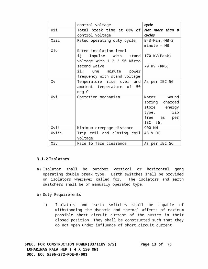
e) Parameters I Nominal system voltage 33 KVIi Highest system voltage 36 KVIii Rated frequency 50 HzIv Type of circuit breaker Outdoor / vacuum /
SF6V No. of poles 3Vi Rated normal current at an ambient
temperature of 50 deg C100 Amp.
Vii Rated short circuit breaking capacity at specified site conditions
13 KA(RMS)at 36 KV with %age of DC component as per IEC-56 corresponding to minimum operating time with operating conditions specified.
Viii Rated short circuit making current 33 K amp(Peak)Ix Rated short time thermal rating 13KA(RMS) for one
sec.X First pole to clear factor 1.3Xi Total break time at 70%of control
voltage Not more than 4 cycle
Xii Total break time at 80% of control voltage
Not more than 8 cycles
Xiii Rated operating duty cycle B-3-Min.-MB-3 minute – MB
Xiv Rated insulation leveli) Impulse with stand voltage with 1.2 / 50 Micro second waive ii) One minute power frequency with stand voltage
170 KV(Peak)
70 KV (RMS)
Xv Temperature rise over and ambient temperature of 50 deg.C
As per IEC 56
Xvi Operation mechanism Motor wound spring charged store energy type. Trip free as per IEC- 56.
SPEC. FOR CONSTRUCTION POWER(33/11KV S/S) Page 9 of 54 LOHARINAG PALA HEP ( 4 X 150 MW) DOC. NO: 5506-272-POE-K-001

Xvii Minimum creepage distance 900 MMXviii Trip coil and closing coil voltage 48 V DCXiv Face to face clearance As per IEC 56
3.1.2 Isolators
a) Isolator shall be outdoor vertical or horizontal gang operating double break type. Earth switches shall be provided on isolators wherever called for. The isolators and earth switchers shall be of manually operated type.
b) Duty Requirements
i) Isolators and earth switches shall be capable of withstanding the dynamic and thermal affects of maximum possible short circuit current of the system in their closed position. They shall be constructed such that they do not open under influence of short circuit current.
ii) In addition to the constructional inter lock; isolators and earth switches shall have provision to prevent their operation unless the associated and other interlocking conditions are met. All these interlocks shall be of fail safe type.
iii) The earthing situation shall have an assigned making current rating as stipulated in IS : 9921.
iv) The isolator shall be capable of making / breaking magnetizing current of 0.7 A at 0.15 power factor and capacity current of 0.7 A at 0.15 power factor.
v) Isolator and earth switches shall be able to bear on the terminals the total force including wind loading and electro dynamic forces on the attached conductor without impairing reliability or current carrying capacity.
vi) The isolator shall be capable of making / breaking normal currents when no significant change in voltage occurs across the terminals of each role of the isolators on account of making / breaking operation.
c) Constructional features
The features and construction details of isolators, earth switches and accessories shall be in accordance with requirements stated hereunder :
i) Isolators shall be provided the high pressure current carrying contacts on the hinge / jaw bends and all contact surfaces shall be silver plated. The contracts shall be accurately machined and self aligned.
ii) Each single pole of the isolators shall be provided with a complete galvanized steel based provided with poles and designed for mounting on a security structure to be provided with holes and designed for mounting on a
Supporting structure to be provided by the contractor. The base shall be rigid and self supporting. The position of moveable contact system (Main blades)
SPEC. FOR CONSTRUCTION POWER(33/11KV S/S) Page 10 of 54 LOHARINAG PALA HEP ( 4 X 150 MW) DOC. NO: 5506-272-POE-K-001

of each of the isolators and earthing switches shall be indicated by a mechanical indicator at the lower end of the vertical rod of shaft for the isolator and earthing switch. The indicator shall be of metal and shall be visible from operating level.
iii) All metal parts shall be of non-rusting and non-corroding metal. Current carrying parts shall be of non-ferrous materials. Bolts, screws and pins shall be provided with lock washers. Keys or equivalent locking facilities if on current carrying parts, shall be made of copper silicon alloy or equivalent. The bolts or pins used in current carrying parts shall be made of non-ferrous and non-corroding material. The live parts shall be designed to eliminate sharp joints, edges and other corona producing surfaces. The isolators shall be so constructed that the switch blade will not fall to the closed position if the operating shaft gets disconnected. Isolators and earthing switches including their operating parts shall be such that they cannot be dislodged from their open or closed positions by gravity, wind pressure, vibrators shocks or accidental touching of the connecting rods of the operating mechanism. The switch shall be designed such that no lubrication or any part is required 3zxcept at very infrequent intervals.
iv) The porcelain of the insulator shall conform to the requirements stipulated under Clause No.3.1.11 and shall have a minimum cantilever strength of 800 Kg. Pressure due to the contact shall not be transferred to the insulators after the main blades full close. The insulators shall be so arranged that leakage current will pass to earth and not between terminals of the same pole or between phases. All equipment shall be supplied with terminal connectors suitable for ACSR conductor intended for connection and shall be capable of withstanding the normal and short circuit currents.
d. Earthing Switches
Where earthing switches are specified these shall include the complete operating mechanism and auxiliary contacts. The earthing switches shall form an integral part of the isolator. Earthing switches shall be suitable for local manual operation only. The earthing switches shall be constructionally inter lock with the isolator so that the earthing switches can be operated only when the isolator is open and vice-a-versa. Each earth switch shall be provided with flexible copper braids for connection to ground met. These braids shall have the same making capacity as the earth blades. The plane of movement and final position of the earth blades shall be such that adequate electrical clearances are obtained from adjacent live parts. The frame of each isolators and earthing switches shall be provided with two reliable earth terminals for connection to the earth met. The earth switch should be able to carry the same fault current as the main blades of isolators and shall withstand dynamic stresses.
e. Operating Mechanism and Control
The design shall be such that minimum energy is required for operation and one man shall be able to operate the isolators without undue effect. The height of the operating handle above ground level shall be approximately 1300 mm. Isolator shall have gang operating drive for main blades and earth switch. The three
SPEC. FOR CONSTRUCTION POWER(33/11KV S/S) Page 11 of 54 LOHARINAG PALA HEP ( 4 X 150 MW) DOC. NO: 5506-272-POE-K-001
poles shall be well synchronized and interlocked. The isolator shall be provided with positive continuous control throughout the entire cycle of operation. The operating pipes and rods shall be sufficiently rigid to maintain positive control under the most adverse conditions and when operated in tension or compression for isolator closing. They shall also be capable of withstanding all torsional and bending stresses due to operation of the isolator. It shall not be possible, after final adjustment has been made, for any part of the mechanism to be displaced at any point in the travel sufficient enough to allow improper functioning of the isolator when the isolator is opened or closed at any speed. All holes in cranks, linkages etc. having moving pins shall be drilled to accurate fit so as to maintain the minimum amount of slack and lost motion in the entire mechanism. All isolators and switches shall be provided with operating handles with pad locking arrangements. All brackets angles or other members necessary for the attaching the operating mechanism to the isolators supporting structure shall be supplied as an integral part of the isolators. Rust proof pins and bearings of the bronze bushing ball or roller type shall be furnished. Castle key interlock shall be provided to ensure isolator operation only when associated circuit breaker is open.
f. Parameters
i. Nominal system voltage : 33 KV
ii. Highest system voltage : 36 KV
iii. System frequency : 50 Hz
iv. Type : Outdoor / manually operated
v. Rated current at 50 deg.C : 100 Aambient temperature `
vi. Rates short time withstand Current of isolator and earth switch : 13 KA (rms for 1 sec.)
vii. Rated insulation levelsImpulse withstand voltage with 1.2 / 50 micro sec. Wave : 170 KV (Peak)
One minute power frequency Withstand voltage : 70 KV (rms)
The parameters shall also conform to IEC129 and IEC 694.
viii. Temperature rise : As per Table-IV of IS : 9921-II/IEC-694 for an ambient temperature of 50 deg.C
ix. Rated mechanical terminal load : As per table – VII of IEC-129 (1975)
x. Operating mechanism of isolator : Manually operated
SPEC. FOR CONSTRUCTION POWER(33/11KV S/S) Page 12 of 54 LOHARINAG PALA HEP ( 4 X 150 MW) DOC. NO: 5506-272-POE-K-001
xii Creepage distance(Total) : 900 mm.
3.1.3 Lightning Arrester
GENERAL
The arresters (LAs) shall conform in general to IEC 99.4 or IS:3070 except to the extent modified in the specification
Arresters shall be of hermetically sealed units, self supporting construction, suitable for mounting on Lattice type support structures.
DUTY REQUIREMENTS
The LAs shall be of heavy duty station class and gapless Metal Oxide type without any series or shunt gaps.
The LAs shall be capable of discharging lightening over voltage and over-voltages occurring during switching of unloaded transformers, and long lines.
The reference current of the arresters shall be high enough to eliminate the influence of grading and stray capacitance on the measured reference voltage.
The duty cycle of circuit breaker installed in the system shall be 0-3 min.CO-3 min-CO. The LA shall be suitable for such circuit breaker duties in the system.
The surge arresters shall be capable of withstanding meteorological and short circuit forces when installed in layout arrangement as described in the specification.
Lighting arresters shall be capable of discharging severe re-energisation switching surges on 33kV lines upto 50 km. length.
Lighting arrester shall be capable of discharging energy equivalent to class-3 of IEC of a 33kV system of two successive operations.
CONSTRUCTIONAL FEATURES
The non-linear blocks shall be of sintered metal oxide material. These shall be provided in such a way as to obtain robust construction, with excellent stable mechanical and electrical properties even after repeated operations.
The surge arresters shall be fitted with pressure relief devices and are diverting ports suitable for preventing shattering of porcelain housing.
The arresters shall not fail due to Arrester porcelain contamination.
SPEC. FOR CONSTRUCTION POWER(33/11KV S/S) Page 13 of 54 LOHARINAG PALA HEP ( 4 X 150 MW) DOC. NO: 5506-272-POE-K-001
Seals shall be provided in such a way that these are always effectively maintained even when discharging rated lightning current.
Outer insulator shall be porcelain conforming to requirements of Cl. 3.1.10.
Porcelain housing shall be so co-ordinated that external flashover will not occur due to application of any impulse or switching surge voltage upto the maximum design value for arrester.
The end fittings shall be made of non-magnetic and corrosion proof material.
The base of the LA shall be provided with two separate terminals distinctly marked for connection to earth.
FITTINGS AND ACCESSORIES
Arrestors shall be complete with insulating base having provision for bolting to flat surface of structure.
Self contained discharge counters, suitably enclosed for outdoor use and requiring no auxiliary or battery supply for operation shall be provided for each single pole unit alongwith necessary connection. Suitable leakage current meters should also be supplied within the same enclosure. The reading of millimeter and counters shall be visible through analysis inspection glass panel. A pressure relief device vent / other suitable provision shall be made so as to prevent excessive pressure build up / shattering of view glass. The terminals shall be robust and of adequate size and shall be so located that the incoming and outgoing connections are made with the minimum possible bends. The design of the discharge counters shall be such that the readings are visible clearly to a person standing at ground level.
Discharge counters and millimeters should be suitably mounted on support structure of the arrester and type tested for IP-55 degree of protection.
Grading/ corona rings shall be provided in each complete arrester unit as required.
PARAMETERS
a) Rated system voltage 33 kV
b) Rated arrester voltage 30 kV
c) Nominal discharge current10 kA of 8/20 micro-sec wave
d) Minimum discharge capability 5 kJ/kV (referred to rated arrester voltage corresponding to min. discharge characteristics)
SPEC. FOR CONSTRUCTION POWER(33/11KV S/S) Page 14 of 54 LOHARINAG PALA HEP ( 4 X 150 MW) DOC. NO: 5506-272-POE-K-001
e) Maximum continuous operating 24 kV rmsvoltage at 50 deg C.
f) Max. residual voltage (1 kA) 70 kVp
g) Max. residual voltage at 85 kVp10kA nominal discharge currentmicro-sec wave)
h) Max. switching impulse residual 70 kVpVoltage at 500A peak
i) Max. steep current residual voltage 93 kVpAt 10kA
j) Long duration discharge class 3
k) High current short duration test 100 kApValue (4/10 micro-sec wave)
l) Current for pressure relief test 25 kA rms
m)Low current long duration test As per IECValue (2000 micro-sec)
n) Prospective symmetrical fault current 25kA for 1 sec.
o) Pressure relief class as per IEC 99 A
p) Insulation withstand voltage(i) Dry & wet power frequency 70 kV rms (ii) Lightning impulse 170 kVp
3.1.4 Power Transformers
The features and constructional details of all transformers shall be in accordance with the requirements stated herein under :
a. Tanks & Tank Accessories
i. Tank shall be of welded construction, fabricated from tested quality low carbon steel of adequate thickness. All seams and those joints not required to be opened at site shall be factory welded and wherever possible they shall be double welded. All welding shall preferably be stress relieved. Tank stiffeners shall be provided for general rigidity and these shall be designed to prevent retention of water. The tanks shall be designed to withstand :
- Mechanical shocks during transportation.
SPEC. FOR CONSTRUCTION POWER(33/11KV S/S) Page 15 of 54 LOHARINAG PALA HEP ( 4 X 150 MW) DOC. NO: 5506-272-POE-K-001

- Vacuum filling of oil
- Short circuit force.
ii. Wherever possible the transformer tank and its accessories shall be designed without pockets wherein gas may collect. Where pockets cannot be avoided pipes shall be provided to vent the gas into the main expansion pipe. Suitable guides shall be provided in the tank for positioning the core and coil assembly. Adequate space shall be provided at the bottom of the tank for collection of sediment.
iii. Each tank shall be provided with :
- Lifting lugs suitable for lifting the complete transformer.
- A minimum of four jacking pads, in accessible positions to enable thetransformer complete with oil to be raised or lowered using hydraulic orscrew jacks.
- Suitable haulage holes for transformer wheeling in all four directions.
- Two earthing pads suitable for bolted connection of 50 x 8 mm.galvanised mild steel flat at positions closed to the two diagonallyopposite bottom corners of tank. The earthing terminal shall be capableof carrying for 4 secs. the full lower voltage short circuit current oftransformer.
iv. Suitable bi-directional skids with predrilled holes shall be provided integral
with the tank body for fixing the transformer tank on foundation. These skids shall be such that the bottom of the tank body is at a sufficientheight above foundations for cleaning purposes.
b. Tank Cover
The tank cover shall be sloped to prevent retention of rain water and shall not distort when lifted. At least two adequately sized inspection openings one at each end of the tank shall be provided for easy access to bushings and earth connections. The inspection covers shall not weigh more than 25 Kgs. and shall have suitable lifting arrangement. The tank covers shall be fitted with thermometer pockets (in the position of maximum oil temperature at MCR) for bulbs of oil and winding temperature indicators. It shall be possible to remove these bulbs without lowering the oil in the tank. Bushings, turrets, covers of inspection openings, thermometer pockets. etc. shall be designed to prevent ingress of water into or leakage of oil from the tank. Turrets and other part surrounding the conductors of only one phase shall be non-magnetic. All bolted connections shall be fitted with weather proof, hot oil resistant neoprene gasket in between for complete oil tightness. If gasket is compressible, metallic stops shall be provided to prevent over compression.
C. Axle and Wheels
SPEC. FOR CONSTRUCTION POWER(33/11KV S/S) Page 16 of 54 LOHARINAG PALA HEP ( 4 X 150 MW) DOC. NO: 5506-272-POE-K-001
The transformers shall be provided with flanged bi directional wheels and axles. These shall be so designed that under both the directions of movement they shall not deflect sufficiently to interfere with movement of the transformer. Wheels shall be provided with suitable bearings which shall be rust and corrosion resistant. Fittings for lubrication shall also be provided. Suitable locking arrangement shall be provided for the wheels to prevent accidental movement of transformers. The wheels are required to swivel and they shall be arranged so that they can be turned through an angle of 90 deg. when the tank is jacked up clear of the rails, Means shall be provided for locking the swivel movement in position parallel to and at right angles to the longitudinal axis of the tank. The rail track gauge shall be 5’ – 6” (167 mm.) along longer axis as well as a long shorter axis.
d. Anti Earthquake Clamping Device
To prevent transformer movement during earthquake, a clamping device should be provided for fixing the transformer to the foundation. The contractor shall supply necessary bolts for embedding in the concrete. The arrangement shall be such that the transformer can be fixed to or unfastened from these bolts as desired.
e. Oil Preservation System
The transformer shall be provided with conventional single compartment conservator with dry air filling the space above the oil. The top of the conservator shall be connected to the atmosphere through a silicagel breather. The Buchholz relay shall also be provided as specified.
f. Conservator tank:The conservator tank shall have adequate capacity to accommodate oil preservation system and volumetric expansion of total transformer oil for a change in temperature from minimum ambient to 100 deg.C. The conservator shall be bolted into position so that it can be removed for cleaning purposes. It shall not obstruct with other connections to the transformer. Each conservator vessel shall be fitted with a silica gel filter breather. Breather shall be mounted at about 1400 mm. Above rail top level / floor level. It shall be so designed that :
Passage of air is through a dust filter and silicagel. Silicagel is isolated from atmosphere by an oil seal.
Moisture absorption is indicated by a change in colour of the crystals and easily observed from a distance.
g. Pressure Relief Device
The pressure relief device provided shall be of sufficient size for rapid release of any pressure that may be generated within the tank and which may result in damage to the equipment. The device shall operate at a static pressure, which shall be less than the hydraulic test pressure of transformer tank. Diaphragm type explosion vent shall be provided. Means shall be provided to prevent
SPEC. FOR CONSTRUCTION POWER(33/11KV S/S) Page 17 of 54 LOHARINAG PALA HEP ( 4 X 150 MW) DOC. NO: 5506-272-POE-K-001
ingress of rain water. An equalizer pipe shall be connected to explosion vent from the conservator.
h. Buchholz Relay
A double float type Buchholz relay conforming to IS : 3637 shall be provided. All gas evolved in the transformer shall collect in this relay. The relay shall be provided with a test cock suitable for a flexible pipe connection for checking its operation. A copper tube shall be connected from the gas collector to a valve located about 1200 mm. above ground level to facilitate sampling with the transformer in service. The device shall be provided with two electrically independent ungrounded contacts, one for alarm on gas accumulation and the other for tripping on sudden rise of pressure.
i. Temperature Indicator
i) Oil Temperature Indicator (OTI)
All transformers shall be provided with a 150 mm dial type thermometer for top oil temperature indication. The transformer shall have adjustable, electrically independent ungrounded alarm and tip contacts, maximum reading pointer and resetting device and shall be mounted in the marshalling box. A temperature sensing elements suitably located in a pocket in top oil shall be furnished. This shall be connected to OTI by means of capillary tubing. Accuracy class of OTI shall be + 2 deg. C or better.
ii) Winding temperature indicator
A device for measuring the hot spot temperature of the winding shall be provided. The accuracy class of winding temperature indicator shall be + 2 deg. C or better. It shall comprise temperature sensing element, image coil and bushing current transformer, aux. CTs, if required to match the image coil, automatic ambient temperature compensation and 150 mm local indicating instrument with maximum reading pointer mounted in marshalling box. The device shall have two adjustable electrically independent, ungrounded alarm and trip contacts. All contacts shall be adjustable on a scale and suitable for connection in 48v DC (min) circuit. These shall be accessible on removal of the cover.
j. Core
The core shall be constructed from high grade non ageing, cold rolled grain oriented silicon steel laminations. The design of the magnetic circuit shall be such as to avoid static discharges, development of short circuit paths within itself or to the earthed clamping structure and the production of flux component at right angles to the plane of laminations, which may cause local heating. The insulation of core of bolts and core to clamp plates shall be able to withstand a voltage of 2 KV RMS 50 Hz for one minute Core and windings shall be capable of withstanding shocks during transport, installation, service and adequate provision shall be made to prevent movement of core and winding relative to tank during these conditions. All steel sections used for supporting the core
SPEC. FOR CONSTRUCTION POWER(33/11KV S/S) Page 18 of 54 LOHARINAG PALA HEP ( 4 X 150 MW) DOC. NO: 5506-272-POE-K-001

shall be thoroughly sand blasted after cutting drilling and welding. Eye and lugs shall be provided for lifting the core.
k. Windings
The conductors shall be of electrolytic grade copper. All windings of all the transformers shall be fully insulated. The insulation of transformer windings and connections shall be free from insulating compounds which are liable to soften, ooze-out, shrink or collapse and be non-catalytic & chemically inert in transformer oil during service. Coil assembly and insulating spacers shall be so arranged as to ensure free circulation of oil and to reduce the hot spots of the windings. Tapping shall be so arranged as to preserve the magnetic balance of transformers at all voltage ratios. The fault levels of the various systems to which these transformer would be connected are indicated under parameters. Transformer manufacturer may take this aspect into account while designing the transformer for the through fault withstands capability for three (3) seconds. The contractor shall give supporting calculations for the same.
l. Off Circuit Tap change switch
The tap change switch shall be three phase, hand operated for simultaneous, switching of similar taps on the three phases by operating an external handwheel. Tap changing shall be possible without disturbing the transformer in any way except de-energizing. Arrangement shall be made for securing and pad-locking the tap changer in any of the working positions and it shall not be possible for setting or padlocking it in any intermediate positions. An indicating device shall be provided to show the tap in use. The cranking device for manual operation of the off circuit tap changing gear shall be removable and suitable for operation by a man standing on ground level. The mechanism shall be complete with the following:
i) Mechanical tap position indicator which shall be clearly visible from nearby transformer.
ii) A mechanical operation counter.
iii) Mechanical stops to prevent over cranking of the mechanism beyond the extreme tap position.
iv) The manual operating mechanism labeled to show the direction of operation for raising the secondary voltage and vice-versa.
v) A warning plate fitted indicating. “The switch shall be operated only when the transformer has been de-energised”.
m.Radiators
SPEC. FOR CONSTRUCTION POWER(33/11KV S/S) Page 19 of 54 LOHARINAG PALA HEP ( 4 X 150 MW) DOC. NO: 5506-272-POE-K-001

The radiators shall be detachable type, mounted on the tank with shut off valve at each point of connection to the tank, along with drain valve at the bottom and relief valve at the top.
n. Insulating Oil
i. The new insulating oil before pouring into the transformer shall conform to the requirement of IS : 335. No inhibitors shall be used in the oil. The oil samples taken from the transformer at site shall conform to the requirements of IS : 1866 and the values for various parameters shall not lie very close to the limiting values specified in IS : 1866 with respect to the reconditioning.
ii. The Contractor shall despatch the transformer filled with oil or nitrogen. In the former case, the Contractor shall take care of the weight limitation on transport and handling facility at site. In the latter case, necessary arrangement shall be ensured by the Contractor to take care of pressure drop of nitrogen during transit and storage till completion of oil filling during erection. A gas pressure-testing valve with necessary pressure gauge and adopter valve shall be provided. In such case, sufficient quantity of oil required for first filling of tank, coolers and radiators at the proper level shall be supplied. Ten percent (10%) extra oil shall be supplied for topping up, in non-returnable containers suitable for outdoor storage.
o. Terminal Arrangement
i. The electrical characteristics of bushings shall be in accordance with IS: 2099 & IS : 3347 (relevant parts). Bushing terminals shall be provided with terminal connectors of approved type and size for connection to external parts. Bushings shall be of solid porcelain or oil communicating type. Bushing removal shall be possible without disturbing the current transformers secondary terminals and connections or pipe work. The neutral terminal of 11 KV winding shall be brought out on a separate bushing and shall be solidly earthed. Earthing strip from neutral bushing to the earth is to be insulated from the tank body and brought down to a suitable height to connect to earth.
i) The terminal marking and their physical position shall be in accordance with IS : 2026 unless specified otherwise.
p) A sheet steel, weather, vermin and dust proof marshalling box shall be furnished with each transformer to accommodate temperature indicators & terminal boards for incoming and outgoing cables. Marshalling box shall conform to the requirements of Clause 3.1.11. The temperature indicators shall be so mounted that the dials are not more than 1600 mm, from ground level. The marshalling box shall have a door with a cut out fitted with glass window of suitable size for convenience of temperature indicators reading.
q Painting
i)The internal and external surfaces including oil filled chambers and structure steel work to be painted shall be hot or sand blasted to remove all rust and scale
SPEC. FOR CONSTRUCTION POWER(33/11KV S/S) Page 20 of 54 LOHARINAG PALA HEP ( 4 X 150 MW) DOC. NO: 5506-272-POE-K-001

or foreign adhering matter. All steel surfaces in contact with insulating oil shall be painted with two coats of heat resistant, oil insoluble, insulating varnish.ii)All steel surfaces exposed to weather shall be given a primary coat of zinc chromate, second coat of oil and weather resistant varnish of a colour distinct from primary, and final two coats of glossy oil and weather resisting non fading paint, the shade of which shall be 631 as per IS : 5. Primary paint shall be as per IS : 104 and intermediate and final coats of paint shall be as per IS : 2932. All paints shall be carefully selected to withstand heat and extremes of weather. The paint shall not scale off or wrinkle or be removed by abrasion due to normal handling.
iii)Nuts, bolts and washers which may have to be removed for maintenance purposes shall have a minimum of one coat of paint after erection. Any damage to paint during transport or erection shall be made good by the contractor. One coat of additional paint shall be given at the site by the contractor.
r. Bolts and Nuts
All bolts and nuts exposed to weather shall be of galvanised steel or cadmium plated steel.
s. Control Wiring
i)All controls, alarms, indicating and relaying devices provided with the transformer shall be wired upto the terminal blocks inside the marshalling box. The contractor shall supply and install the required 1100 V grade heavy duty PVC insulated, armoured, PVC sheathed multicore cables with copper conductors of at least 2.5 sq.mm. conforming to IS : 1554. The cables shall be properly supported.
ii)All devices and terminal blocks within the marshalling Box shall be clearly identified by symbols corresponding to those used on applicable schematic or wiring diagrams.
iii)Not more than two wires shall be connected to one terminal. At least 20% spare terminals shall be provided. Each terminal shall be suitable for connecting two 2.5 sq.mm. standard copper conductors from each side. Terminal connector for control cable shall be of ESSEN make or equivalent. Terminal blocks for CT secondary shall have shorting facility.
t Fitting
The following fittings shall be provided with all the transformers, unless mentioned specifically otherwise.
i. Conservator with oil filling hole and cap, isolating valve, drain valve, vent valve.
ii. Magnetic oil level gauge with low level alarm contacts mounted on conservator.
SPEC. FOR CONSTRUCTION POWER(33/11KV S/S) Page 21 of 54 LOHARINAG PALA HEP ( 4 X 150 MW) DOC. NO: 5506-272-POE-K-001

iii. Dehydrating filter breather for conservator.
iv. Prismatic / toughened glass oil level gauge for transformer.
v. Oil preservation system as specified.
vi. Buchholz relay, double float type with isolating valve bleeding pipe and alarm and trip contacts.
vii. Pressure relief device.
viii. Air release plugs.
ix. Inspection opening and covers.
x. Bushing with metal parts and gaskets to suit the termination arrangement.
xi. Oil temperature indicator with alarm and trip contact.
xii. Winding temperature indicator with alarm and trip contact
xiii. Cover lifting eyes, transformer lifting lugs, jacking pads, towing holes core and winding lifting lugs, supporting structure, foundation bolts etc.
xiv. Protected type mercury or alcohol in glass thermometer.
xv. Bottom and top filter valves with threaded male adopters, bottom sampling valve and drain valve.
xvi. Rating and diagram plates.
xvii. Flanged bi-directional wheels for the transformer.
xviii. Off load tap changing equipment for transformer.
xix. Marshalling box along with necessary fittings..
xx. Earthing terminals.
The fittings listed above are only indicative and any other fittings which are generally required for satisfactory operation of the transformers are deemed to be included.
u. Performance
i. Transformers shall be capable of being loaded in accordance with IS : 6600 upto 150%. There shall be no limitation imposed by bushings, tap changer etc. The transformer shall be capable of being operated
SPEC. FOR CONSTRUCTION POWER(33/11KV S/S) Page 22 of 54 LOHARINAG PALA HEP ( 4 X 150 MW) DOC. NO: 5506-272-POE-K-001

continuously without danger on any tapping at the rated KVA with voltage variation of + 10% corresponding to the voltage of the tapping.
ii). The transformer and all accessories including CTs etc. shall be capable of withstanding for three seconds any external short circuit at bushing terminal without any damage. The maximum flux density in any part of the cores and yoke at normal voltage and frequency shall be such that the flux density on any tap position with + 10% voltage variation from voltage corresponding to the tap shall not exceed 1.9 wb/m2. Transformers shall accept, without injurious heating, combined voltage and frequency fluctuations which produce the over fluxing conditions of 120% for 1 minute. The bidder shall indicate 150% over voltage withstand time.
iii) The noise level when energized at normal voltage and frequency shall not exceed, when measured under standard conditions the values specified in NEMA TR-1.
iii) Technical Parameters
Sl no.
DESCRIPTION HT 33/11.5 KV TRANSFORMERS
i. No.of transformers 2 Nos.
Ii Rated output 5 MVA
Iii Cooling ONAN
Iv Type Two winding, oil immersed
V Voltage ratio 33/11.5 KV
Vi Frequency 50 HzVii Phase Three
Viii Service Outdoor
Ix Duty Continuous
X Overload capacity As per IS : 6600 & as specified elsewhere in the specification.
Xi Temperature rise
Winding (by resistance method) Top oil (By termometer )
55 deg.C
50 deg.C
Xii P.U.Impedance at 75 deg.C & permissible tolerance
As per IS : 2026( 7.15%)
Xiii Fault level of the 21 KA on 33 KV sideSPEC. FOR CONSTRUCTION POWER(33/11KV S/S) Page 23 of 54 LOHARINAG PALA HEP ( 4 X 150 MW) DOC. NO: 5506-272-POE-K-001
system Xiv Vector group DynlXv Windings
Winding connection
HV LV
Delta Star
HV LVHighest system voltage (KV)
36 12
One minute power frequency withstand voltage (KV)(rms)
70 28
Lighting impulse withstand voltage (KV)peak
170 70
Insulation Uniform Uniform
Neutral - Solidly Grounded
Xvi Tap changer Off circuit tap change switch on HV winding with range of +5% in steps of 2.5%
Xvii Phase Bushings HV LVRated voltage (KV) 36 12Rated current (A) 100A 400A
Basic impulse level (KV)peak
170 70
Minimum creepage distance (mm)
900 300
Mounting Tank cover or Tank side Quantity 3 3
SPEC. FOR CONSTRUCTION POWER(33/11KV S/S) Page 24 of 54 LOHARINAG PALA HEP ( 4 X 150 MW) DOC. NO: 5506-272-POE-K-001
Xviii Neutral Bushing with CTs Rated voltage (KV)
Rated Current(Amp.)
Basic impulse level (KV)peakMinimum creepage distance (mm)Mounting
Quantity
LV Neutral
12
250
70
300 mmTank cover or tank side with approval of Owner
One
Bushing current transformer
No. of cores
Service and class
Ratio
Rated burden
On LV Neutral
Two
5 P 20, PS
50/1 400/1
10VA 10VA
Xix Termination Details
HV phases
LV Phase
LV Neutral
Overhead conductor “ACSR Raccoon”
Cable (1Cx400 sq. mm 11/6.35 grade XLPE)
Copper flats connections
3.1.5 Instrument Transformers
a. Constructional Features
The features and constructional details of instrument transformers shall be in accordance with requirements stipulated hereunder:
SPEC. FOR CONSTRUCTION POWER(33/11KV S/S) Page 25 of 54 LOHARINAG PALA HEP ( 4 X 150 MW) DOC. NO: 5506-272-POE-K-001

i. Instrument transformers shall be mounted in 36 KV class, oil filled shedded porcelain bushings suitable for outdoor service and upright mounting on steel structures. Bushings and terminal connectors shall conform to Clause No 3.1.11. and 3.1.10 Bushings shall be provided with lifting arrangements, oil filling and drain plugs, oil sight glass etc. Instrument transformers shall preferably be hermetically sealed units with in-built provision to dissipate any excessive pressure built up. In lieu adequate pressure relief device shall be provided.
ii. Marshalling box shall conform to the requirements of Clause 3.1.12. Polarity marks shall indelibly be marked on each instrument transformer and at the lead terminations at the associated terminal block.
iii. Instrument transformers shall be supplied complete with insulating oil conforming to IS : 335, required for first filling. In case instrument transformers are not of hermetically sealed ltype, 10% extra oil shall be supplied in sealed non-returnable drums for topping up.
b.) Current Transformers
i. Current transformers shall be of ring type with suitable connections at the bottom for bringing our secondary terminals in a weatherproof terminal box. Different ratios specified shall be achieved by secondary taps. Facilities shall be provided at the terminal blocks in the control cabinets for Star-Delta formation, short circuiting and grounding of CT secondary terminals.
ii. Core lamination shall be of cold rolled grain oriented silicon steel or other equivalent alloy. The cores used for protection should be of low reactance type and shall produce undistorted secondary current under transient conditions at all the ratios. All current transformers shall be provided with two terminals studs per pole.
iii. Current transformer characteristics shall be such as to provide satisfactory performance for burdens ranging from 25% to 100% of rated burden over a range of 10% to 100% of rated current in case of metering CTs and upto the accuracy limit factor in case of relaying CTs. Current transformer guaranteed burdens and accuracy class are to be intended as simultaneous for all cores. The rated extended primary current shall be 120% of the rated primary current. The current transformer shall preferably be suitable for horizontal transportation.
c. Voltage Transformers
Voltage transformers primary and secondary shall have fuses. These fuses shall be located in the individual phase terminal boxes.
d. Current Transformers Parameters
SPEC. FOR CONSTRUCTION POWER(33/11KV S/S) Page 26 of 54 LOHARINAG PALA HEP ( 4 X 150 MW) DOC. NO: 5506-272-POE-K-001

I Highest system voltage 36 KVIi Rated primary current 100A Iii Rated frequency 50 HzIv Installation OutdoorV Rated short time thermal current 13 KA rms for 1
sec.Vi Rated dynamic current 33 KA (Peak)Vii Rated insulation levels
1.2/50 micro second impulse withstand voltage 170 KV(Peak)
1 Minute dry power frequency withstand voltage 70 KV (rms)
Viii Maximum temperature rise over ambient temperature of 50 deg.C
As per IEC : 185Ix Creepage distance (Total) 900mmx. Type of insulation Class-AXi Power frequency over voltalge
withstand requirements of secondary windings
As per Clauses 2.4.3 and 2.4.4 of
BS : 3938.Xii No.of cores TWO (1 for
metering, 1 for protection )
Xiii Current ratio 100/1/1
xiv. Accuracy class of metering core : 1.0
xv. Output burden of metering core : 25 VA
xvi. Output burden of protection core : 15 VA
xvii. Accuracy class protection cores : 5P20
e. Voltage Transformers
i. Highest system voltage : 36 KV
ii. Rated frequency : 50 HZ.
iii. System fault level : 21 KA
iv. Rated insulation levels
1.2/50 micro second impulse withstand : 170 KV (Peak) voltage1 minute dry power frequency withstand : 70 KV (rms)
SPEC. FOR CONSTRUCTION POWER(33/11KV S/S) Page 27 of 54 LOHARINAG PALA HEP ( 4 X 150 MW) DOC. NO: 5506-272-POE-K-001
test voltagev. One minutes power frequency withstand
test voltage for secondary winding : 2 KV (rms)
vi. Creepage distance (total) : 900mm.
vii. Maximum temperature rise over an ambientTemperature of 50o C : As per IEC: 186
viii. Voltage ratio : 33000/ 3 /110/ 3
ix. Accuracy class : 1.0
x. Rated voltage factor : 1.1 Continuous, 1.5 for (30 sec.)
xi. Application : Metering
xii. Output burden : 25 VA
xiii. Type of connection : Star/Star
3.1.6 DC System
a. The DC system shall supply power to the control, protection interlocks, indications, switchgear operation etc. The DC system shall comprise 1 No. battery, 2 Nos. battery chargers and associated distribution board. DC system supply voltage shall be 48 V.
b. Battery shall be sized to supply all DC emergency loads for one hour to an end voltage of 1.85 V/cell. The cell shall be lead acid (plante) type. The plates shall be designed for maximum durability during service conditions including high rate of discharge and rapid fluctuation of load. Each cell shall be assembled in heat resistant shock absorbing container made of suitable material with suitable provision of upper and lower level indication. Sufficient sediment space shall be provided so that the cells will not have to be cleared out during normal life of the battery. The cells shall be sealed lid type, with antiflash type vent plug. Separator between plates shall permit free flow of electrolyte. Separator shall be made of acid resisting materials. Proper arrangement shall be adopted to keep end plates in position. The cell terminal posts shall be provided with conductor bolts and nuts, effectively coated with lead to prevent corrosion. Lead or lead coated copper connectors shall be furnished to connect up cells of battery set. Positive and negative terminal shall be indelibly marked for easy identification. The electrolyte shall be of battery grade sulphuric acid confirming to IS:266. Water for storage batteries conforming to IS : 1069 shall be used in the preparation of the electrolyte. Wooden racks coated with anti acid paint shall beprovided for the battery. The cells shall be supported on porcelain/hard rubber insulators.
c. Sufficient quantity of sulphuric acid for first filling of the batteries shall be supplied in non returnable poly-ethylene cans. Complete maintenance equipment
SPEC. FOR CONSTRUCTION POWER(33/11KV S/S) Page 28 of 54 LOHARINAG PALA HEP ( 4 X 150 MW) DOC. NO: 5506-272-POE-K-001

including voltmeter, hydrometer, thermometer and those required for convenient, safe handling and preparation of electrolyte shall also be supplied.
d. Battery chargers shall be sized to trickle charge the battery and supply standing DC load when normal AC supply is available. Battery chargers shall also be capable of boost charging the battery at desired rate.
e. The charger shall be self contained with silicon rectifier units, dry type air cooled transformer, filters etc. suitable for operation from 415 V, 50 Hz, 3-phase, 4-wire AC supply with 10% voltage and 5% frequency variations. The charger output voltage shall be stabilised to 1.0 percent. The transformer and rectifier shall be protected against faults including short circuit.
f. Battery charger shall be provided with selector switch for selecting battery charging mode (Trickle/Boost). During boost charging, the battery charger shall operate on constant current mode when automatic regulator is in service. It shall be possible to adjust the boost charging current continuously over a range of 50 to 100% of rated output current for boost charging mode.
g. The charger and board shall be complete with removable gland plate, glands, terminal blocks, lifting lugs/eye bolts, earthing terminals etc. All equipment and wire terminals shall be identified by symbols corresponding to schematic diagram.
h. All instruments, switches and lamps shall be flush mounted on the front panel and shall be provided with name plates.
i. The charger and distribution board shall be divided into separate compartments. The board shall be complete with two incomers of switch fuse units-one from battery and other from charger, four outgoing feeders of switchfuse units, ammeter, voltmeter and other accessories as required. The incomer from batter shall be interlocked with switch connecting float charger and battery. The board shall be of floor mounted, metal clad, totally enclosed cubicle type. The board shall be fabricated from cold rolled sheet steel of thickness not less than 2 mm. The degree of protection of the board shall be IP-42. Two coats of stoved lead oxide prime shall be applied after proper degreasing, pickling, rinsing, phosphating and acid treatment and also after completion of all welding work, Two coats of synthetic enamel finish paint of shade 692 as per IS : 5 shall be sprayed thereafter.
j. All power control wiring shall be done with 1100 V grade PVC insulated stranded flexible copper wires with suitable crimping lugs/sockets.
k. Technical particulars of DC system shall be as follows :
i. Batteries - No. of cells : 22
- Minimum capacity for ten hours discharge to 1.85 V/cell at 27oC : 150 AH
ii. Battery Charger- AC input supply. : 415 V, 10%, 3-phase, 4-wire, 50Hz., 5% supply.
SPEC. FOR CONSTRUCTION POWER(33/11KV S/S) Page 29 of 54 LOHARINAG PALA HEP ( 4 X 150 MW) DOC. NO: 5506-272-POE-K-001

- DC boost mode : 40-52V, 30A - DC float mode : 45-50V, 30 A float mode
3.1.7 Control & Relay Panel
a. Control panel shall be of simplex design with all control switches, relays and instruments mounted on front face of the panel with hinged door at the back. A mimic diagram depicting the single line representation of distribution system shall be incorporated on panel front.
b. Control panel shall be free standing, floor mounting type and shall comprise structural frames enclosed completely with smooth finished, cold rolled sheet steel of thickness not less than 2mm. For weight bearing members of the panel and 1.6 mm. For sides and top. Two coats of synthetic enamel finish paint shade 692 as per IS: 5shall be sprayed thereafter. Inside of the panel shall be glossy white. Each coat of finishing shall be properly two coats of stoved lead oxide primer shall be applied after proper degreasing, pickling, rinsing, phosphating and acid treatment and also after completion of all welding work stoved. The paint thickness shall not be less than 50 microns. Finished parts shall be coated by peelable compound by spraying method to protect finished surfaces from scratching, grease, dirt and oily spots during testing, transportation, handling and erection. Doors, cutouts etc. shall be provided with neoprene rubber gasket and degree of protection shall be IP:52.
c. Panel shall not be more than 2300 mm. High and shall be provided with :
- Removable gland plates, glands, terminal blocks.
- Lifting lugs/eye bolts.
- Space heater with on/off switches, thermostat & MCB.
- Incandescent panel lamp with door switch.- 5 A, 240 V, AC, 3 pin socket outlet.
- Provision for locking doors.
d. The lowest mounting plate shall be not less that 450 mm. From bottom of the panel and the centre lines of operating handles of control/selector switches, push buttons etc. shall be not less than 750 mm.from bottom of the panel and not more than1600 mm.
e. Mimic shall be made of 12.5 mm.wide and 3mm. thick enamel painted aluminum strips. It shall be fastened with pins or screws and nuts on the panel
Following colour coding shall be followed for the mimic diagram :
33 KV Signal red - shade 537 of IS :5
SPEC. FOR CONSTRUCTION POWER(33/11KV S/S) Page 30 of 54 LOHARINAG PALA HEP ( 4 X 150 MW) DOC. NO: 5506-272-POE-K-001

11 KV Saliman Pink - shade 443 of IS : 5.
Neutral Black
f. An earth bus of bare aluminum strip of adequate section shall be provided along thelength of panel. Steel structure of the cubicle and non-current carrying metallic parts of all panel-mounted devices shall be suitably earthed.
g. Control switch for circuit breaker shall be spring return to neutral type with pistol grip handle. They shall be rotary type with escutcheon plates clearly marked to show the function and position. The switch shall be of sturdy construction suitable for mounting on panel front. The contract rating shall be suitable for the application.
h. Indication lamps shall be provided at the top of each control switch for status indication purposes. Control switch for breaker shall have three indication lamps Red for breaker ‘ON’ condition, Green for breaker ‘OFF’ condition and White for breaker ‘Auto Trip’ condition. Indicating lamps shall be complete with buyonet type filament lamps, resistors and lenses. They shall be replaceable from front of the panel. Resistors shall preferably of built in type.
i. Selector switches for ammeter and voltmeter shall be of over head/stay put type with four positions for three phase system Ammeter selector switches shall have make before break type contact so that the CT is never open circuited. Circuit breaker selector switch shall have two stay put position marked ‘Local’ & ‘Remote’.
j. One voltmeter, one ammeter, one wattmeter, one watt hour meter with maximum demand indicator and one PF meter, one frequency meter shall be provided for each feeder on the control panel. Ammeter should be provided with ammeter selector switch.
k. All instruments shall be of robust design, vibration proof suitable for flush mounting on vertical panels. Indicating instruments shall be of min. 96 x 96-mm. size with zero adjustment facilities. The scale deflection shall be 240 degree. The instruments shall have an accuracy class of 1.5 or better. Watt hour meter should have an accuracy class of 1
l. Ammeter and current coils of other instruments and meters shall withstand the rated CT secondary current simultaneously and ten times the rated CT secondary current for 0.5 sec. Without any loss of accuracy. The voltmeters and potential coils of other instruments and meters shall withstand 120% of rated voltage continuously and twice the rated voltage for 0.5 second.
m. Watt meters and watt-hour meters shall be of three phase two element type suitable for measurement of unbalanced loads in three phase three wire system.
n. Watt-hour meter shall preferably be provided in drawout cases with built in testing facilities. Alternatively they may have test blocks to facilitate testing of meters without disturbing CT & VT secondary connections. Watt hour meters shall have potential indicating lamp and reverse running stops. They shall have cyclometers type registers indicating primary circuit energy in MWH and adequate to cover at least one lakh hours of operation.
SPEC. FOR CONSTRUCTION POWER(33/11KV S/S) Page 31 of 54 LOHARINAG PALA HEP ( 4 X 150 MW) DOC. NO: 5506-272-POE-K-001
o. All protective relays shall be flush mounted on panel with connections from inside. They shall have transparent dust tight cover, removable from front. All protective relays shall have a draw out construction for easy replacement from the front. They shall either have built in test facilities or shall be provided with necessary test blocks and test switches located immediately below each relay. The auxiliary relays may be furnished in non draw out cases. The contact multiplying auxiliary relays may be located inside the auxiliary compartment and may be of fixed type.
p. The protective relays shall have at least two potential free output contacts. Auxiliary relays shall have contacts as required Contacts shall be silver faced and shall have sprint action. Adequate number of terminals shall be made available on the relay cases for applicable relaying scheme.
q. All the relays shall be provided with hand reset operation indicators (flags). The relays shall be of reputed make and proven type and shall be subject to Owner’s approval before procurement by contractor. Failure of a control supply or auxiliary supply and de-energisation of a relay shall not initiate any circuit breaker operation.
r. For the protection of power transformer following relays shall be provided in the control panel.
S.No Relay Description Relay Setting Relay Type i. Triple pole instantaneous over
current relay (50)500-2000% of CT secondary rated current
CAG 37 of EE or equivalent.
ii. Definite time delayed three phase, over current relay (51)
150-600% of CT secondary rated current.
CTU32 of EE or equivalent.
iii. Instantaneous earth fault relay (50 N)
10-40% of CT secondary rated current
CAG 14 of EE or equivalent.
iv. Definite time delayed over current relay (51 LN) (Put on transformer LV neutral)
20-80% of CT secondary rated current
CTU 12 of EE or equivalent.
vi. Restricted earth fault relay (64R) on 11 kV side
CAG14 or equivalent
vii. High speed tripping relay - VAJH 13 of EE or equivalent.
vi. Auxiliary relay - VAA 13 of EE or equivalent.
vii. Auxiliary relay VAA33 of EE transformer aux trip input.
3.1.8 Cables & Accessories
SPEC. FOR CONSTRUCTION POWER(33/11KV S/S) Page 32 of 54 LOHARINAG PALA HEP ( 4 X 150 MW) DOC. NO: 5506-272-POE-K-001

CODES AND IS:1554, IS:7098, IEC:502, IS:6380, IS:9968STANDARDS
TYPE All cable shall be Flame retardant low smoke type
OPERATIONAL REQUIREMENTS
All cables shall be suitable for high ambient, high humid tropical Indian climatic conditions. All cables shall be designed to withstand the mechanical, electrical and thermal stresses under the foreseen steady state and transient/fault conditions, and shall be suitable for the proposed method of installation.
For 11KV cables, conductor screen and insulation screen shall both be extruded semi conducting compound and shall be applied alongwith XLPE insulation in a single operation by triple extrusion process. Method of curing for 11 KV cables shall be “Dry curing/gas curing/steam curing”. 11KV cables shall be provided with copper metallic screen suitable for carrying earth fault current. For single core armoured cables, the armouring shall constitute the metallic part of screening 11KV insulation shall be XLPE, while for other cables it shall be PVC.
11kV cables shall be of earthed grade.
DESIGN AND CONSTRUCTIONAL FEATURES
Parameters of the cables are as follows :------------------------------------------------------------------------------------------------------------------------------
Particulars Power cables Control cables ----------------------XLPE PVC
--------------------------------------------------------------------------------------------------------------------------a) Conductor
i) Material Stranded Aluminium Stranded plain or copper annealed copper
ii) Size As required, As required, but
Min. 6 sq.mm min. 1.5 sq.mm.
iii) Shape Circular/ sector Circular/ sector shaped shaped
Circular shapedonly for 11 Kv cables.
SPEC. FOR CONSTRUCTION POWER(33/11KV S/S) Page 33 of 54 LOHARINAG PALA HEP ( 4 X 150 MW) DOC. NO: 5506-272-POE-K-001

b) Main Insulation
i) Material XLPE PVC ------------------------------------------------------------------------------------------------------------------------------
Particulars Power cables Control cables----------------------
XLPE PVC------------------------------------------------------------------------------------------------------------------------------ii) Continuous
withstand 90 70 70 temperature
(deg.C)
iii) Short circuit withstand tem- 250 160 160
perature (deg.C)
iv) Colour identi As per relevant codes and standardsfication
c) Inner Sheath All armoured and multicore unarmoured cables have distinct extruded inner sheath
i) Material PVC PVC PVC
ii) Colour Black Black Black
d) Armour, wherever provided
i) Material Aluminium wire for GS wire/flat as single core cable and per relevant IS. Min. coverage(90%)GS wire/flat for multi- core cables as per relevant IS. Minimum Coverage of 90%
ii)Breaking 95% of normal 95% of normal load of armour armourjoint
e) Outer sheath All power & control cable shall have extruded outer sheath. i) Material PVC PVC
(Polyethe- lene based halogen free
material not acceptable)
SPEC. FOR CONSTRUCTION POWER(33/11KV S/S) Page 34 of 54 LOHARINAG PALA HEP ( 4 X 150 MW) DOC. NO: 5506-272-POE-K-001

ii) Colour Black Black Grey
iii) Marking -Cable size & Same as for voltage grade Power Cables Cables
(by embossing)- Word "FRLS" @ 5m (by embossing)- Sequential marking @1m
For small diameter cores printing can be accepted.
f) FRLS Oxygen Index : Min. 29 (As per ASTMD 2863) properties on Acid gas generation : Max. 20% (As per IEC754-I)outer sheath Smoke density rating : 60% (As per ASTMD 2843)
g) Flammability As per Swedish chimney test F3 as per SEN 4241475test on all As per IEC 332 Part-3 (Category B)
type of cable
h) Min. no. of NIL NIL 2C NIL NILspare cores 3C NIL
5C 17C-10C 214C-19C 3
Repairing on cable outer sheath , inner sheath and on core is not permitted.
Core identification
For cables having more than five (5) cores, each core shall be identified by number marking. However, for cables upto five (5) cores, the same shall be by colour.
Armouring
Cables buried direct in ground / in cable trench shall be armoured.
No loose armouring shall be acceptable. Minimum gap between two consecutive wire/strip should not be less than the one wire/strip that has been used. Armour /strip should be welded in case it is broken.
The wooden drum used for cables shall be anti-termite treated.3.1.9 11 KV SWITCHGEAR:
IEC :298, IEC: 56 and IS:13118
SPEC. FOR CONSTRUCTION POWER(33/11KV S/S) Page 35 of 54 LOHARINAG PALA HEP ( 4 X 150 MW) DOC. NO: 5506-272-POE-K-001

TYPE: Switchgear
Free standing, Floor mounted, metal clad, fully compartmentalized draw-out typeCircuit Breaker SF6 or Vacuum type, restrike free, trip free, stored energy operated and with electrical anti-pumping features.
RATING: As per single line diagram.
TEMPERATURE RISE:
Temperature rise of busbars shall not exceed 55 deg. C for silver plated joints and 40 deg. C for other joints, over an ambient temperature of 50 deg. C. Under any condition.
OPERATIONAL REQUIREMENT:
Each breaker panel shall be provided with the following devices for control, indication and inter locking
a) Spring return to neutral type control switch (with NAC/NAT position)
b) Stay - put type selector switches.
c) 'On', 'Off' 'spring charged and "Control Supply healthy" indicating lamps. shall be filament type and low watt consumption with built-in-resistors or high intensity type LED type indication lamp suitable for 48V DC supply with adequate built in protection. Indication lamp should not be used for the trip ckt supervision. ON/Off indicating lamp/LED should be provided at back panel at suitable heights.
d) Thermostatically controlled space heater with switch, illumination and power plug point.
e) All meters/instruments shall be flush mounted on front panel, at least 96 sq.mm size with 90 deg. scales and accuracy class of 2.0. All feeders shall have an ammeter and ammeter selector switch.
The circuit breaker shall meet the following requirements
a) The breaker shall be controlled locally and/ or remotely as required. Facilities shall be provided for mechanical tripping of breaker and manual charging of closing spring to cater to emergency condition.
b) Switching over voltage (unipolar) shall not exceed 2.5 PU of nominal line to neutral voltage, evaluated as per IEEE envelope. c) Shall have an Operating duty O-3 min. -CO - 3min. - CO.
d) Closing and tripping coils operating under extreme conditions of control voltage variation.
e) Supervision relays provided for trip coil monitoring.
SPEC. FOR CONSTRUCTION POWER(33/11KV S/S) Page 36 of 54 LOHARINAG PALA HEP ( 4 X 150 MW) DOC. NO: 5506-272-POE-K-001

f) Suitable mechanical inter lock shall be provided to prevent inadvertent earthing of any live part.
g) Castle key interlocks shall be provided to prevent opening of cable compartment door when breaker is closed and bus bar compartment when any of the incomers to bus are closed.
h) Testing of circuit breaker shall be possible in isolated position by keeping the control plug connected.
i) Only motor wound closing spring charging arrangement is acceptable.
l) Each breaker truck shall have Service - Isolated - Withdrawn Position.
m) Service & test position indication shall be provided on all panels through additional lamps.
n) Terminal blocks for control application should be preferable provided at the front panel upper chamber.
Relay and Protections
a) All relays shall be draw out type confirming to all requirements as per IS:3231 and shall be suitable for operation from CT secondaries as required. All static relays shall confirm to IS :8686 .
b) The protective relays, except for lock-out relays shall have self - reset contacts, and shall be suitable for efficient and reliable operation of the protective schemes
c) All timers shall be either electromagnetic or static type.
d) All relays & timers shall be designed for satisfactory performance under specified tropical and humid conditions.
e) The bidder shall include in his bid a list of installations where the relays offered are in trouble free operation.
f) The relays and timer shall operate under extreme conditions of control voltage variation.
g) They shall not have any inbuilt batteries, and shall operate on available DC supply. They shall be provided with hand-reset operation indicators (flags) or LEDs with pushbuttons for resetting and for analysing the cause of breaker operation.
h) Shall have built-in test facilities, or can be provided with necessary test blocks and test switches. One testing plug shall be provided for each switch board.
SPEC. FOR CONSTRUCTION POWER(33/11KV S/S) Page 37 of 54 LOHARINAG PALA HEP ( 4 X 150 MW) DOC. NO: 5506-272-POE-K-001

i) trip/close logic:
Down stream breaker closing will be only after closing of up stream breaker
Intertripping logic should be there in between downstream (11kv) and upstream (33KV) breaker.
It is also envisaged that both the transformers will be can be charged from single line under contingency like outage of one line suitable voltage transfer scheme should be provided under that condition.
All equipments shall have necessary protections. However, following minimum protections shall be provided.
Incomer from Transformers
a) Definite time delay earth fault protection (51N).
b) Restricted earth fault protection-64R
c) Time delayed O/C-(51)
d) Instantaneous O/C-(50)
Control Supply
Each switchgear shall be provided with necessary arrangement for receiving, isolating, distributing and fusing of 230V AC and 48V DC DC supplies for various control, lighting, space heating and spring charging circuits. DC supply for control shall be duplicated for each board. DC Control Supply arrangement shall be as per relevant tender drawings.
DESIGN AND CONSTRUCTION FEATURES
All 11kV switchgear panels and circuit breakers shall have the following features.
a) ConductorHigh conductivity aluminium alloy or copper for the horizontal busbars,
vertical droppers and connectors to the fixed end of isolating contacts.
b) Height of the Switchgear Panel
Not to exceed 2600 mm.
c) Insulators
SPEC. FOR CONSTRUCTION POWER(33/11KV S/S) Page 38 of 54 LOHARINAG PALA HEP ( 4 X 150 MW) DOC. NO: 5506-272-POE-K-001
Shall be track-resistant, high strength, non-hygroscopic, non-combustible type and suitable withstand stresses due to over-voltages and short circuit current. Interlope barrier of inflammable material like Hylam are not acceptable.
d) Sealing
Bushing or other sealing arrangement shall be provided between breaker and busbar / cable compartments to avoid air communication around isolating contacts in the safety shutter area with truck in service position.
e) Construction
i) The switchgear assembly shall be rodent and vermin proof.
ii) In switchgear design where the breaker front itself serves as a door suitable blanking covers one for each size of panel per switch board shall be included.
iii) The switchgear enclosure shall be constructed with rolled steel section of rolled sheet steel of at least 2.0 mm thickness.
iv) Pressure relief device shall be provided in each high voltage compartment to vent out safely the gases produced in case of a fault.
v) Contractor shall furnish calculation during detailed- engineering stage to establish the adequacy of support insulator and busbar sizes for the declared continuous & short time current ratings.
vi) Breaker trucks shall have a secure locking in SERVICE position so that they are not displaced during a short circuit.
vii) Site current ratings of all switchgears, circuit breakers, CT's etc. shall be sufficient for carrying the connected load currents without exceeding the permissible temperature limits or reduction in service life. Use of two breakers in parallel to meet the required rating shall not be acceptable.
f) Earthing Arrangement
(i) Internal earth bus shall be provided which has a capacity to withstand short circuit currents for one second and all enclosures shall be connected to this bus.
(ii) Earthing arrangement through an integral earth switch or through separate earthing truck shall be provided. Suitable mechanical interlocks shall be provided to prevent the closing of earth switch on live circuit. In case of later arrangement one set of different types of earthing trucks per switch board shall be provided.
(iii) Earthing switch shall be short time (One second) current withstand capability equal to the breaker.
SPEC. FOR CONSTRUCTION POWER(33/11KV S/S) Page 39 of 54 LOHARINAG PALA HEP ( 4 X 150 MW) DOC. NO: 5506-272-POE-K-001

g) Cable Entry
Switchgear panel shall be suitable for bottom entry and provided with removable gland plates.
h) Instrument transformer
CTs shall be provided for protection and metering and shall be cast-resin encapsulated type with insulation class 'E' or better. Accuracy class of CTs shall be as follows:
CTs RATIO
Protn 5p20 400/1REF PS 400/1
Metering 1.0 400/1
i) Relays
Selection of all types shall be subjected to Owner's approval. All relays and timers shall be flush mounted with connections from inside. They shall have transparent & dust tight cover, removable from front, draw out construction for easy replacement from the front. The auxiliary relays and time may be in non-draw-out cases.
j) SF6 monitoring
SF6 gas pressure / density monitoring for low pressure alarm shall be provided.
k) Identification plates
Each panel to be identified on front as well as back side by large engraved plate giving detailed feeder description on the fixed portion of the panel. Identification labels/painted (Not stickers) plates to be provided inside each panel.
l) Safety Requirements
The switchgears shall be designed to offer adequate level of safety to operating/ maintenance personnel. Means shall be provided to prevent access to the live part to avoid accidents during service as well as maintenance period.
SPEC. FOR CONSTRUCTION POWER(33/11KV S/S) Page 40 of 54 LOHARINAG PALA HEP ( 4 X 150 MW) DOC. NO: 5506-272-POE-K-001

Bidder shall bring out the safety means provided to achieve above. A detailed instruction plate suitable for wall mounting shall be provided for each switch gear room describing various safe operating procedure / safety precautions for safe operation and maintenance of switchgear. Rubber mats shall be provided in front of each panel.
3.1.9 CLAMPS & CONNECTORS
Clamps & connectors shall conform to IS:5561.
Constructional Features
The clamps and connectors shall be made of materials listed below :
For connecting ACSR/AAAC conductors Aluminium alloy casting, conforming to
designation A6 of IS:617 and shall betested for all tests as per IS:617
For connecting equipment terminals Bimetallic connectors made from made of copper with aluminium alloy casting conforming toAAAC/ACSR designation A6 of IS:617 with 2 mm thick
Bimetallic liner and shall be tested as per IS:617.
For connecting GS. shield wire Galvanised mild steel
Bolts, Nuts & plain washers Hot dip galvanised mildsteel for sizes M12
and above, and electro-galvanised forsizes below M12.
Spring washers for items ‘a’ to ‘c’ Electro-galvanised mildsteel
.All castings shall be free from blowholes, surface blisters, cracks and cavities. All sharp edges and corners shall be blurred and rounded off.
No current carrying part of a clamp or connector shall be less than 10 mm thick. They shall be designed and manufactured to have minimum contract resistance.
For Bimetallic clamps or connectors, copper alloy liner of minimum 2-mm thickness shall be provided.
a) Flexible connectors, braids or laminated strips made up of copper/ aluminium for the terminal clamps for equipment shall be used
SPEC. FOR CONSTRUCTION POWER(33/11KV S/S) Page 41 of 54 LOHARINAG PALA HEP ( 4 X 150 MW) DOC. NO: 5506-272-POE-K-001

3.1.10
b) Size of the terminal/ conductor for which the clamp/ connector is suitable shall be embossed/ punched (i.e. indelibly marked) on each components of the clamp/connector, except on the hardware.
c) Clamp shall be designed to carry the same current as the conductor and the temperature rise shall be equal or less than that of the conductor at the specified ambient temperature. The rated current for which the clamp/ connector is designed with respect to the specified reference ambient temperature, shall also be indelibly marked on each component of the clamp/connector, except on the hardware.
d) Clamps and connector shall be designed corona controlled.
e) All current carrying parts shall be silver plated (min.25 micron thick.)
BUSHINGS, HOLLOW COLUMN INSULATORS, AND SUPPORT POST INSULATORS
Bushings shall be manufactured and tested in accordance with IS:2099 & IEC:137 while hollow column insulators shall be manufactured and tested in accordance with IEC 233/IS 5284. The support insulators shall be manufactured and tested as per IS: 2544 / IEC 168/IEC 273. The insulators shall also conform to IEC 815 as applicable.
Support insulators/ bushings/ hollow column insulators shall be designed to have ample insulation, mechanical strength and rigidity for the conditions under which they will be used.
Porcelain used shall be homogenous, free from laminations, cavities and other flaws or imperfections that might affect the mechanical or dielectric quality and shall be thoroughly vitrified, tough and impervious to moisture.
Glazing of the porcelain shall be uniform brown in colour, free form blisters, burns and other similar defects.
When operating at normal rated voltage there shall be no electric discharge between conductor and insulators which would cause corrosion or injury to conductors or when operating at normal rated voltage.
The design of the insulator shall be such that stresses due to expansion and contraction in any part of the insulator shall be lead to deterioration. All ferrous parts shall be hot dip Galvanised. The galvanising shall conform with requirement specified in of this section.
Contractor shall make available data on all the essential features of design including the method of assembly of shells and metal parts, number of shells per insulator, the manner in which mechanical stresses are transmitted through shells to adjacent parts, provision for meeting expansion stresses,
SPEC. FOR CONSTRUCTION POWER(33/11KV S/S) Page 42 of 54 LOHARINAG PALA HEP ( 4 X 150 MW) DOC. NO: 5506-272-POE-K-001
results of corona and thermal shock tests, recommended working strength and any special design or arrangement employed to increase life under service conditions.
Post type insulators shall consist of a porcelain part permanently secured in metal base to be mounted on supporting structures. They shall be capable of being mounted upright. They shall be designed to withstand all shocks to which they may be subjected to during operation of the associated equipment.
Bushing porcelain shall be robust and capable of withstanding the internal pressures likely to occur in service. The design and location of clamps, the shape and the strength of the porcelain flange securing the bushing to the tank shall be such that there is no risk of fracture. All portions of the assembled porcelain enclosures and supports other than gaskets, which may in any way be exposed to the atmosphere shall be composed of completely non hygroscopic material such as metal or glazed porcelain.
All iron parts shall be hot dip Galvanised and all joints shall be air tight. Surface of joints shall be trued, porcelain parts by grinding and metal parts by machining. Insulator/ bushing design shall be such as to ensure a uniform compressive pressure on the joints.
Bushings, hollow column insulators and support insulators shall conform to type tests and shall be subjected to routine tests and acceptance test/ sample test in accordance with IS:2099 & IS:2544.
Parameters of bushings/ Hollow column insulators/ support insulators :
Rated Voltage 36 KVImpulse withstand voltage (Dry & Wet) 170 kVpPower frequency withstand voltage ( wet) 70 kV (rms)Total creepage distance 900 mmPollution level (as per IEC 71) Class -III, Heavy
3.1.11 Marshalling Box
a. Marshalling box shall be sheet steel enclosed and dust, water and vermin proof. Sheet steel used shall be at least 2.0 mm. thick and properly braced to prevent wobbling. The enclosures of the control cabinets shall provide a degree of protection of not less than IP: 53 ( as per IS : 2147). Marshalling box shall be of free standing floor mounting type or wall mounting type or pedestal mounting type as per requirement. Marshalling box shall be provided with hinged doors with padlocking arrangement. All doors, removable covers and plates shall be gasketed all around with neoprene gaskets.
b. Cable entries shall be from bottom. Suitable removable cable gland plate shall be provided on the cabinet for this purpose. Necessary number of cable glands shall be supplied fitted on to this glands plate. Cable glands shall be screw-on-type, made of brass.
SPEC. FOR CONSTRUCTION POWER(33/11KV S/S) Page 43 of 54 LOHARINAG PALA HEP ( 4 X 150 MW) DOC. NO: 5506-272-POE-K-001

c. All sheet steel work shall be de-greased, picked phosphated and then applied with two coats of stoved lead oxide primer and two coats of finishing synthetic enamel paint, both inside and outside. The colour of the finishing paint shall be light grey in accordance with shade No.631 to IS:5.
d. The terminals shall be staggered so that the connection of external cable to any terminal block should be possible without disturbing the rest of the connection. The terminal block arrangement shall be such as to provide maximum accessibility to all conductor terminations and any arrangement preventing ready access to other terminal screws shall not be accepted. The terminal blocks to be provided shall be fully enclosed with removable covers and made of moulded, non-inflammable plastic material with boxes and barriers moulded integrating. Such block shall have washer and binding screws for external circuit wire connections, circuit identification and moulded plastic cover. All terminals shall be clearly marked with identification numbers or letters to facilitate connection to external wiring.
Cables connecting transformer & LT distribution board shall be 7 runs of 1.1 kV grade, single core, 500 sq.mm XLPE insulated, PVC inner sheathed (by extrusion), armoured, PVC outer sheeth stranded compacted aluminium conductor cables conforming to IS : 7098 Part-I.
Cables shall be suitable for direct underground wired installation cables armour shall be suitable for carrying system earth fault current.
Cables shall be terminated using double compression type brass cables glands of robust construction conforming to BS : 6121.
Cable lugs shall be solderless crimping type conforming to IS 8309.
3.1.12 Illumination System
The sub-station yard shall be provided with adequate illumination. 150 walts high pressure sodium vapour lamps in fixtrues similar to SRP-22 of philips make shall be provided for outdoor switchyard lighting. Wiring shall be carried our with 1100 V grade, PVC insulated, PVC sheathed armoured, stranded aluminium/copper cable. Distribution board with MCB’s shall be provided in the control room for the control of switchyard lighting.
3.1.13 Earthing System
a. Earthing in sub-station shall conform to the requirements of IS:3043. The material of earthing conductor shall be mild steel for below ground level and galvanised steel for above ground level. A main earth ring shall be formed round the station interconnecting all electrodes.
b. The earthing network shall be made by connecting all the earth connections in a mesh. All non-current carrying parts of the equipment in sub-station, structures & fencing shall be connected to earth system. Operating handle of the isolators shall be separately earthed,
SPEC. FOR CONSTRUCTION POWER(33/11KV S/S) Page 44 of 54 LOHARINAG PALA HEP ( 4 X 150 MW) DOC. NO: 5506-272-POE-K-001

c. Earth connections of all equipments shall be made at two places each of 100% rating. Connection lead shall have sufficient current carrying capacity.
d. Lighting arrestor shall have two independent earth connection connected to individual earth electrodes which shall be interconnected to the earth system.
e. The resistance of earth system shall be less than one ohm. The step and touch potential shall be withing safe limits.
f. The neutral point of each system shall have two independent earth connections, each is connected to a separate electrode.
g. Earth conductor size shall be selected considering, duration of fault, fault current etc.
h. All joints in the interconnecting mesh shall be welded. All welded joints shall be painted with red oxide and aluminium paint and then coated with bitumen.
i. The spacing between the electrodes shall be more than twice the depth of the electrodes driven below the ground level.
j. All non current carrying metal parts of the electrical equipment shall be connected to earth system at two points, each of 100% rating. Metallic supports,
k. fencing etc. shall also be connected to earth system.
3.1.14 Fire Fighting Equipment
a. The layout of the sub-station shall be such that the fire at one point should not spread to other equipment.
b. The fire fighting equipments shall be of Co2 type/CTC type /dry type fire extinguisher, conforming to relevant IS.
c. Foam type fire extinguishers are preferred for oil fire.d. Fire buckets shall be made of GI sheets conforming to relevant IS. The fire
bucket shall be suitably painted with red paint, subscribed the word ‘FIRE’ with white paint on the body of each bucket. The bottom of the bucket shall be of round shape. The stand shall be made of MS angle, grouted suitably for hanging those buckets full of sand.
3.1.15 Danger Boards
The danger board shall be made of GI sheet conforming to relevant IS.
3.1.16 Cable Trenches
Cable between sub-station equipments and control room shall be laid in built up concrete trenches as per enclosed drawing. The trench shall be filled with fine sand after laying cables.
SPEC. FOR CONSTRUCTION POWER(33/11KV S/S) Page 45 of 54 LOHARINAG PALA HEP ( 4 X 150 MW) DOC. NO: 5506-272-POE-K-001

3.1.17 AC DISTRIBUTION BOARD
The AC distribution board shall be of metal enclosed, indoor, floor mounted free standing type of CRCA Steel Construction.Frame shall be fabricated out of 2 mm. Thick sheet steel and thickness of sheet steel enclosure shall not be less than 1.6mm.Gland plates shall be removable type made of 3mm thick sheet steel/ aluminium.
The ACDB shall be of fixed module type .Suitable synthetic rubber gaskets shall be provided to make the ACDB completely dust & vermin proof with IP:52 degree of protection. Each AC board shall comprise the following:
- 1 No. TPN switch as incomer, 100A- 10 Nos 16A, TPN switchfuse units as outgoing feeder- 100A, 3 phase 4 wire fully insulated(PVC sleeved or epoxy coated bus bars.- 3 Nos indicating lamps with resistors and coloured lenses(R, Y, B) for incoming supply
monitoring
The fuses shall be mounted in an insulating fuse carrier and it shall be possible to replace the outgoing feeder fuses without disturbing the other feeder. The handle of incoming switch shall be mounted on the door of the board with padlocking facility in both ‘ON’ & ‘OFF’ positions. Cable entry facilities shall be provided at the bottom.
3.2 Welding
The welding shall be carried out in accordance with ASME Section-IX. All welding procedures and welders qualification shall also be followed strictly in the with ASME Section-IX.
3.3 Installation
3.3.1 General Instruction for Installation.
a. The contractor shall make his own arrangement by moving. lifting all the equipments/items into the erection sites.
b. Equipment/item shall be installed in a neat workmanner so that it is levelled plumbed squared and properly aligned and oriented. Tolerance shall be as established in manufacturers’ drawings or as stipulated by the Owner. No equipment shall be permanently bolted down to foundation or structure until the alignment has been checked and found acceptable by the Engineer.
c. The contractor shall furnish all supervision, labour, tools, equipment, rigging materials, incidental items such as bolts, wedges, anchors, concrete inserts etc. required to completely install, test, adjust and fix the equipment.
d. Manufacturers’ drawings, instructions and recommendations shall be correctly followed in handling, erecting, testing and commissioning of all items/equipment and care shall be exercised in handling to avoid distortion to stationary structures, the marring of finish, or damaging of delicate instrument or other electrical parts.
SPEC. FOR CONSTRUCTION POWER(33/11KV S/S) Page 46 of 54 LOHARINAG PALA HEP ( 4 X 150 MW) DOC. NO: 5506-272-POE-K-001

e. The contractor shall carry out all civil works, welding, bolting, drilling, grouting, chipping, sealing, making openings, finishings etc. as required for satisfactory execution of the work.
f. All care should be taken to avoid damage of galvanised/painted surfaces during installation. All damaged surfaces of galvanised or ungalvanised faces of steel structures, conduits, junction boxes, trays etc. shall be rushed up and shall be painted with red primer paint followed by two coats of aluminium paint/enamel paint to the satisfaction of Engineer.
4.0 QUALITY ASSURANCE
4.1 Bidder shall furnish a Quality Assurance programmes for all equipments & accessories used and details of the Quality Assurance. The Quality Assurance Programme of the Bidder shall generally cover the following :
a. Organisational structure for the management and implementation of the proposed Quality Assurance Programme
b. Documentation control system.
c. Qualification data for bidder’s key personnel.
d. The procedure for purchase of material, parts, components and selection of sub-contractor’s service including vendor analysis, source inspection, incoming raw-material inspection, verification of material purchased etc.
e. System for shop manufacturing controls including process controls fabrication and assembly controls.
f. Control of non-conforming items and system for corrective actions.
g. Inspection and test procedure both for manufacture and field activities.
h. Control of calibration and testing of measuring and testing equipments.
i. System for indication and appraisal of inspection status.
j. System for quality audit.
k. System for authority release of manufactured product to the Owner.
l. System for maintenance of records.
m. System for handling storage and delivery.
n. Quality plan detailing out the specific quality control procedure adopted for controlling the quality characteristics relevant to each item of equipment furnished.
SPEC. FOR CONSTRUCTION POWER(33/11KV S/S) Page 47 of 54 LOHARINAG PALA HEP ( 4 X 150 MW) DOC. NO: 5506-272-POE-K-001

o. System for controlling site activities i.e. receipt, storage pre-erection, erection and commissioning.
5.0 TESTS
General
All the equipment, devices and materials being supplied shall be subject to type tests, routine tests and acceptance tests as specified below and according to relevant standards. The Owner reserves the right to witness any or all the test for which at least 20 days advance notice shall be given by the contractor. Six copies of all test reports shall be submitted for approval by owner before despatch of the material from works.
The owner reserves the right to waive any of the type tests in which case, the
test charges quoted will be taken for adjustment purpose.
All equipment/systems to be supplied shall conform to type tests as per relevant standards and proven type.
The bidder/ contractor shall furnish the report of all the type test carried out as per specification and relevant standards for all components / equipments/systems. These reports should be for the test conducted on identical/similar components /equipments systems to those offered/proposed to be supplied under the contracts.
In case Contractor is not able to submit report of type test(s) or in case type test report(s) are not found to be meeting the specification/relevant standard requirements, then all such tests shall be conducted under this contract by the Contractor free of cost to Owner, and reports shall be submitted for approval.
Even if the Contractor furnishing valid test report as indicated above, Owner may get some type test conducted under this contract as specified in subsequent clause below in this section for which Bidder shall include in his total bid price the cost of carrying out all such type tests. The charges for each of these type tests shall be given separately in the relevant schedule of BPS (Volume IA) for the price adjustment purpose, in case waival of any test at a later date.
All acceptance and routine tests as per relevant standards and specification shall be carried out. Charges for these shall be deemed to be included in the bid price.
Bidder/Contractor shall furnish the test reports of all type tests (irrespective of conducting/repeating the test under this contract) as per relevant standards and codes as well as other specific tests required under this specification.
5.1 Transformers:
SPEC. FOR CONSTRUCTION POWER(33/11KV S/S) Page 48 of 54 LOHARINAG PALA HEP ( 4 X 150 MW) DOC. NO: 5506-272-POE-K-001

In addition to all type, acceptance and routine test, following special tests shall also be carried out on one transformer of each rating as per IS:2026.
a. Measurement of zero sequence impedance.
b. Measurement of acoustic noise level. This shall conform to NEMA standard publication TR-1.
c. Measurement of capacitance and tan delta of transformer winding.
d. Test on oil samples.
5.1.1 All auxiliary equipment shall be tested as per the relevant IS. Test certificates shall be submitted for bought out items.
5.1.2 High voltage withstand test shall be performed on auxiliary equipment and wiring after complete assembly.
5.1.3 Tank Test
a. Routine Tests
All tanks and oil filled compartment shall be tested for oil tightness by being completely filled with air or oil of a viscosity not greater than that of insulating oil at an ambient temperature of 50o C and subjected to a pressure equal to the normal pressure plus 0.35 kg/cm measured at the base of the tank. The pressure shall be maintained for a period of not less than 12 hours for the fluid and 1 hour for air during which time no leakage shalll occur.
b. Type Tests
i) Vacuum Test
Transformer tank shall be subjected to the specified vacuum. The tank designed for full vacuum shall be tested at an internal pressure of 0.35 Kg/cm (absolute, 250 mm of Hg.) for one hour. The permanent deflection of flat plates after the vacuum has been released shall not exceed the values specified below :
Horizontal Length of Flat Plate (in mm)
Permanent Deflection (in mm)
Upto and including 750 5.0
751 to 1250 6.5
1251 to 1750 8.0
1751 to 2000 9.5
2001 to 2250 11.0
SPEC. FOR CONSTRUCTION POWER(33/11KV S/S) Page 49 of 54 LOHARINAG PALA HEP ( 4 X 150 MW) DOC. NO: 5506-272-POE-K-001

2251 to 2500 12.0
2501 to 3000 16.0
Above 3000 19.0
ii. Pressure Test
Transformer tanks together with its radiator and other fittings shall be subjected to a pressure corresponding to twice the normal pressure of normal pressure plus 0.35 kg/cm2 whichever is lower measure at the base of the tank and maintained for an hour. The permanent deflection of flat plates after the excess pressure has been released shall not exceed the figure for vacuum test.
iii. The pressure relief device shall be subject to increasing fluid pressure. It shall operate before reaching the test pressure as specified in above clause. The operating pressure shall be recorded. The device shall seal off after the excess pressure has been released.
5.1.4 In addition to the above, the following checks should be carried out at manufacturer’s works before despatch for all transformers :
a. Check for interchangeability of components of similar transformers and for mounting dimensions.
b. Check for proper packing and preservation of accessories rediators, bushings, explosion vent, dehydrating breather, Buchholz relay, conservator etc.
c. Check for proper provision of bracings to arrest the movement of core and winding assembly inside the tank.
d. Test for Gas tightness and derivation of leaking rate to ensure adequate reserve gas capacity during transit and storage.
5.2 For all other items, type test reports as per applicable standards shall be furnished.
6 COMMISSIONING CHECKS
The Contractor shall carry out the following commissioning tests and checks after the erection of equipment at site. In addition the Contractor shall carry out all other checks and tests as recommended by the equipment manufacturers. All necessary test instruments and devices required for carrying out the test shall be arranged by the contractor. If any equipment fails to pass the specified test, necessary repair shall be made by the Contractor under the supervision of equipment manufacturer. After the repair of the failure, the specified tests shall be repeated to ensure that the repaired equipment meets this specification in all respects.
6.1 General
SPEC. FOR CONSTRUCTION POWER(33/11KV S/S) Page 50 of 54 LOHARINAG PALA HEP ( 4 X 150 MW) DOC. NO: 5506-272-POE-K-001
(Applicable for all electrical equipment)
a. Check for name plate details according to specification.
b. Check for physical damage,, if any.
c. Check for tightness of all bolts, clamps and connecting terminals.
d. Check for oil level.
e. Check for earth connections.
f. Check for cleanliness of insulators and bushings.
g. Check for lubrication of all moving parts.
h. Check for provision of heater.
6.2 Power Transformer
a. Check the colour of silica in silicage/breather.
b. Check the oil level in the breather housing, conservator tank etc.
c. Check the correct operation of all protection and alarms :
i. OTI and WTI calibration.
ii. Buchholz relay : Alarm, and trip contact checking.
iii. Low oil flow.
iv. Low oil level indication.
d. Check the busing for conformity of connection to the lines.
e. Insulation resistance measurement for
i) Main winding.
ii) Control wiring.
f. Continuously observe the transformer operation at no load on 24 hours. Check polarity ratio and magnetising current, vector group measurement current, vector group measurement.
g. Gradually put the transformers on load. Check and measure increase in temperature in relation to the load and check the operation in genral.
6.3 Circuit Breaker
SPEC. FOR CONSTRUCTION POWER(33/11KV S/S) Page 51 of 54 LOHARINAG PALA HEP ( 4 X 150 MW) DOC. NO: 5506-272-POE-K-001

a. Check control wiring for correctness of connections, continuity and IR values.
b. Manual operation of breakers completely assembled.
c. Power closing/opening operation manually and electrically.
d. Breaker closing and tripping times.
e. Trip free and anti pumping operation.
f. IR values, resistance and minimum pick up voltage of all coils and auxiliary contractors.
g. Breaker and spout contact resistances.
h. Simultaneous closing of all three phases.
i. Check electrical and mechanical interlocks provided.
j. Check on spring charging motor, correct operation of limit switches and time of charging.
k. All functional checks
6.4 Isolator & Earth Switch
a. Check control wiring for correctness of connections, continuity and IR values.
b. Manual operation of isolator.
c. Manual operation of earth switch.
d. Simultaneous closing of all three phases.
e. Check of mechanical & electrical interlocks provided.
f. All functional checks.
6.5 Current Transformers
a. Megger between windings and winding terminals to body.
b. Polarity test.
c. I. Ratio identification checking of all ratios on all cores by primary injection of current.
ii. Magnetization characteristics, secondary winding resistance.
SPEC. FOR CONSTRUCTION POWER(33/11KV S/S) Page 52 of 54 LOHARINAG PALA HEP ( 4 X 150 MW) DOC. NO: 5506-272-POE-K-001
d. Dielectric test of oil
e. Spare CT cores, if any to be shorted and earthed.
6.6 Voltage Transformers
a. Insulation resistance test.
b. Polarity test.
c. Ratio test on all cores.
d. Line connections as per connection diagram
e. Dielectric test of oil
6.7 Cubicle Wiring
a. Check all switch developments.
b. Each wire shall be traced by continuity tests and it should be made sure that the wiring is as per relevant drawings. All interconnections between panels/equipments shall be similarly checked.
c. All the wires should be meggered to earth.
Functional checking of all control circuit e.g. closing, tripping, control, interlock, supervision and alarm circuits including proper functioning of component equipment.
6.8 Relays
a. Check internal wiring.
b. i. Megger all terminals to body.
ii. Megger AC and DC terminals.
b. Check operation of electrical/mechanical contacts.
d. Check operating characteristics by secondary injection.
e. Check minimum pick-up voltage of DC coils.
f. Check relay settings.
g. Check CT and VT connections with particular reference to their polarities for directional, distance type relays wherever required.
6.9 Meters
SPEC. FOR CONSTRUCTION POWER(33/11KV S/S) Page 53 of 54 LOHARINAG PALA HEP ( 4 X 150 MW) DOC. NO: 5506-272-POE-K-001

a. Check calibration by comparing it with a substandard meter.
b. Megger all insulated portions.
c. Check CT and VT connections with particular reference to their polarities for power type meter.
6.10 DC Equipment
a. Power losses in rectified assemblies.
b. Automatic voltage regulation operation.
c. Temperature rise.
d. Load test.
e. Forward voltage drop test.
f. Reverse voltage drop test.
g. High voltage test (power frequency) on power and control circuit.
h. Performance test on the completed panel as per specification.
i. Insulation test.
6.11 Control Panel
a. Megger list of power and control circuit internal wiring.
b. Check minimum pick up and drop out voltage of all coil and auxiliary contractors.
c. Check operating characteristics of relays.
d. Measure resistance of all coils.
e. All functional checks.
7 LIST OF DRAWINGS
S.NO TITLE DRAWING NO.1. Construction Power – Single line diagram 5505-272-POE-A-0042. 33/11kv construction power
Sub station layout cum section5505-272-POE-A-002
3. Construction power scheme. 5505-000-HEG-E-002, REV-1
SPEC. FOR CONSTRUCTION POWER(33/11KV S/S) Page 54 of 54 LOHARINAG PALA HEP ( 4 X 150 MW) DOC. NO: 5506-272-POE-K-001
![[LNP] SAO Vol.4 Cap.7](https://static.fdocuments.us/doc/165x107/577cd5711a28ab9e789acc4c/lnp-sao-vol4-cap7.jpg)
![[LNP] SAO Vol.2 Cap.4](https://static.fdocuments.us/doc/165x107/577cd5711a28ab9e789acad8/lnp-sao-vol2-cap4.jpg)


![[LNP] Durarara!! Vol.4 Cap.3](https://static.fdocuments.us/doc/165x107/577cd5a11a28ab9e789b4a6d/lnp-durarara-vol4-cap3.jpg)

![[LNP] Durarara!! Vol.5 Cap.1](https://static.fdocuments.us/doc/165x107/577cd5a11a28ab9e789b4a99/lnp-durarara-vol5-cap1.jpg)
![[LNP] SAO Vol.5 Cap.6](https://static.fdocuments.us/doc/165x107/577cd52e1a28ab9e789a169e/lnp-sao-vol5-cap6.jpg)
![[LNP] Durarara!! Vol.4 Cap.2](https://static.fdocuments.us/doc/165x107/577cd5a11a28ab9e789b4a65/lnp-durarara-vol4-cap2.jpg)


![[LNP] Durarara!! Vol. 04 Prólogo](https://static.fdocuments.us/doc/165x107/577cd5a11a28ab9e789b4a58/lnp-durarara-vol-04-prologo.jpg)
