POWER STEERING – POWER STEERING SYSTEM POWER STEERING SYSTEM

7/29/2019 3 Steering System Updated
http://slidepdf.com/reader/full/3-steering-system-updated 1/98

7/29/2019 3 Steering System Updated
http://slidepdf.com/reader/full/3-steering-system-updated 2/98
The steering system allows
the operator to guide thevehicle along the road andturn left or right as desired.

7/29/2019 3 Steering System Updated
http://slidepdf.com/reader/full/3-steering-system-updated 3/98

7/29/2019 3 Steering System Updated
http://slidepdf.com/reader/full/3-steering-system-updated 4/98
The steering system allows the driver tocontrol the direction of vehicle travel.
This is made possible by linkage that connectthe steering system may be either manual orpower.
When the only energy source for the steeringsystem is the force the drivers applies to thesteering wheel, the vehicle is manualsteering.

7/29/2019 3 Steering System Updated
http://slidepdf.com/reader/full/3-steering-system-updated 5/98
The system includes the steering wheel, whichthe operator controls the steering mechanism,
which changes the rotary motion of the steeringwheel into straight-line motion and the steeringlinkage.
Most systems were manual until a few yearsago. Then power steering became popular. It isnow installed in most vehicles manufacturedtoday.

7/29/2019 3 Steering System Updated
http://slidepdf.com/reader/full/3-steering-system-updated 6/98
Pitman Arm
The pitman arm transfers steering mechanism motion to the steering linkage. Thepitman arm is splined to the steeringmechanism output shaft (pitman arm shaft).

7/29/2019 3 Steering System Updated
http://slidepdf.com/reader/full/3-steering-system-updated 7/98
Center Link
The parallelogram steering linkage uses acenter link, otherwise known as anintermediate rod, track rod, or relay rod,which is simply a steel bar that connects thesteering arms (pitman arm, tie-rod ends,and idler arm) together.

7/29/2019 3 Steering System Updated
http://slidepdf.com/reader/full/3-steering-system-updated 8/98
Idler Arm
The center link is hinged on the opposite endof the pitman arm by means of an idler arm.

7/29/2019 3 Steering System Updated
http://slidepdf.com/reader/full/3-steering-system-updated 9/98
Ball Sockets Ball sockets are like small ball joints; they
provide for motion in all directions betweentwo connected components. Ball sockets areneeded so the steering linkage is NOTdamaged or bent when the wheels turn or
move up and down over rough roads.Ball sockets are filled with greaseto reduce friction and wear.

7/29/2019 3 Steering System Updated
http://slidepdf.com/reader/full/3-steering-system-updated 10/98
Tie-Rod Assemblies
Two tie-rod assemblies are used tofasten the center link to the steeringknuckles. Ball sockets are used on both endsof the tie-rod assembly. An adjustment sleeveconnects the inner and outer tie rods.

7/29/2019 3 Steering System Updated
http://slidepdf.com/reader/full/3-steering-system-updated 11/98
STEERING RATIO
The steering ratio is the ratio of how far you turn the
steering wheel to how far the wheels turn. For, instance if one complete revolution (360 degrees) of the steeringwheel results in the wheels of the car turning 20 degrees,
then the steering ratio is 360 divided by 20, or 18:1
With a 30:1 steering ratio, the steering wheel must turn30 degrees to pivot the front wheels 1 degree.
● Transmit road feel (slight steering wheel pull caused by road surface) to the operator’s hands

7/29/2019 3 Steering System Updated
http://slidepdf.com/reader/full/3-steering-system-updated 12/98
Maintain the correct amount of effort needed to turnthe front wheels.
Provide precise control of front- wheel direction.
Transmit road feel (slight steering wheel pullcaused by road surface) to the operator’s hands.
Absorb most of the shock going to the steeringwheel, as the tires hit bumps and holes in the road.
Allow for suspension action.
● Transmit road feel (slight steering wheel pull caused by road surface) to the operator s hands. ● Absorb most of the shock going to the steering wheel, as the tires hit bumps and holes in the road. ● Allow for suspension action.

7/29/2019 3 Steering System Updated
http://slidepdf.com/reader/full/3-steering-system-updated 13/98

7/29/2019 3 Steering System Updated
http://slidepdf.com/reader/full/3-steering-system-updated 14/98
STEERING RATIO
The steering ratio is a number of degrees that thesteering wheel must be turned to pivot the front
wheels 1 degree.
The higher the steering ratio (30:1 for example), the easier it is to steer the vehicle, all
other things being equal.
However, the higher steering ratio, the more the
steering wheel has to be turned to achieve steering.

7/29/2019 3 Steering System Updated
http://slidepdf.com/reader/full/3-steering-system-updated 15/98
Worm Gear

7/29/2019 3 Steering System Updated
http://slidepdf.com/reader/full/3-steering-system-updated 16/98
Rack

7/29/2019 3 Steering System Updated
http://slidepdf.com/reader/full/3-steering-system-updated 17/98
Pinion

7/29/2019 3 Steering System Updated
http://slidepdf.com/reader/full/3-steering-system-updated 18/98
There really are only two basic categories of steering system today; those that have
pitman arms with a steering 'box' and thosethat don't. Newer cars and unibody light-duty trucks
typically all use some derivative of rack andpinion steering.

7/29/2019 3 Steering System Updated
http://slidepdf.com/reader/full/3-steering-system-updated 19/98
Pitman arm mechanisms have a steering 'box'where the shaft from the steering wheel
comes in and a lever arm comes out - thepitman arm This pitman arm is linked to the track rod or
centre link, which is supported by idler arms.The tie rods connect to the track rod.

7/29/2019 3 Steering System Updated
http://slidepdf.com/reader/full/3-steering-system-updated 20/98

7/29/2019 3 Steering System Updated
http://slidepdf.com/reader/full/3-steering-system-updated 21/98
Types of manual steering gear box
● Worm and Sector / Gear
● Worm and Roller
● Cam and Lever
●
Worm and Nut (Re circulating Ball type).

7/29/2019 3 Steering System Updated
http://slidepdf.com/reader/full/3-steering-system-updated 22/98

7/29/2019 3 Steering System Updated
http://slidepdf.com/reader/full/3-steering-system-updated 23/98
In this type of steering box, the end of theshaft from the steering wheel has a wormgear attached to it
It meshes directly with a sector gear (socalled because it's a section of a full gearwheel)
When the steering wheel is turned, the shaft
turns the worm gear, and the sector gearpivots around its axis as its teeth are movedalong the worm gear.

7/29/2019 3 Steering System Updated
http://slidepdf.com/reader/full/3-steering-system-updated 24/98

7/29/2019 3 Steering System Updated
http://slidepdf.com/reader/full/3-steering-system-updated 25/98
7/29/2019 3 Steering System Updated
http://slidepdf.com/reader/full/3-steering-system-updated 26/98

7/29/2019 3 Steering System Updated
http://slidepdf.com/reader/full/3-steering-system-updated 27/98
The worm and roller steering box is similar indesign to the worm and sector box.
The difference here is that instead of having asector gear that meshes with the worm gear,there is a roller instead.

7/29/2019 3 Steering System Updated
http://slidepdf.com/reader/full/3-steering-system-updated 28/98
The roller is mounted on a roller bearing shaft and isheld captive on the end of the cross shaft.
As the worm gear turns, the roller is forced to movealong it but because it is held captive on the cross
shaft, it twists the cross shaft. Typically in these
designs, the worm gear is actually an hourglass
shape so that it is wider at the ends. Without thehourglass shape, the roller might disengage from it
at the extents of its travel.

7/29/2019 3 Steering System Updated
http://slidepdf.com/reader/full/3-steering-system-updated 29/98

7/29/2019 3 Steering System Updated
http://slidepdf.com/reader/full/3-steering-system-updated 30/98

7/29/2019 3 Steering System Updated
http://slidepdf.com/reader/full/3-steering-system-updated 31/98
This is by far the most common type of steering box for pitman arm systems. In a
recirculating ball steering box, the wormdrive has many more turns on it with a finerpitch.
A box or nut is clamped over the worm drivethat contains dozens of ball bearings.
7/29/2019 3 Steering System Updated
http://slidepdf.com/reader/full/3-steering-system-updated 32/98
These loop around the worm drive and thenout into a recirculating channel within the nut
where they are fed back into the worm driveagain. Hence recirculating. As the steering wheel is turned, the worm
drive turns and forces the ball bearings topress against the channel inside the nut

7/29/2019 3 Steering System Updated
http://slidepdf.com/reader/full/3-steering-system-updated 33/98
This forces the nut to move along the wormdrive. The nut itself has a couple of gear teeth
cast into the outside of it and these meshwith the teeth on a sector gear which isattached to the cross shaft just like in theworm and sector mechanism.

7/29/2019 3 Steering System Updated
http://slidepdf.com/reader/full/3-steering-system-updated 34/98
This system has much less free play or slackin it than the other designs, hence why it's
used the most. The example below shows arecirculating ball mechanism with the nutshown in cutaway so you can see the ballbearings and the recirculation channel.

7/29/2019 3 Steering System Updated
http://slidepdf.com/reader/full/3-steering-system-updated 35/98

7/29/2019 3 Steering System Updated
http://slidepdf.com/reader/full/3-steering-system-updated 36/98

7/29/2019 3 Steering System Updated
http://slidepdf.com/reader/full/3-steering-system-updated 37/98

7/29/2019 3 Steering System Updated
http://slidepdf.com/reader/full/3-steering-system-updated 38/98

7/29/2019 3 Steering System Updated
http://slidepdf.com/reader/full/3-steering-system-updated 39/98
Cam and lever steering boxes are very similarto worm and sector steering boxes.
The worm drive is known as a cam and has amuch shallower pitch and the sector gear isreplaced with two studs that sit in the camchannels.

7/29/2019 3 Steering System Updated
http://slidepdf.com/reader/full/3-steering-system-updated 40/98
As the worm gear is turned, the studs slidealong the cam channels which forces the
cross shaft to rotate, turning the pitman arm.One of the design features of this style is thatit turns the cross shaft 90° to the normal so itexits through the side of the steering box
instead of the bottom. This can result in avery compact design when necessary.

7/29/2019 3 Steering System Updated
http://slidepdf.com/reader/full/3-steering-system-updated 41/98

7/29/2019 3 Steering System Updated
http://slidepdf.com/reader/full/3-steering-system-updated 42/98

7/29/2019 3 Steering System Updated
http://slidepdf.com/reader/full/3-steering-system-updated 43/98

7/29/2019 3 Steering System Updated
http://slidepdf.com/reader/full/3-steering-system-updated 44/98

7/29/2019 3 Steering System Updated
http://slidepdf.com/reader/full/3-steering-system-updated 45/98
The manual rack-and-pinion steering gear
basically consists of a steering gear shaft, pinion
gear, rack. thrust spring, bearings, seals, and gear
housing. In the rack-and-pinion steering system theend of the steering gear shaft contains a piniongear, which meshes with a long rack. The rack
is connected to the steering arms by tie rods, which
are adjustable for maintaining proper toe angle

7/29/2019 3 Steering System Updated
http://slidepdf.com/reader/full/3-steering-system-updated 46/98

7/29/2019 3 Steering System Updated
http://slidepdf.com/reader/full/3-steering-system-updated 47/98
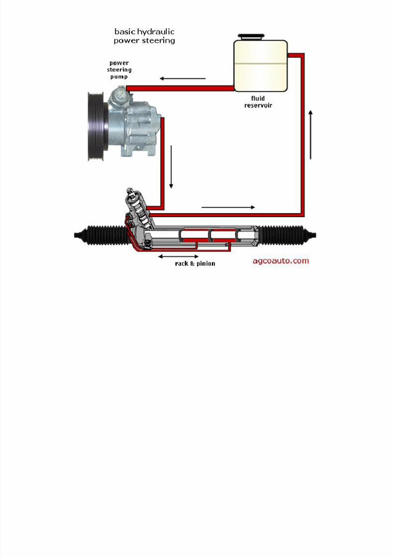
Hydraulic Power Steering (HPS)
Electric/electronic Power Steerin (EPS)

7/29/2019 3 Steering System Updated
http://slidepdf.com/reader/full/3-steering-system-updated 48/98

7/29/2019 3 Steering System Updated
http://slidepdf.com/reader/full/3-steering-system-updated 49/98

7/29/2019 3 Steering System Updated
http://slidepdf.com/reader/full/3-steering-system-updated 50/98

7/29/2019 3 Steering System Updated
http://slidepdf.com/reader/full/3-steering-system-updated 51/98

7/29/2019 3 Steering System Updated
http://slidepdf.com/reader/full/3-steering-system-updated 52/98
Reservoir pump hose
Return hose
Pump - controlvalve hose

7/29/2019 3 Steering System Updated
http://slidepdf.com/reader/full/3-steering-system-updated 53/98

7/29/2019 3 Steering System Updated
http://slidepdf.com/reader/full/3-steering-system-updated 54/98

7/29/2019 3 Steering System Updated
http://slidepdf.com/reader/full/3-steering-system-updated 55/98

7/29/2019 3 Steering System Updated
http://slidepdf.com/reader/full/3-steering-system-updated 56/98

7/29/2019 3 Steering System Updated
http://slidepdf.com/reader/full/3-steering-system-updated 57/98

7/29/2019 3 Steering System Updated
http://slidepdf.com/reader/full/3-steering-system-updated 58/98

7/29/2019 3 Steering System Updated
http://slidepdf.com/reader/full/3-steering-system-updated 59/98

7/29/2019 3 Steering System Updated
http://slidepdf.com/reader/full/3-steering-system-updated 60/98
7/29/2019 3 Steering System Updated
http://slidepdf.com/reader/full/3-steering-system-updated 61/98
7/29/2019 3 Steering System Updated
http://slidepdf.com/reader/full/3-steering-system-updated 62/98

7/29/2019 3 Steering System Updated
http://slidepdf.com/reader/full/3-steering-system-updated 63/98

7/29/2019 3 Steering System Updated
http://slidepdf.com/reader/full/3-steering-system-updated 64/98

7/29/2019 3 Steering System Updated
http://slidepdf.com/reader/full/3-steering-system-updated 65/98

7/29/2019 3 Steering System Updated
http://slidepdf.com/reader/full/3-steering-system-updated 66/98

7/29/2019 3 Steering System Updated
http://slidepdf.com/reader/full/3-steering-system-updated 67/98

7/29/2019 3 Steering System Updated
http://slidepdf.com/reader/full/3-steering-system-updated 68/98

7/29/2019 3 Steering System Updated
http://slidepdf.com/reader/full/3-steering-system-updated 69/98

7/29/2019 3 Steering System Updated
http://slidepdf.com/reader/full/3-steering-system-updated 70/98

7/29/2019 3 Steering System Updated
http://slidepdf.com/reader/full/3-steering-system-updated 71/98

7/29/2019 3 Steering System Updated
http://slidepdf.com/reader/full/3-steering-system-updated 72/98

7/29/2019 3 Steering System Updated
http://slidepdf.com/reader/full/3-steering-system-updated 73/98

7/29/2019 3 Steering System Updated
http://slidepdf.com/reader/full/3-steering-system-updated 74/98

7/29/2019 3 Steering System Updated
http://slidepdf.com/reader/full/3-steering-system-updated 75/98

7/29/2019 3 Steering System Updated
http://slidepdf.com/reader/full/3-steering-system-updated 76/98

7/29/2019 3 Steering System Updated
http://slidepdf.com/reader/full/3-steering-system-updated 77/98

7/29/2019 3 Steering System Updated
http://slidepdf.com/reader/full/3-steering-system-updated 78/98

7/29/2019 3 Steering System Updated
http://slidepdf.com/reader/full/3-steering-system-updated 79/98

7/29/2019 3 Steering System Updated
http://slidepdf.com/reader/full/3-steering-system-updated 80/98

7/29/2019 3 Steering System Updated
http://slidepdf.com/reader/full/3-steering-system-updated 81/98
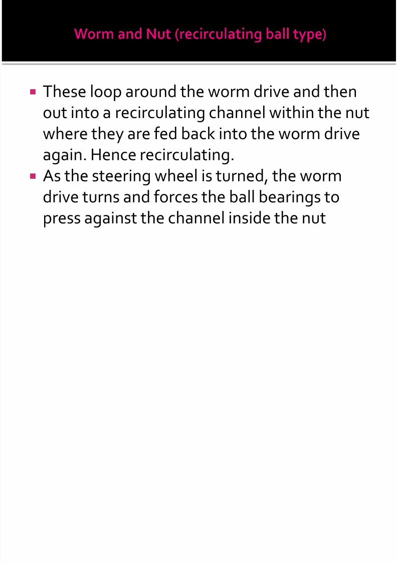
For a right turn, the control valve routes oil tothe left side of the power piston. The piston ispushed to the right in the cylinder to aidpitman shaft rotation.
For a left turn, the control valve routes oil to
the right side of the power piston. The pistonis pushed to the left in the cylinder to aidpitman shaft rotation.

7/29/2019 3 Steering System Updated
http://slidepdf.com/reader/full/3-steering-system-updated 82/98

7/29/2019 3 Steering System Updated
http://slidepdf.com/reader/full/3-steering-system-updated 83/98

7/29/2019 3 Steering System Updated
http://slidepdf.com/reader/full/3-steering-system-updated 84/98

7/29/2019 3 Steering System Updated
http://slidepdf.com/reader/full/3-steering-system-updated 85/98
To bleed out any air, start the engine and turnthe steering wheel fully from side to side.Keep checking the fluid and add as needed.This will force the air into the reservoir andout of the system.

7/29/2019 3 Steering System Updated
http://slidepdf.com/reader/full/3-steering-system-updated 86/98

7/29/2019 3 Steering System Updated
http://slidepdf.com/reader/full/3-steering-system-updated 87/98

7/29/2019 3 Steering System Updated
http://slidepdf.com/reader/full/3-steering-system-updated 88/98

7/29/2019 3 Steering System Updated
http://slidepdf.com/reader/full/3-steering-system-updated 89/98

7/29/2019 3 Steering System Updated
http://slidepdf.com/reader/full/3-steering-system-updated 90/98

7/29/2019 3 Steering System Updated
http://slidepdf.com/reader/full/3-steering-system-updated 91/98

7/29/2019 3 Steering System Updated
http://slidepdf.com/reader/full/3-steering-system-updated 92/98

7/29/2019 3 Steering System Updated
http://slidepdf.com/reader/full/3-steering-system-updated 93/98

7/29/2019 3 Steering System Updated
http://slidepdf.com/reader/full/3-steering-system-updated 94/98

7/29/2019 3 Steering System Updated
http://slidepdf.com/reader/full/3-steering-system-updated 95/98

7/29/2019 3 Steering System Updated
http://slidepdf.com/reader/full/3-steering-system-updated 96/98

7/29/2019 3 Steering System Updated
http://slidepdf.com/reader/full/3-steering-system-updated 97/98

7/29/2019 3 Steering System Updated
http://slidepdf.com/reader/full/3-steering-system-updated 98/98