3. How much torque or force does it take to drive the ... · COSMOSMotion is a module of the...
18
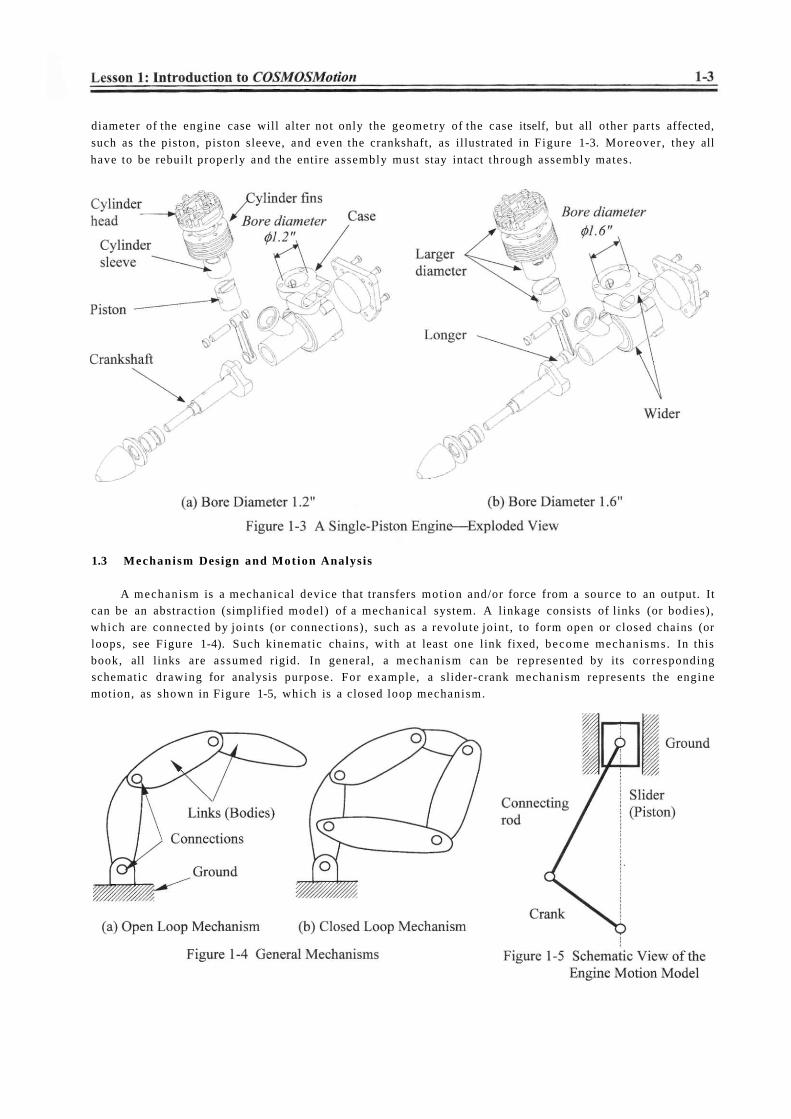
The purpose of this lesson is to provide you with a brief overview on COSMOSMotion. COSMOSMotion is a virtual prototyping tool that supports mechanism analysis and design. Instead of building and testing physical prototypes of the mechanism, you may use COSMOSMotion to evaluate and refine the mechanism before finalizing the design and entering the functional prototyping stage. COSMOSMotion will help you analyze and eventually design better engineering products. More specifically, the software enables you to size motors and actuators, determine power consumption, layout linkages, develop cams, understand gear drives, size springs and dampers, and determine how contacting parts behave, which would usually require tests of physical prototypes. With such information, you will gain insight on how the mechanism works and why it behaves in certain ways. You will be able to modify the design and often achieve better design alternatives using the more convenient and less expensive virtual prototypes. In the long run, using virtual prototyping tools, such as COSMOSMotion, will help you become a more experienced and competent design engineer. In this lesson, we will start with a brief introduction to COSMOSMotion and the various types of physical problems that COSMOSMotion is capable of solving. We will then discuss capabilities offered by COSMOSMotion for creating motion models, conducting motion analyses, and viewing motion analysis results. In the final section, we will mention examples employed in this book and topics to learn from these examples. Note that materials presented in this lesson will be kept brief. More details on various aspects of mechanism design and analysis using COSMOSMotion will be given in later lessons. 1.2 What is COSMOSMotion? COSMOSMotion is a computer software tool that supports engineers to analyze and design mechanisms. COSMOSMotion is a module of the SolidWorks product family developed by SolidWorks Corporation. This software supports users to create virtual mechanisms that answer general questions in product design as described next. An internal combustion engine shown in Figures 1-1 and 1-2 will be used to illustrate some typical questions. 1. Will the components of the mechanism collide in operation? For example, will the connecting rod collide with the inner surface of the piston or the inner surface of the engine case during operation? 2. Will the components in the mechanism you design move according to your intent? For example, will the piston stay entirely in the piston sleeve? Will the system lock up when the firing force aligns vertically with the connecting rod?
Transcript of 3. How much torque or force does it take to drive the ... · COSMOSMotion is a module of the...
The purpose of this lesson is to provide you with a brief overview on COSMOSMotion.
COSMOSMotion is a virtual prototyping tool that supports mechanism analysis and design. Instead of building and testing physical prototypes of the mechanism, you m a y use COSMOSMotion to evaluate and refine the mechanism before finalizing the design and entering the functional prototyping stage. COSMOSMotion will help you analyze and eventually design better engineering products. More specifically, the software enables you to size motors and actuators, determine power consumption, layout l inkages, develop cams, understand gear drives, size springs and dampers, and determine h o w contacting parts behave, which would usually require tests of physical prototypes. With such information, you will gain insight on h o w the mechanism works and why i t behaves in certain ways . You will be able to modify the design and often achieve better design alternatives using the more convenient and less expensive virtual prototypes. In the long run, using virtual prototyping tools, such as COSMOSMotion, will help you become a more experienced and competent design engineer.
In this lesson, we will start with a brief introduction to COSMOSMotion and the various types of physical problems that COSMOSMotion is capable of solving. We will then discuss capabilities offered by COSMOSMotion for creating motion models , conducting motion analyses, and v iewing motion analysis results. In the final section, we will ment ion examples employed in this book and topics to learn from these examples.
No te that materials presented in this lesson will be kept brief. More details on various aspects of
mechanism design and analysis using COSMOSMotion will be given in later lessons.
1.2 W h a t is COSMOSMotion?
COSMOSMotion is a computer software tool that supports engineers to analyze and design
mechanisms. COSMOSMotion is a module of the SolidWorks product family developed by SolidWorks
Corporation. This software supports users to create virtual mechanisms that answer general questions in
product design as described next. An internal combust ion engine shown in Figures 1-1 and 1-2 will be
used to illustrate some typical questions.
1. Will the components of the mechanism collide in operation? For example, will the connecting rod
collide with the inner surface of the piston or the inner surface of the engine case during operation?
2. Will the components in the mechanism you design m o v e according to your intent? For example, will
the piston stay entirely in the piston sleeve? Will the system lock up when the firing force aligns
vertically with the connecting rod?

3. H o w much torque or force does i t take to drive the mechanism? For example, what will be the min imum firing load to m o v e the piston? Note that in this case, proper friction forces must be added to simulate the resistance of the mechanism before a realistic firing force can be calculated.
4. H o w fast will the components move; e.g., the longitudinal mot ion of the piston?
5. What is the reaction force or torque generated at a connection (also called joint or constraint)
between components (or bodies) during mot ion? For example, what is the reaction force at the jo in t between the connecting rod and the piston pin? This reaction force is critical since the structural integrity of the piston pin and the connecting rod mus t be ensured; i.e., they must be strong and durable enough to sustain the load in operation.
The capabilities available in COSMOSMotion also help you search for better design alternatives. A better design alternative is very much problem dependent. It is critical that a design problem be clearly defined by the designer up front before searching for better design alternatives. For the engine example, a better design alternative can be a design that reveals:
1. A smaller reaction force applied to the connecting rod, and
2. No collisions or interference between components .
In order to vary component sizes for exploring better design alternatives, the parts and assembly must be adequately parameterized to capture design intents. At the parts level, design parameterization implies creating solid features and relating dimensions properly. At the assembly level, design parameterization involves defining assembly mates and relating dimensions across parts. When a solid model is fully parameterized, a change in dimension value can be propagated to all parts affected automatically. Parts affected must be rebuilt successfully, and at the same t ime, they will have to maintain proper posit ion and orientation wi th respect to one another without violating any assembly mates or revealing part penetration or excessive gaps. For example, in this engine example, a change in the bore
diameter of the engine case will alter not only the geometry of the case itself, but all other parts affected,
such as the piston, piston sleeve, and even the crankshaft, as illustrated in Figure 1-3. Moreover , they all
have to be rebuilt properly and the entire assembly must stay intact through assembly mates.
1.3 Mechanism Design and Mot ion Analysis
A mechanism is a mechanical device that transfers mot ion and/or force from a source to an output. It can be an abstraction (simplified model ) of a mechanical system. A linkage consists of links (or bodies), which are connected by joints (or connections), such as a revolute joint , to form open or closed chains (or loops, see Figure 1-4). Such kinematic chains, with at least one link fixed, become mechanisms. In this book, all links are assumed rigid. In general, a mechanism can be represented by its corresponding schematic drawing for analysis purpose. For example, a slider-crank mechanism represents the engine motion, as shown in Figure 1-5, which is a closed loop mechanism.

In general, there are two types of mot ion problems that you will have to solve in order to answer questions regarding mechanism analysis and design: kinematic and dynamic.
Kinemat ics is the study of mot ion wi thout regard for the forces that cause the motion. A kinematic
mechanism mus t be driven by a servomotor (or mot ion driver) so that the position, velocity, and
acceleration of each link of the mechanism can be analyzed at any given t ime. Typically, a kinematic
analysis must be conducted before dynamic behavior of the mechanism can be simulated properly.
Dynamic analysis is the study of mot ion in response to externally applied loads. The dynamic
behavior of a mechanism is governed by N e w t o n ' s laws of motion. The simplest dynamic problem is the
particle dynamics introduced in Sophomore Dynamics—for example, a spr ing-mass-damper system
shown in Figure 1-6. In this case, mot ion of the mass is governed by the following equation derived from
N e w t o n ' s second law,
(1.1)
where (•) appearing on top of the physical quantities represents t ime derivative of the quantities, m is the total mass of the block, k is the spring constant, and c is the damping coefficient.
For a rigid body, mass properties (such as the total mass , center of mass , moment of inertia, etc.) are taken into account for dynamic analysis. For example, mot ion of a pendulum shown in Figure 1-7 is governed by the following equation of motion,
YdM = -mgl s i n 0 = 10 = m£20 (1.2)
where M is the external momen t (or
torque), / is the polar momen t of
inertia of the pendulum, m is the
pendulum mass , g is the gravitational
acceleration, and 6 is the angular
acceleration of the pendulum.
Dynamic analysis of a rigid body system, such as the single piston engine shown in Figure 1-3, is a lot more complicated than the single body problems. Usually, a system of differential and algebraic equations governs the mot ion and the dynamic behavior of the system. N e w t o n ' s law must be obeyed by every single body in the system at all t ime. The motion of the system will be determined by the loads acting on the bodies or jo in t axes (e.g., a torque driving the system). Reaction loads at the joint connections hold the bodies together.
Note that in COSMOSMotion, you may create a kinematic analysis model ; e.g., using a mot ion driver to drive the mechanism; and then carry out dynamic analyses. In dynamic analysis, position, velocity, and acceleration results are identical to those of kinematic analysis. However , the inertia of the bodies will be taken into account for analysis; therefore, reaction forces will be calculated between bodies.
1.4 COSMOSMotion Capabilit ies Ground Parts
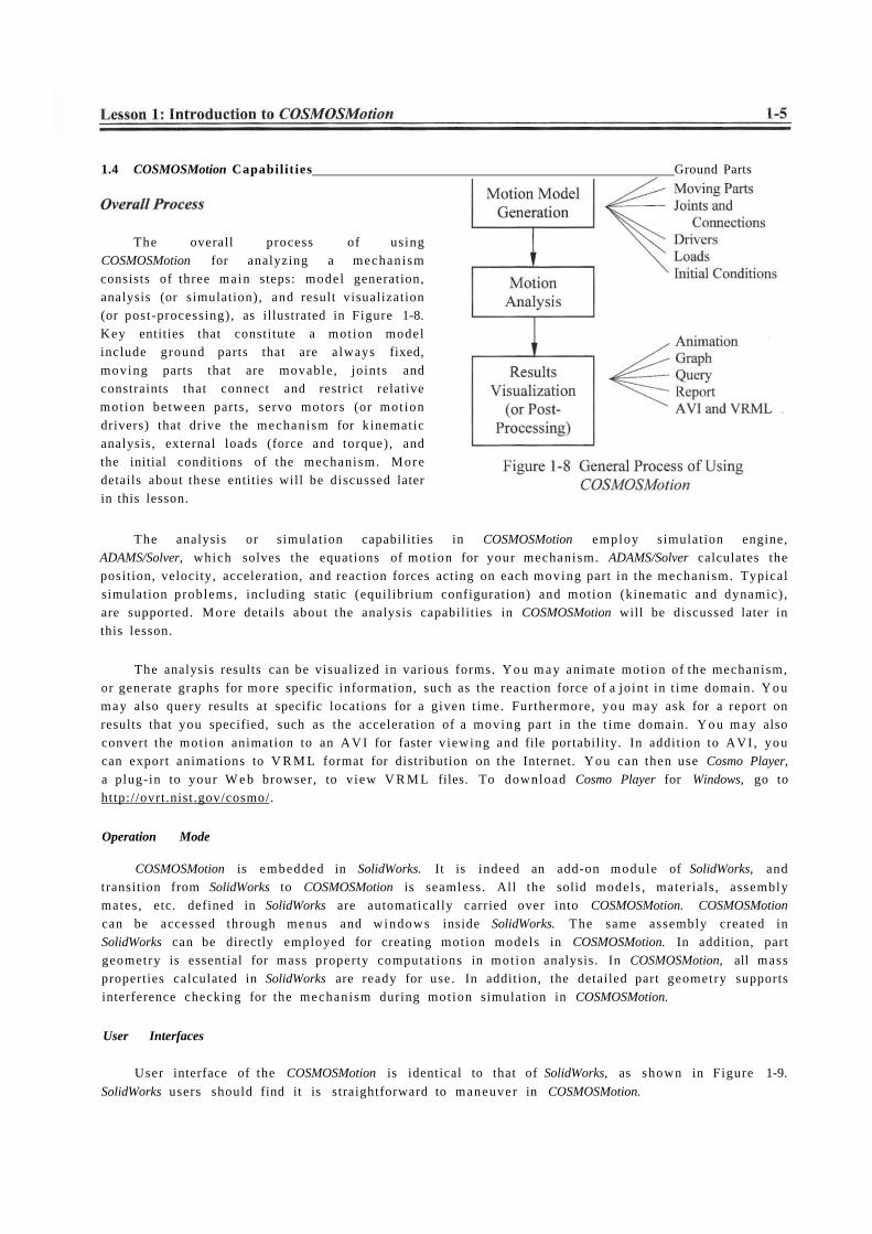
The overall process of using COSMOSMotion for analyzing a mechanism consists of three main steps: model generation, analysis (or simulation), and result visualization (or post-processing), as illustrated in Figure 1-8. Key entities that constitute a mot ion model include ground parts that are always fixed, moving parts that are movable , joints and constraints that connect and restrict relative mot ion be tween parts, servo motors (or mot ion drivers) that drive the mechanism for kinematic analysis, external loads (force and torque), and the initial conditions of the mechanism. More details about these entities will be discussed later in this lesson.
The analysis or simulation capabilities in COSMOSMotion employ simulation engine, ADAMS/Solver, which solves the equations of mot ion for your mechanism. ADAMS/Solver calculates the position, velocity, acceleration, and reaction forces acting on each moving part in the mechanism. Typical simulation problems, including static (equilibrium configuration) and motion (kinematic and dynamic) , are supported. M o r e details about the analysis capabilities in COSMOSMotion will be discussed later in this lesson.
The analysis results can be visualized in various forms. Y o u m a y animate motion of the mechanism, or generate graphs for more specific information, such as the reaction force of a jo int in t ime domain. Y o u may also query results at specific locations for a given t ime. Furthermore, you may ask for a report on results that you specified, such as the acceleration of a moving part in the t ime domain. Y o u may also convert the mot ion animation to an A V I for faster v iewing and file portability. In addition to AVI , you can export animations to V R M L format for distribution on the Internet. You can then use Cosmo Player,
a plug-in to your W e b browser, to v iew V R M L files. To download Cosmo Player for Windows, go to http://ovrt.nist .gov/cosmo/.
Operation Mode
COSMOSMotion is embedded in SolidWorks. It is indeed an add-on module of SolidWorks, and transition from SolidWorks to COSMOSMotion is seamless. All the solid models , materials , assembly mates , etc. defined in SolidWorks are automatically carried over into COSMOSMotion. COSMOSMotion
can be accessed through menus and windows inside SolidWorks. The same assembly created in SolidWorks can be directly employed for creating motion models in COSMOSMotion. In addition, part geometry is essential for mass property computat ions in mot ion analysis. In COSMOSMotion, all mass properties calculated in SolidWorks are ready for use. In addition, the detailed part geometry supports interference checking for the mechanism during mot ion simulation in COSMOSMotion.
User Interfaces
User interface of the COSMOSMotion is identical to that of SolidWorks, as shown in Figure 1-9.
SolidWorks users should find it is straightforward to maneuver in COSMOSMotion.
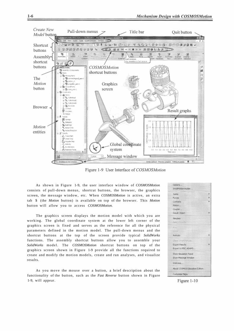
As shown in Figure 1-9, the user interface window of COSMOSMotion
consists of pul l -down menus , shortcut buttons, the browser, the graphics
screen, the message window, etc. When COSMOSMotion is active, an extra
tab $ (the Motion button) is available on top of the browser. This Motion
button will allow you to access COSMOSMotion.
The graphics screen displays the motion model with which you are working. The global coordinate system at the lower left corner of the graphics screen is fixed and serves as the reference for all the physical parameters defined in the motion model . The pul l -down menus and the shortcut buttons at the top of the screen provide typical SolidWorks
functions. The assembly shortcut buttons allow you to assemble your SolidWorks model . The COSMOSMotion shortcut buttons on top of the graphics screen shown in Figure 1-9 provide all the functions required to create and modify the motion models , create and run analyses, and visualize results.
As you m o v e the mouse over a button, a brief description about the
functionality of the button, such as the Fast Reverse button shown in Figure
1-9, will appear.

When you choose a menu option, the Message window, at the lower left corner shown in Figure 1-9,
shows a brief description about the option. In addition to these buttons, a COSMOSMotion pul l -down
menu also provides similar options, as shown in Figure 1-10.
W h e n you click the Motion button, the browser will provide you with a graphical, hierarchical v iew
of mot ion model and allow you to access all COSMOSMotion functionalities through a combinat ion of
drag-and-drop and right-click activated menus .
For example, you may drag and drop connectingrod_asm-l
under the Assembly Components,
as shown in Figure 1-11 to Moving Parts under the Parts
branch to define it as a moving part. Y o u m a y also right click an entity and choose to define or edit its property. For example, you may right click the Springs node under Forces branch in Figure 1-12, and choose Add Translational
Spring to add a spring.
Switching back and forth between COSMOSMotion and SolidWorks assembly m o d e is
straightforward. All you have to do is to click the Motion J? or Assembly buttons ^ (on top of the
browser) when needed. When you click the Motion button <f? to enter COSMOSMotion, a different set of
entities will be listed in the browser. In addition, an additional toolbar is added to SolidWorks, located at
the top of the graphics screen, as depicted in Figure 1-13. They are the COSMOSMotion shortcut buttons
shown in Figure 1-9. This toolbar provides settings, simulation and post processing features. Especially,
the Play Simulation button is handy when you finish running a simulation and are ready to animate the motion. Click some of the buttons and try to get familiar with their functions. The shortcut buttons in COSMOSMotion and their functions are also summarized in Table 1-1 with a few more details.

tabbed dialog box and a wizard that leads you through the process of convert ing an assembly model into a mot ion model , performing motion simulations, and viewing simulation results.

To use the IntelliMotion Builder, click the
IntelliMotion Builder but ton or right-click the
Motion Model node (the root entity of the mot ion
model) from the browser, and then select
IntelliMotion Builder (see Figure 1-14). The first
tab is Units, which brings up the Units page.
At the lower-left corner of each page in the
IntelliMotion Builder are the Back and Next
buttons, which help you m o v e sequentially
through the mot ion mode l creation, simulation,
and animation process. Y o u may also click a tab
on top to j u m p to that page directly, for example
Parts, to define ground and moving parts. For a
new COSMOSMotion user, the IntelliMotion
Builder is very helpful in terms of leading you
through the steps of creating simulations models ,
running simulations, and visualizing the
simulation results. For a more experienced user,
the drag-and-drop and right-click activated menus
may be more convenient.
Table 1-2 gives a brief explanation of each tab available in the IntelliMotion Builder.
Defining COSMOSMotion Entities
The basic entities of a val id COSMOSMotion s imulation model consist of ground parts, moving
parts, constraints (including joints) , initial conditions, and forces and/or drivers. Each of the basic entities
will be briefly discussed next. More details can be found in later lessons.

Ground Parts (or Ground Body)
A ground part, or a ground body, represents a fixed reference in space. The first component brought
into the assembly is usually stationary; therefore, often becoming a ground part. You will have to identify
moving and non-moving parts in your assembly, and assign the non-moving parts as ground parts using
either the IntelliMotion Builder or the drag-and-drop in the browser.
Moving Parts (or Bodies)
A moving part or body is an entity represents a single rigid component (or link) that moves relatively
to other parts (or bodies) . A moving part m a y consist of a single SolidWorks part or an assembly
composed of multiple parts. W h e n an assembly is assigned as a moving part, none of its composing parts
is al lowed to move relative to one another within the assembly. A moving part has six degrees of
freedom, three translational and three rotational, while a ground part has none. That is, a rigid body can
translate and rotate along the Y-, and Z-axes of a coordinate system. Rotat ion of a rigid body is
measured by referring the orientation of its local coordinate system to the global coordinate system, which
is shown at the lower left corner on the graphics screen. In COSMOSMotion, the local coordinate system
is assigned automatically, usually, at the mass center of the part. Mass properties, including total mass ,
inertia, etc., are calculated using part geometry and material properties referring to the local coordinate
system. A moving part has a symbol (see Figure l -16a) attached, usually located at its mass center, as
shown in Figure 1-15.
Constraints
A constraint (or connection) in COSMOSMotion can be a joint , contact, or coupler that connects two
parts and constrains the relative mot ion between them. Typical joints include a revolute, cylindrical,
spherical, etc. Each independent movement permit ted by a constraint is a free degree of freedom (dof).
The degrees of freedom that a constraint allows can be translational or rotational along the three
perpendicular axes. The free dof is revealed by the symbol of the constraint. For example, the symbol of
cylindrical jo ints , such as those defined in the engine example shown in Figure 1-15, show two concentric
cylinders implying two free d o f s, a translational and a rotational, both are along the c o m m o n axis, as
illustrated in Figure l -16b . Also, a revolute joint , for example the one between the propeller and the case
shown in Figure 1-15, allows only one rotational dof, as depicted in a hinge symbol shown in Figure 1-
16c. Understanding the jo in t symbols will enable you to read existing mot ion models . Also, a jo in t
produces equal and opposite reactions (forces and/or torques) on the bodies connected due to N e w t o n ' s
3 r d Law. More about jo ints will be discussed in later lessons and for a list of commonly employed joints ,
please refer to Appendix A.
COSMOSMotion automatically converts assembly mates to joints . For example, a concentric mate
together with a coincident mate will be converted to a revolute joint . Sometimes, COSMOSMotion will
simply carry over the assembly mates to mot ion if there is no adequate jo in t to convert to , following the
mapped mates established internally. For a list of common mapped mates , please refer to Appendix A.
You may either stay wi th the jo in t set converted by COSMOSMotion or delete some of them to create
your own. However , i t is strongly recommended that you stay with the converted jo in t set before
complet ing all the examples provided in this book. In all the examples presented in this book, mapped
joints or mates are employed without any modification.
Note that instead of completely fixing all the movements , certain d o f s (translational and/or
rotational) are left to allow designated movement . For example, a mot ion driver is defined at the rotation
dof of the revolute jo in t in the engine example, as shown in Figure 1-15. This mot ion driver will rotate the
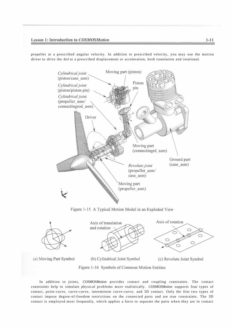
propeller at a prescribed angular velocity. In addition to prescribed velocity, you m a y use the mot ion
driver to drive the dof at a prescribed displacement or acceleration, both translation and rotational.
In addition to joints , COSMOSMotion provides contact and coupling constraints. The contact
constraints help to simulate physical problems more realistically. COSMOSMotion supports four types of
contact, point-curve, curve-curve, intermittent curve-curve, and 3D contact. Only the first two types of
contact impose degree-of-freedom restrictions on the connected parts and are true constraints. The 3D
contact is employed most frequently, which applies a force to separate the parts when they are in contact
and prevent them from penetrating each other. The 3D contact constraint will become active as soon as
the parts are touching.
Joint couplers al low the mot ion of a revolute, cylindrical, or translational jo in t to be coupled to the
mot ion of another revolute, cylindrical or translational joint . The two coupled jo ints m a y be of the same
or different types. For example, a revolute jo in t m a y be coupled to a translational joint . The coupled
mot ion m a y also be of the same or different type. For example, the rotary mot ion of a revolute jo in t may
be coupled to the rotary mot ion of a cylindrical joint , or the translational mot ion of a translational jo in t
m a y be coupled to the rotary mot ion of a cylindrical joint . A coupler removes one additional degree of
freedom from the mot ion model .
Degrees of Freedom
As ment ioned earlier, an unconstrained body in space has six degrees of freedom; i.e., three
translational and three rotational. When joints are added to connect bodies, constraints are imposed to
restrict the relative mot ion between them.
For example, the revolute jo int defined in the engine example restricts movement on five d o f s so
that only one rotational mot ion is a l lowed between the propeller assembly and the engine case. Since the
engine case is a ground body, the propeller assembly will rotate along the axis of the revolute joint , as
illustrated in the symbol shown in Figure 1-16b. Therefore, there is only one degree of freedom left for
the propeller assembly. For a given mot ion model , you can determine its number of degrees of freedom
using the Gruebler ' s count.
COSMOSMotion uses the following equation to calculate the Gruebler ' s count:
D = 6M-N-0 (1.3)
where D is the Gruebler ' s count representing the total degrees of freedom of the mechanism, M i s the
number of bodies excluding the ground body, TV is the number of d o f s restricted by all jo ints , and O is the
number of mot ion drivers defined in the system.
In general, a val id mot ion model should have a Gruebler ' s count 0. However , in creating motion
models , some joints remove redundant d o f s . For example, two hinges, mode led using two revolute joints ,
support a door. The second revolute jo in t adds five redundant d o f s. The Gruebler ' s count becomes:
D = 6x1 -2x5 = -4
For kinematic analysis, the Gruebler ' s count must be equal to or less than 0. The ADAMS/Solver
recognizes and deactivates redundant constraints during analysis. For a kinematic analysis, if you create a
model and try to animate it wi th a Gruebler ' s count greater than 0, the animation will not run and an error
message will appear.
The single-piston engine shown in Figure 1-15 consists of three bodies (excluding the ground body) ,
one revolute jo in t and three cylindrical joints . A revolute jo in t removes five degrees of freedom, and a
cylindrical jo int removes four d o f s. In addition, a mot ion driver is added to the rotational dof of the
revolute joint . Therefore, according to Eq. 1.3, the Gruebler ' s count for the engine example is
If the Gruebler ' s count is less than zero, the solver will automatically remove redundancies . In this
engine example, i f the two of the cylindrical jo ints ; be tween piston and the piston pin, and between the
connecting rod and the crank shaft, are replaced by revolute joints , the Gruebler ' s count becomes
D = 6x(4-l)-(3x5-1x4) - lxl = -2
To get the Gruebler ' s count to zero, it is often possible to replace joints that remove a large number
of constraints with joints that remove a smaller number of constraints and still restrict the mechanism
mot ion in the same way. COSMOSMotion detects the redundancies and ignores redundant d o f s in all
analyses, except for dynamic analysis. In dynamic analysis, the redundancies lead to an outcome with a
possibility of incorrect reaction results, yet the mot ion is correct. For complete and accurate reaction
forces, i t is critical that you eliminate redundancies from your mechanism. The challenge is to find the
joints that will impose non-redundant constraints and still al low for the intended motion. Examples
included in this book should give you some ideas in choosing proper jo ints .
Forces
Forces are used to operate a mechanism. Physically, forces are produced by motors , springs,
dampers, gravity, tires, etc. A force entity in COSMOSMotion can be a force or torque. COSMOSMotion
provides three types of forces: applied forces, flexible connectors, and gravity.
Appl ied forces are forces that cause the mechanism to m o v e in certain ways . Appl ied forces are very
general, but you mus t supply your own description of the force by specifying a constant force value or
expression function, such as a harmonic function. The applied forces in COSMOSMotion include action-
only force or momen t (where force or m o m e n t is applied at a point on a single rigid body, and no reaction
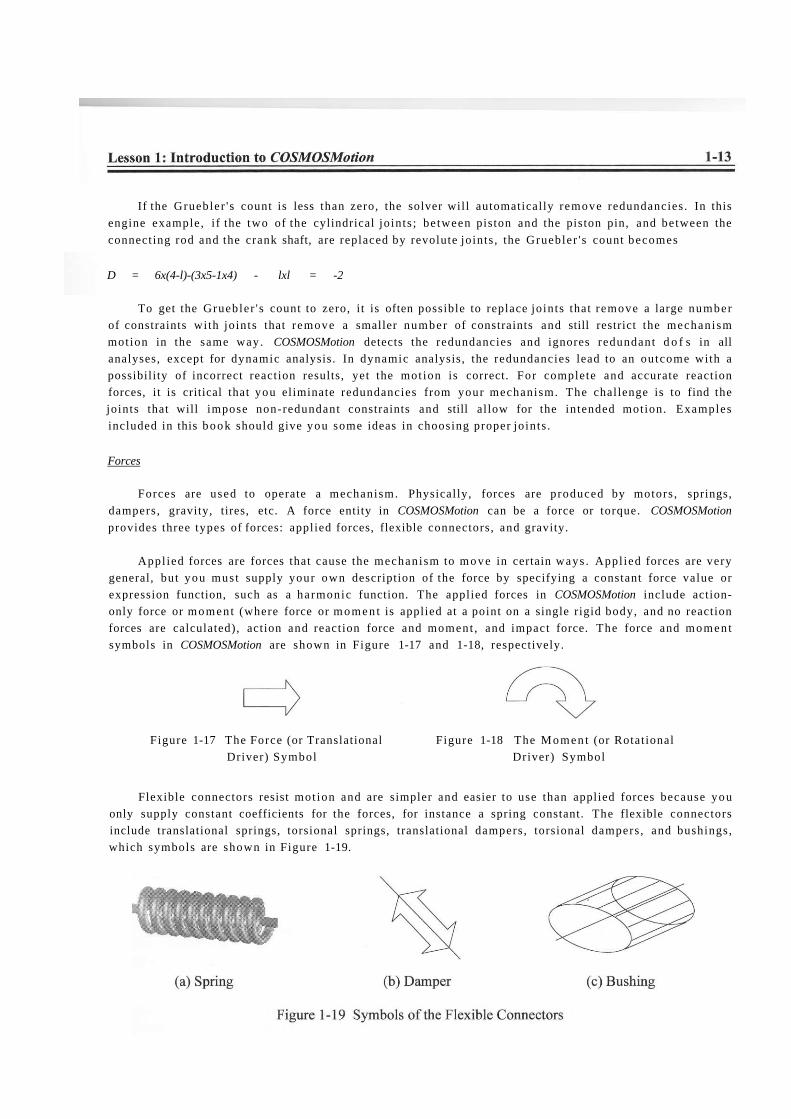
forces are calculated), action and reaction force and moment , and impact force. The force and momen t
symbols in COSMOSMotion are shown in Figure 1-17 and 1-18, respectively.
Figure 1-17 The Force (or Translational Figure 1-18 The Momen t (or Rotational
Driver) Symbol Driver) Symbol
Flexible connectors resist mot ion and are simpler and easier to use than applied forces because you
only supply constant coefficients for the forces, for instance a spring constant. The flexible connectors
include translational springs, torsional springs, translational dampers , torsional dampers , and bushings,
which symbols are shown in Figure 1-19.

A magni tude and a direction must be included for a force definition. You m a y select a predefined
function, such as a harmonic function, to define the magni tude of the force or moment . For spring and
damper, COSMOSMotion automatically makes the force magni tude proportional to the distance or
velocity between two points , based on the spring constant and damping coefficient entered, respectively.
The direction of a force (or moment ) can be defined by either along an axis defined by an edge or along
the line between two points, where a spring or a damper is defined.
Initial Conditions
In motion simulations, initial conditions consist of initial configuration of the mechanism and initial
velocity of one or more components of the mechanism. Mot ion simulation must start with a properly
assembled solid model that determines an initial configuration of the mechanism, composed by posit ion
and orientation of individual components . The initial configuration can be completely defined by
assembly mates . However , one or more assembly mates will have to be suppressed, i f the assembly is
fully constrained, to provide adequate movement .
In COSMOSMotion, initial velocity is defined as part of definition of a moving part. The initial
velocity can be translational or rotational along one of the three axes.
Motion Drivers
Motion drivers are used to impose a particular movement of a jo in t or part over t ime. A mot ion
driver specifies position, velocity, or acceleration as a function of t ime, and can control either
translational or rotational motion. The driver symbol is identical to those of Figures 1-17 and 1-18, for
translational and rotational, respectively. When properly defined, mot ion drivers will account for the
remaining dof s of the mechan ism that brings the Gruebler ' s count to zero or less.
In the engine example shown in Figure 1-15, a mot ion driver is defined at the revolute jo int to rotate
the propeller at a constant angular velocity.
Motion Simulation
The ADAMS/Solver employed by COSMOSMotion is
capable of solving typical engineering problems, such as static
(equilibrium configuration), kinematic , and dynamic, etc.
Static analysis is used to find the rest position (equilibrium
condition) of a mechanism, in which none of the bodies are
moving . A simple example of the static analysis is illustrated in
Figure 1-20, in which an equil ibrium posit ion of the block is to
be determined according to its own mass m, the two spring
constants ki and k2, and the gravity g.
As discussed earlier, kinematics is the study of mot ion without regard for the forces that cause the
motion. A mechanism can be driven by a motion driver (e.g., a servomotor) for a kinematic analysis,
where the position, velocity, and acceleration of each link of the mechanism can be analyzed at any given
t ime. Figure 1-21 shows a servomotor drives a mechanism at a constant angular velocity.
Dynamic analysis is used to study the mechanism mot ion in response to loads, as illustrated in
Figure 1-22. This is the mos t complicated and common, and usually a more t ime-consuming analysis.
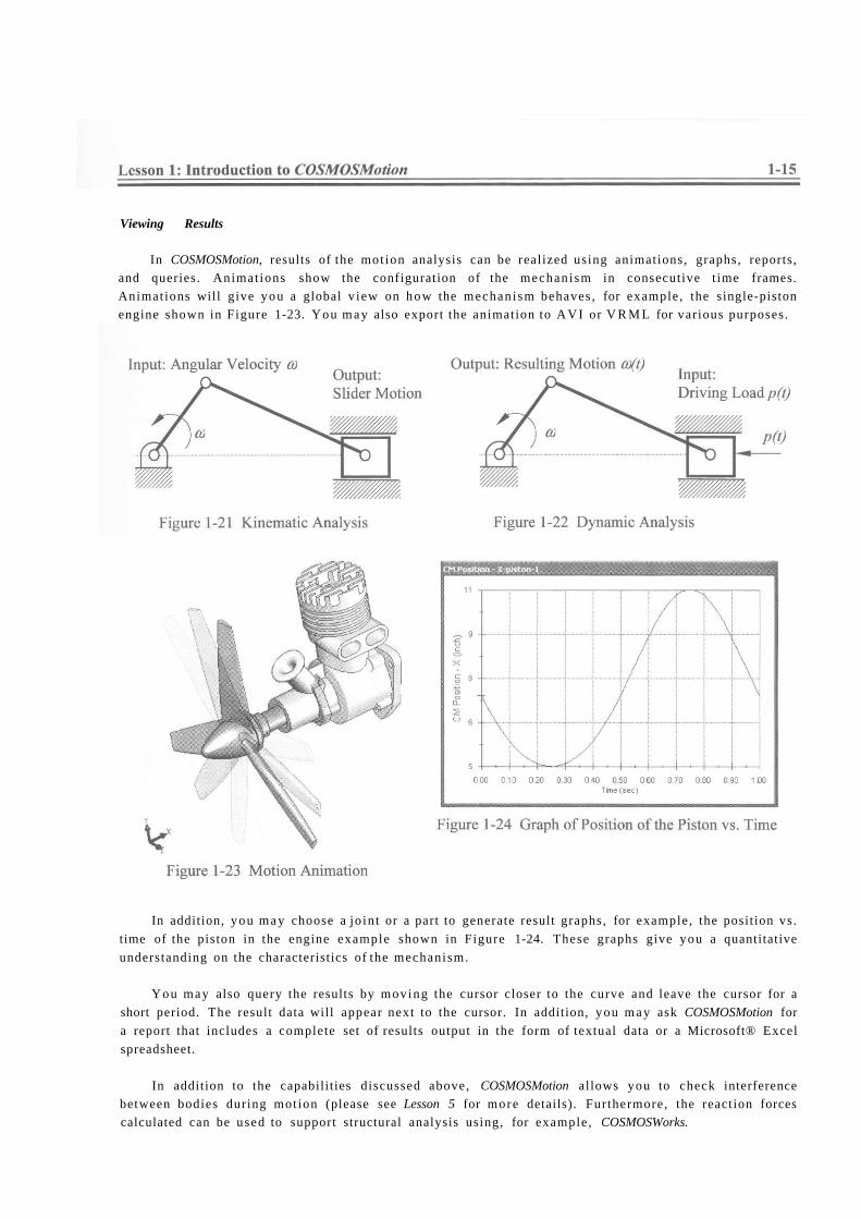
Viewing Results
In COSMOSMotion, results of the mot ion analysis can be realized using animations, graphs, reports,
and queries. Animat ions show the configuration of the mechanism in consecutive t ime frames.
Animations will give you a global v iew on how the mechanism behaves , for example, the single-piston
engine shown in Figure 1-23. You m a y also export the animation to A V I or V R M L for various purposes.
In addition, you m a y choose a jo in t or a part to generate result graphs, for example, the posit ion vs.
time of the piston in the engine example shown in Figure 1-24. These graphs give you a quantitative
understanding on the characteristics of the mechanism.
You may also query the results by moving the cursor closer to the curve and leave the cursor for a
short period. The result data will appear next to the cursor. In addition, you m a y ask COSMOSMotion for
a report that includes a complete set of results output in the form of textual data or a Microsoft® Excel
spreadsheet.
In addition to the capabilities discussed above, COSMOSMotion al lows you to check interference
between bodies during mot ion (please see Lesson 5 for more details). Furthermore, the reaction forces
calculated can be used to support structural analysis using, for example, COSMOSWorks.
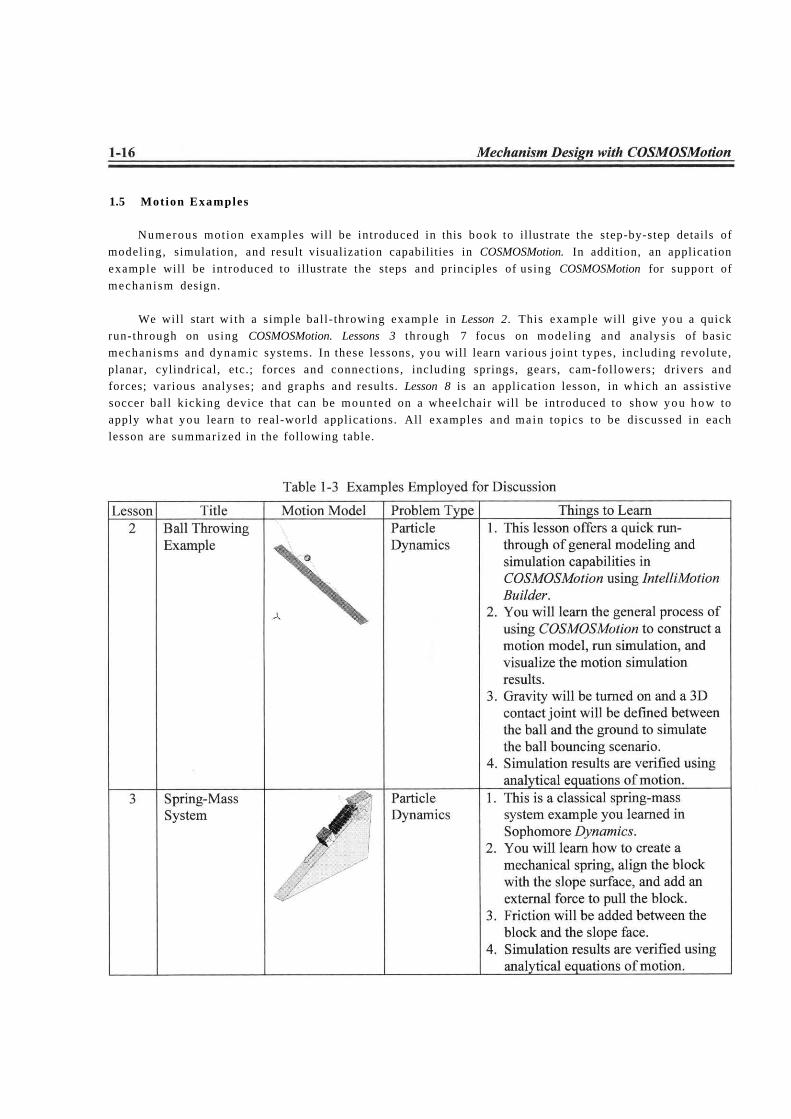
1.5 Motion Examples
Numerous motion examples will be introduced in this book to illustrate the step-by-step details of
model ing, simulation, and result visualization capabilities in COSMOSMotion. In addition, an application
example will be introduced to illustrate the steps and principles of using COSMOSMotion for support of
mechanism design.
We will start wi th a simple ball- throwing example in Lesson 2. This example will give you a quick
run-through on using COSMOSMotion. Lessons 3 through 7 focus on model ing and analysis of basic
mechanisms and dynamic systems. In these lessons, you will learn various jo in t types, including revolute,
planar, cylindrical, etc.; forces and connections, including springs, gears, cam-followers; drivers and
forces; various analyses; and graphs and results. Lesson 8 is an application lesson, in which an assistive
soccer ball kicking device that can be mounted on a wheelchair will be introduced to show you h o w to
apply what you learn to real-world applications. All examples and main topics to be discussed in each
lesson are summarized in the following table.