2D DRAWING REPRESENTATION
19
2D DRAWING REPRESENTATION C H A P T E R S E V E N
Transcript of 2D DRAWING REPRESENTATION
2D DRAWINGREPRESENTATION
C H A P T E R S E V E N
OBJECTIVES1. Represent curved surfaces in multiview drawings2. Show intersections and tangencies of curved and planar surfaces3. Represent common types of holes4. Show fillets, rounds, and runouts in a 2D drawing5. Use partial views6. Apply revolution conventions when necessary for clarity7. Draw removed views and projected views8. Show right- and left-hand parts9. Project curved surfaces by points10. Show and label an enlarged detail11. Show conventional breaks

Common Manufactured Features
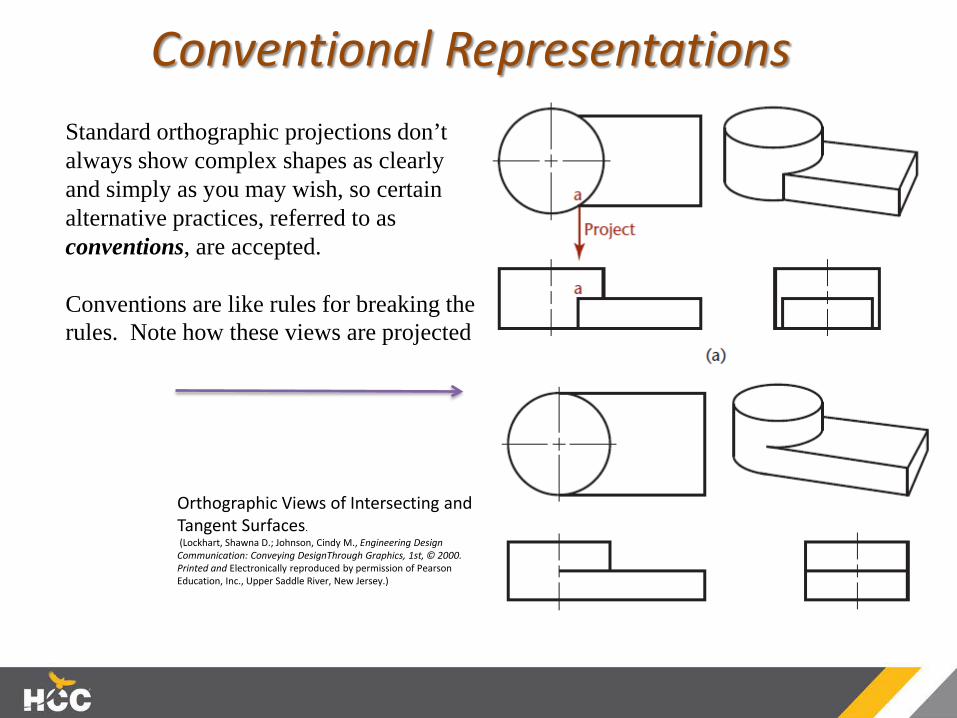
Conventional RepresentationsStandard orthographic projections don’t always show complex shapes as clearly and simply as you may wish, so certain alternative practices, referred to as conventions, are accepted.
Conventions are like rules for breaking the rules. Note how these views are projected
Orthographic Views of Intersecting and Tangent Surfaces.(Lockhart, Shawna D.; Johnson, Cindy M., Engineering Design Communication: Conveying DesignThrough Graphics, 1st, © 2000. Printed and Electronically reproduced by permission of Pearson Education, Inc., Upper Saddle River, New Jersey.)
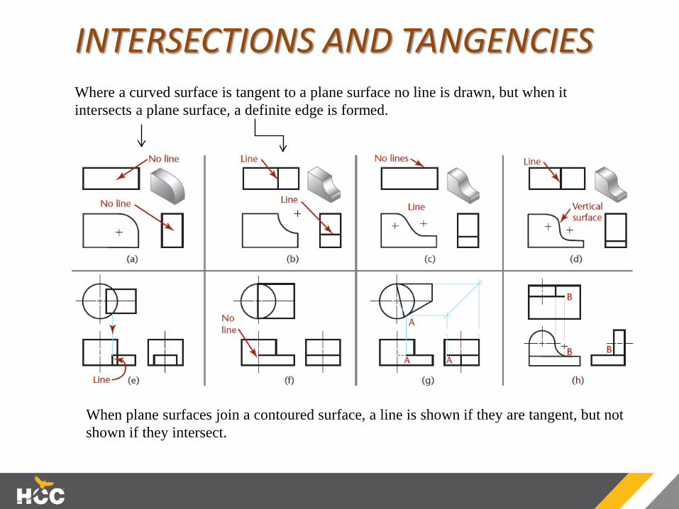
INTERSECTIONS AND TANGENCIESWhere a curved surface is tangent to a plane surface no line is drawn, but when it intersects a plane surface, a definite edge is formed.
When plane surfaces join a contoured surface, a line is shown if they are tangent, but not shown if they intersect.

Intersections of Cylinders
When the intersection is small, its curved shape is not plotted accurately because it adds little to the sketch or drawing for the time it takes. Instead it is shown as astraight line.
When the intersection is larger, it can be approximated by drawing an arc with the radius the same as that of the large cylinder.
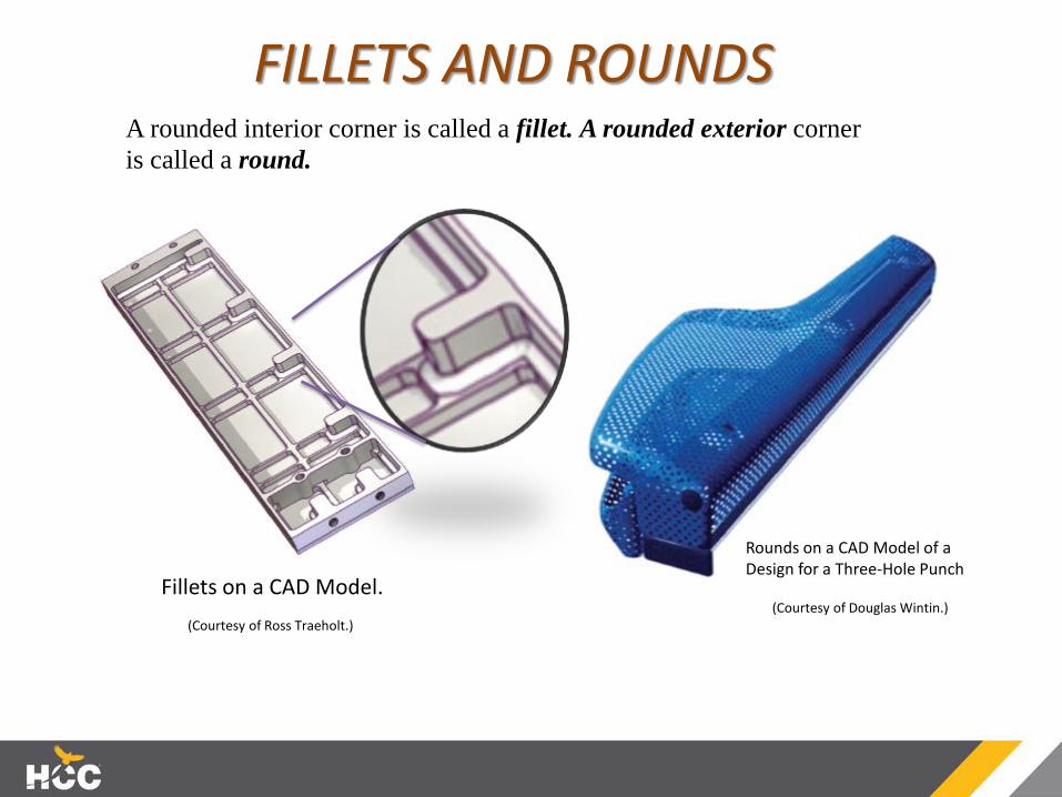
FILLETS AND ROUNDSA rounded interior corner is called a fillet. A rounded exterior corner is called a round.
(Courtesy of Ross Traeholt.)(Courtesy of Douglas Wintin.)
Rounds on a CAD Model of a Design for a Three-Hole Punch
Fillets on a CAD Model.

RUNOUTSSmall curves called runouts are used to represent fillets that connect with plane surfaces tangent to cylinders.
Runouts from different filleted intersections will appear different owing to the shapes of the horizontal intersectingmembers.

NECESSARY VIEWS
One-View Drawing
Two-View Drawing
Three-View Drawing
What are the absolute minimum viewsrequired to completely define an object?

PARTIAL VIEWSA view may not need to be complete but needs to show what is necessary to clearly describe the object. This is called a partial view and is used to save sketchingtime and make the drawing less confusing to read.
You can use a break line to limit the partial view…
OR
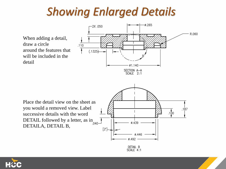
Showing Enlarged Details
When adding a detail, draw a circlearound the features that will be included in the detail
Place the detail view on the sheet as you would a removed view. Label successive details with the word DETAIL followed by a letter, as in DETAILA, DETAIL B,

Conventional BreaksTo shorten the view of a long object, you can use break lines…
Use a “break line” to leave out a portion of the part, this allows the scale for the ends to be increased to clearly show the details.

ALIGNMENT OF VIEWSAlways draw views in the “standard” arrangement...
Because CAD makes it easy to move whole views, it istempting to place views where they fit on the screen orplotted sheet and not in the standard arrangement. This is not acceptable.
3D CAD software that generates 2D drawing views asprojections of the 3D object usually has a setting to select from third-angle or first-angle projection. Check your software if you are unsure which projection methods are available.
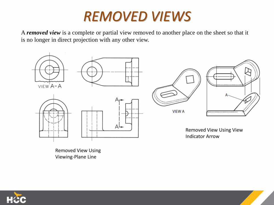
REMOVED VIEWSA removed view is a complete or partial view removed to another place on the sheet so that it is no longer in direct projection with any other view.
Removed View Using Viewing-Plane Line
Removed View Using View Indicator Arrow
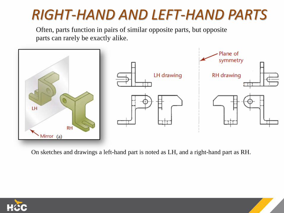
RIGHT-HAND AND LEFT-HAND PARTSOften, parts function in pairs of similar opposite parts, but oppositeparts can rarely be exactly alike.
On sketches and drawings a left-hand part is noted as LH, and a right-hand part as RH.
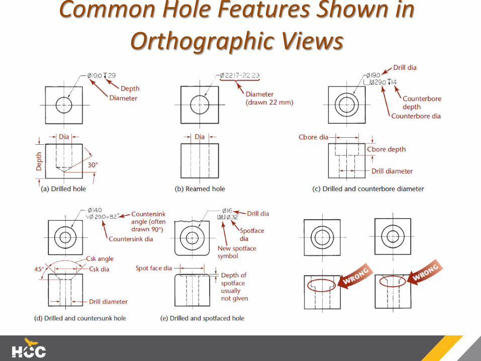
Common Hole Features Shown in Orthographic Views

Common Features Shown in Orthographic Views

Common Features Shown in Orthographic Views Continued…

Questions