24th ANNUAL MDEC CONFERENCE Toronto Airport Hilton Hotel ... · 24th ANNUAL MDEC CONFERENCE Toronto...
170
24 th ANNUAL MDEC CONFERENCE Toronto Airport Hilton Hotel, Canada October 2 – 4, 2018 MDEC DIESEL WORKSHOP Diesel Workshop - Battery Technology – Lithium Ion Cells and Diesel Engine Technology & DPF Strategies & Guidelines PRESENTED BY: Bapi Surampudi (SwRI) Evelynn Stirling (Cummins) Sean McGinn (MKNIZD Factors) Jan Czerwinski (AFHB) COORDINATED BY David Young (Natural Resources Canada) OCTOBER 4, 2018
Transcript of 24th ANNUAL MDEC CONFERENCE Toronto Airport Hilton Hotel ... · 24th ANNUAL MDEC CONFERENCE Toronto...
24th ANNUAL MDEC CONFERENCE Toronto Airport Hilton Hotel, Canada
October 2 – 4, 2018
MDEC DIESEL WORKSHOP Diesel Workshop - Battery Technology – Lithium Ion Cells
and Diesel Engine Technology & DPF Strategies & Guidelines
PRESENTED BY:
Bapi Surampudi (SwRI) Evelynn Stirling (Cummins)
Sean McGinn (MKNIZD Factors) Jan Czerwinski (AFHB)
COORDINATED BY
David Young (Natural Resources Canada)
OCTOBER 4, 2018
MDEC Diesel Workshop
Hilton Toronto Airport Hilton
Ontario, Canada
Thursday, October 4, 2018
BATTERY TECHNOLOGY – LITHIUM ION CELLS
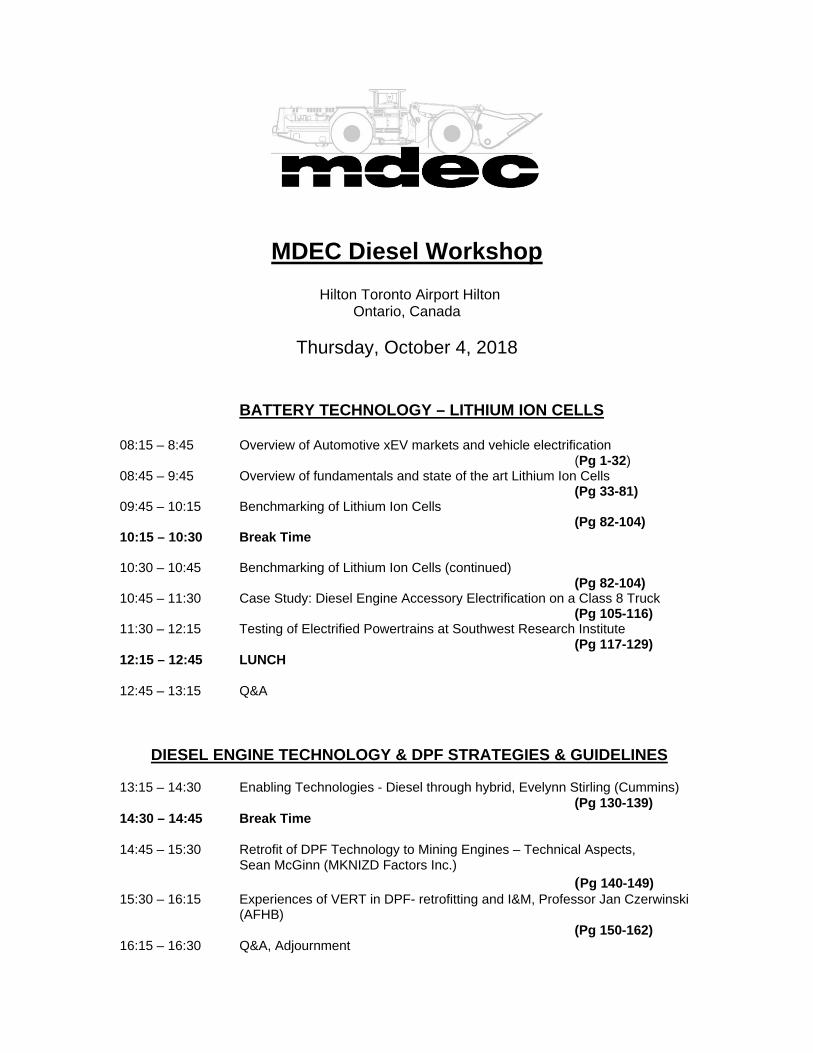
08:15 – 8:45 Overview of Automotive xEV markets and vehicle electrification (Pg 1-32) 08:45 – 9:45 Overview of fundamentals and state of the art Lithium Ion Cells (Pg 33-81) 09:45 – 10:15 Benchmarking of Lithium Ion Cells (Pg 82-104) 10:15 – 10:30 Break Time 10:30 – 10:45 Benchmarking of Lithium Ion Cells (continued) (Pg 82-104) 10:45 – 11:30 Case Study: Diesel Engine Accessory Electrification on a Class 8 Truck (Pg 105-116) 11:30 – 12:15 Testing of Electrified Powertrains at Southwest Research Institute (Pg 117-129) 12:15 – 12:45 LUNCH 12:45 – 13:15 Q&A
DIESEL ENGINE TECHNOLOGY & DPF STRATEGIES & GUIDELINES 13:15 – 14:30 Enabling Technologies - Diesel through hybrid, Evelynn Stirling (Cummins) (Pg 130-139) 14:30 – 14:45 Break Time 14:45 – 15:30 Retrofit of DPF Technology to Mining Engines – Technical Aspects, Sean McGinn (MKNIZD Factors Inc.) (Pg 140-149) 15:30 – 16:15 Experiences of VERT in DPF- retrofitting and I&M, Professor Jan Czerwinski
(AFHB) (Pg 150-162) 16:15 – 16:30 Q&A, Adjournment

MDEC – 2018 Workshop Address List
Craig Allair Bus: 705-675-3381 United Steelworkers Local 6500 Fax: 705-675-2438 66 Brady Street email: [email protected] Sudbury, Ontario P3E 1C8 Cheryl Allen Bus: 705-682-6857 Vale North Atlantic email: [email protected] 18 Rink Street Copper Cliff, Ontario P0M 1N0 Brett Andrews Bus: 705-499-7208 Cummins Canada ULC email: [email protected] 18 Vermont Crescent North Bay, Ontario P1C 1L5 Gabrielle Beauchamp Bus: 438-889-1767 Goldcorp email: [email protected] 1751 Davy Road Rouyn-Noranda, Quebec J9Y 0A8 Nathan Bergermann Nutrien Serge Blanchette Bus: 418-770-3512 Goldcorp email: [email protected] 1751 Davy Road Rouyn-Noranda, Quebec J9Y 0A8 Wallace Boehme Nutrien Wallace Boehme Nutrien Daniel Crossingham Bus: 306-203-1938 New Gold – New Afton email: [email protected] 1419 Waterloo Place Kamloops, British Columbia V2B 8G3 Ralph Deayton Mammoth Equipment and Exhaust Inc. Bob Deprez Bus: 585-728-8012 AirFlow Catalyst Systems email: [email protected] 2640 State Route 21 Wayland, New York USA 14572
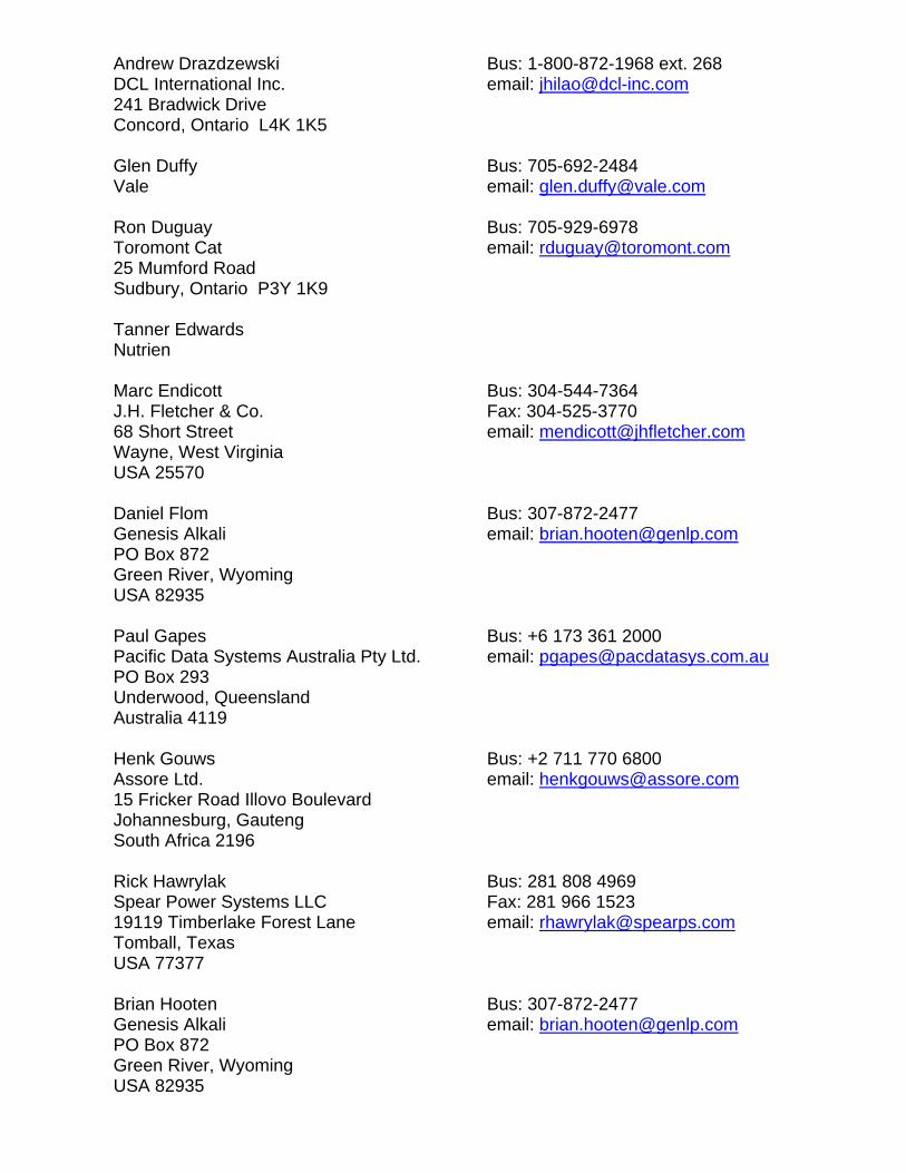
Andrew Drazdzewski Bus: 1-800-872-1968 ext. 268 DCL International Inc. email: [email protected] 241 Bradwick Drive Concord, Ontario L4K 1K5 Glen Duffy Bus: 705-692-2484 Vale email: [email protected] Ron Duguay Bus: 705-929-6978 Toromont Cat email: [email protected] 25 Mumford Road Sudbury, Ontario P3Y 1K9 Tanner Edwards Nutrien Marc Endicott Bus: 304-544-7364 J.H. Fletcher & Co. Fax: 304-525-3770 68 Short Street email: [email protected] Wayne, West Virginia USA 25570 Daniel Flom Bus: 307-872-2477 Genesis Alkali email: [email protected] PO Box 872 Green River, Wyoming USA 82935 Paul Gapes Bus: +6 173 361 2000 Pacific Data Systems Australia Pty Ltd. email: [email protected] PO Box 293 Underwood, Queensland Australia 4119 Henk Gouws Bus: +2 711 770 6800 Assore Ltd. email: [email protected] 15 Fricker Road Illovo Boulevard Johannesburg, Gauteng South Africa 2196 Rick Hawrylak Bus: 281 808 4969 Spear Power Systems LLC Fax: 281 966 1523 19119 Timberlake Forest Lane email: [email protected] Tomball, Texas USA 77377 Brian Hooten Bus: 307-872-2477 Genesis Alkali email: [email protected] PO Box 872 Green River, Wyoming USA 82935
Martin Imbeault Bus: 819-865-7173 Goldcorp email: [email protected] 1751 Davy Road Rouyn-Noranda, Quebec J9Y 0A8 Seppo Karhu Bus: 35 840 077 5939 Sandvik email: [email protected] Vahdointie, Turku Finland 20101 Jussi Koivuniemi Bus: +35 8505950686 Sandvik Mining email: [email protected] Finland Constance Kridiotis Bus: 519-333-7507 Agnico Eagle Mines email: [email protected] 874 Montrose Street Sarnia, Ontario N7T 5B7 Brian Kutschke Bus: 705-675-3381 United Steelworkers Local 6500 email: [email protected] 66 Brady Street Sudbury, Ontario P3E 1C8 Alain Landry email: [email protected] Glencore – Sudbury INO 8 Edison Road Falconbridge, Ontario P0M 1S0 Patrick Lessard Bus: 705-465-5877 Goldcorp email: [email protected] 3175 Hallnor Road, Hwy 101 East Porcupine, Ontario P0N 1C0 Stan Mack Bus: 6 103 222 3295 Johnson Matthey SEC LLC email: [email protected] 900 Forge Avenue, Suite 100 Audubon, Pennsylvania USA 19403 Kevin Mailey Bus: 204-297-4375 Mammoth Equipment and Exhaust Inc. email: [email protected] 107-251 Saultreaux Crescent Winnipeg, Manitoba R3J 3C7 Rob Martel Alamos Gold
Dana Matson Bus: 705-929-3110 Caterpillar email: [email protected] 3700 Steeles Avenue West, Suite 902 Woodbridge, Ontario L4L 8K8 John McLeod Nutrien Travis McNally Bus: 1 306 683 1810 Nutrien email: [email protected] Scott Middleton Bus: 705-427-3051 SSR Mining Inc. email: [email protected] 202-2100 Airport Drive North Saskatoon, Saskatchewan S7L 6M6 Jason Nagy Bus: 514-757-9275 Marindustrial Canada email: [email protected] 715 Jacques-Cartier Road Boucherville, Quebec J4B 6J6 Judit Nelson Bus : 705-692-2151 Vale email : [email protected] Sudbury, Ontario Jan Romo Bus: 705-673-3661 Glencore Fax: 705-673-1183 2550 Richard Lake Road email: [email protected] Sudbury, Ontario P3G 0A3 Brent Rubeli Bus: 613-996-6285 CanmetMINING Fax: 613-996-2597 1 Haanel Drive, Building 9 email: [email protected] Nepean, Ontario K1A 1M1 Kenn Schmitz Bus: 705-222-0300 KES Equipment Inc. email: [email protected] 4 Perini Road Elliot Lake, Ontario P5A 2T1 Micheal Schomer Bus: 775-407-0106 Small Mine Development email: [email protected] 2550 Industrial Way Battle Mountain, Nevada USA 89820 Maliki Setagone Bus: +2 713 230 5329 Assore Ltd. email: [email protected] 15 Fricker Road Illovo Boulevard Johannesburg, Gauteng South Africa 2196
Tanner Smith Bus: 306-257-2138 Nutrien email: [email protected] Allan, Saskatchewan Paul Sparenberg Bus: 313-204-2782 MTU America email: [email protected] 39525 MacKenzie Drive Novi, Michigan USA 48377 Evelynn Stirling Bus: 812-344-6166 Cummins Inc. email: [email protected] 500 Jackson Street Columbus, Indiana USA 47201 Jade Stos Bus: 613-807-8719 Environment and Climate Change Canada email: [email protected] Ottawa, Ontario Camilla Sublett Bus: 647-338-4750 Barrick Gold email: [email protected] Toronto, Ontario Karsten Taudte Bus: 49 615 217 4187 Cummins Inc. email: [email protected] Peter-Traiser-Sttrasse 1 Gross Gerau Germany 64521 Troy Terrillion Bus: 775-778-2149 Newmount USA Limited email: [email protected] 1655 Mountain City Highway Elko, Nevada USA 89801 Greg Tremaine Bus: 678-356-1224 DEUTZ Corporation email: [email protected] 3883 Steve Reynolds Boulevard Norcross, Georgia, USA Hal Walls Bus: 775-300-9055 MineTerra email: [email protected] One East Liberty Street Suite 600 Reno, Nevada USA 89501 Kevin Watson Bus: 705-682-8825 Vale email: [email protected] Sudbury, Ontario
Nicole Webb Bus: 306-933-8679 Nutrien 122 1st Avenue South, Suite 500 Saskatoon, Saskatchewan S7K 7G3 Bob Wilford Bus: 416-574-9908 Wajax Fax: 406-259-1863 10 Diesel Drive email: [email protected] Toronto, Ontario M8W 2T8 Vance Ylioja Bus: 306-867-7057 Nutrien email: [email protected] Saskatoon, Saskatchewan David Young Bus: 613-943-9264 CanmetMINING email: [email protected] 1 Haanel Drive, Building 9 Ottawa, Ontario K1A 1M1
MDEC 2018 WORKSHOP
1
Overview Of Automotive xEV Markets and Vehicle Electrification
Bapi Surampudi, Ph.D.
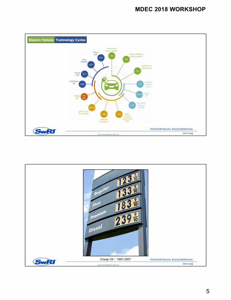
Brief History of Vehicle Electrification
2
MDEC 2018 WORKSHOP
2
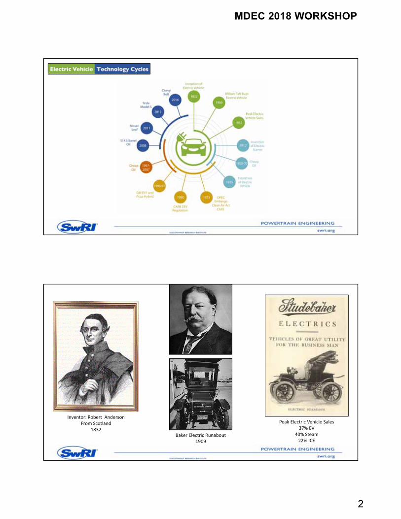
Baker Electric Runabout1909
Inventor: Robert AndersonFrom Scotland
1832
Peak Electric Vehicle Sales37% EV
40% Steam22% ICE
MDEC 2018 WORKSHOP
3
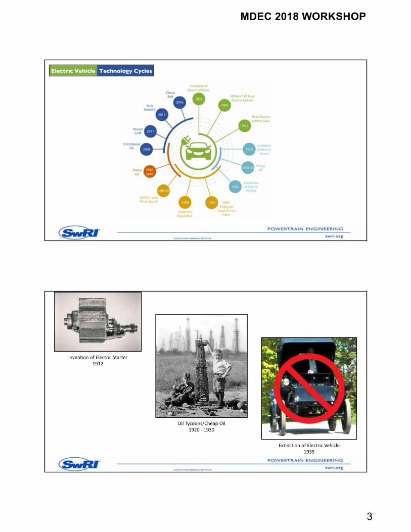
Invention of Electric Starter1912
Oil Tycoons/Cheap Oil1920 ‐ 1930
Extinction of Electric Vehicle1935
MDEC 2018 WORKSHOP
4
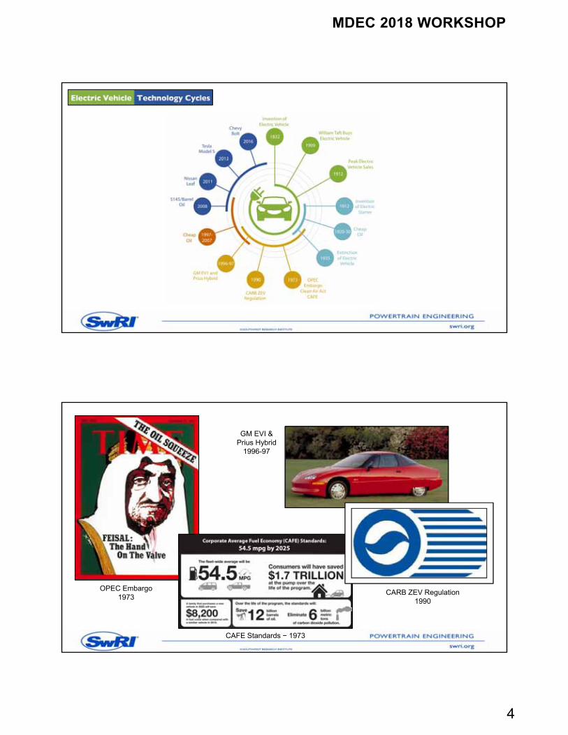
OPEC Embargo1973
CAFE Standards − 1973
GM EVI &Prius Hybrid
1996-97
CARB ZEV Regulation1990
MDEC 2018 WORKSHOP
5
Cheap Oil − 1997-2007
MDEC 2018 WORKSHOP
6
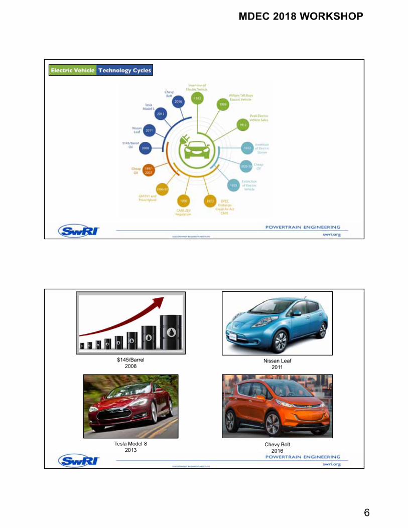
Nissan Leaf2011
Tesla Model S2013
Chevy Bolt2016
$145/Barrel2008
MDEC 2018 WORKSHOP
7
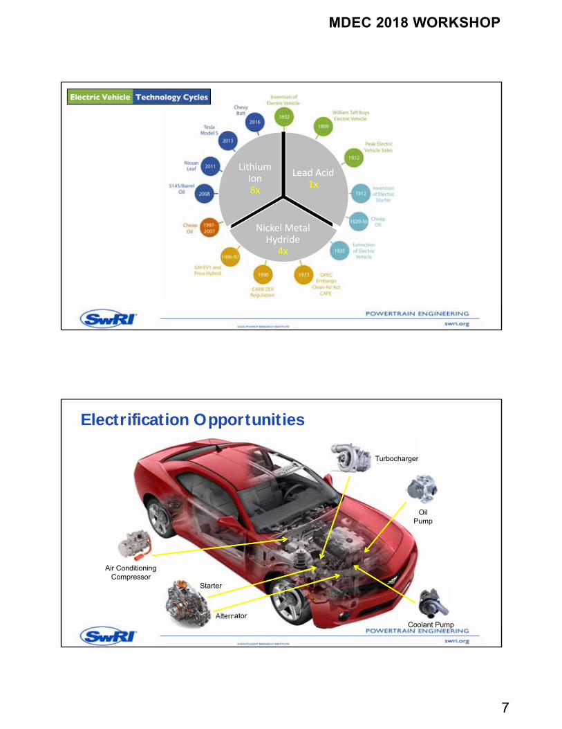
Lithium Ion8x
Lead Acid1x
Nickel Metal Hydride
4x
Electrification Opportunities
Turbocharger
Coolant Pump
OilPump
Alternator
Air ConditioningCompressor
Starter
MDEC 2018 WORKSHOP
8
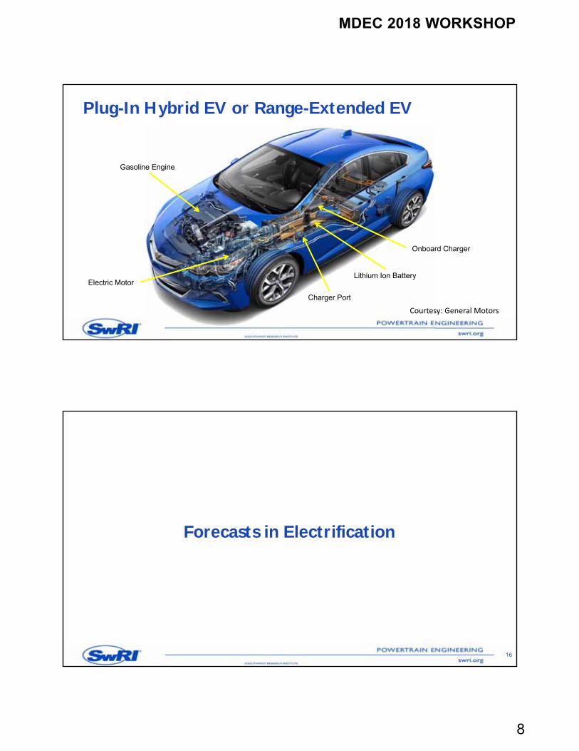
Plug-In Hybrid EV or Range-Extended EV
Lithium Ion Battery
Charger Port
Onboard Charger
Electric Motor
Gasoline Engine
Courtesy: General Motors
Forecasts in Electrification
16
MDEC 2018 WORKSHOP
9
OEM Electric Car Announcements
BMW – have 15-25% of BMW group’s sales be all electric and 25 electrified vehicles by 2025 Daimler – 0.1 million annual electric car sales by 2020 VW – 2-3 million annual electric car sales by 2025 Ford – 13 new EV models by 2020 Honda – 2/3 of 2030 sales be HEVs, PHEVs, BEVs and FCEVs Renault-Nissan – 1.5 million cumulative annual electric car sales by 2020 Volvo – 1 million cumulative electric car sales by 2025 Tesla – 1 million annual electric car sales by 2020
17
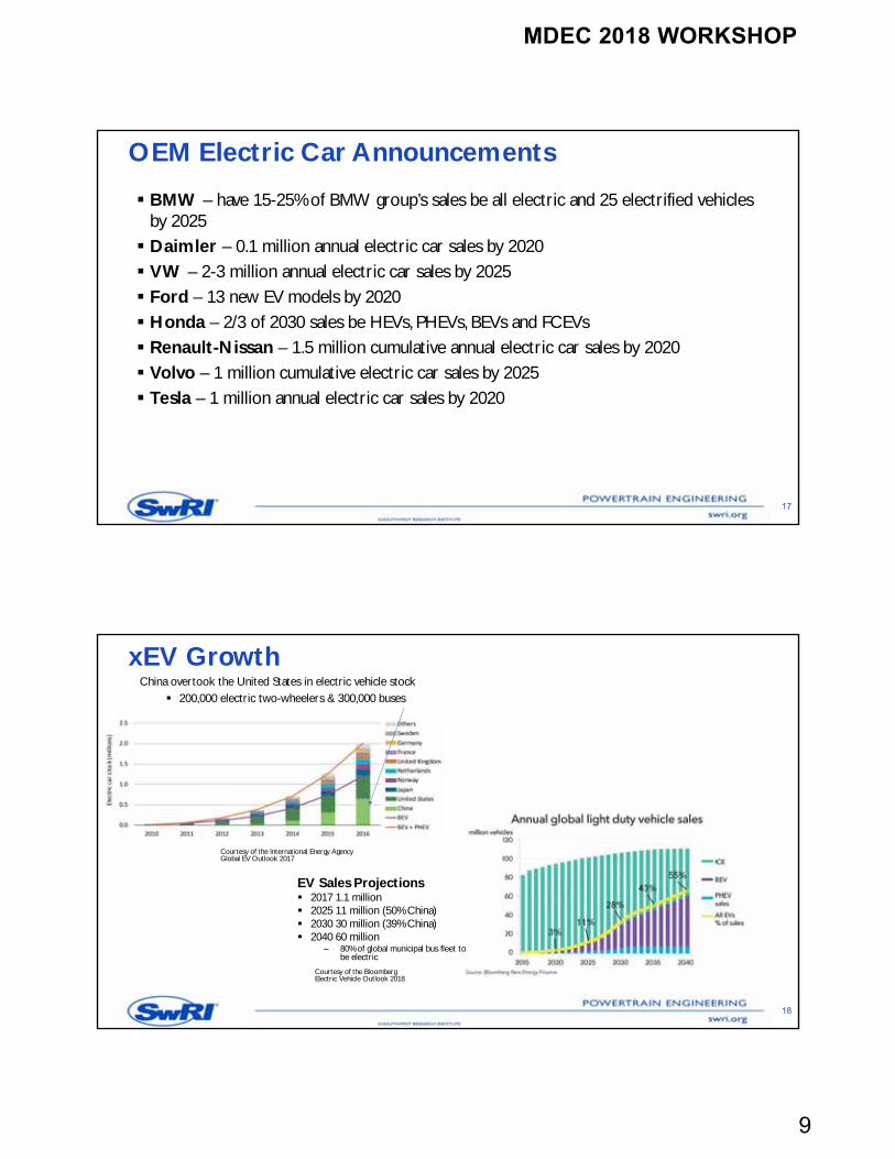
xEV Growth
18
Courtesy of the International Energy Agency Global EV Outlook 2017
China overtook the United States in electric vehicle stock 200,000 electric two-wheelers & 300,000 buses
Courtesy of the Bloomberg Electric Vehicle Outlook 2018
EV Sales Projections 2017 1.1 million 2025 11 million (50% China) 2030 30 million (39% China) 2040 60 million
– 80% of global municipal bus fleet to be electric
MDEC 2018 WORKSHOP
10
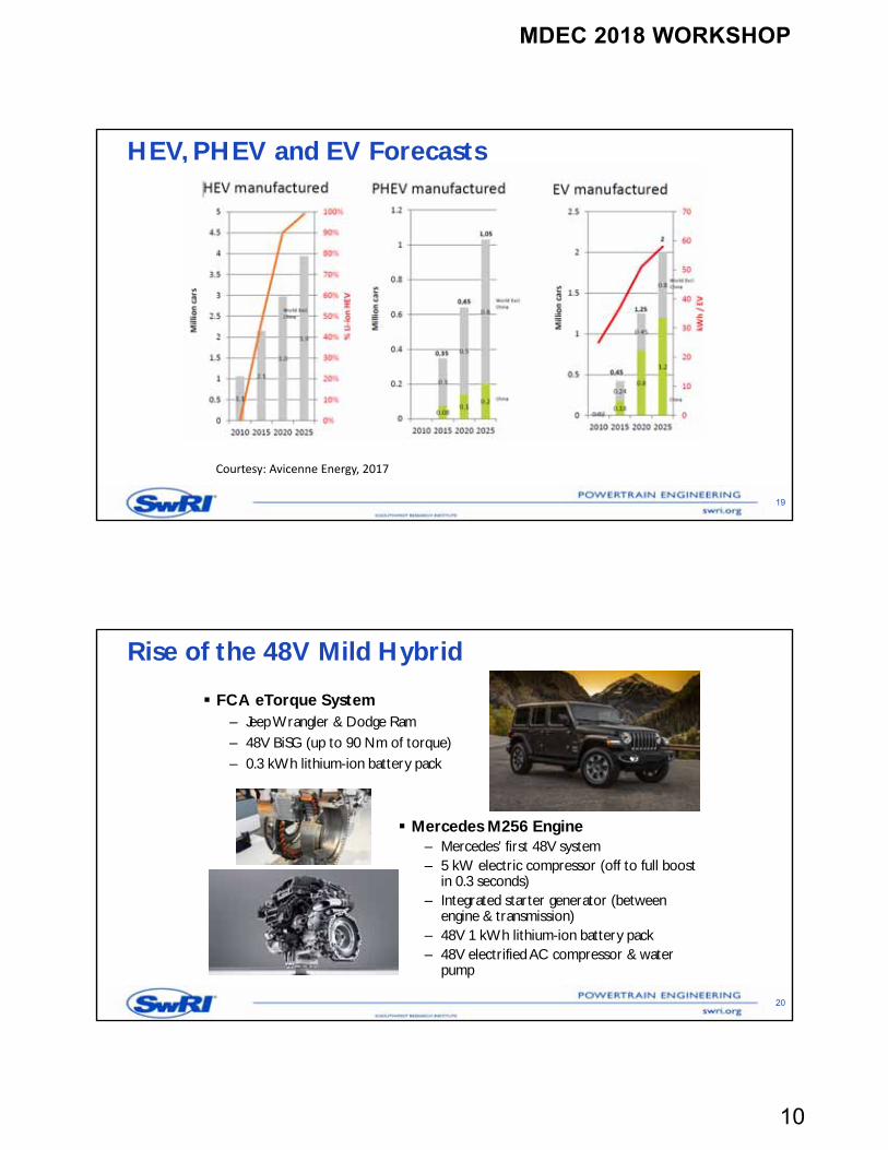
HEV, PHEV and EV Forecasts
19
Courtesy: Avicenne Energy, 2017
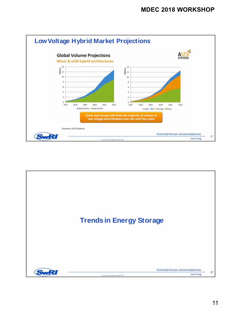
Rise of the 48V Mild Hybrid
20
FCA eTorque System– Jeep Wrangler & Dodge Ram– 48V BiSG (up to 90 Nm of torque)– 0.3 kWh lithium-ion battery pack
Mercedes M256 Engine– Mercedes’ first 48V system– 5 kW electric compressor (off to full boost
in 0.3 seconds)– Integrated starter generator (between
engine & transmission)– 48V 1 kWh lithium-ion battery pack– 48V electrified AC compressor & water
pump
MDEC 2018 WORKSHOP
11
21
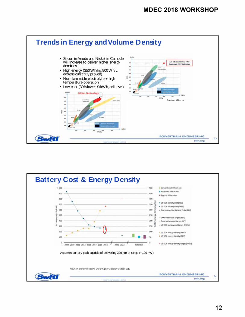
Courtesy: A123 Systems
Low Voltage Hybrid Market Projections
Trends in Energy Storage
22
MDEC 2018 WORKSHOP
12
Trends in Energy and Volume Density
Silicon in Anode and Nickel in Cathode will increase to deliver higher energy densities
High energy (350 Wh/kg, 800 Wh/L designs currently proven)
Non-flammable electrolyte + high temperature operation
Low cost (30% lower $/kWh, cell level)
23
Courtesy: SilLion Inc
Battery Cost & Energy Density
Courtesy of the International Energy Agency Global EV Outlook 2017
24
Assumes battery pack capable of delivering 320 km of range (~100 kW)
MDEC 2018 WORKSHOP
13
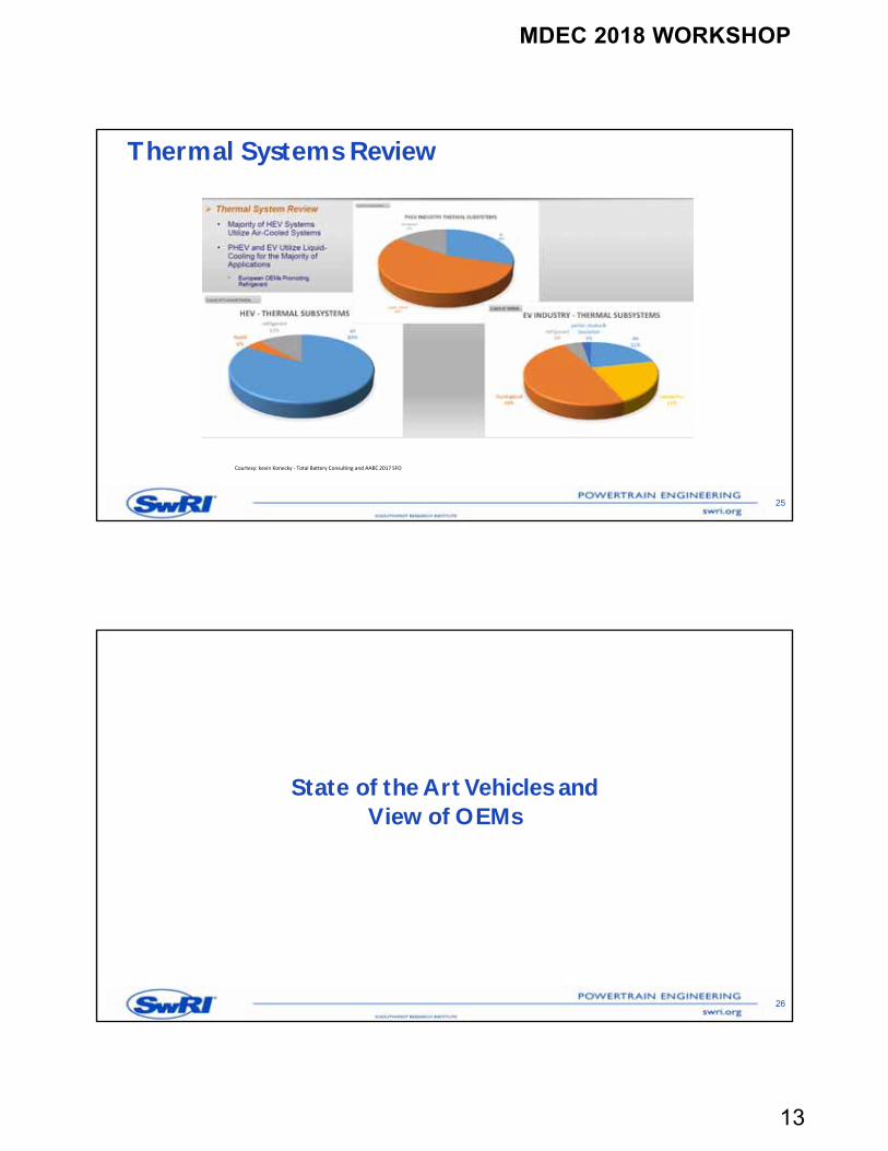
Thermal Systems Review
25
Courtesy: kevin Konecky ‐ Total Battery Consulting and AABC 2017 SFO
State of the Art Vehicles andView of OEMs
26
MDEC 2018 WORKSHOP
14
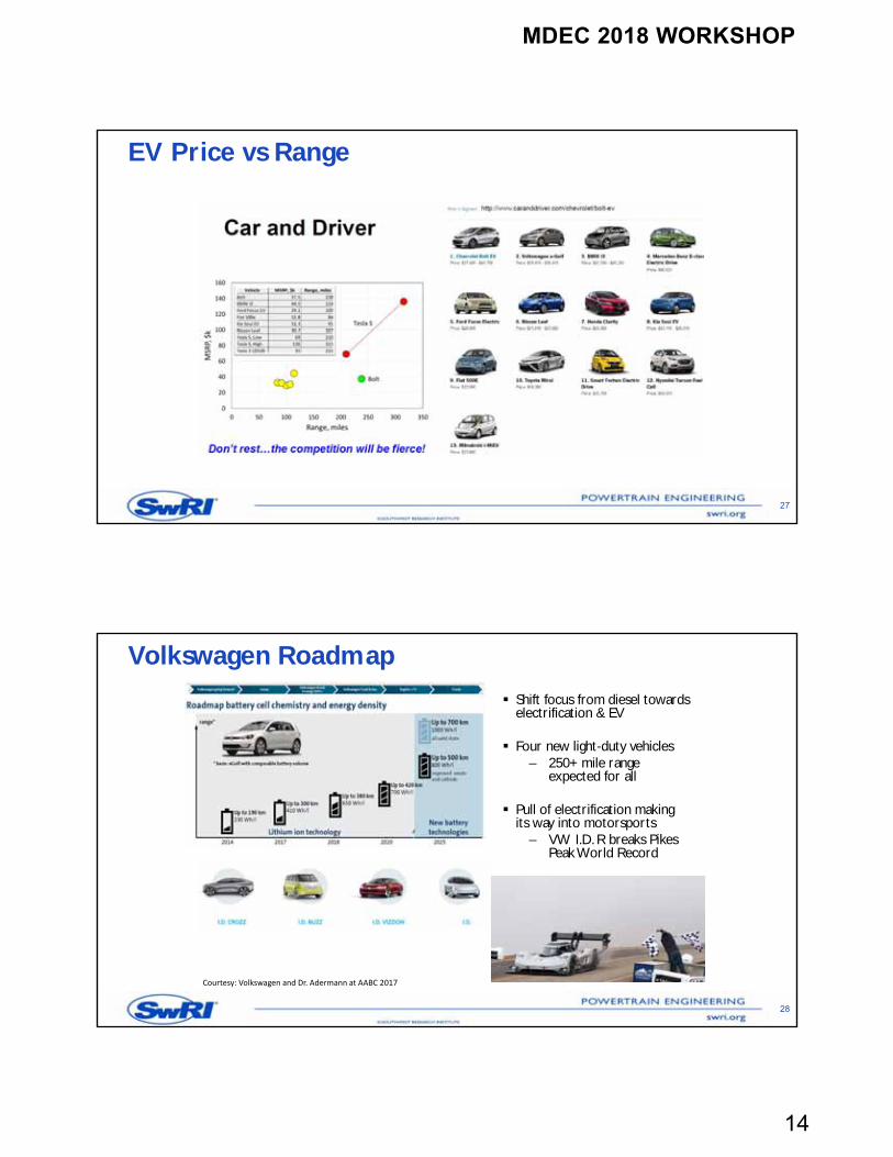
EV Price vs Range
27
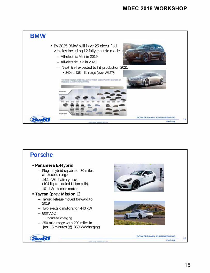
Courtesy: Volkswagen and Dr. Adermann at AABC 2017
Volkswagen Roadmap
28
Shift focus from diesel towards electrification & EV
Four new light-duty vehicles– 250+ mile range
expected for all
Pull of electrification making its way into motorsports
– VW I.D. R breaks Pikes Peak World Record
MDEC 2018 WORKSHOP
15
BMW
By 2025 BMW will have 25 electrifiedvehicles including 12 fully electric models
– All-electric Mini in 2019– All-electric iX3 in 2020– iNext & i4 expected to hit production 2021
• 340 to 435 mile range (over WLTP)
29
Porsche
Panamera E-Hybrid– Plug-in hybrid capable of 30 miles
all-electric range– 14.1 kWh battery pack
(104 liquid-cooled Li-Ion cells)– 101 kW electric motor
Taycan (prev. Mission E)– Target release moved forward to
2019– Two electric motors for 440 kW– 800 VDC
• Inductive charging– 250 mile range with 200 miles in
just 15 minutes (@ 350 kWcharging)
30
MDEC 2018 WORKSHOP
16
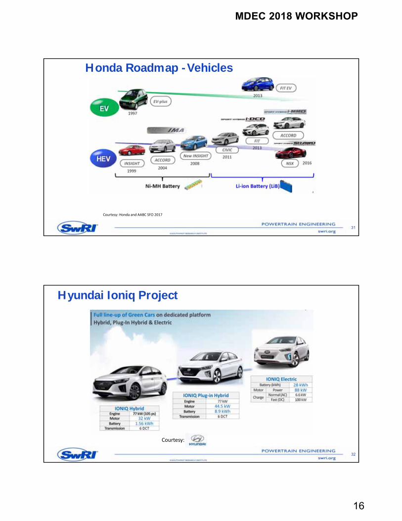
Honda Roadmap -Vehicles
31
Courtesy: Honda and AABC SFO 2017
Hyundai Ioniq Project
32
Courtesy:
MDEC 2018 WORKSHOP
17
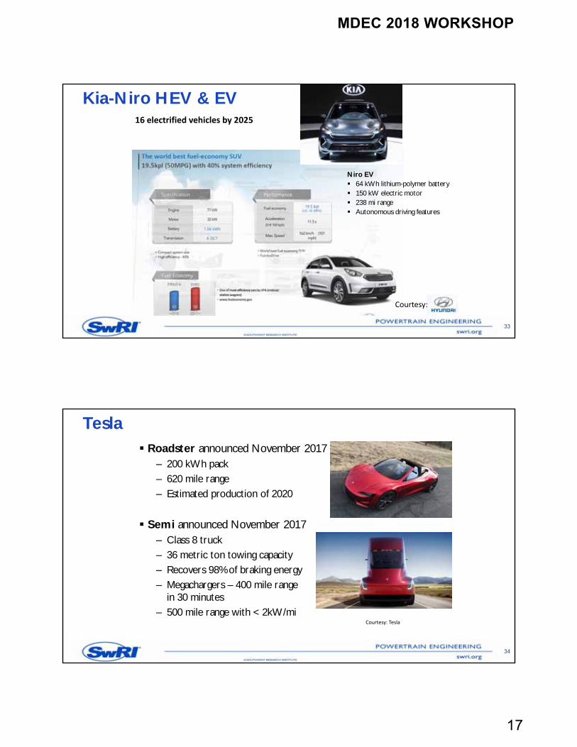
Kia-Niro HEV & EV
33
Courtesy:
Niro EV 64 kWh lithium-polymer battery 150 kW electric motor 238 mi range Autonomous driving features
16 electrified vehicles by 2025
Roadster announced November 2017– 200 kWh pack – 620 mile range– Estimated production of 2020
Semi announced November 2017– Class 8 truck– 36 metric ton towing capacity– Recovers 98% of braking energy– Megachargers – 400 mile range
in 30 minutes– 500 mile range with < 2kW/mi
Tesla
34
Courtesy: Tesla
MDEC 2018 WORKSHOP
18
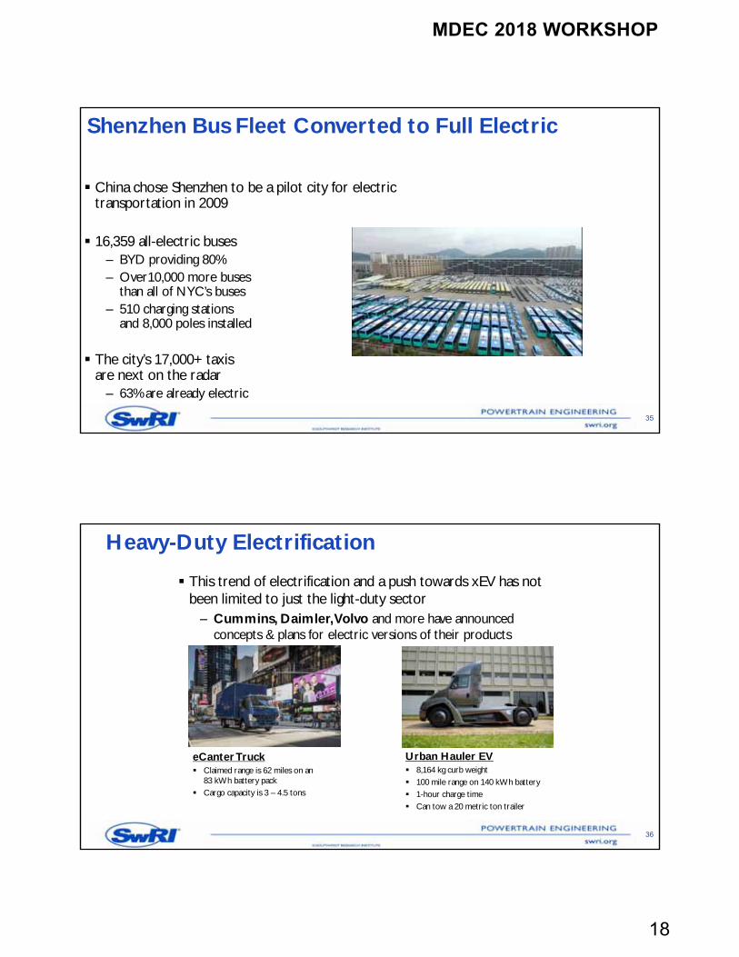
Shenzhen Bus Fleet Converted to Full Electric
35
China chose Shenzhen to be a pilot city for electric transportation in 2009
16,359 all-electric buses– BYD providing 80%– Over10,000 more buses
than all of NYC’s buses– 510 charging stations
and 8,000 poles installed
The city’s 17,000+ taxis are next on the radar
– 63% are already electric
Heavy-Duty Electrification
This trend of electrification and a push towards xEV has not been limited to just the light-duty sector
– Cummins, Daimler, Volvo and more have announced concepts & plans for electric versions of their products
36
eCanterTruck Claimed range is 62 miles on an
83 kWh battery pack Cargo capacity is 3 – 4.5 tons
Urban Hauler EV 8,164 kg curb weight 100 mile range on 140 kWh battery 1-hour charge time Can tow a 20 metric ton trailer
MDEC 2018 WORKSHOP
19
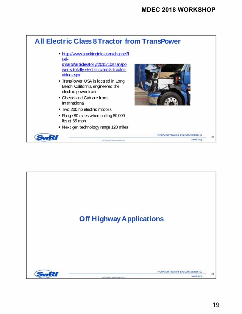
All Electric Class 8 Tractor from TransPower
http://www.truckinginfo.com/channel/fuel-smarts/article/story/2015/10/transpower-s-totally-electric-class-8-tractor-video.aspx TransPower USA is located in Long
Beach, California, engineered the electric powertrain Chassis and Cab are from
International Two 200 hp electric mtoors Range 80 miles when pulling 80,000
lbs at 65 mph Next gen technology range 120 miles
37
Off Highway Applications
38
MDEC 2018 WORKSHOP
20
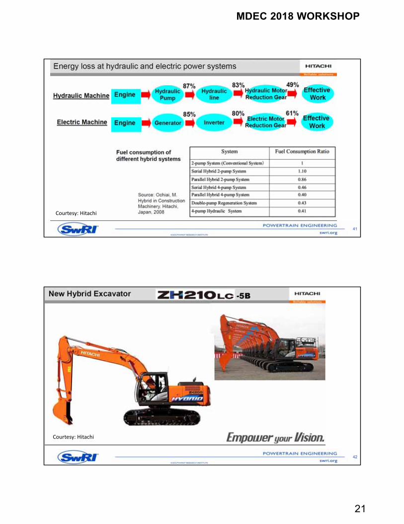
39
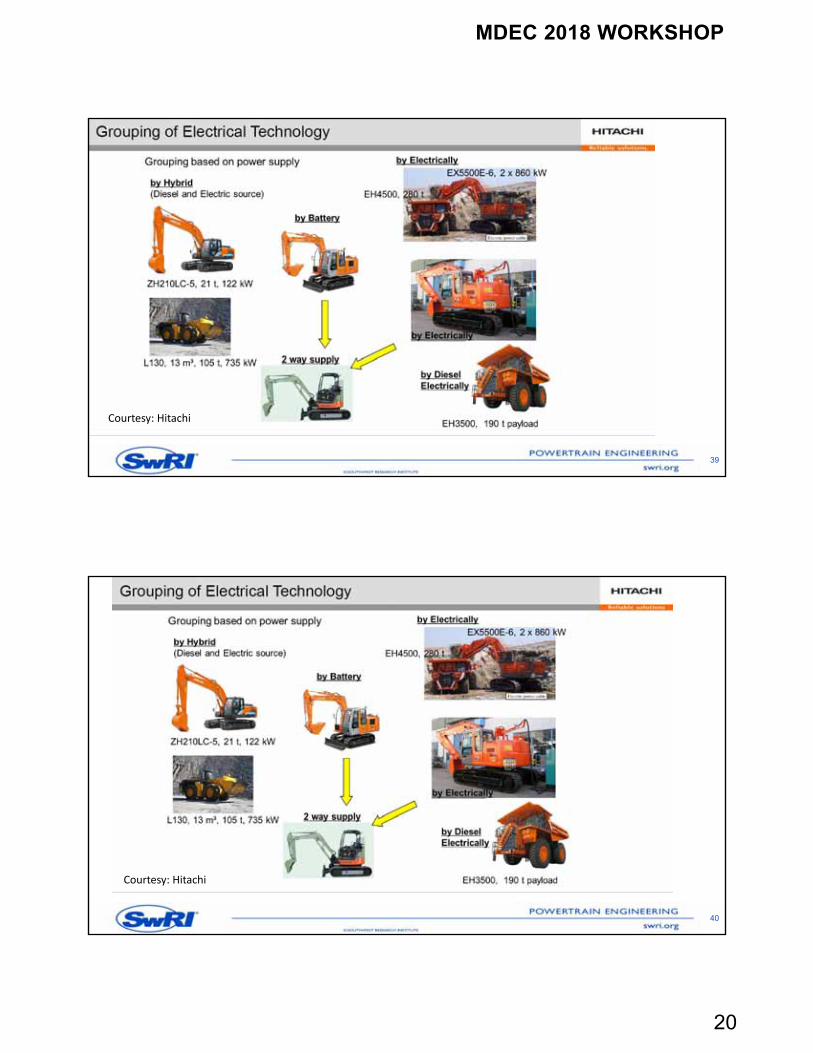
Courtesy: Hitachi
40
Courtesy: Hitachi
MDEC 2018 WORKSHOP
21
41
Courtesy: Hitachi
42
Courtesy: Hitachi
MDEC 2018 WORKSHOP
22
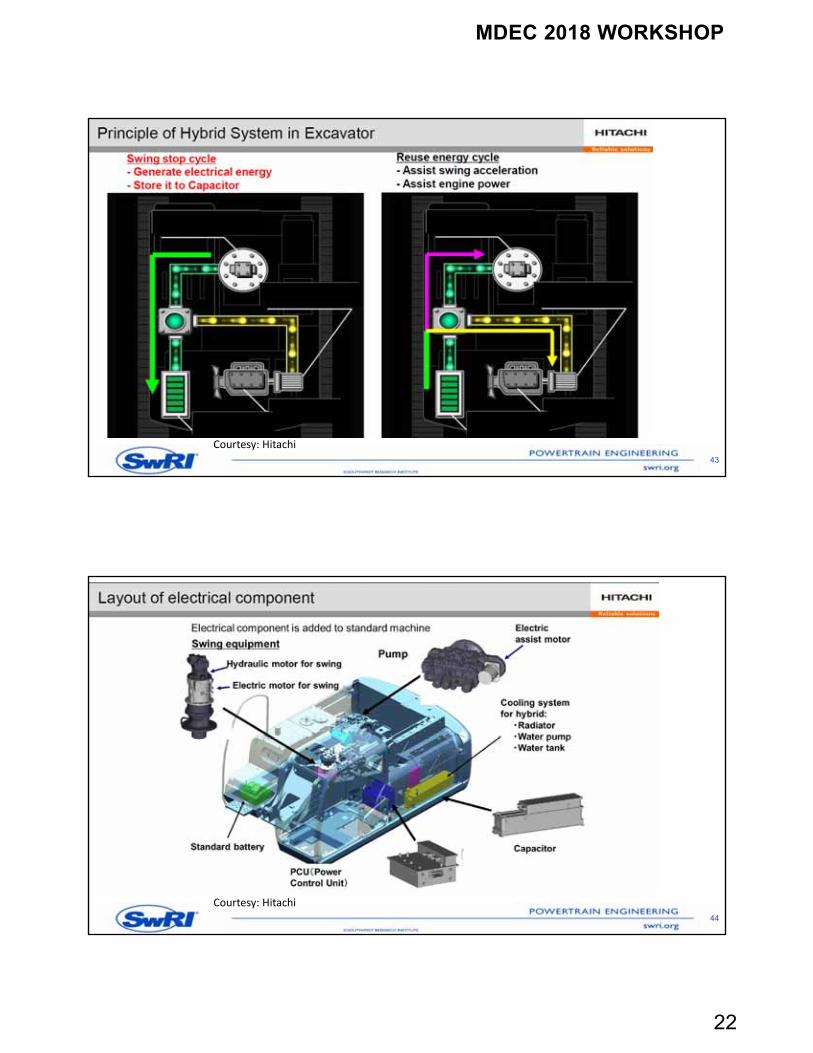
43
Courtesy: Hitachi
44
Courtesy: Hitachi
MDEC 2018 WORKSHOP
23
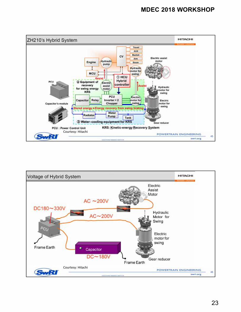
45
Courtesy: Hitachi
46
Courtesy: Hitachi
MDEC 2018 WORKSHOP
24
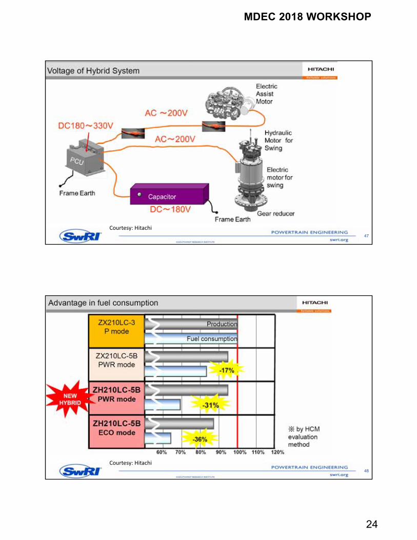
47
Courtesy: Hitachi
48
Courtesy: Hitachi
MDEC 2018 WORKSHOP
25
49
Courtesy: Hitachi
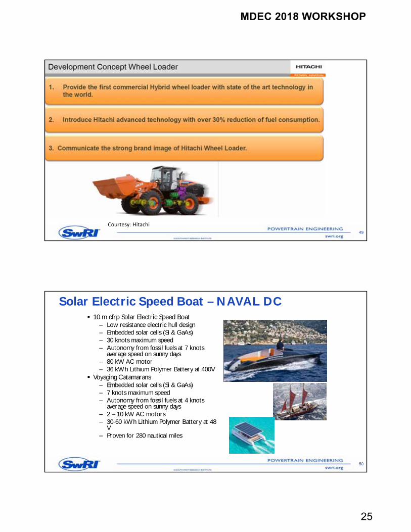
Solar Electric Speed Boat – NAVAL DC 10 m cfrp Solar Electric Speed Boat
– Low resistance electric hull design– Embedded solar cells (Si & GaAs)– 30 knots maximum speed– Autonomy from fossil fuels at 7 knots
average speed on sunny days– 80 kW AC motor– 36 kWh Lithium Polymer Battery at 400V
Voyaging Catamarans– Embedded solar cells (Si & GaAs)– 7 knots maximum speed– Autonomy from fossil fuels at 4 knots
average speed on sunny days– 2 – 10 kW AC motors– 30-60 kWh Lithium Polymer Battery at 48
V– Proven for 280 nautical miles
50
MDEC 2018 WORKSHOP
26
NAVAL DC Lithium Polymer Battery Packs
48 V 15.5 kWh to 800 V 2MWh
51
Integrated On Board Chargers
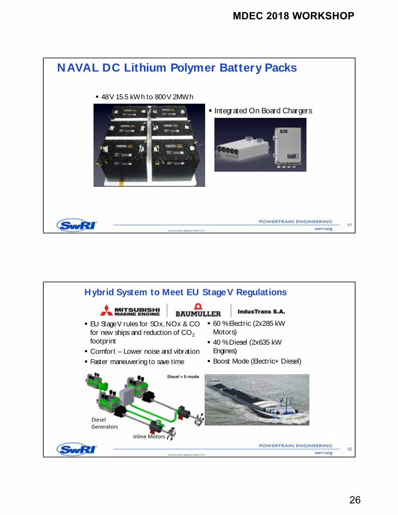
Hybrid System to Meet EU Stage V Regulations
EU Stage V rules for SOx, NOx & CO for new ships and reduction of CO2footprint Comfort – Lower noise and vibration Faster maneuvering to save time
52
60 % Electric (2x285 kW Motors) 40 % Diesel (2x635 kW
Engines) Boost Mode (Electric+ Diesel)
DieselGenerators
Inline Motors
MDEC 2018 WORKSHOP
27
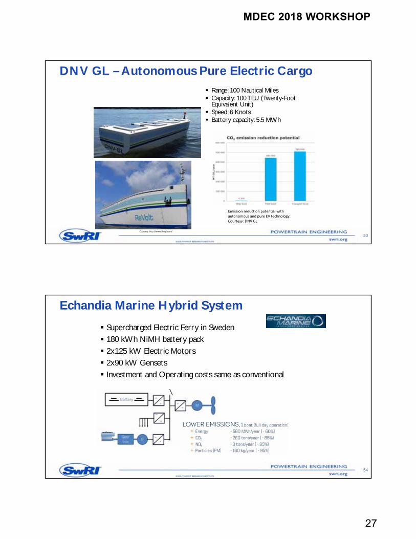
DNV GL – Autonomous Pure Electric Cargo Range: 100 Nautical Miles Capacity: 100 TEU (Twenty-Foot
Equivalent Unit) Speed: 6 Knots Battery capacity: 5.5 MWh
53
Emission reduction potential with autonomous and pure EV technology:Courtesy: DNV GL
Courtesy: http://www.dnvgl.com/
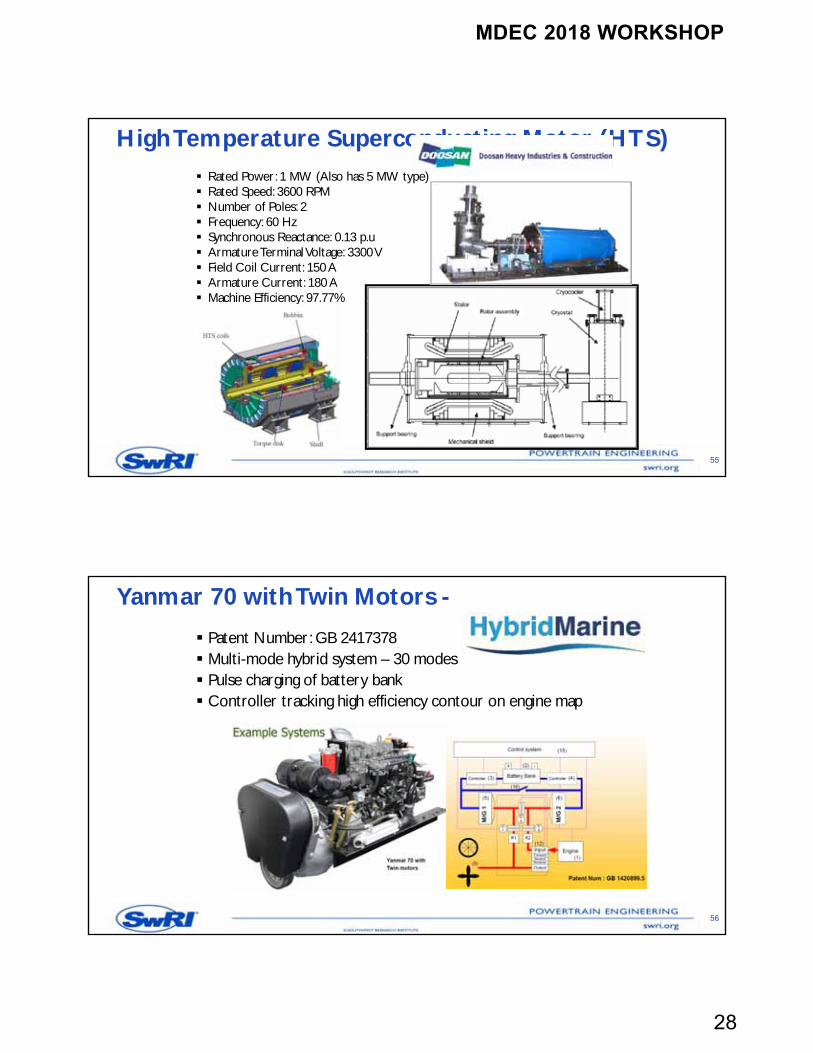
Echandia Marine Hybrid System
Supercharged Electric Ferry in Sweden 180 kWh NiMH battery pack 2x125 kW Electric Motors 2x90 kW Gensets Investment and Operating costs same as conventional
54
MDEC 2018 WORKSHOP
28
High Temperature Superconducting Motor (HTS) Rated Power: 1 MW (Also has 5 MW type) Rated Speed: 3600 RPM Number of Poles: 2 Frequency: 60 Hz Synchronous Reactance: 0.13 p.u Armature Terminal Voltage: 3300 V Field Coil Current: 150 A Armature Current: 180 A Machine Efficiency: 97.77%
55
Yanmar 70 with Twin Motors -
Patent Number: GB 2417378 Multi-mode hybrid system – 30 modes Pulse charging of battery bank Controller tracking high efficiency contour on engine map
56
MDEC 2018 WORKSHOP
29
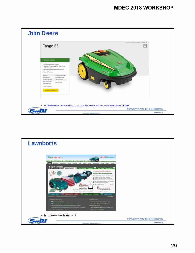
John Deere
http://www.deere.com/wps/dcom/en_INT/products/equipment/autonomous_mower/tango_e5/tango_e5.page
Lawnbotts
http://www.lawnbotts.com/
MDEC 2018 WORKSHOP
30
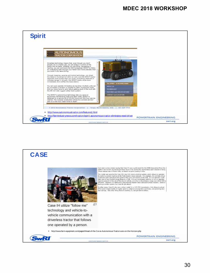
Spirit
http://www.autonomoustractor.com/features1.html http://farmindustrynews.com/tractors/spirit-autonomous-tractor-eliminates-need-driver
CASE
http://www.farm-equipment.com/pages/Ahead-of-the-Curve-Autonomous-Tractors-are-on-the-Horizon.php
MDEC 2018 WORKSHOP
31
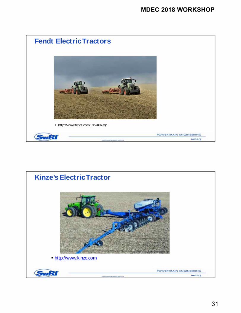
Fendt Electric Tractors
http://www.fendt.com/us/2466.asp
Kinze’s Electric Tractor
http://www.kinze.com
MDEC 2018 WORKSHOP
32
Summary
Global sales of xEVs continue to increase– China leading the way in BEV (buses and small vehicles)
HEVs & EVs forecast to be commonplace among OEM offerings come 2025– Tesla aim for 1 million cumulative EV sales by 2020– VW aim for 2-3 million annual EV sales by 2025
HEV and EV not limited to light-duty– Tesla & Cummins announce EV semi
Battery voltage increasing– Porsche Mission E will use 800 V battery system
63
Summary …
Electrification of off highway and marine machinery is primary driven by emission regulation, comfort and efficiency considerations All off highway OEMs are in the process of developing new electric versions of their
products Standards and regulations in the electric and battery system area are in early stages
of development with several working committees As battery prices decreases manufacturers are preparing to meet impending volume
production opportunities
64
MDEC 2018 WORKSHOP
33
Overview of fundamentals and state of the art Lithium Ion Cells
Bapi Surampudi, Ph.D.
Overview
66
MDEC 2018 WORKSHOP
34
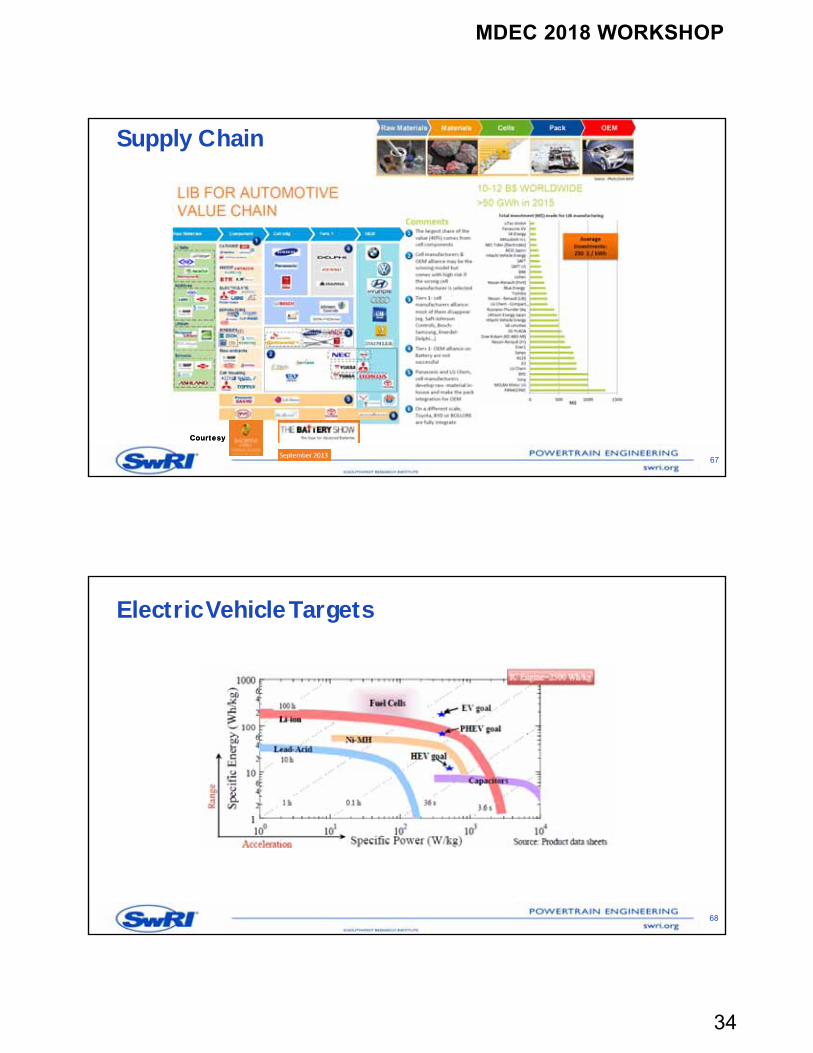
Supply Chain
67
CourtesyCourtesy
Electric Vehicle Targets
68
MDEC 2018 WORKSHOP
35
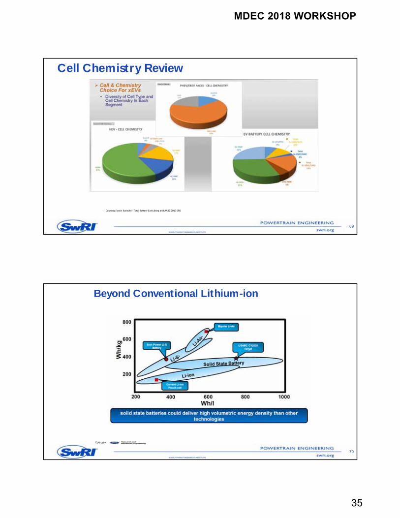
Cell Chemistry Review
69
Courtesy: kevin Konecky ‐ Total Battery Consulting and AABC 2017 SFO
Beyond Conventional Lithium-ion
70
Courtesy:
MDEC 2018 WORKSHOP
36
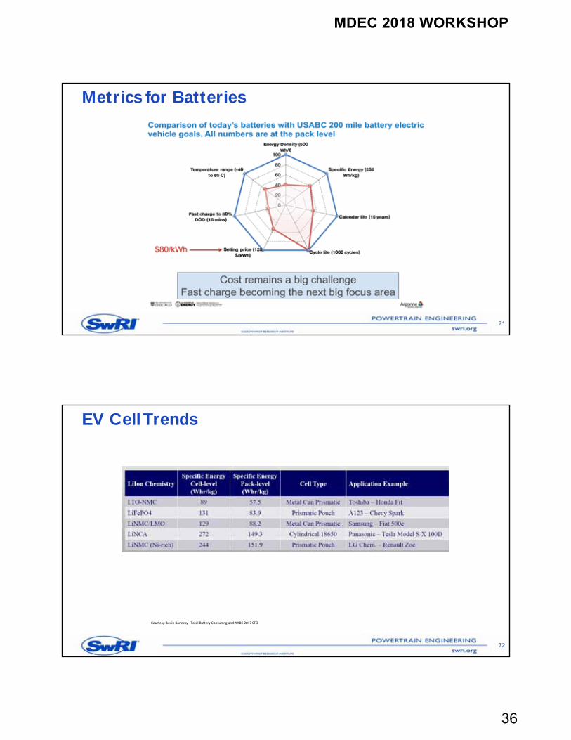
Metrics for Batteries
71
EV Cell Trends
72
Courtesy: kevin Konecky ‐ Total Battery Consulting and AABC 2017 SFO
MDEC 2018 WORKSHOP
37
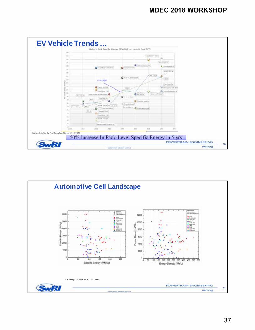
EV Vehicle Trends …
73
Courtesy: kevin Konecky ‐ Total Battery Consulting and AABC 2017 SFO
Automotive Cell Landscape
74
Courtesy: JM and AABC SFO 2017
MDEC 2018 WORKSHOP
38
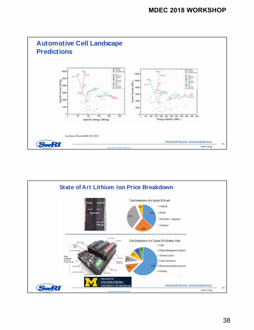
Automotive Cell Landscape Predictions
75
Courtesy: JM and AABC SFO 2017
State of Art Lithium Ion Price Breakdown
76
MDEC 2018 WORKSHOP
39
Working Principles of a Lithium Ion Cell
77
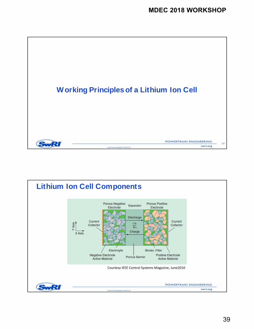
Lithium Ion Cell Components
Courtesy IEEE Control Systems Magazine, June2010
MDEC 2018 WORKSHOP
40
Lithium Ion Cell Components …
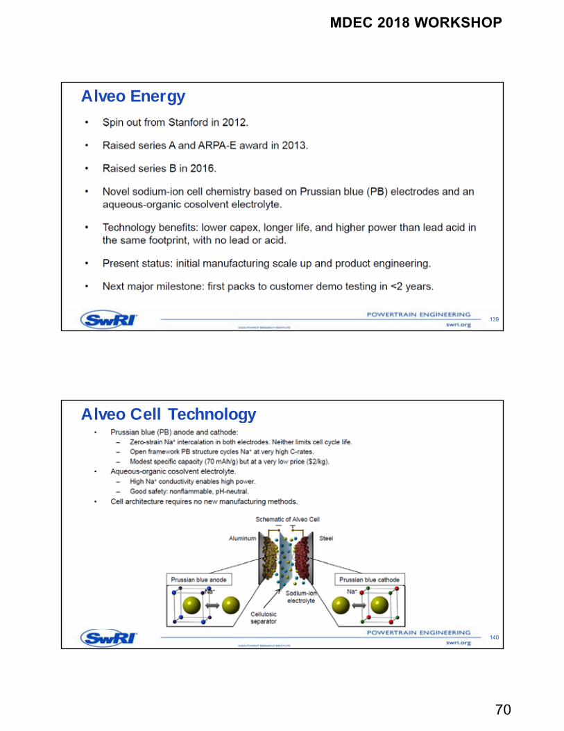
A porous negative electrode of a Li-ion cell is connected to the negative terminal of the cell. This electrode usually contains graphite, which is an intercalation material A porous positive electrode is connected to the positive terminal of the cell. The
positive electrode can be comprised of various chemistries, but it is usually a metal oxide or a blend of multiple metal oxides, such as LixMn2O4 and LixCoO2
A separator is a thin porous medium that separates the negative from the positive electrode. The separator is an electrical insulator that does not allow electrons to flow between the positive and negative electrodes. However, being porous, the separator allows ions to pass through it by means of the electrolyte The electrolyte is a concentrated solution that contains charged species. These
charged species can move in response to an electrochemical potential gradient. Note that some Li-ion batteries have a solid electrolyte, which serves both as an ionic conducting medium and an electronically insulating separator
Working Principle of a Lithium Ion Battery
The process of moving ions in and out of an interstitial site in a lattice is called intercalation Both electrodes have lattice sites that can store lithium Charging (discharging) causes the Li ions to leave the lattice sites in the positive
(negative) electrode and enter the lattice sites of the negative (positive) electrode The difference in energy states of the intercalated lithium in the positive and negative
electrodes governs the energy stored in the Li-ion cell Each Lithium-Ion cell has a typical operating voltage that is subset or in between 2.0 V
and 4.2 V The actual cell voltage depends on State of Charge (SOC) Temperatures variations and change in rate of charging compared to recommended
rate will deteriorate the cells
MDEC 2018 WORKSHOP
41
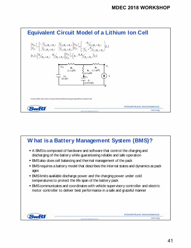
Equivalent Circuit Model of a Lithium Ion Cell
Courtesy NREL http://www.nrel.gov/vehiclesandfuels/energystorage/pdfs/evs17paper2.pdf
What is a Battery Management System (BMS)?
A BMS is composed of hardware and software that control the charging and discharging of the battery while guaranteeing reliable and safe operation BMS also does cell balancing and thermal management of the pack BMS requires a battery model that describes the internal states and dynamics as pack
ages BMS limits available discharge power and the charging power under cold
temperatures to protect the life span of the battery pack BMS communicates and coordinates with vehicle supervisory controller and electric
motor controller to deliver best performance in a safe and graceful manner
MDEC 2018 WORKSHOP
42
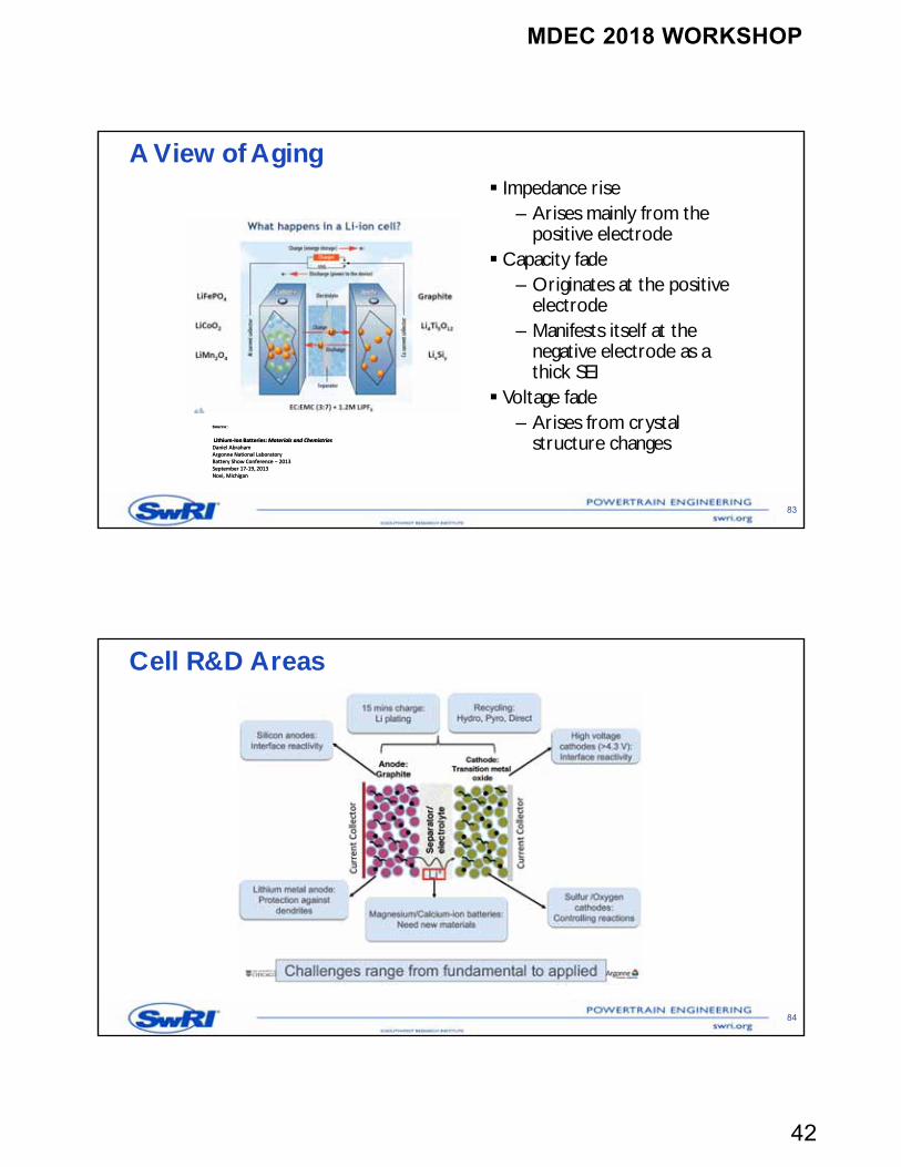
A View of Aging
83
Impedance rise– Arises mainly from the
positive electrode Capacity fade
– Originates at the positive electrode
– Manifests itself at the negative electrode as a thick SEI
Voltage fade – Arises from crystal
structure changesSource:
Lithium‐Ion Batteries: Materials and Chemistries Daniel Abraham Argonne National Laboratory Ba ery Show Conference − 2013 September 17‐19, 2013 Novi, Michigan
Source:
Lithium‐Ion Batteries: Materials and Chemistries Daniel Abraham Argonne National Laboratory Ba ery Show Conference − 2013 September 17‐19, 2013 Novi, Michigan
Cell R&D Areas
84
MDEC 2018 WORKSHOP
43
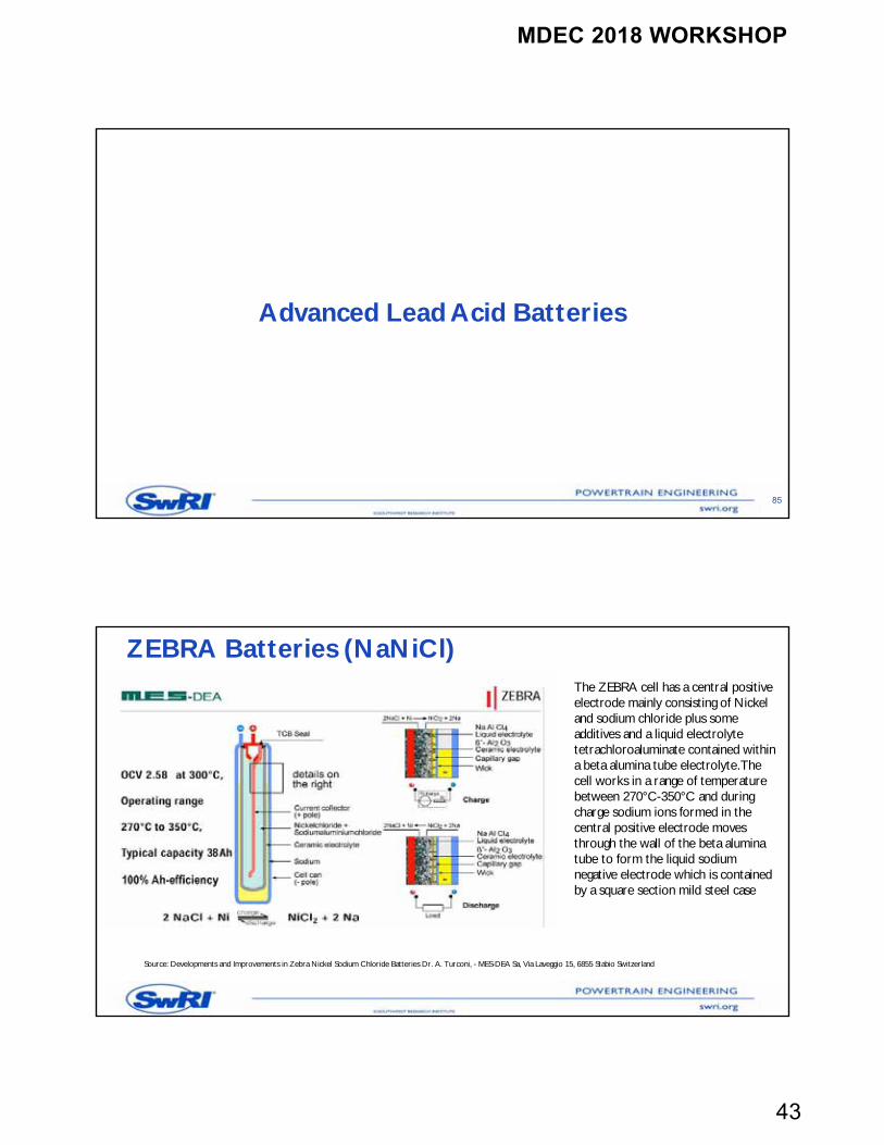
Advanced Lead Acid Batteries
85
ZEBRA Batteries (NaNiCl)The ZEBRA cell has a central positive electrode mainly consisting of Nickel and sodium chloride plus some additives and a liquid electrolyte tetrachloroaluminate contained within a beta alumina tube electrolyte. The cell works in a range of temperature between 270°C-350°C and during charge sodium ions formed in the central positive electrode moves through the wall of the beta alumina tube to form the liquid sodium negative electrode which is contained by a square section mild steel case
Source: Developments and Improvements in Zebra Nickel Sodium Chloride Batteries Dr. A. Turconi, - MES-DEA Sa, Via Laveggio 15, 6855 Stabio Switzerland
MDEC 2018 WORKSHOP
44
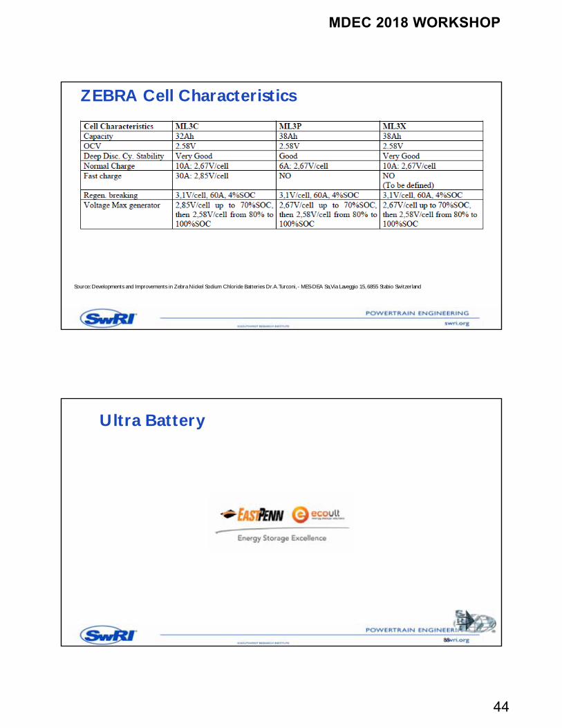
ZEBRA Cell Characteristics
Source: Developments and Improvements in Zebra Nickel Sodium Chloride Batteries Dr. A. Turconi, - MES-DEA Sa, Via Laveggio 15, 6855 Stabio Switzerland
Ultra Battery
88
MDEC 2018 WORKSHOP
45
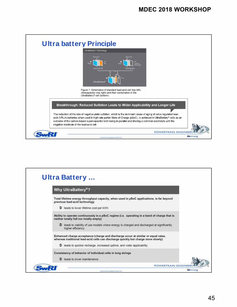
Ultra battery Principle
89
Ultra Battery …
90
MDEC 2018 WORKSHOP
46
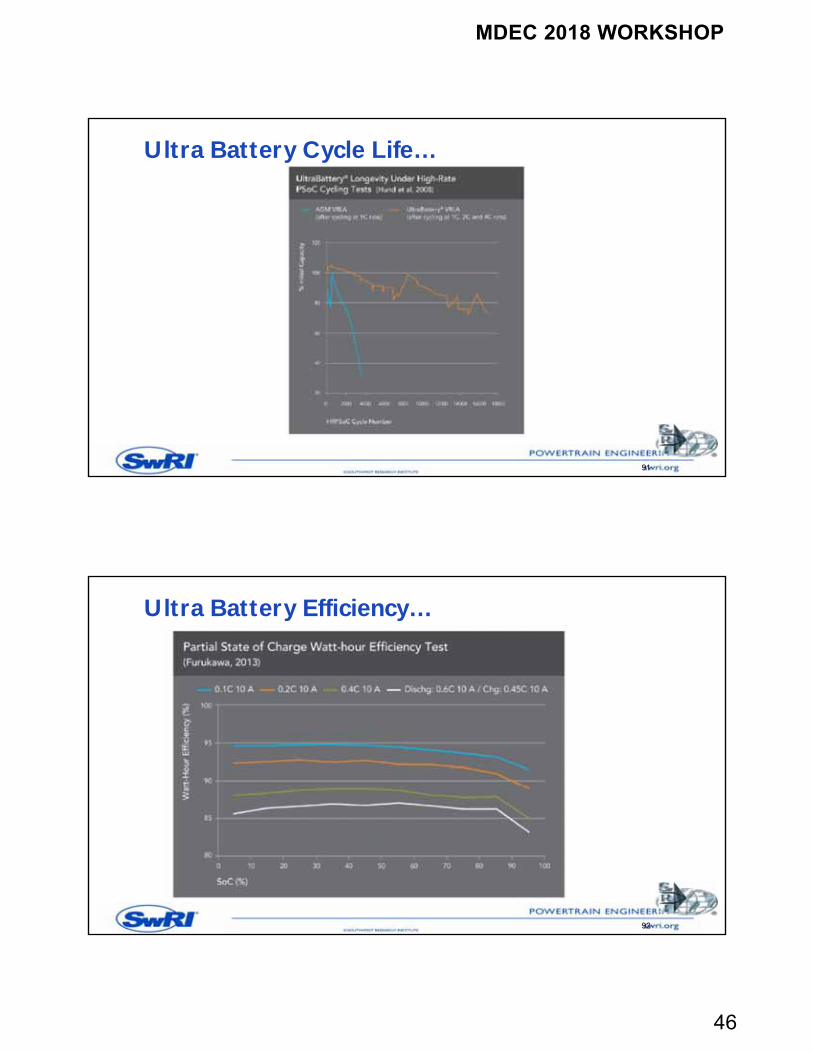
Ultra Battery Cycle Life…
91
Ultra Battery Efficiency…
92

MDEC 2018 WORKSHOP
47
Ultra Battery PV Hybrid Cycling
93
Ultra Battery Charge Acceptance
94
MDEC 2018 WORKSHOP
48
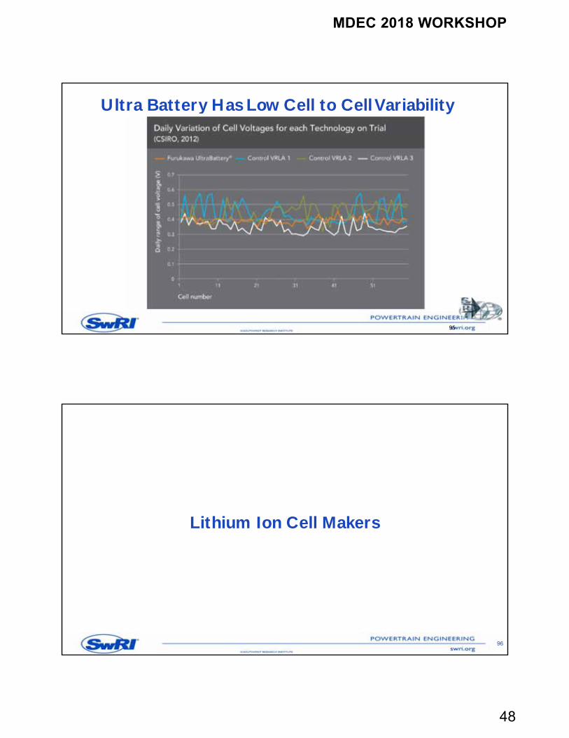
Ultra Battery Has Low Cell to Cell Variability
95
Lithium Ion Cell Makers
96
MDEC 2018 WORKSHOP
49
97
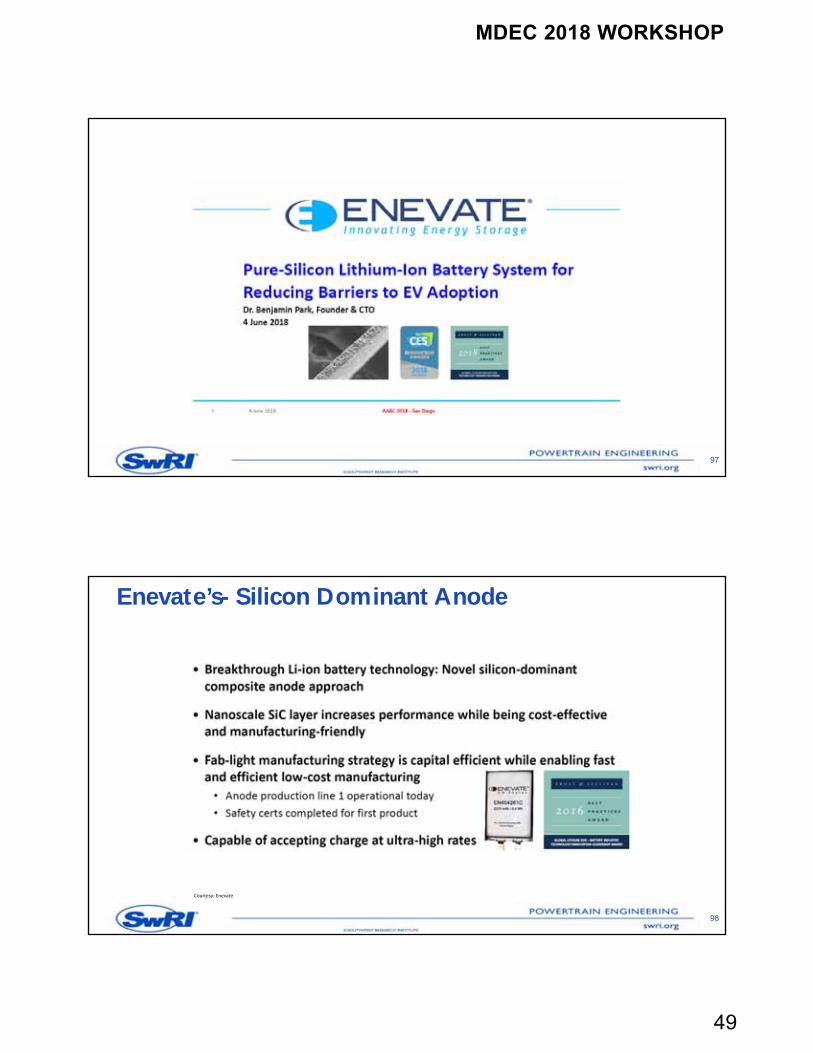
Enevate’s- Silicon Dominant Anode
98
Courtesy: Enevate
MDEC 2018 WORKSHOP
50
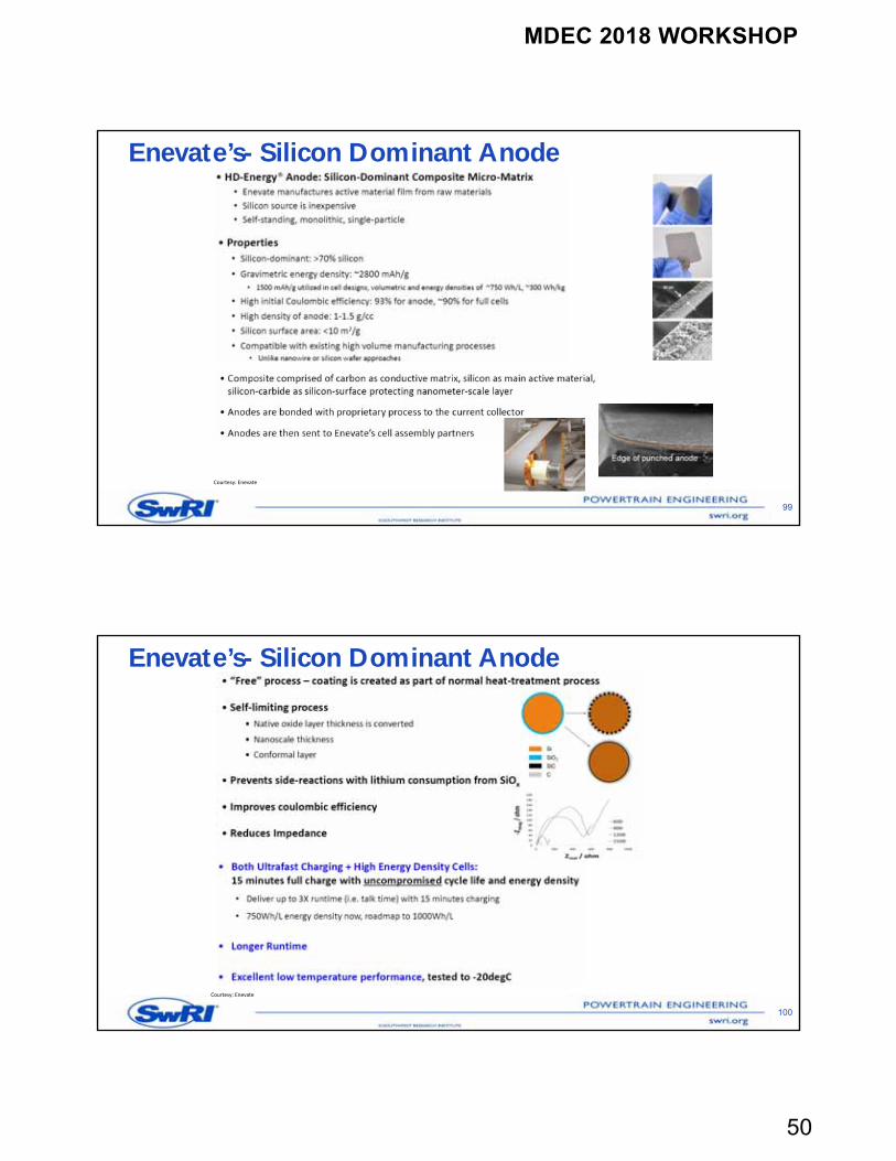
Enevate’s- Silicon Dominant Anode
99
Courtesy: Enevate
Enevate’s- Silicon Dominant Anode
100
Courtesy: Enevate
MDEC 2018 WORKSHOP
51
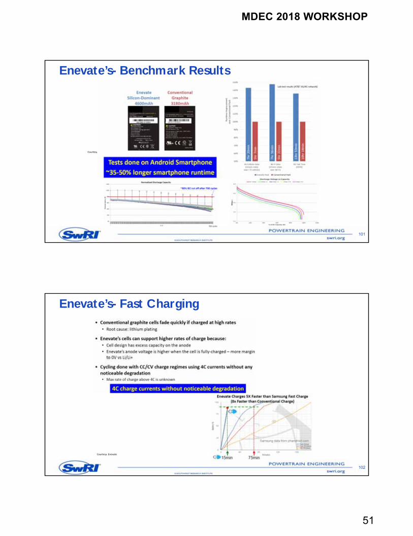
Enevate’s- Benchmark Results
101
Courtesy: Enevate
Enevate’s- Fast Charging
102
Courtesy: Enevate
MDEC 2018 WORKSHOP
52
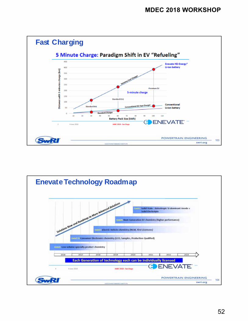
Fast Charging
103
EnevateTechnology Roadmap
104
MDEC 2018 WORKSHOP
53
105
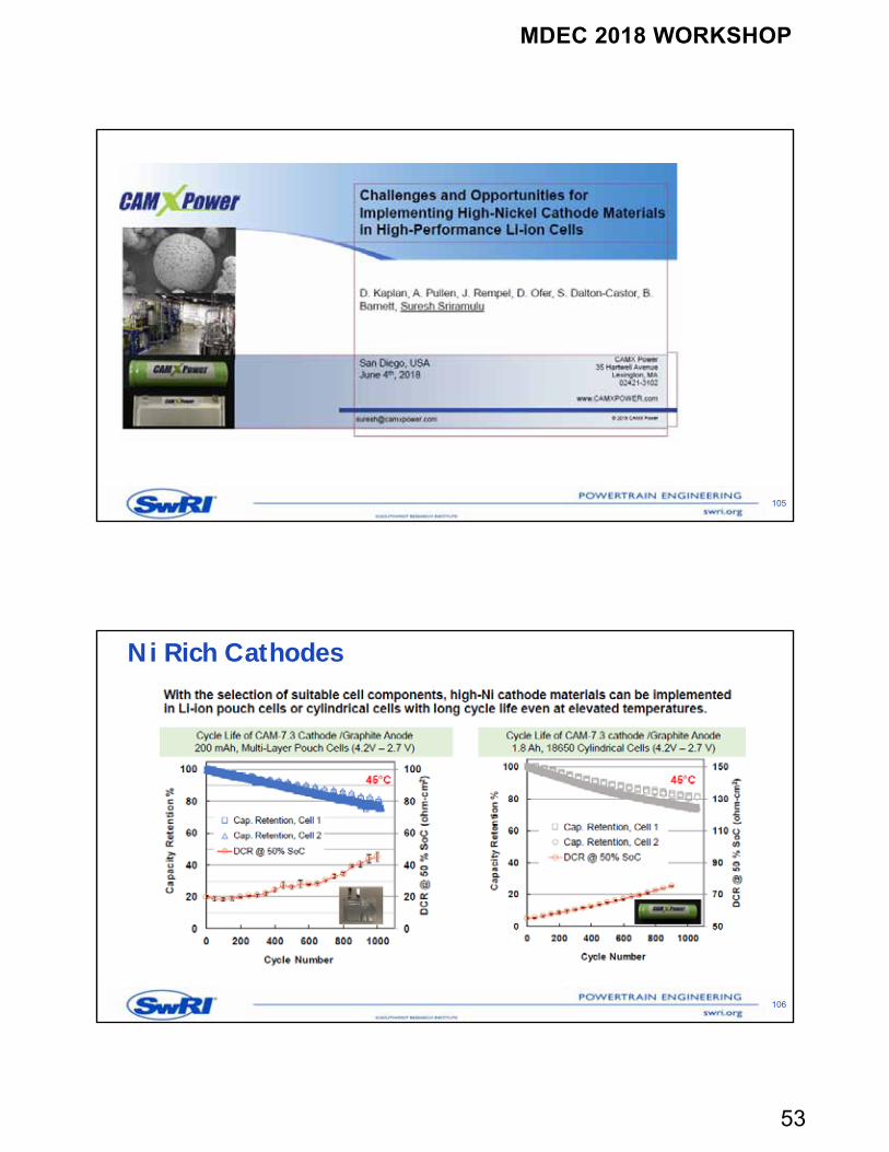
Ni Rich Cathodes
106
MDEC 2018 WORKSHOP
54
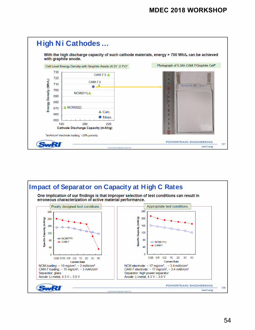
High Ni Cathodes …
107
Impact of Separator on Capacity at High C Rates
108
MDEC 2018 WORKSHOP
55
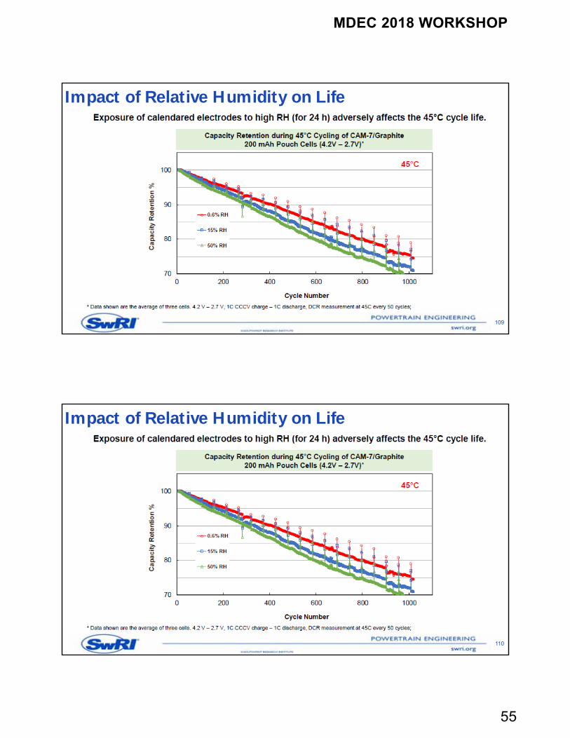
Impact of Relative Humidity on Life
109
Impact of Relative Humidity on Life
110
MDEC 2018 WORKSHOP
56
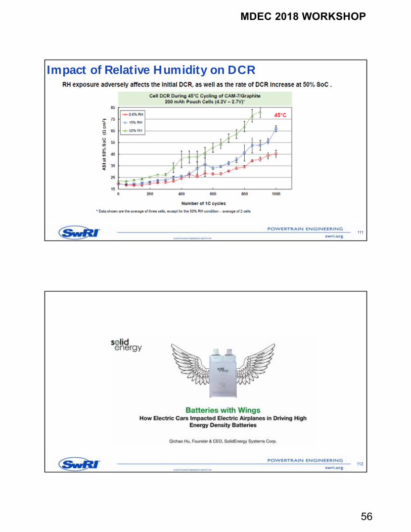
Impact of Relative Humidity on DCR
111
112
MDEC 2018 WORKSHOP
57
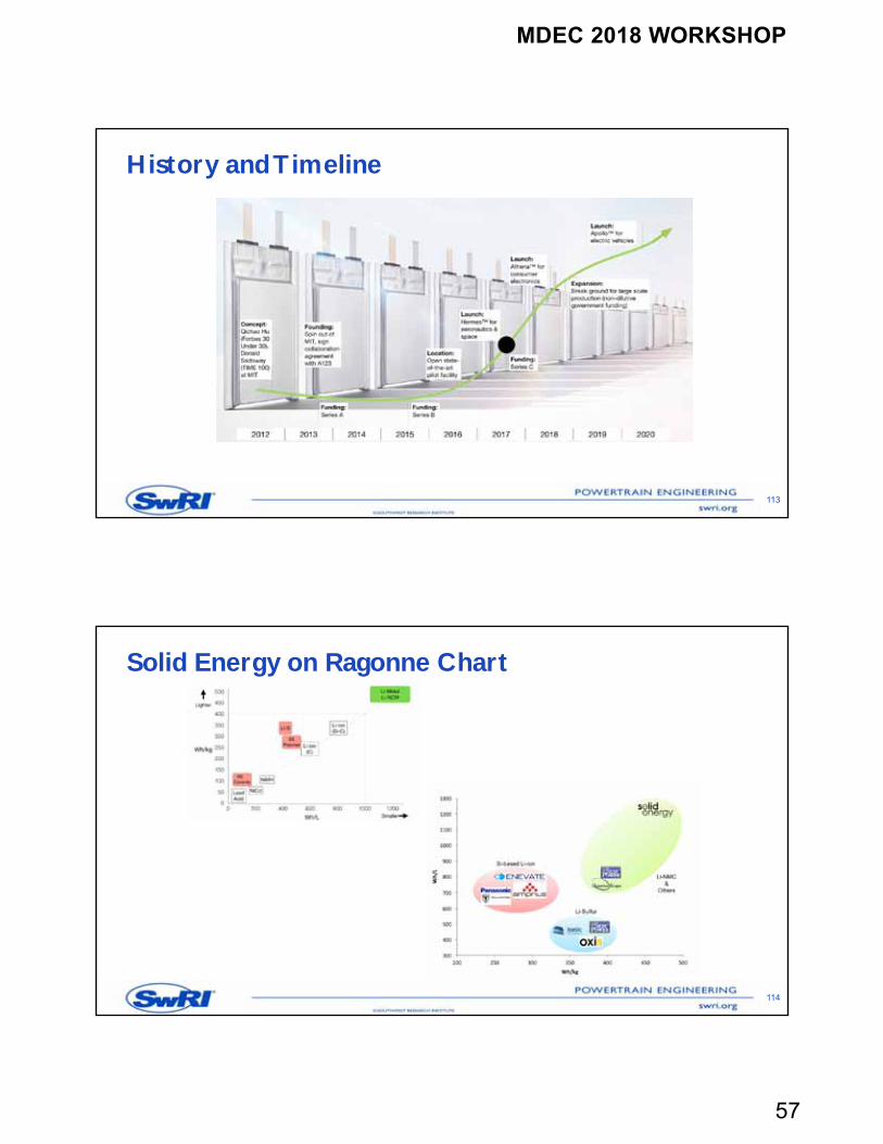
History and Timeline
113
Solid Energy on Ragonne Chart
114
MDEC 2018 WORKSHOP
58
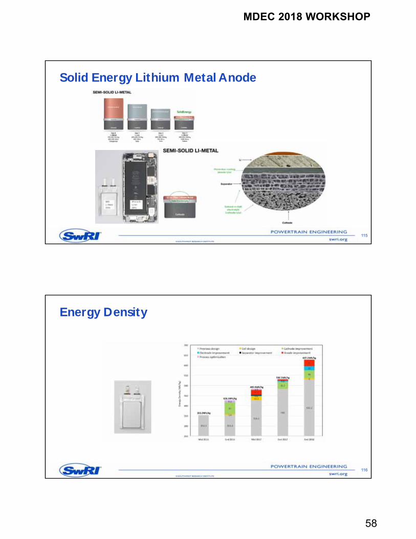
Solid Energy Lithium Metal Anode
115
Energy Density
116
MDEC 2018 WORKSHOP
59
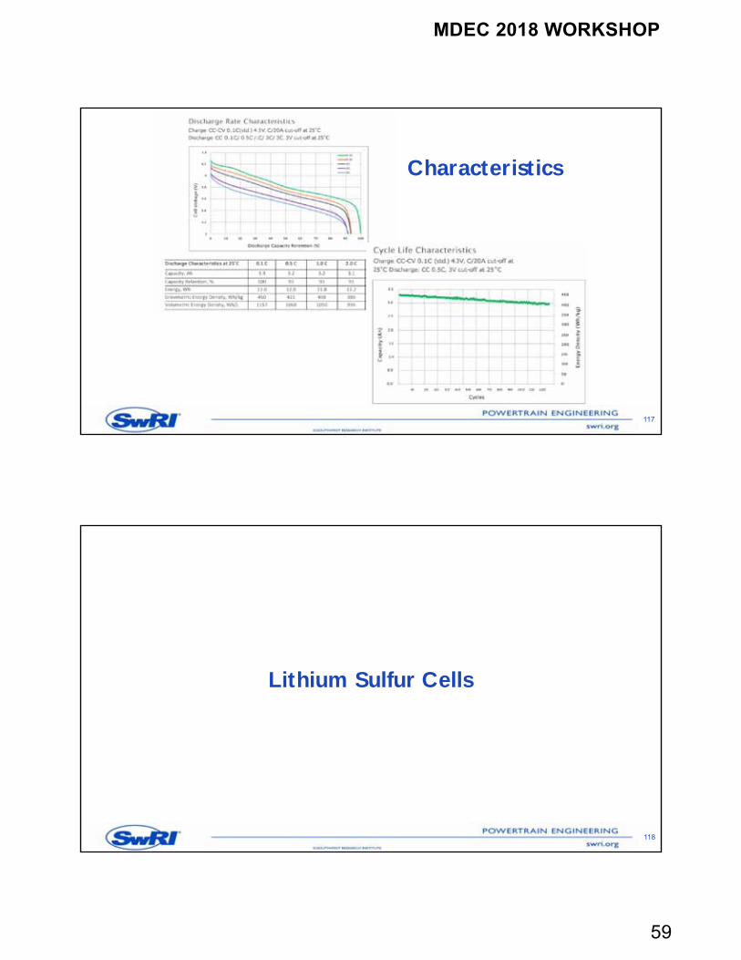
Characteristics
117
Lithium Sulfur Cells
118
MDEC 2018 WORKSHOP
60
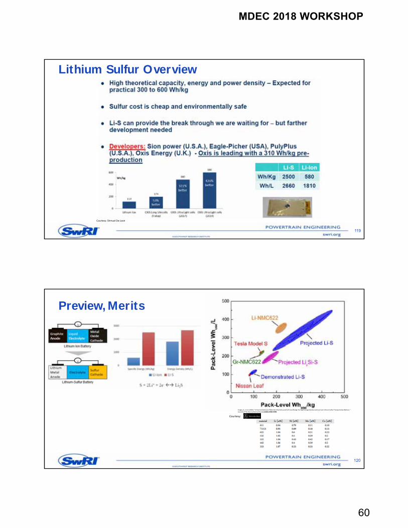
Lithium Sulfur Overview
119
Courtesy: Shmuel De‐Leon
Preview, Merits
120
Courtesy:
Eroglu, D., et al. (2015). "Critical Link between Materials Chemistry and Cell‐Level Design for High Energy Density and Low Cost Lithium‐Sulfur Transportation Battery." Journal of The Electrochemical Society162(6): A982‐A990.
MDEC 2018 WORKSHOP
61
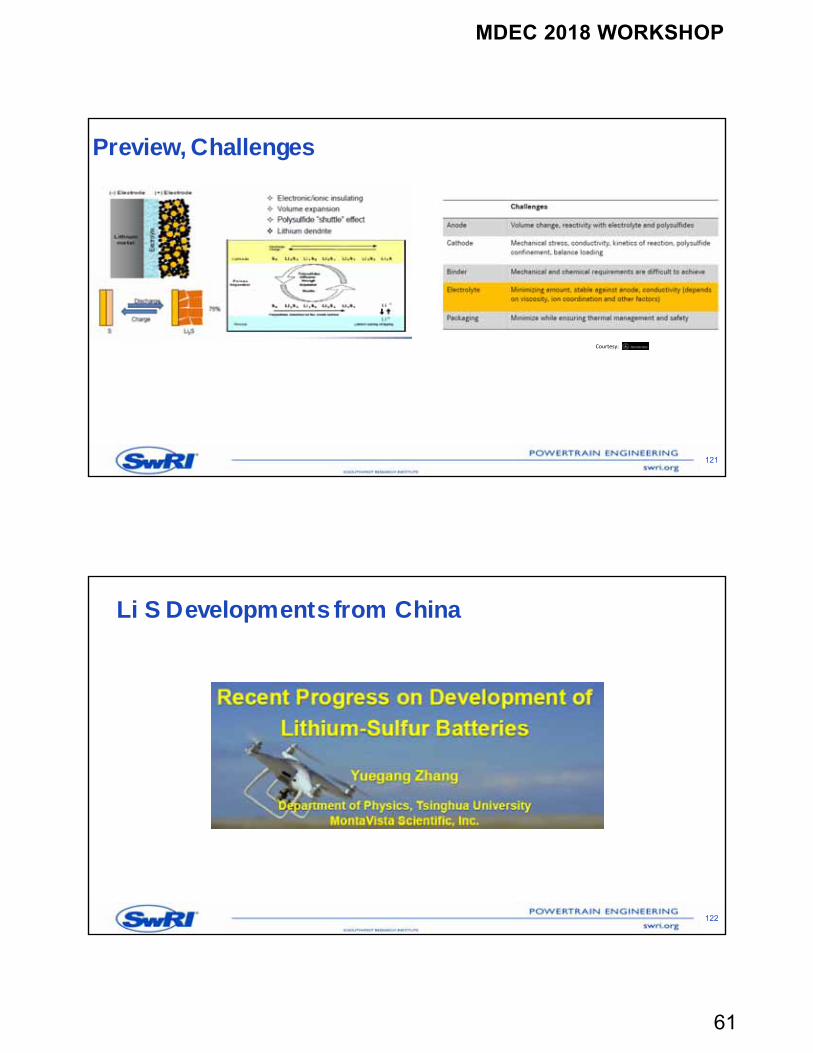
Preview, Challenges
121
Courtesy:
Li S Developments from China
122
MDEC 2018 WORKSHOP
62
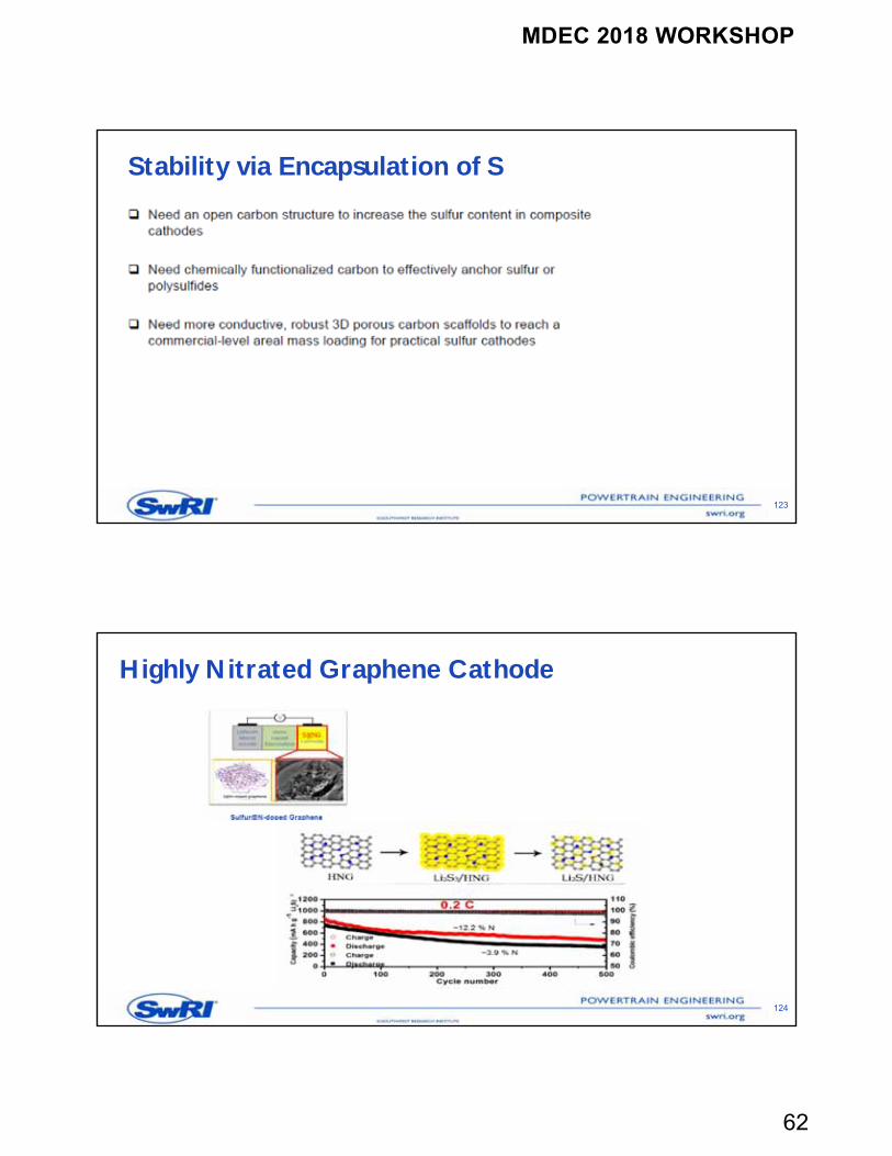
Stability via Encapsulation of S
123
Highly Nitrated Graphene Cathode
124
MDEC 2018 WORKSHOP
63
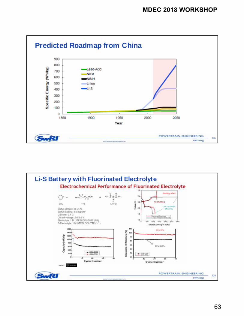
Predicted Roadmap from China
125
Li-S Battery with Fluorinated Electrolyte
126
Courtesy:
MDEC 2018 WORKSHOP
64
Li-S Battery with Fluorinated Electrolyte - Conclusions
127
Courtesy:
Toyota Prius Prime NCM Cells
128
MDEC 2018 WORKSHOP
65
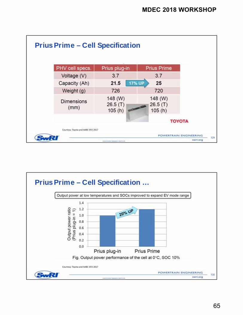
Prius Prime – Cell Specification
129
Courtesy: Toyota and AABC SFO 2017
Prius Prime – Cell Specification …
130
Courtesy: Toyota and AABC SFO 2017
MDEC 2018 WORKSHOP
66
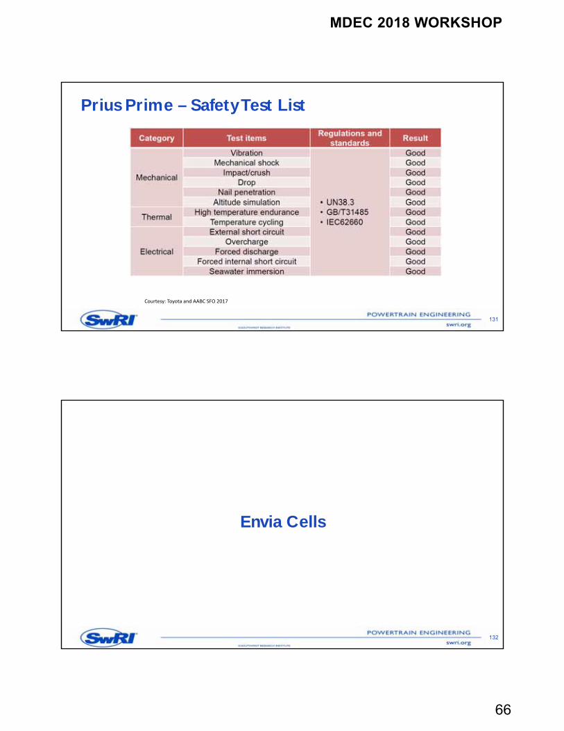
Prius Prime – Safety Test List
131
Courtesy: Toyota and AABC SFO 2017
Envia Cells
132
MDEC 2018 WORKSHOP
67
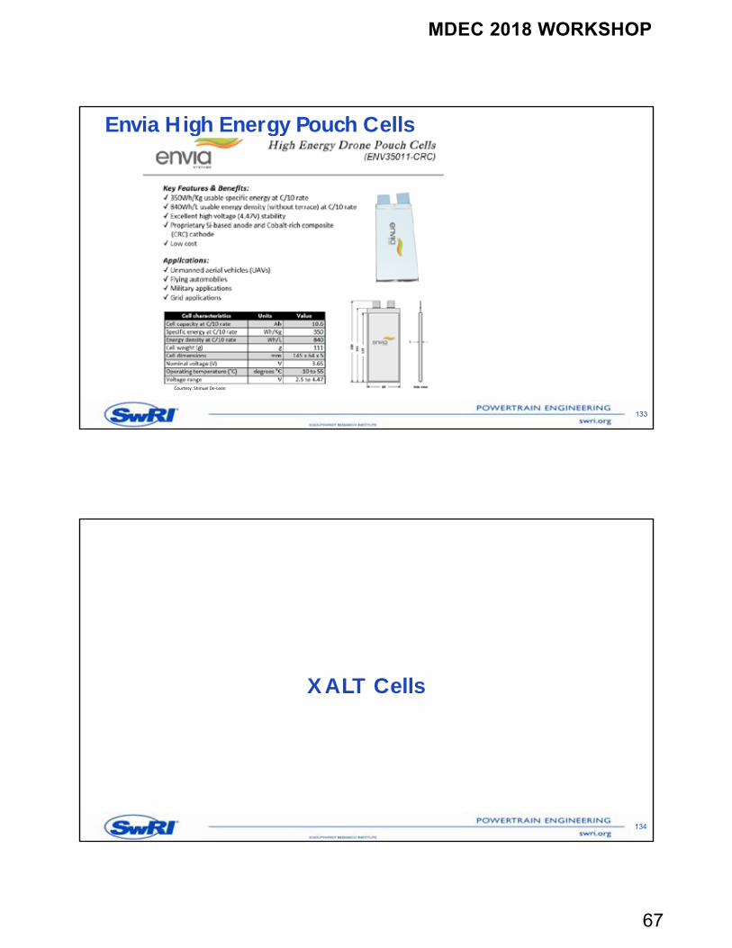
Envia High Energy Pouch Cells
133
Courtesy: Shmuel De‐Leon
XALT Cells
134
MDEC 2018 WORKSHOP
68
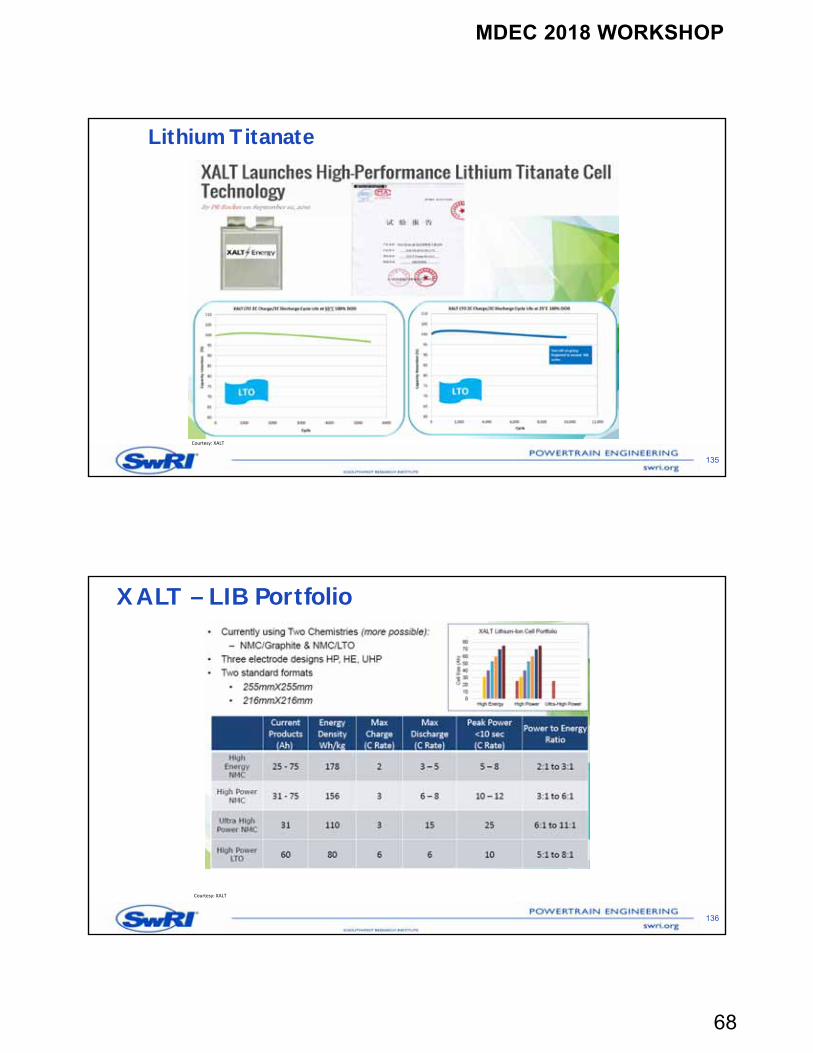
Lithium Titanate
135
Courtesy: XALT
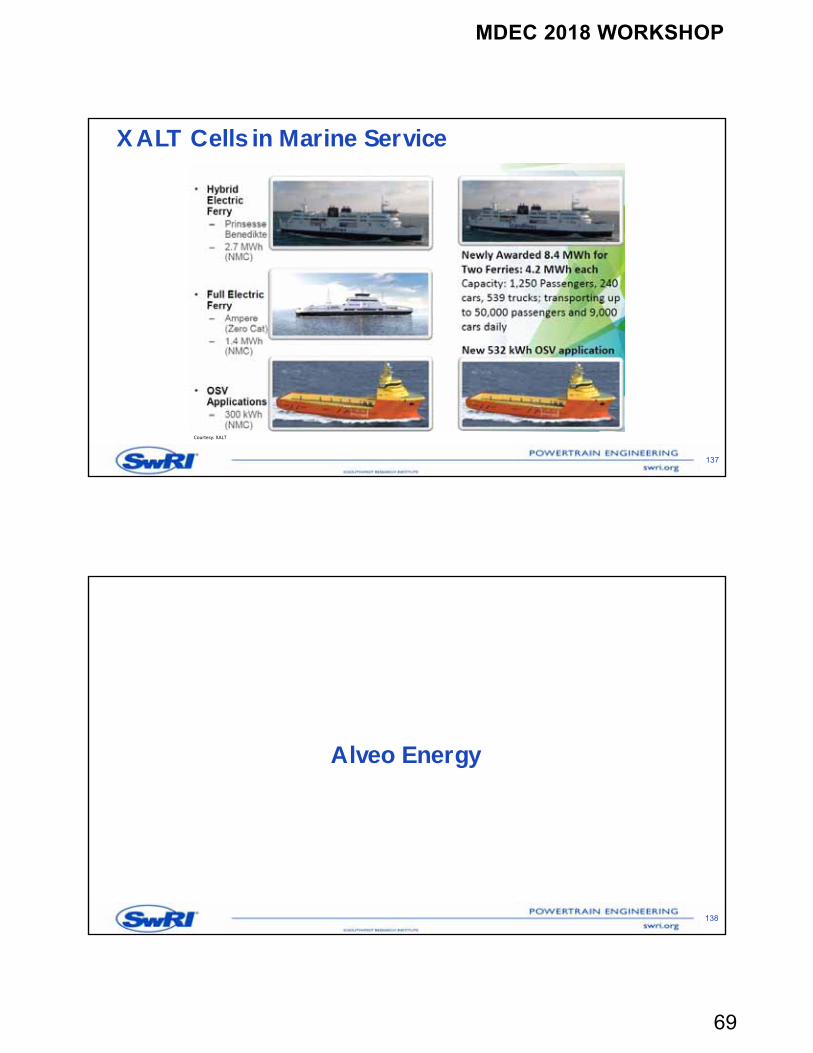
XALT – LIB Portfolio
136
Courtesy: XALT
MDEC 2018 WORKSHOP
69
XALT Cells in Marine Service
137
Courtesy: XALT
Alveo Energy
138
MDEC 2018 WORKSHOP
70
Alveo Energy
139
Alveo Cell Technology
140
MDEC 2018 WORKSHOP
71
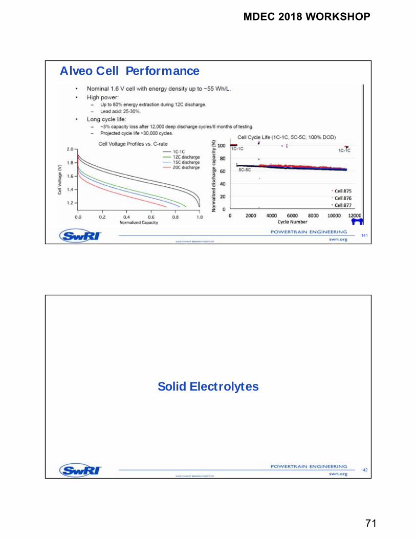
Alveo Cell Performance
141
Solid Electrolytes
142
MDEC 2018 WORKSHOP
72
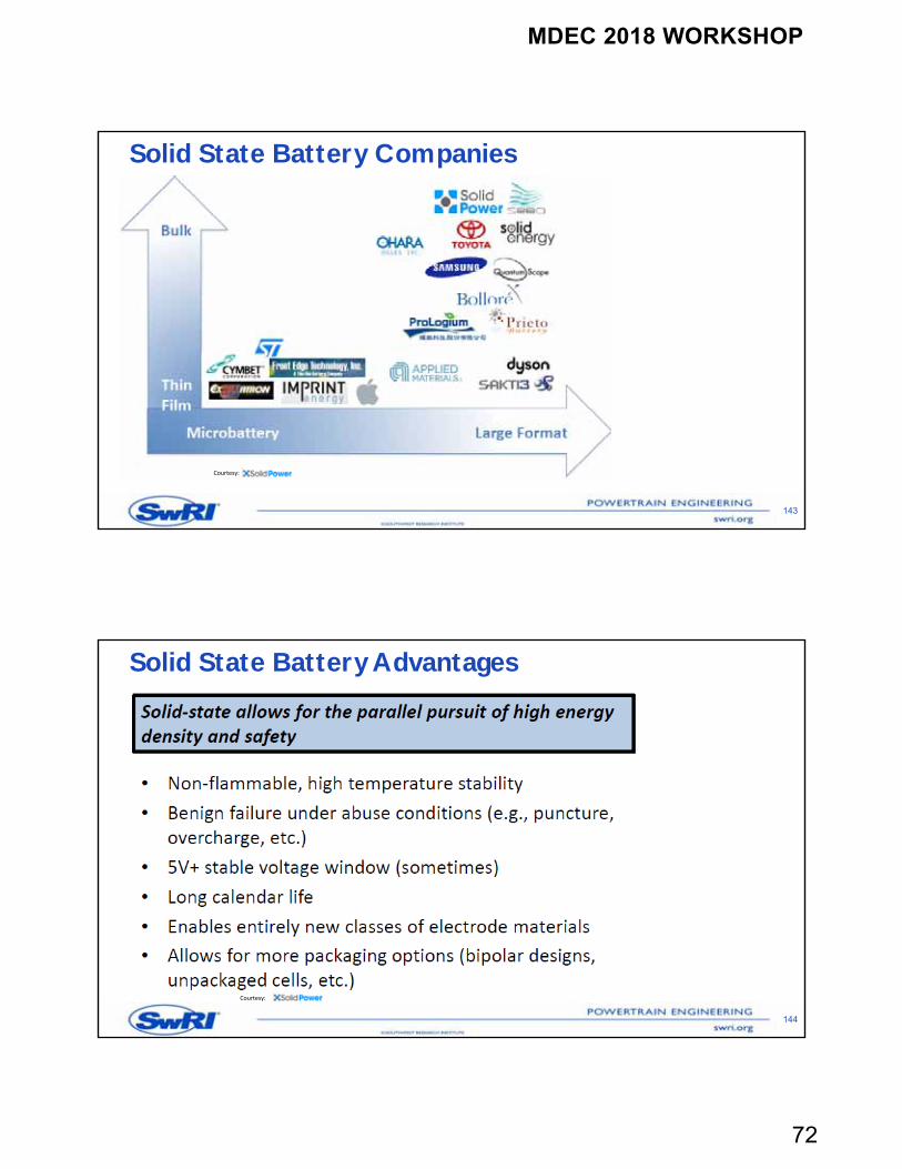
Solid State Battery Companies
143
Courtesy:
Solid State Battery Advantages
144
Courtesy:
MDEC 2018 WORKSHOP
73
Solid State Battery Challenges
145Courtesy:
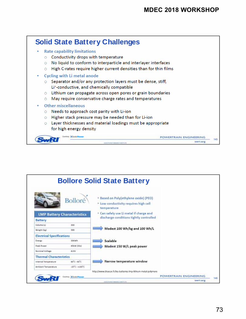
Bollore Solid State Battery
146Courtesy:
MDEC 2018 WORKSHOP
74
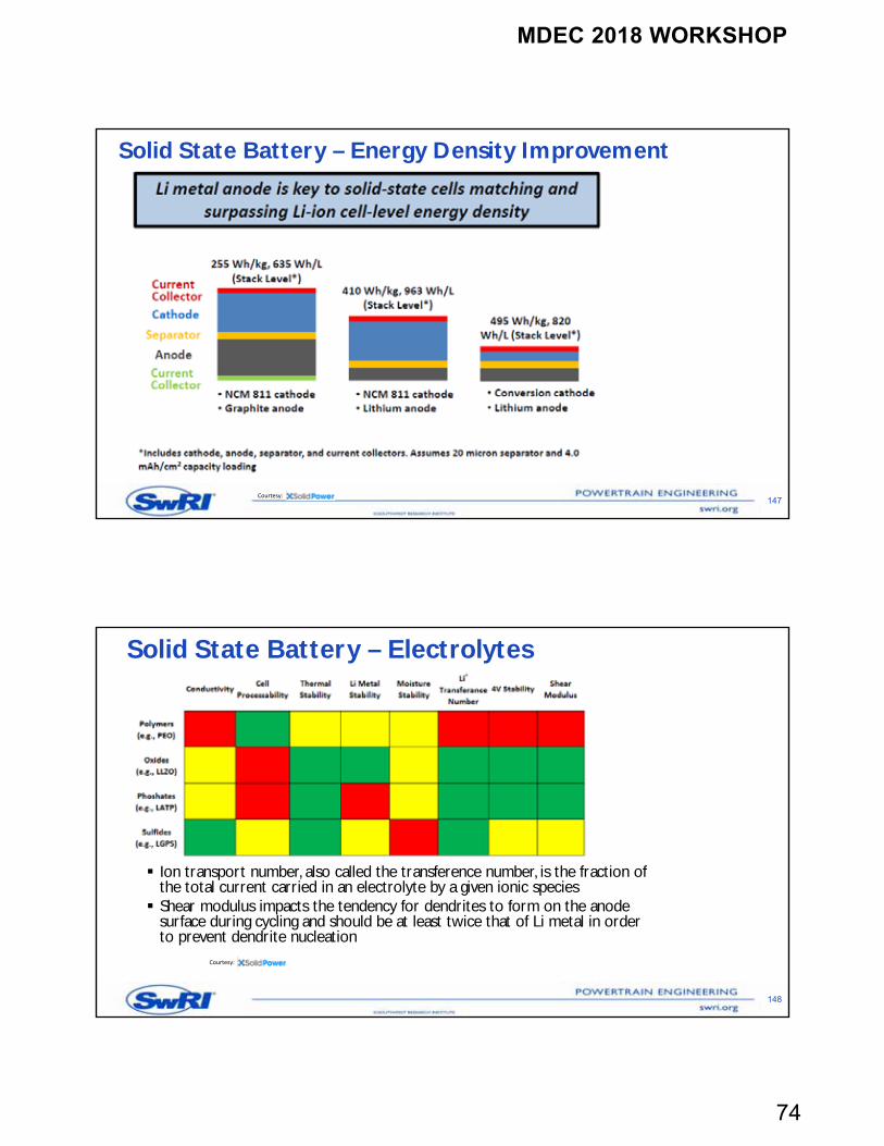
Solid State Battery – Energy Density Improvement
147Courtesy:
Solid State Battery – Electrolytes
Ion transport number, also called the transference number, is the fraction of the total current carried in an electrolyte by a given ionic species Shear modulus impacts the tendency for dendrites to form on the anode
surface during cycling and should be at least twice that of Li metal in order to prevent dendrite nucleation
148
Courtesy:
MDEC 2018 WORKSHOP
75
149
Courtesy:
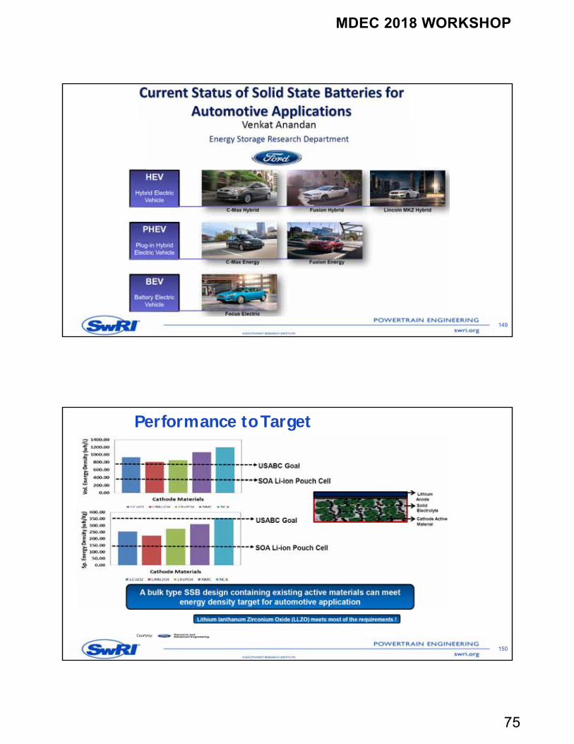
Performance to Target
150
Courtesy:
MDEC 2018 WORKSHOP
76
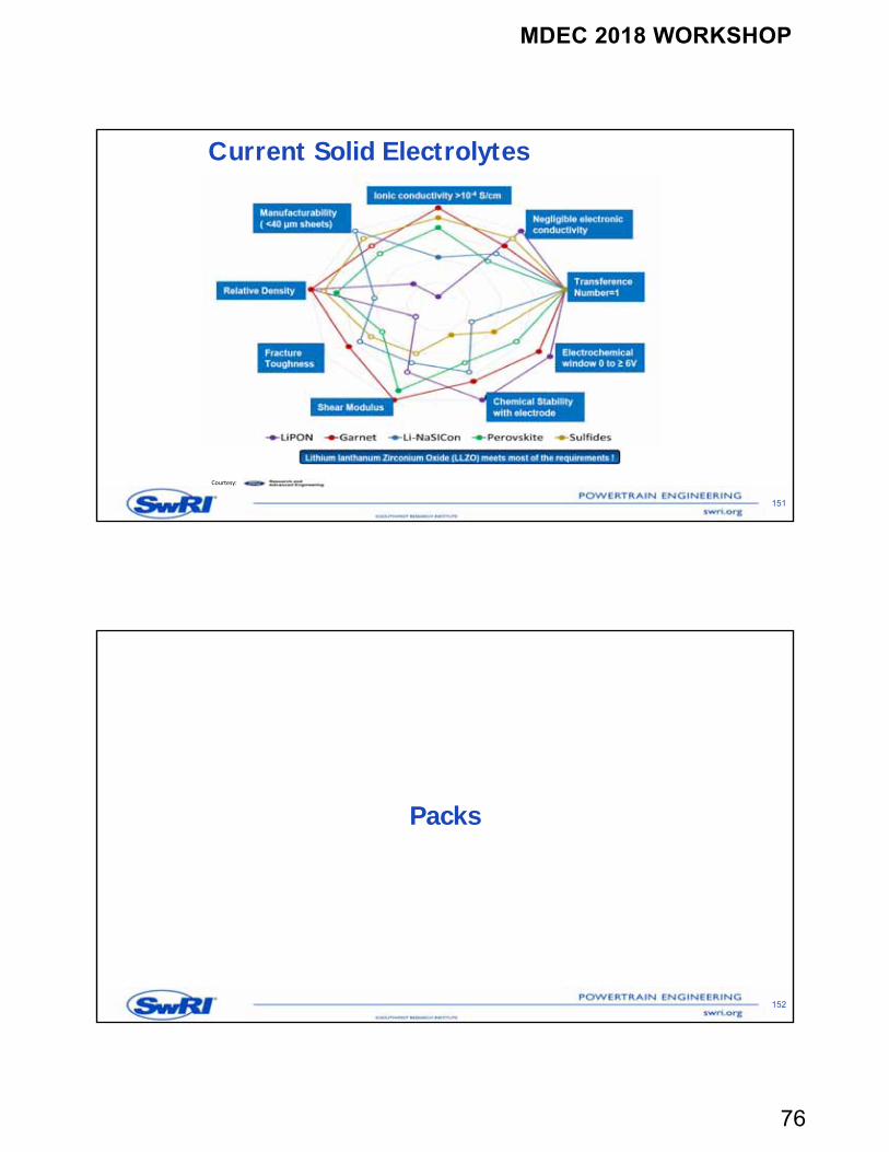
Current Solid Electrolytes
151
Courtesy:
Packs
152
MDEC 2018 WORKSHOP
77
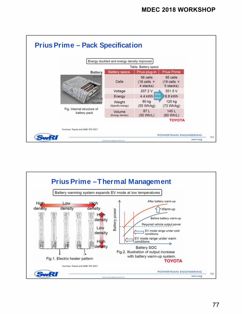
Prius Prime – Pack Specification
153
Courtesy: Toyota and AABC SFO 2017
Prius Prime –Thermal Management
154
Courtesy: Toyota and AABC SFO 2017
MDEC 2018 WORKSHOP
78
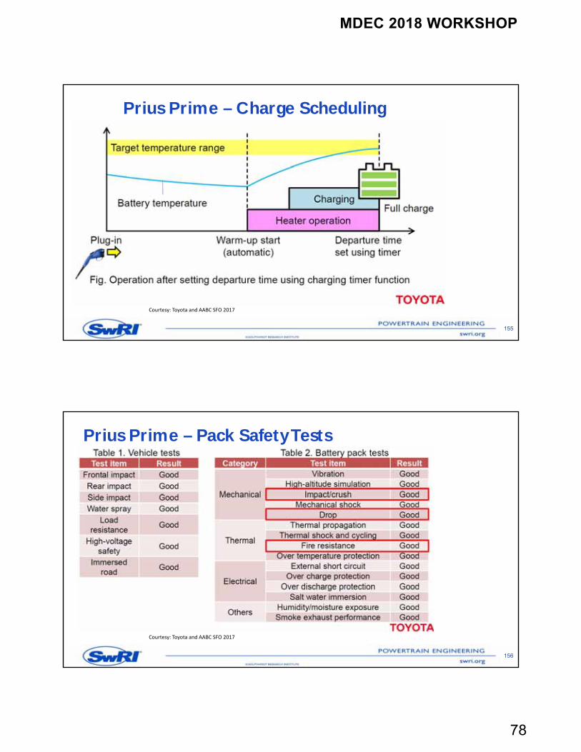
Prius Prime – Charge Scheduling
155
Courtesy: Toyota and AABC SFO 2017
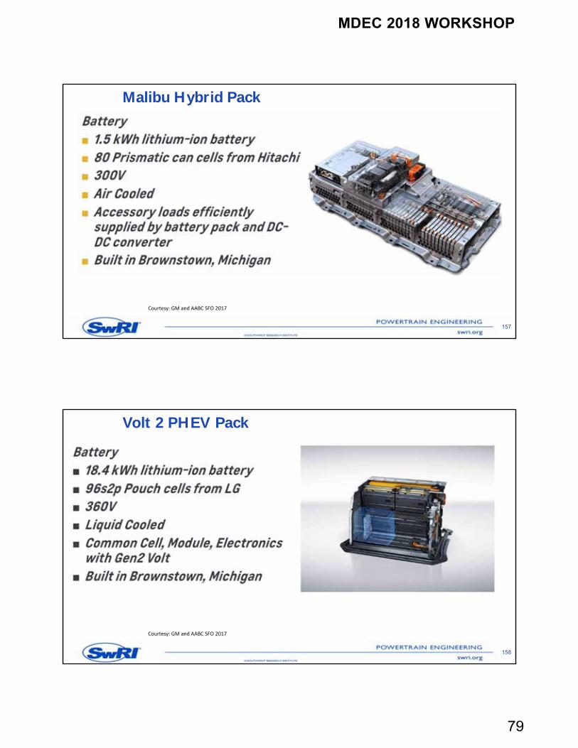
Prius Prime – Pack Safety Tests
156
Courtesy: Toyota and AABC SFO 2017
MDEC 2018 WORKSHOP
79
Malibu Hybrid Pack
157
Courtesy: GM and AABC SFO 2017
Volt 2 PHEV Pack
158
Courtesy: GM and AABC SFO 2017
MDEC 2018 WORKSHOP
80
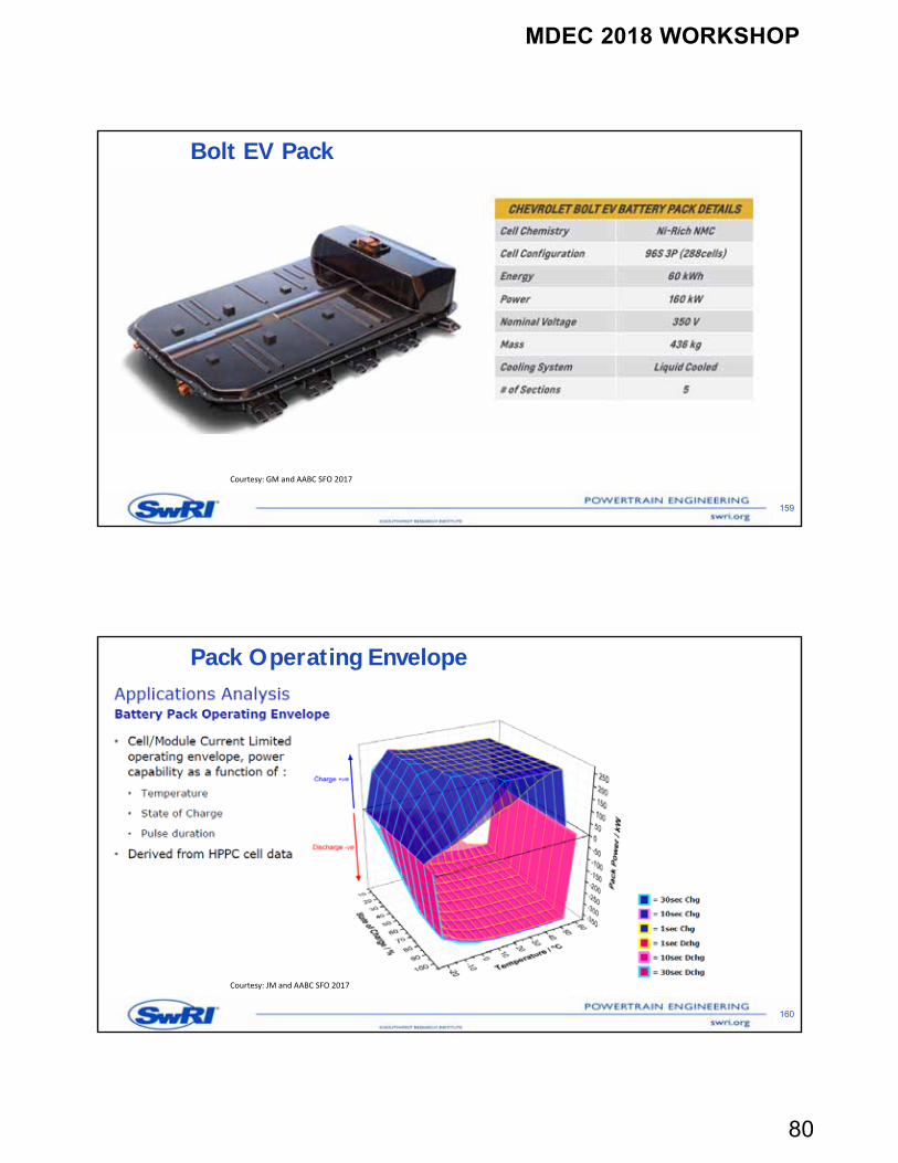
Bolt EV Pack
159
Courtesy: GM and AABC SFO 2017
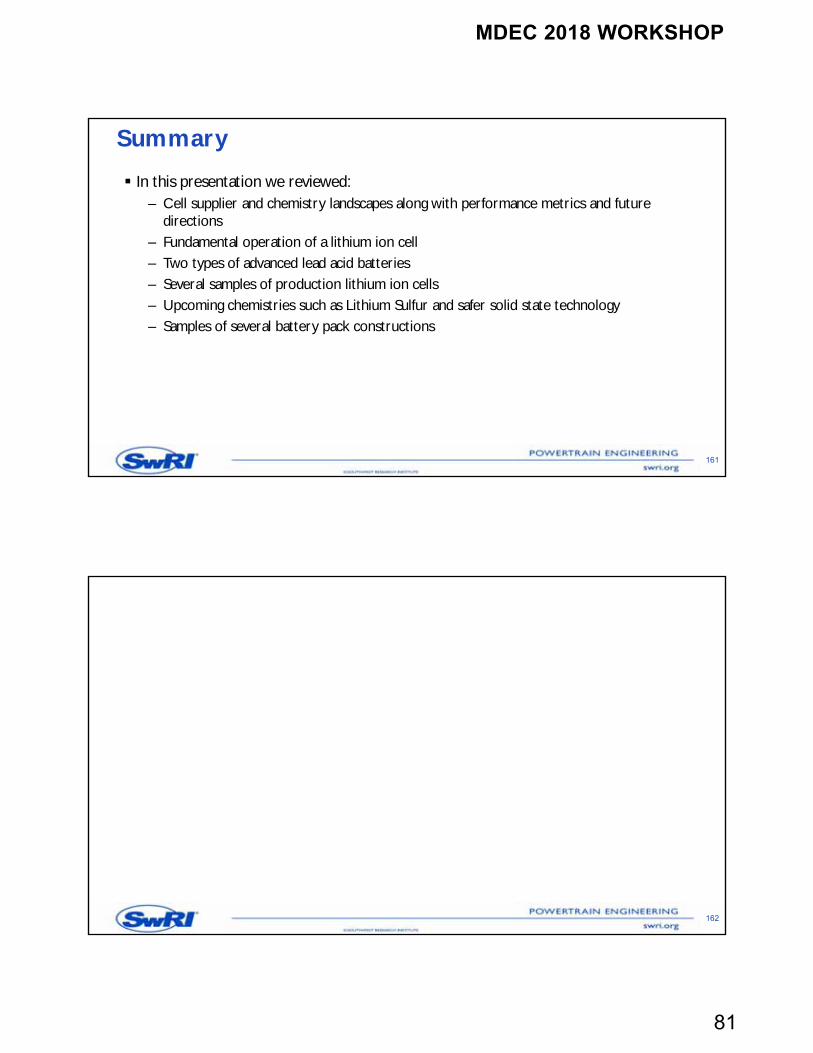
Pack Operating Envelope
160
Courtesy: JM and AABC SFO 2017
MDEC 2018 WORKSHOP
81
Summary
In this presentation we reviewed:– Cell supplier and chemistry landscapes along with performance metrics and future
directions– Fundamental operation of a lithium ion cell– Two types of advanced lead acid batteries– Several samples of production lithium ion cells– Upcoming chemistries such as Lithium Sulfur and safer solid state technology– Samples of several battery pack constructions
161
162
MDEC 2018 WORKSHOP
82
Benchmarking of Lithium Ion Cells
Bapi Surampudi, Ph.D.
164
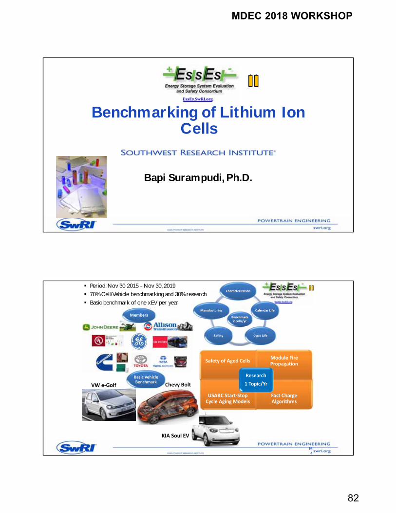
Period: Nov 30 2015 - Nov 30, 2019 70% Cell/Vehicle benchmarking and 30% research Basic benchmark of one xEV per year
Benchmark 2 cells/yr
Characterization
Calendar Life
Cycle LifeSafety
Manufacturing
Safety of Aged CellsModule Fire Propagation
USABC Start‐Stop Cycle Aging Models
Fast Charge Algorithms
Research
1 Topic/YrVW e‐Golf Chevy Bolt
Members
Basic Vehicle Benchmark
KIA Soul EV
MDEC 2018 WORKSHOP
83
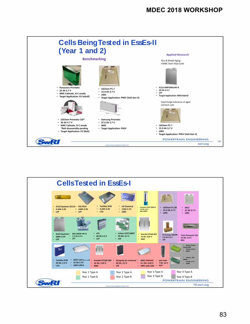
Cells Being Tested in EssEs-II (Year 1 and 2)
165
• LGChem P1.7• 15.9 Ah 3.7 V• LMO• Target Application: PHEV (Volt Gen II)
• Panasonic Prismatic• 25 Ah 3.7 V• NMC Cathode, Si‐C anode • Target Application: EV (eGolf)
• A123 AMP20M1HD‐A• 20 Ah 3.3 V• LFP• Target Application: Mild Hybrid
• LGChem P1.7• 15.9 Ah 3.7 V• LMO• Target Application: PHEV (Volt Gen II)
• LGChem Prismatic Cell*• 56 Ah 3.7 V • NMC Cathode, Si‐C anode
*Bolt disassembly pending • Target Application: EV (Bolt)
• Samsung Prismatic• 37.6 Ah 3.7 V• NMC• Target Application: PHEV
Test & Model Aging ‐USABC Start‐Stop Cycle
Overcharge tolerance of aged LGChem cells
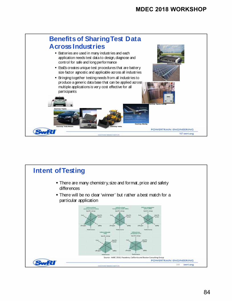
Cells Tested in EssEs-I
166
• A123 Systems 32113• 4.4Ah 3.3V• LFP
• EIG F014• 14Ah 3.3V• LFP
• Toshiba SCiB• 4.2Ah 2.4V• LTO
• LG Chemical• 15Ah 3.7V• LMO
• A123 Systems• 20Ah 3.3V• LFP
• BAK 26650 HP‐Fe• 2.2 Ah 3.2 V• LFP
• ATL• 60 Ah 3.2 V• LFP
• Lishen LP2714897 • 20 Ahr 3.2 V• LFP
• Enerdel CP160‐365• 16 Ah, 3.65 V• NMC
• AESC Cell (Nissan Leaf)• 33 Ah 3.7V• LMO+LNCA
• Toshiba SCiB• 20 Ah, 2.3 V• LTO
• Sinopoly (SP‐LFP40AHA)• 40 Ah, 3.2 V• LFP
• AESC (Infiniti)• 4.1 Ah, 4.65 V• LMO with LNO
• Saft VL6H• 7 Ah, 3.6 V• NCA
• Panasonic NCR 18650 A• 3.0 Ah, 3.6 V• NCA (NNP)
Year 1 Type A
Year 1 Type B
Year 2 Type A
Year 2 Type B
Year 3 Type A
• Enerdel CP160‐365• 16 Ah, 3.65 V• NMC
• LGChem P1.5B• 15.9 Ah 3.7 V• LMO
Year 3 Type B
Year 4 Type A
• XALT• 31 Ah 3.7 V• LMO
• Tesla Panasonic Cell• 3.0 Ah, 3.6 V• NCA
• K2 Energy 26650P• 2.6 Ah 3.2 V• LFP
• Boston Power Swing 5300• 5.3 Ah, 3.65 V• LMO?
• Valence IFR 26650
2.4 Ah, 3.2 V• LFMP
Year 4 Type B
MDEC 2018 WORKSHOP
84
167
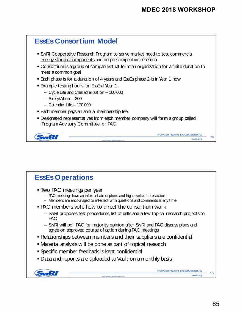
Batteries are used in many industries and each application needs test data to design, diagnose and control for safe and long performance
EssEs creates unique test procedures that are battery size factor agnostic and applicable across all industries
Bringing together testing needs from all industries to produce a generic data base that can be applied across multiple applications is very cost effective for all participants
Benefits of Sharing Test Data Across Industries
Courtesy: Aquion EnergyCourtesy: Aquion Energy
Courtesy: SamsungCourtesy: Samsung
Courtesy: BeoingCourtesy: Beoing
Courtesy: VolvoCourtesy: VolvoCourtesy: Tesla MotorsCourtesy: Tesla Motors
Courtesy: ToyotaCourtesy: Toyota
Courtesy: DellCourtesy: Dell
Intent of Testing
There are many chemistry, size and format, price and safety differences There will be no clear ‘winner’ but rather a best match for a
particular application
Source : AABC 2010, Pasadena, California and Boston Consulting Group
168
MDEC 2018 WORKSHOP
85
EssEs Consortium Model
SwRI Cooperative Research Program to serve market need to test commercial energy storage components and do precompetitive research Consortium is a group of companies that form an organization for a finite duration to
meet a common goal Each phase is for a duration of 4 years and EssEs phase 2 is in Year 1 now Example testing hours for EssEs-I Year 1
– Cycle Life and Characterization – 160,000– Safety/Abuse - 300– Calendar Life – 170,000
Each member pays an annual membership fee Designated representatives from each member company will form a group called
‘Program Advisory Committee’ or PAC
169
EssEs Operations
Two PAC meetings per year– PAC meetings have an informal atmosphere and high levels of interaction– Members are encouraged to interject with questions and comments at any time
PAC members vote how to direct the consortium work– SwRI proposes test procedures, list of cells and a few topical research projects to
PAC– SwRI will poll PAC for majority opinion after SwRI and PAC discuss plans and
agree on approved course of action during PAC meetings
Relationships between members and their suppliers are confidentialMaterial analysis will be done as part of topical research Specific member feedback is kept confidentialData and reports are uploaded to Vault on a monthly basis
170
MDEC 2018 WORKSHOP
86
How to Join EssEs-II ?
SwRI will provide the standard consortium contract to you for approvals Membership cost for EssEs II is
– $65,000 a year for EssEs-I members– $75,000 a year for new members– $32,000 a year for small companies with restricted data access and voting rights
SwRI will invoice every year in March
171
List of Deliverables
Complete data set in binary (mat) and ascii (text) format– SwRI executes PAC plan and presents test data at PAC meetings– Test Procedures and Raw data are posted on EssEs Web Site for secure member access
(https://vault.swri.org/esses)
Basic and comparative data analysis Monthly progress reports Two PAC meetings every year Status on SwRI internal research during PAC meetings Results of one topical research per year Industry update from conferences Guest presentations
172
MDEC 2018 WORKSHOP
87
EssEs Work Scope
173
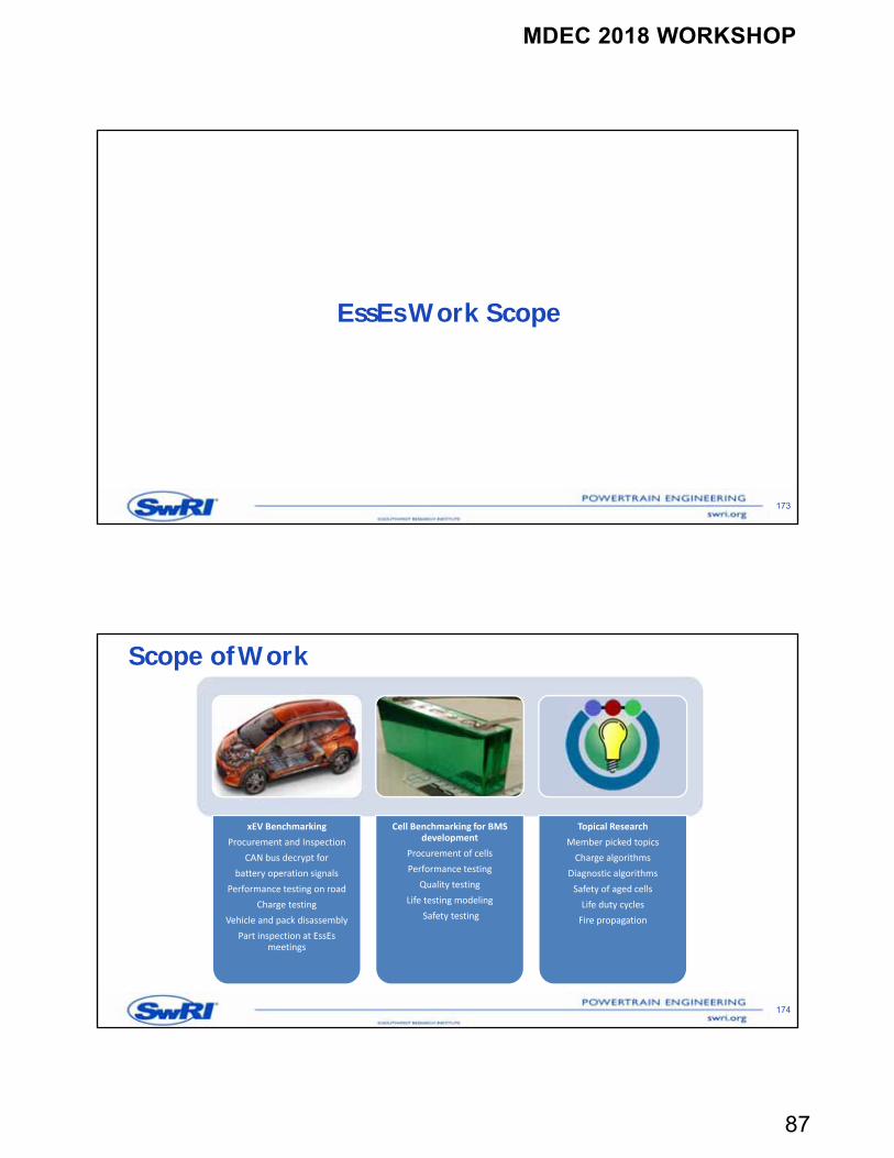
Scope of Work
174
xEV Benchmarking
Procurement and Inspection
CAN bus decrypt for
battery operation signals
Performance testing on road
Charge testing
Vehicle and pack disassembly
Part inspection at EssEs meetings
Cell Benchmarking for BMS development
Procurement of cells
Performance testing
Quality testing
Life testing modeling
Safety testing
Topical Research
Member picked topics
Charge algorithms
Diagnostic algorithms
Safety of aged cells
Life duty cycles
Fire propagation
MDEC 2018 WORKSHOP
88
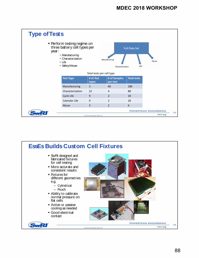
Type of Tests
Perform testing regime on three battery cell types per year:
• Manufacturing• Characterization• Life • Safety/Abuse
175
Test Type # of Testtypes
# of Samples per test
Total tests
Manufacturing 3 60 180
Characterization 22 4 88
Cycle Life 9 2 18
Calendar Life 9 2 18
Abuse 3 2 6
Total tests per cell type
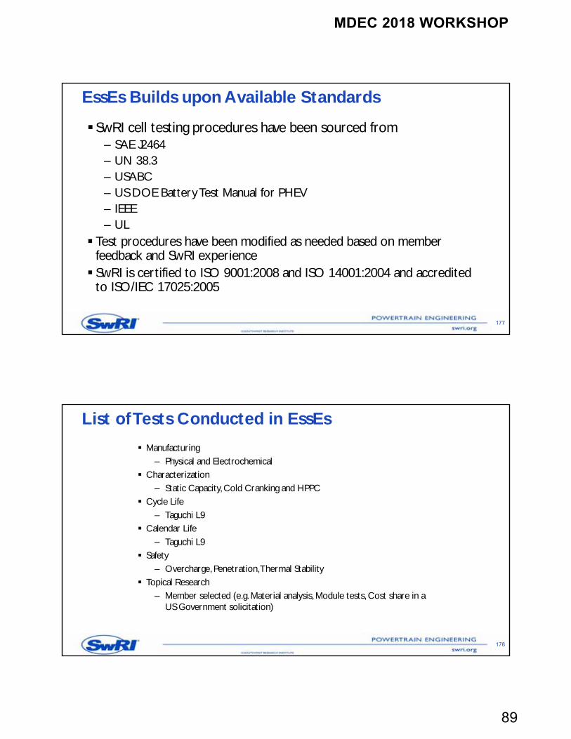
EssEs Builds Custom Cell Fixtures
SwRI designed and fabricated fixtures for cell testing More accurate and
consistent results Fixtures for
different geometries e.g.
– Cylindrical– Pouch
Ability to calibrate normal pressure on flat cells Active or passive
cooling as needed Good electrical
contact
176
MDEC 2018 WORKSHOP
89
EssEs Builds upon Available Standards
SwRI cell testing procedures have been sourced from– SAE J2464– UN 38.3– USABC– US DOE Battery Test Manual for PHEV– IEEE– UL
Test procedures have been modified as needed based on member feedback and SwRI experience SwRI is certified to ISO 9001:2008 and ISO 14001:2004 and accredited
to ISO/IEC 17025:2005
177
List of Tests Conducted in EssEs
Manufacturing – Physical and Electrochemical
Characterization– Static Capacity, Cold Cranking and HPPC
Cycle Life– Taguchi L9
Calendar Life– Taguchi L9
Safety– Overcharge, Penetration, Thermal Stability
Topical Research– Member selected (e.g. Material analysis, Module tests, Cost share in a
US Government solicitation)
178
MDEC 2018 WORKSHOP
90
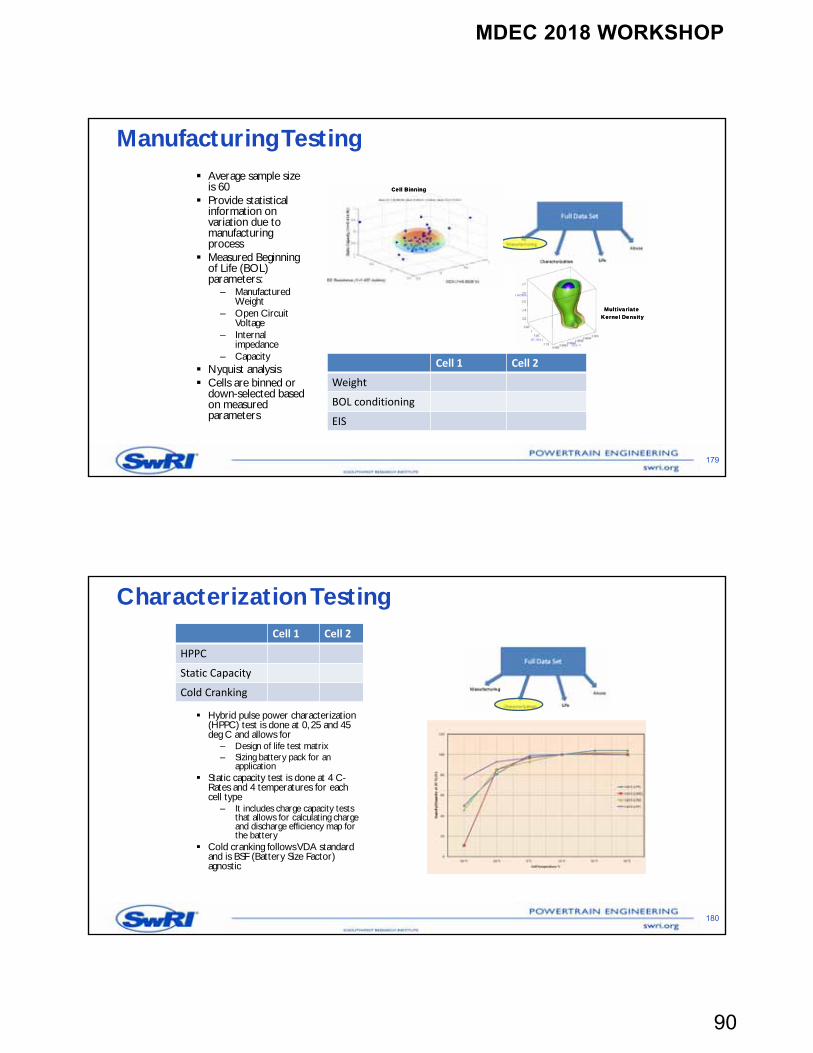
Manufacturing Testing Average sample size
is 60 Provide statistical
information on variation due to manufacturing process
Measured Beginning of Life (BOL) parameters:
– Manufactured Weight
– Open Circuit Voltage
– Internal impedance
– Capacity Nyquist analysis Cells are binned or
down-selected based on measured parameters
179
Cell BinningCell Binning
Multivariate Kernel DensityMultivariate
Kernel Density
Cell 1 Cell 2
Weight
BOL conditioning
EIS
Characterization Testing
Hybrid pulse power characterization (HPPC) test is done at 0, 25 and 45 deg C and allows for
– Design of life test matrix– Sizing battery pack for an
application Static capacity test is done at 4 C-
Rates and 4 temperatures for each cell type
– It includes charge capacity tests that allows for calculating charge and discharge efficiency map for the battery
Cold cranking follows VDA standard and is BSF (Battery Size Factor) agnostic
180
Cell 1 Cell 2
HPPC
Static Capacity
Cold Cranking
MDEC 2018 WORKSHOP
91
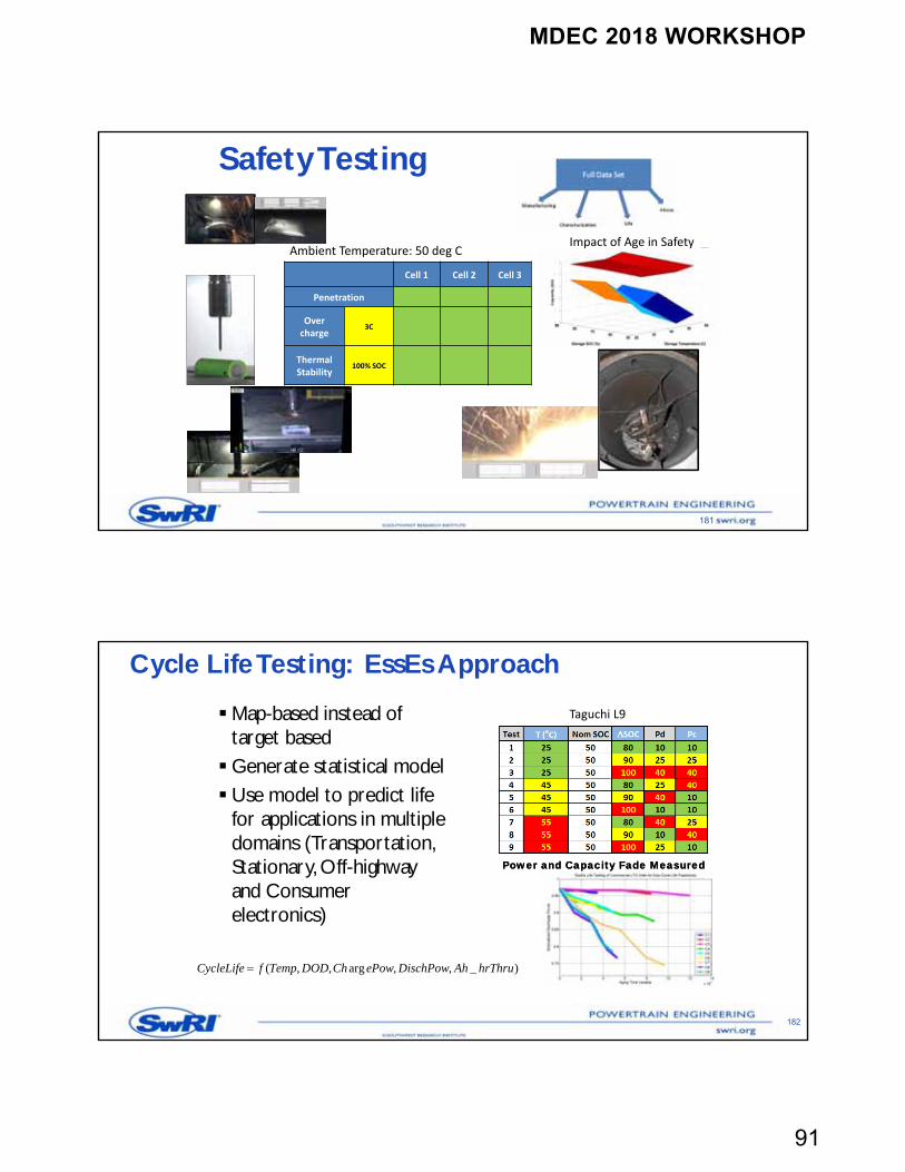
Safety Testing
181
Cell 1 Cell 2 Cell 3
Penetration
Overcharge
3C
ThermalStability
100% SOC
Ambient Temperature: 50 deg CImpact of Age in Safety
Cycle Life Testing: EssEs Approach
Map-based instead of target basedGenerate statistical modelUse model to predict life
for applications in multiple domains (Transportation, Stationary, Off-highway and Consumer electronics)
182
)_,,arg,,( hrThruAhDischPowePowChDODTempfCycleLife
Power and Capacity Fade MeasuredPower and Capacity Fade Measured
Taguchi L9
MDEC 2018 WORKSHOP
92
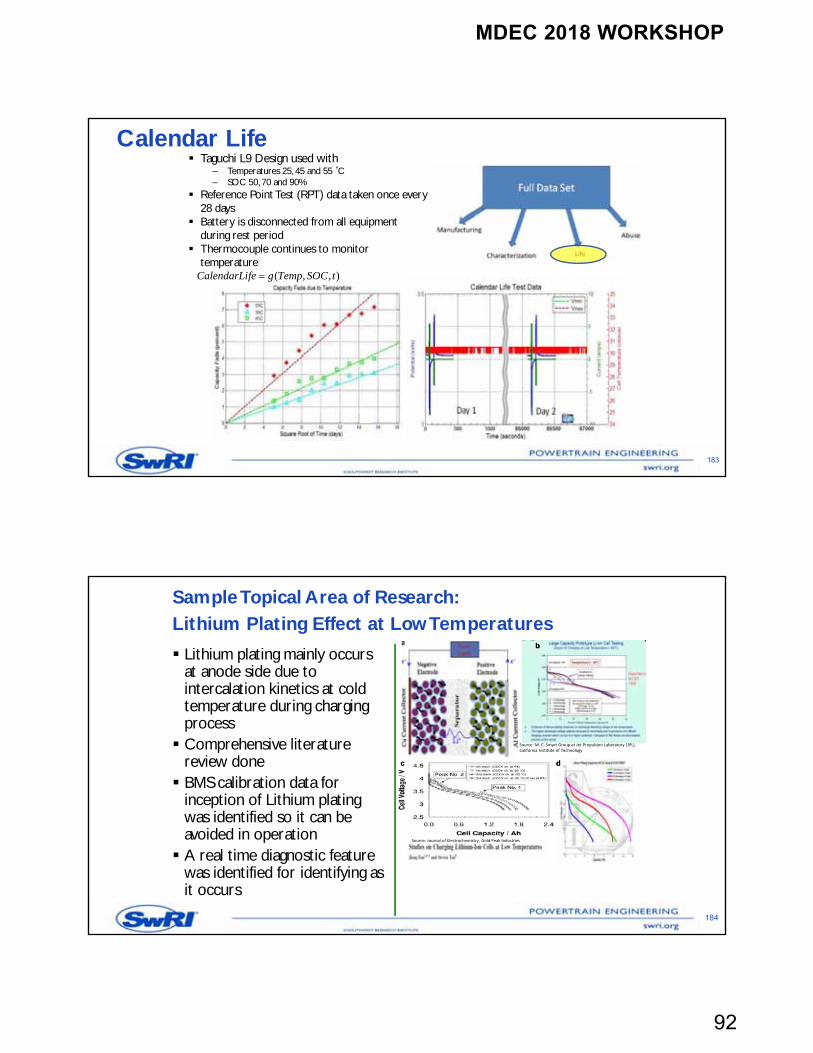
Calendar Life Taguchi L9 Design used with
– Temperatures 25, 45 and 55 ˚C– SOC 50, 70 and 90%
Reference Point Test (RPT) data taken once every 28 days
Battery is disconnected from all equipment during rest period
Thermocouple continues to monitor temperature
183
),,( tSOCTempgfeCalendarLi
Sample Topical Area of Research:Lithium Plating Effect at Low Temperatures
184
Lithium plating mainly occurs at anode side due to intercalation kinetics at cold temperature during charging process Comprehensive literature
review done BMS calibration data for
inception of Lithium plating was identified so it can be avoided in operation A real time diagnostic feature
was identified for identifying as it occurs
Source: M. C. Smart Group at Jet Propulsion Laboratory (JPL), California Institute of Technology
bb
ddcc
Source: Journal of Electrochemistry, Gold Peak Industries
MDEC 2018 WORKSHOP
93
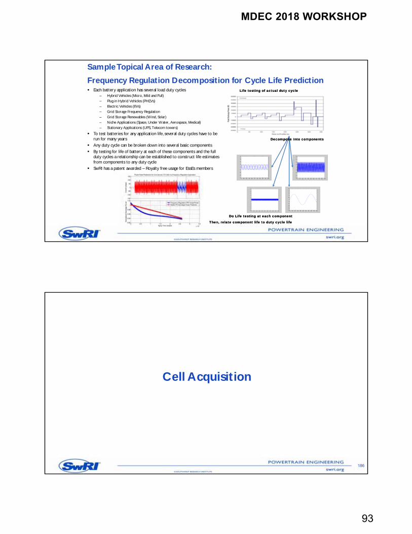
Sample Topical Area of Research:
Frequency Regulation Decomposition for Cycle Life Prediction Each battery application has several load duty cycles
– Hybrid Vehicles (Micro, Mild and Full)– Plug in Hybrid Vehicles (PHEVs)– Electric Vehicles (EVs)– Grid Storage Frequency Regulation– Grid Storage Renewables (Wind, Solar)– Niche Applications (Space, Under Water, Aerospace, Medical)– Stationary Applications (UPS, Telecom towers)
To test batteries for any application life, several duty cycles have to be run for many years
Any duty cycle can be broken down into several basic components By testing for life of battery at each of these components and the full
duty cycles a relationship can be established to construct life estimates from components to any duty cycle
SwRI has a patent awarded – Royalty free usage for EssEs members
Decompose into componentsDecompose into components
Do Life testing at each componentDo Life testing at each component
Life testing of actual duty cycleLife testing of actual duty cycle
Then, relate component life to duty cycle lifeThen, relate component life to duty cycle life
Cell Acquisition
186
MDEC 2018 WORKSHOP
94
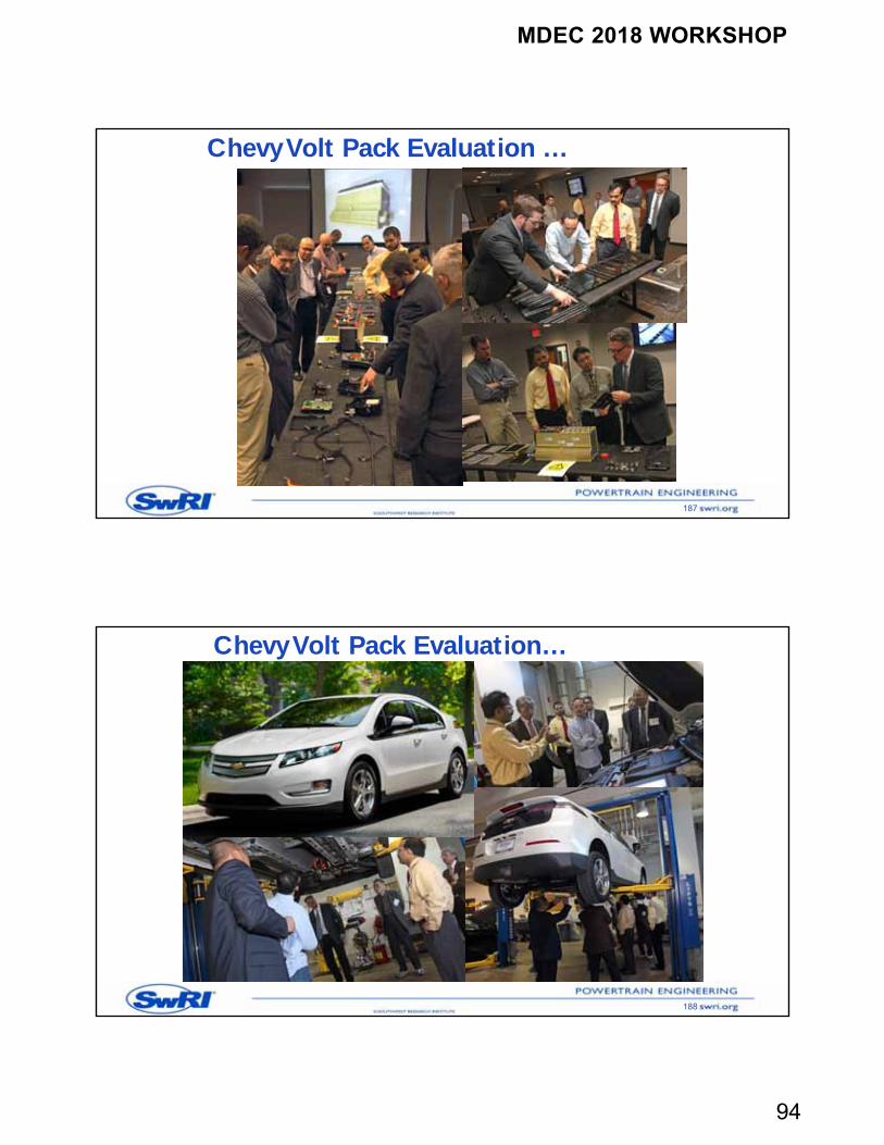
Chevy Volt Pack Evaluation …
187
Chevy Volt Pack Evaluation…
188
MDEC 2018 WORKSHOP
95
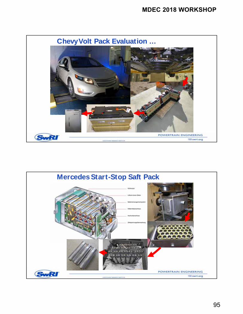
Chevy Volt Pack Evaluation …
189
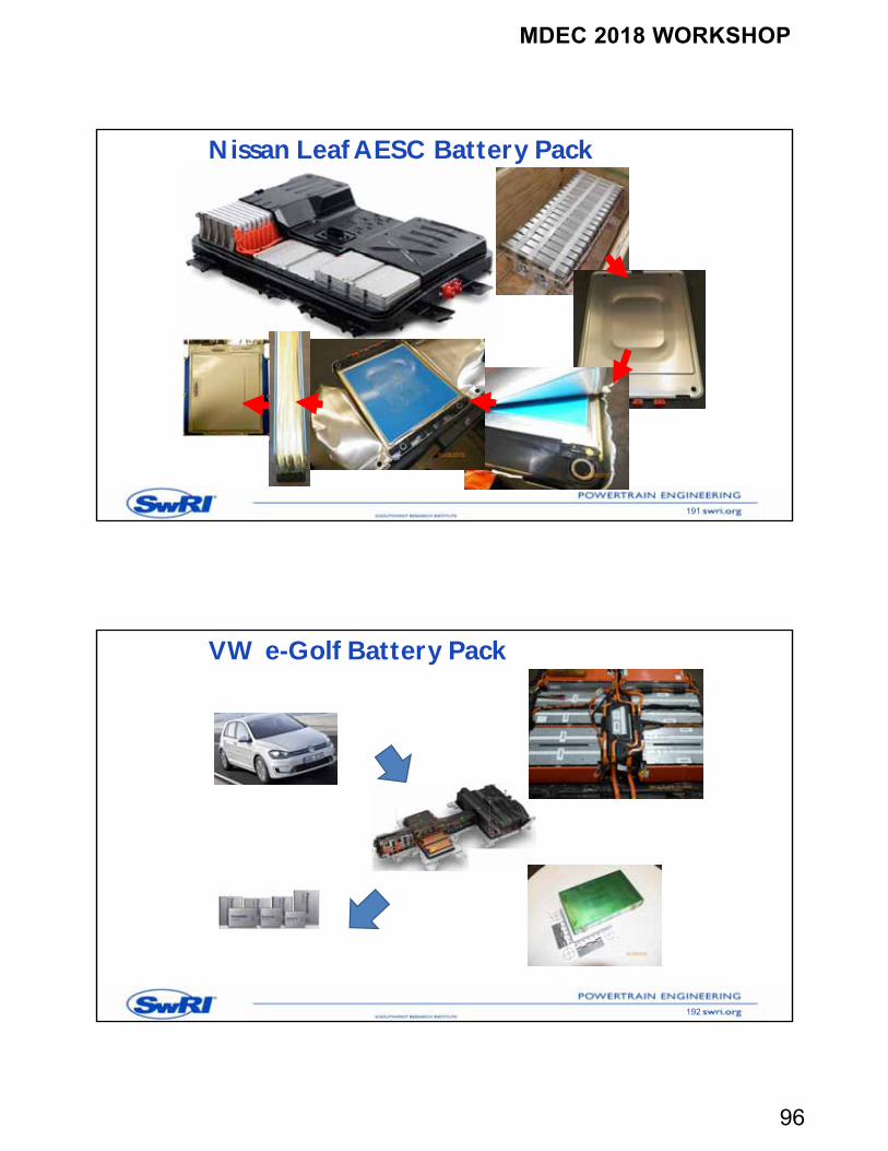
Mercedes Start-Stop Saft Pack
190
MDEC 2018 WORKSHOP
96
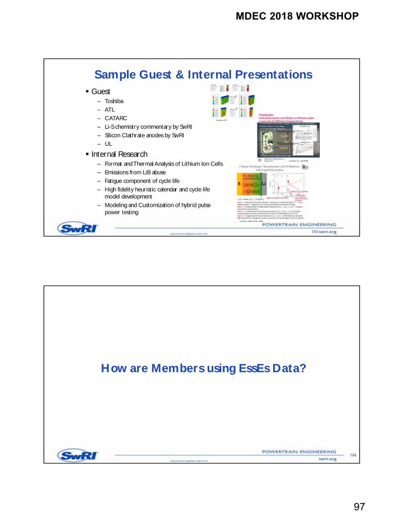
Nissan Leaf AESC Battery Pack
191
VW e-Golf Battery Pack
192
MDEC 2018 WORKSHOP
97
Sample Guest & Internal Presentations
193
Guest– Toshiba– ATL – CATARC– Li-S chemistry commentary by SwRI– Silicon Clathrate anodes by SwRI– UL
Internal Research– Format and Thermal Analysis of Lithium Ion Cells– Emissions from LiB abuse– Fatigue component of cycle life– High fidelity heuristic calendar and cycle life
model development– Modeling and Customization of hybrid pulse
power testing
Courtesy: ATL
Courtesy: UL and NTSB
Courtesy: SwRI and Dr. Miller
How are Members using EssEs Data?
194
MDEC 2018 WORKSHOP
98
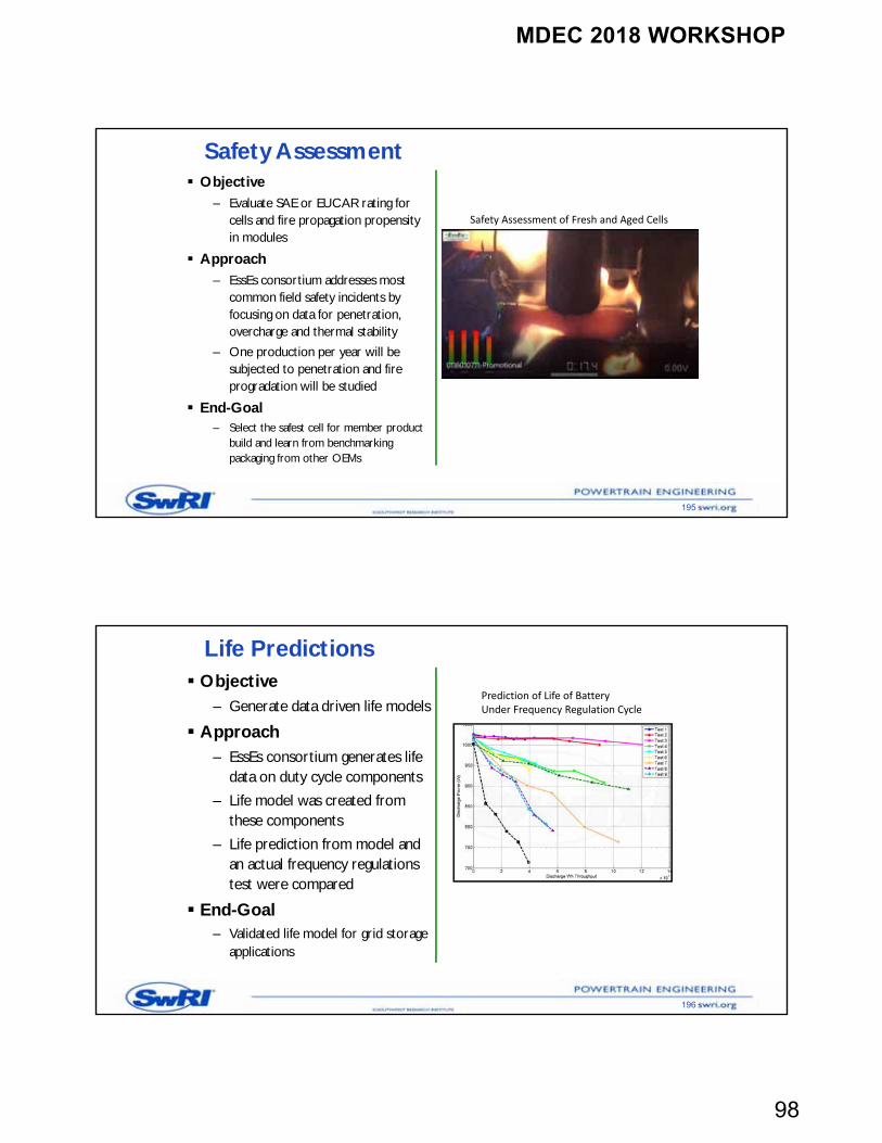
Safety Assessment
195
Objective– Evaluate SAE or EUCAR rating for
cells and fire propagation propensity in modules
Approach– EssEs consortium addresses most
common field safety incidents by focusing on data for penetration, overcharge and thermal stability
– One production per year will be subjected to penetration and fire progradation will be studied
End-Goal– Select the safest cell for member product
build and learn from benchmarking packaging from other OEMs
Safety Assessment of Fresh and Aged Cells
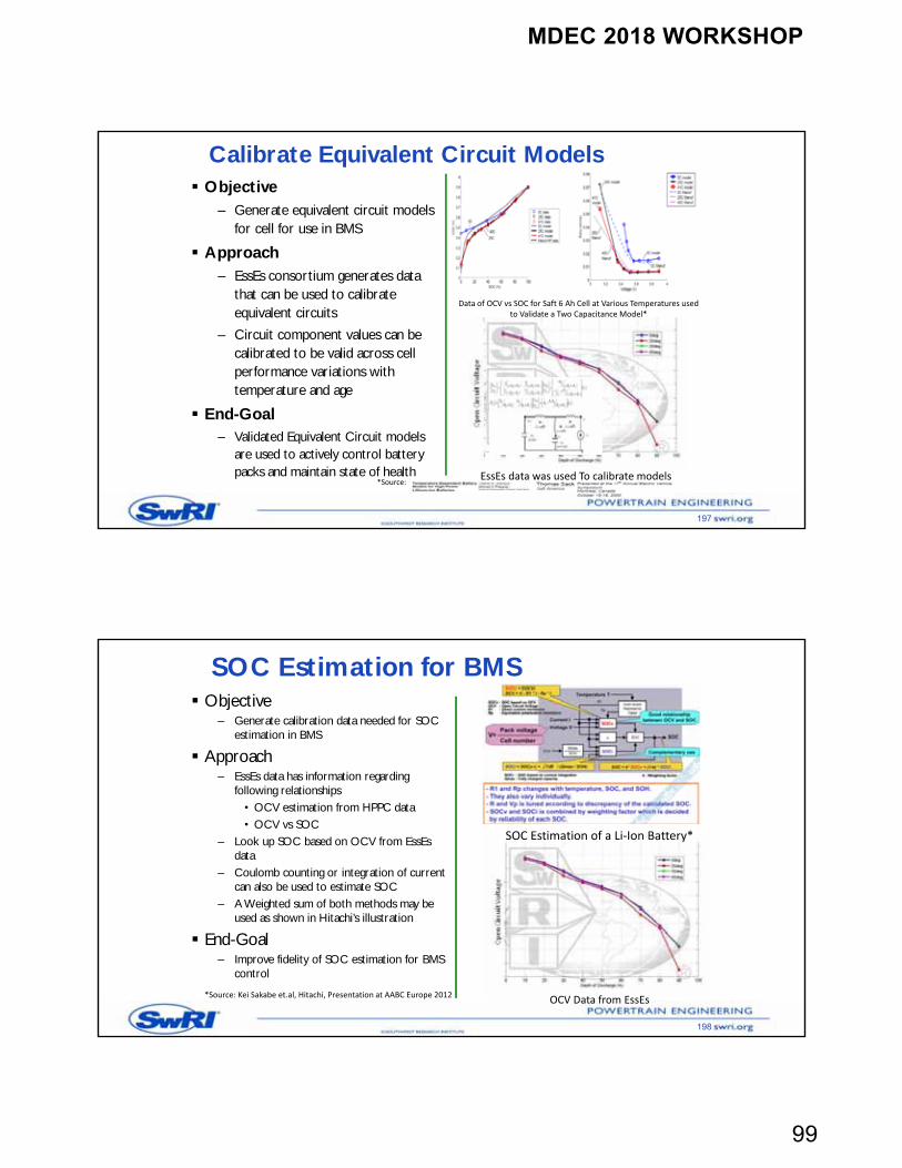
Life Predictions
196
Objective– Generate data driven life models
Approach– EssEs consortium generates life
data on duty cycle components
– Life model was created from these components
– Life prediction from model and an actual frequency regulations test were compared
End-Goal– Validated life model for grid storage
applications
Prediction of Life of Battery Under Frequency Regulation Cycle
MDEC 2018 WORKSHOP
99
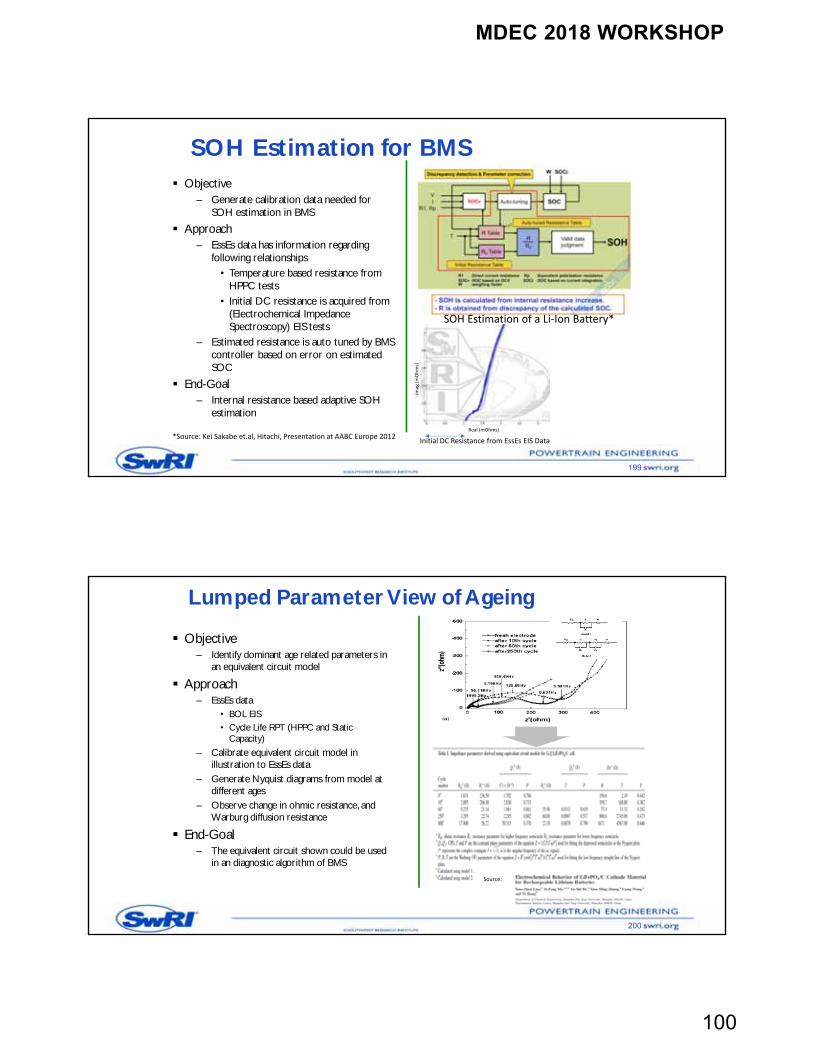
Calibrate Equivalent Circuit Models
197
Objective– Generate equivalent circuit models
for cell for use in BMS
Approach– EssEs consortium generates data
that can be used to calibrate equivalent circuits
– Circuit component values can be calibrated to be valid across cell performance variations with temperature and age
End-Goal– Validated Equivalent Circuit models
are used to actively control battery packs and maintain state of health
Data of OCV vs SOC for Saft 6 Ah Cell at Various Temperatures used to Validate a Two Capacitance Model*
EssEs data was used To calibrate models*Source:
SOC Estimation for BMS
198
Objective– Generate calibration data needed for SOC
estimation in BMS
Approach– EssEs data has information regarding
following relationships• OCV estimation from HPPC data• OCV vs SOC
– Look up SOC based on OCV from EssEs data
– Coulomb counting or integration of current can also be used to estimate SOC
– A Weighted sum of both methods may be used as shown in Hitachi’s illustration
End-Goal– Improve fidelity of SOC estimation for BMS
control
SOC Estimation of a Li‐Ion Battery*
*Source: Kei Sakabe et.al, Hitachi, Presentation at AABC Europe 2012 OCV Data from EssEs
MDEC 2018 WORKSHOP
100
SOH Estimation for BMS
199
Objective– Generate calibration data needed for
SOH estimation in BMS
Approach– EssEs data has information regarding
following relationships• Temperature based resistance from
HPPC tests• Initial DC resistance is acquired from
(Electrochemical Impedance Spectroscopy) EIS tests
– Estimated resistance is auto tuned by BMS controller based on error on estimated SOC
End-Goal– Internal resistance based adaptive SOH
estimation
SOH Estimation of a Li‐Ion Battery*
*Source: Kei Sakabe et.al, Hitachi, Presentation at AABC Europe 2012Initial DC Resistance from EssEs EIS Data
Real (mOhms)
‐Imag
(mOhms)
Lumped Parameter View of Ageing
200
Objective– Identify dominant age related parameters in
an equivalent circuit model
Approach– EssEs data
• BOL EIS• Cycle Life RPT (HPPC and Static
Capacity)
– Calibrate equivalent circuit model in illustration to EssEs data
– Generate Nyquist diagrams from model at different ages
– Observe change in ohmic resistance, and Warburg diffusion resistance
End-Goal– The equivalent circuit shown could be used
in an diagnostic algorithm of BMS
Source:
MDEC 2018 WORKSHOP
101
Aging Metrics Identificationand Quantification through Heuristic Patterns
201
Problem– Significant amount of cell-aging
data needs to be deciphered
Approach– Post-process EssEs cycle life data– Examine specific cycling
parameters such as hysteresis– Identify key features of the
behavior that correlates to cycling
End-Goal– Find a feature or combination of
features that correlates to cycle life degradation
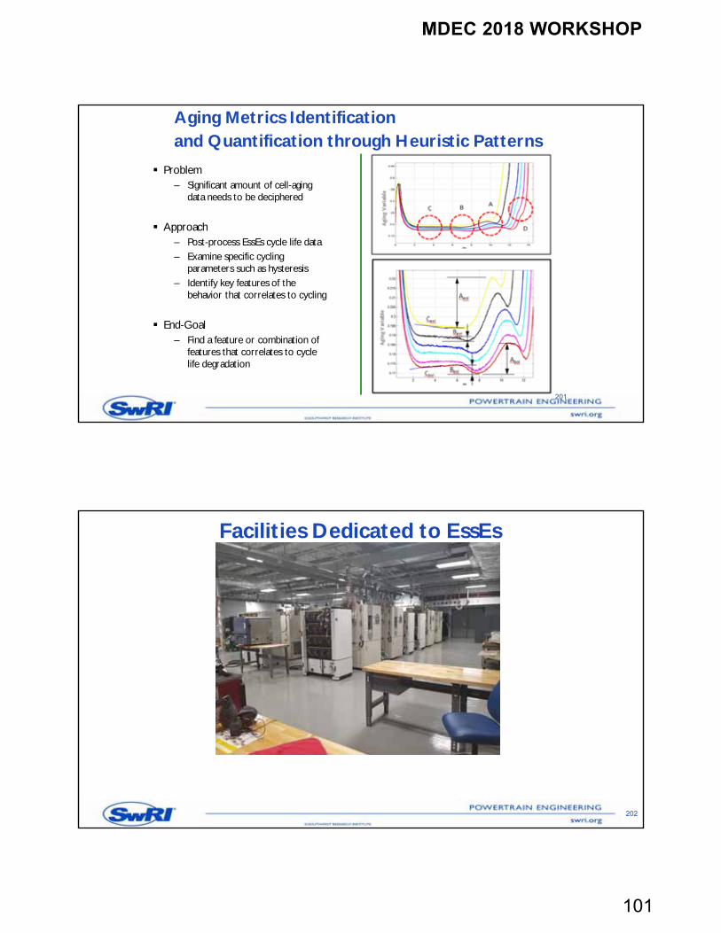
Facilities Dedicated to EssEs
202
MDEC 2018 WORKSHOP
102
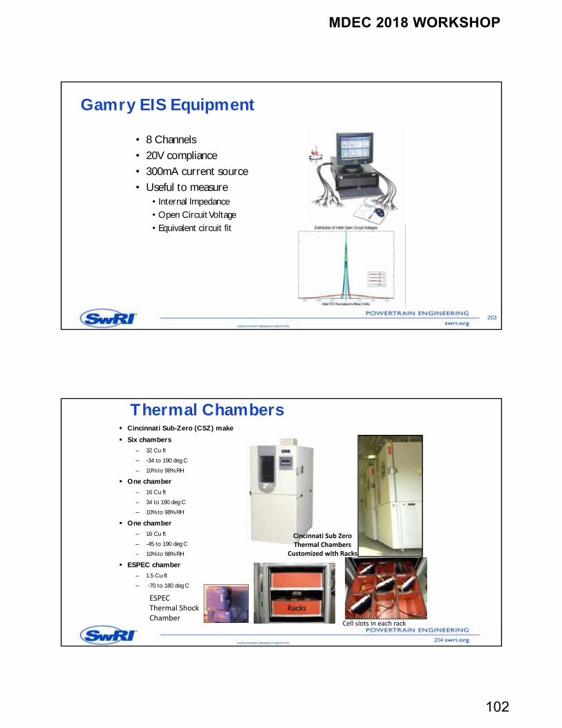
Gamry EIS Equipment
203
• 8 Channels• 20V compliance• 300mA current source• Useful to measure
• Internal Impedance• Open Circuit Voltage• Equivalent circuit fit
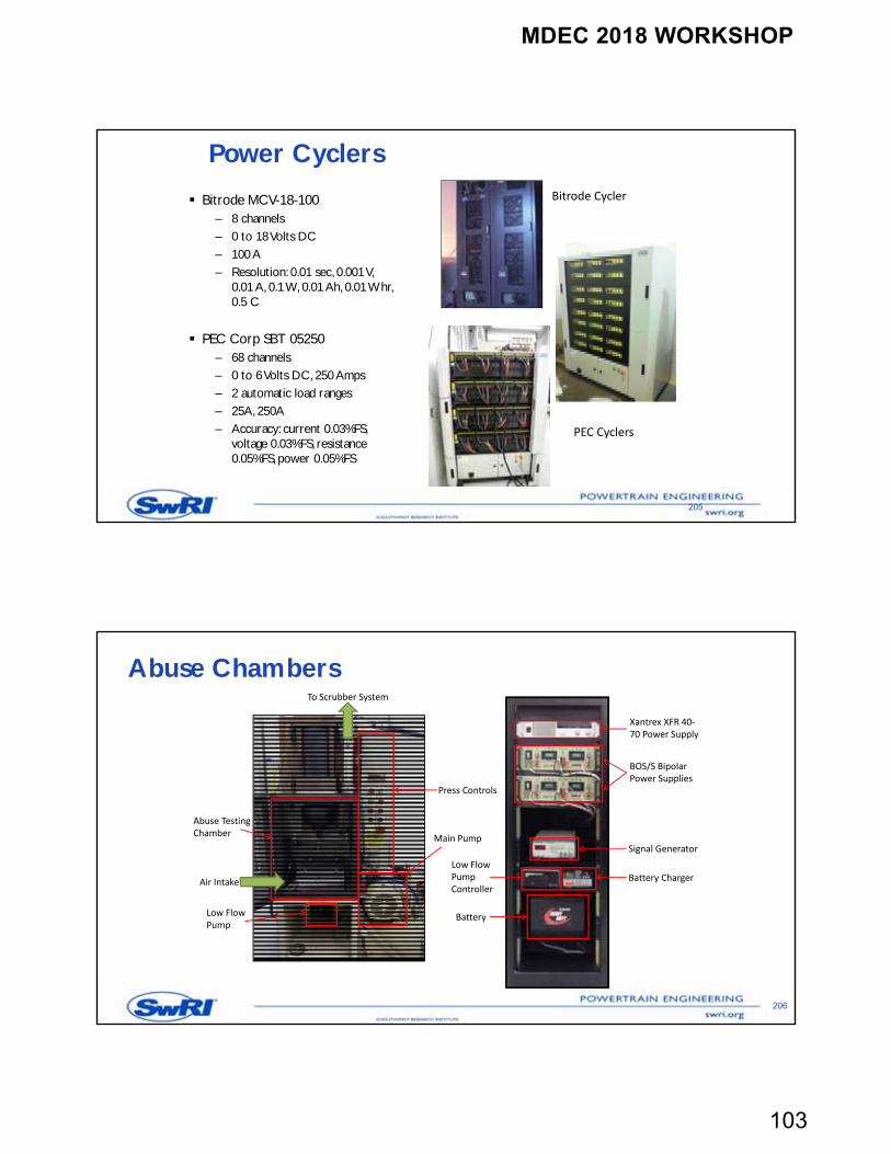
Thermal Chambers
204
Cincinnati Sub-Zero (CSZ) make
Six chambers
– 32 Cu ft
– -34 to 190 deg C
– 10% to 98% RH
One chamber
– 16 Cu ft
– 34 to 190 deg C
– 10% to 98% RH
One chamber
– 16 Cu ft
– -45 to 190 deg C
– 10% to 98% RH
ESPEC chamber
– 1.5 Cu-ft
– -70 to 180 deg C
Racks
Cell slots in each rack
ESPECThermal ShockChamber
Cincinnati Sub ZeroThermal Chambers
Customized with Racks
MDEC 2018 WORKSHOP
103
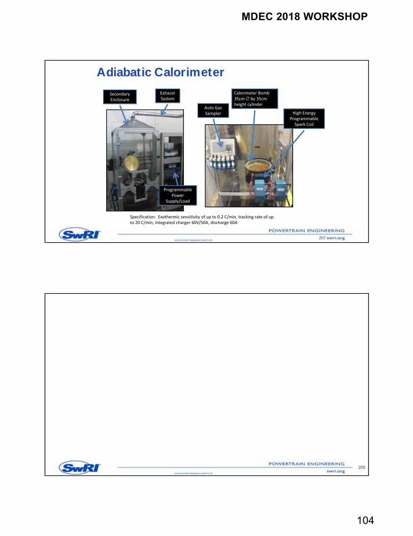
Power Cyclers
205
Bitrode MCV-18-100– 8 channels– 0 to 18 Volts DC– 100 A– Resolution: 0.01 sec, 0.001 V,
0.01 A, 0.1 W, 0.01 Ah, 0.01 Whr, 0.5 C
PEC Corp SBT 05250– 68 channels– 0 to 6 Volts DC, 250 Amps– 2 automatic load ranges– 25A, 250A– Accuracy: current 0.03%FS,
voltage 0.03%FS, resistance 0.05%FS, power 0.05%FS
PEC Cyclers
Bitrode Cycler
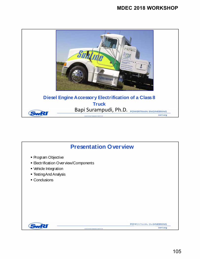
Abuse Chambers
206
BOS/S BipolarPower Supplies
Xantrex XFR 40‐70 Power Supply
Signal Generator
Low Flow Pump Controller
Battery Charger
Battery
Press Controls
Main Pump
Abuse Testing Chamber
Low Flow Pump
Air Intake
To Scrubber System
MDEC 2018 WORKSHOP
104
Adiabatic Calorimeter
207
Auto Gas Sampler
Calorimeter Bomb 35cm by 35cm height cylinder
High Energy Programmable Spark Coil
Exhaust System
Programmable Power
Supply/Load
Secondary Enclosure
Specification: Exothermic sensitivity of up to 0.2 C/min, tracking rate of up to 20 C/min, integrated charger 60V/50A, discharge 60A
208
MDEC 2018 WORKSHOP
105
Diesel Engine Accessory Electrification of a Class 8 Truck
Bapi Surampudi, Ph.D.
Presentation Overview
Program Objective Electrification Overview/Components Vehicle Integration Testing And Analysis Conclusions
2005-01-0016
MDEC 2018 WORKSHOP
106
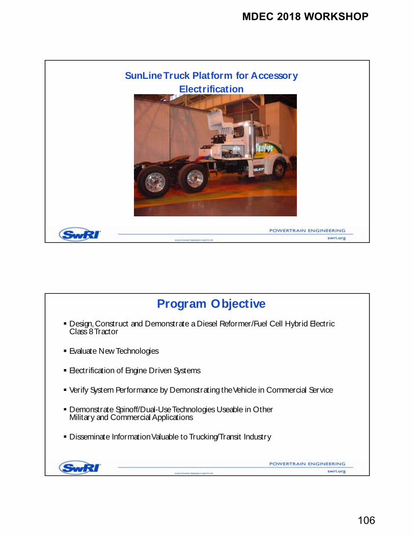
SunLine Truck Platform for Accessory Electrification
Program Objective
Design, Construct and Demonstrate a Diesel Reformer/Fuel Cell Hybrid Electric Class 8 Tractor
Evaluate New Technologies
Electrification of Engine Driven Systems
Verify System Performance by Demonstrating the Vehicle in Commercial Service
Demonstrate Spinoff/Dual-Use Technologies Useable in OtherMilitary and Commercial Applications
Disseminate Information Valuable to Trucking/Transit Industry
MDEC 2018 WORKSHOP
107
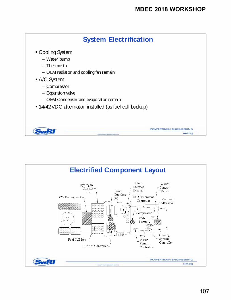
System Electrification
Cooling System– Water pump– Thermostat– OEM radiator and cooling fan remain
A/C System– Compressor– Expansion valve– OEM Condenser and evaporator remain
14/42 VDC alternator installed (as fuel cell backup)
Electrified Component Layout
MDEC 2018 WORKSHOP
108
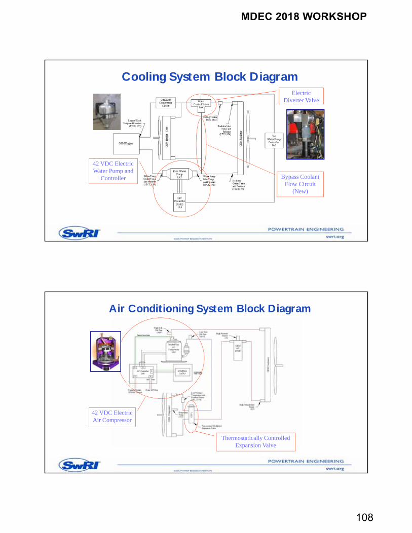
Cooling System Block Diagram
42 VDC Electric Water Pump and
Controller
Electric Diverter Valve
Bypass Coolant Flow Circuit
(New)
Air Conditioning System Block Diagram
Thermostatically Controlled Expansion Valve
42 VDC Electric Air Compressor
MDEC 2018 WORKSHOP
109
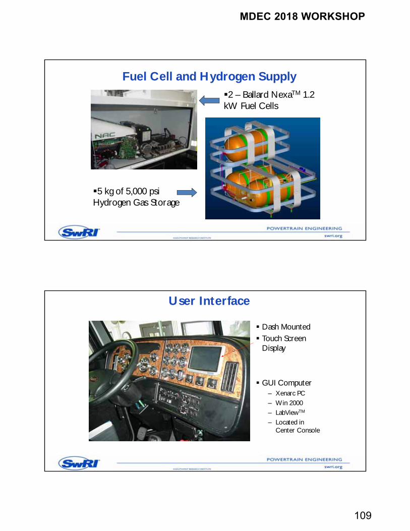
Fuel Cell and Hydrogen Supply
5 kg of 5,000 psi Hydrogen Gas Storage
2 – Ballard NexaTM 1.2 kW Fuel Cells
User Interface
Dash Mounted Touch Screen
Display
GUI Computer– Xenarc PC– Win 2000– LabViewTM
– Located in Center Console
MDEC 2018 WORKSHOP
110
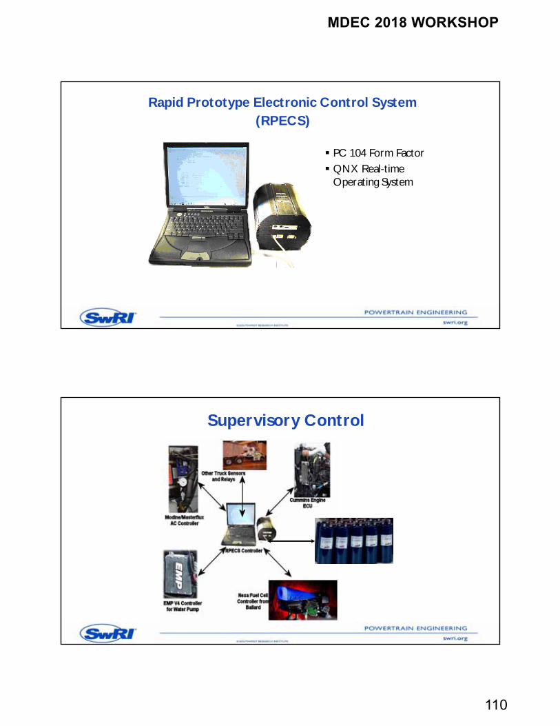
Rapid Prototype Electronic Control System(RPECS)
PC 104 Form Factor QNX Real-time
Operating System
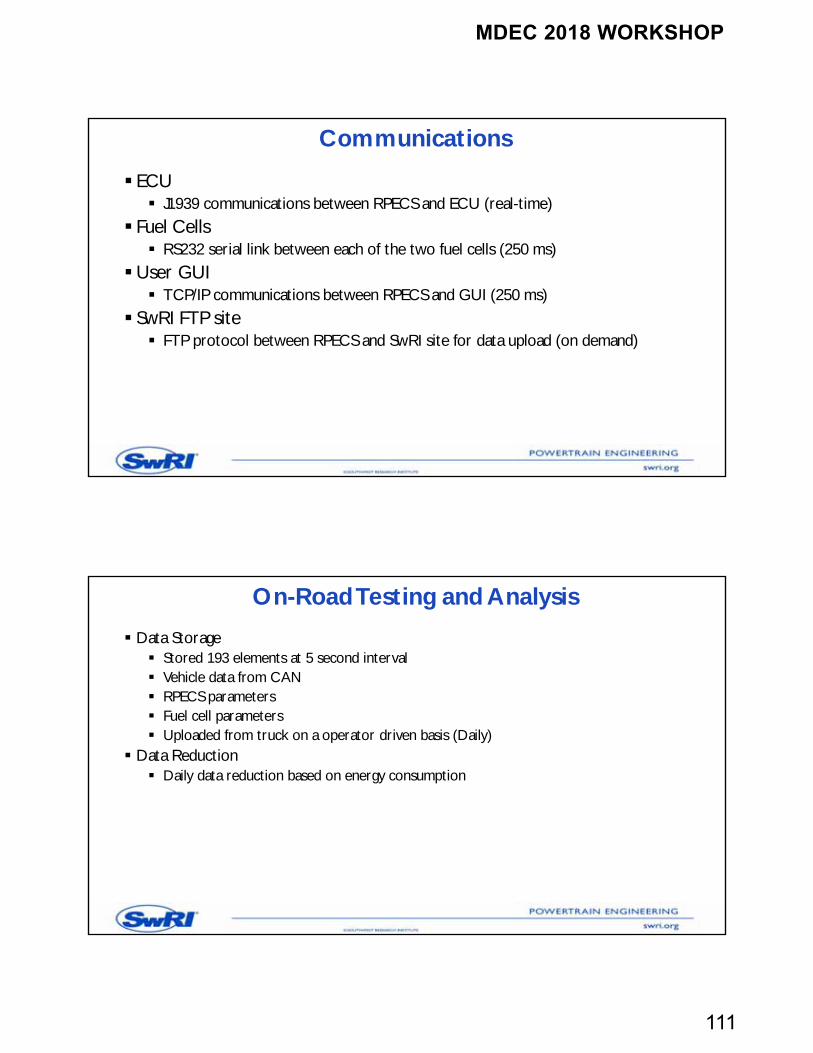
Supervisory Control
MDEC 2018 WORKSHOP
111
Communications
ECU J1939 communications between RPECS and ECU (real-time)
Fuel Cells RS232 serial link between each of the two fuel cells (250 ms)
User GUI TCP/IP communications between RPECS and GUI (250 ms)
SwRI FTP site FTP protocol between RPECS and SwRI site for data upload (on demand)
On-Road Testing and Analysis
Data Storage Stored 193 elements at 5 second interval Vehicle data from CAN RPECS parameters Fuel cell parameters Uploaded from truck on a operator driven basis (Daily)
Data Reduction Daily data reduction based on energy consumption
MDEC 2018 WORKSHOP
112
Energy Analysis Assumptions
Cooling System Mechanical water pump calculations No consideration for thermostat
AC System Mechanical compressor energy NOT considered AC energy savings based on engine fan On/Off
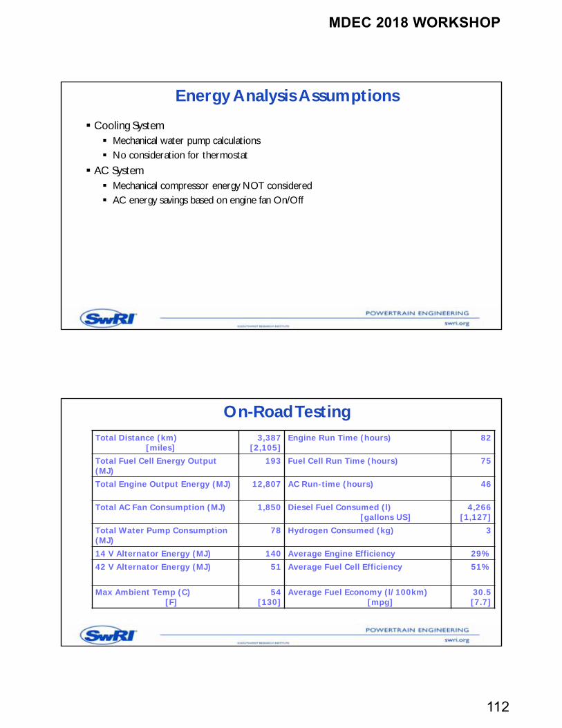
On-Road TestingTotal Distance (km)
[miles] 3,387
[2,105]Engine Run Time (hours) 82
Total Fuel Cell Energy Output (MJ)
193 Fuel Cell Run Time (hours) 75
Total Engine Output Energy (MJ) 12,807 AC Run-time (hours) 46
Total AC Fan Consumption (MJ) 1,850 Diesel Fuel Consumed (l)[gallons US]
4,266[1,127]
Total Water Pump Consumption (MJ)
78 Hydrogen Consumed (kg) 3
14 V Alternator Energy (MJ) 140 Average Engine Efficiency 29%42 V Alternator Energy (MJ) 51 Average Fuel Cell Efficiency 51%
Max Ambient Temp (C)[F]
54[130]
Average Fuel Economy (l/100km)[mpg]
30.5[7.7]
MDEC 2018 WORKSHOP
113
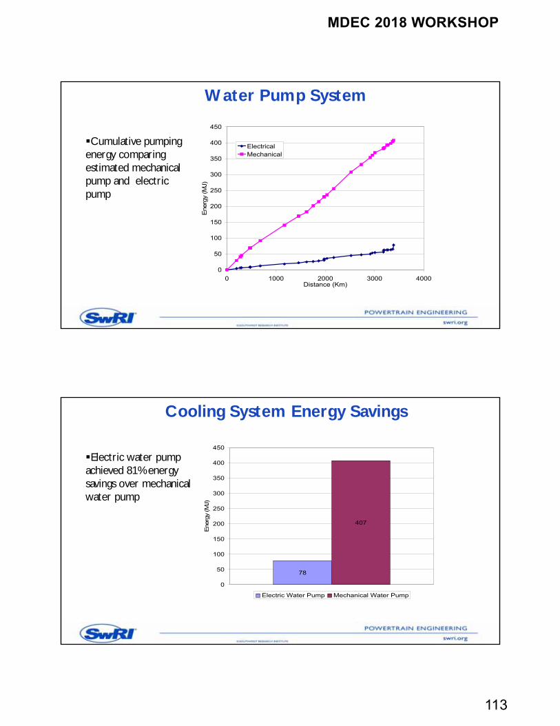
Water Pump System
Cumulative pumping energy comparing estimated mechanical pump and electric pump
0
50
100
150
200
250
300
350
400
450
0 1000 2000 3000 4000Distance (Km)
Ene
rgy
(MJ)
ElectricalMechanical
Cooling System Energy Savings
Electric water pump achieved 81% energy savings over mechanical water pump
78
407
0
50
100
150
200
250
300
350
400
450
Ene
rgy
(MJ)
Electric Water Pump Mechanical Water Pump
MDEC 2018 WORKSHOP
114
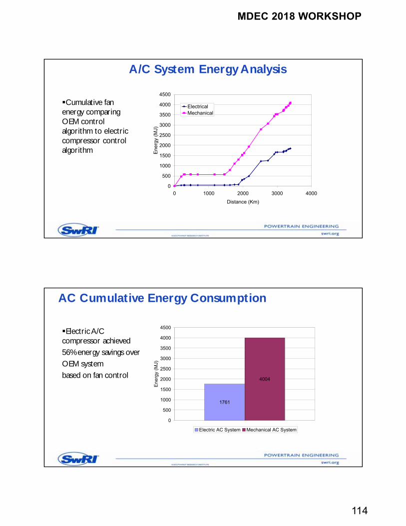
A/C System Energy Analysis
Cumulative fan energy comparing OEM control algorithm to electric compressor control algorithm
0
500
1000
1500
2000
2500
3000
3500
4000
4500
0 1000 2000 3000 4000
Distance (Km)
Ene
rgy
(MJ)
ElectricalMechanical
AC Cumulative Energy Consumption
Electric A/C compressor achieved56% energy savings overOEM systembased on fan control
1761
4004
0
500
1000
1500
2000
2500
3000
3500
4000
4500
En
erg
y (M
J)
Electric AC System Mechanical AC System
MDEC 2018 WORKSHOP
115
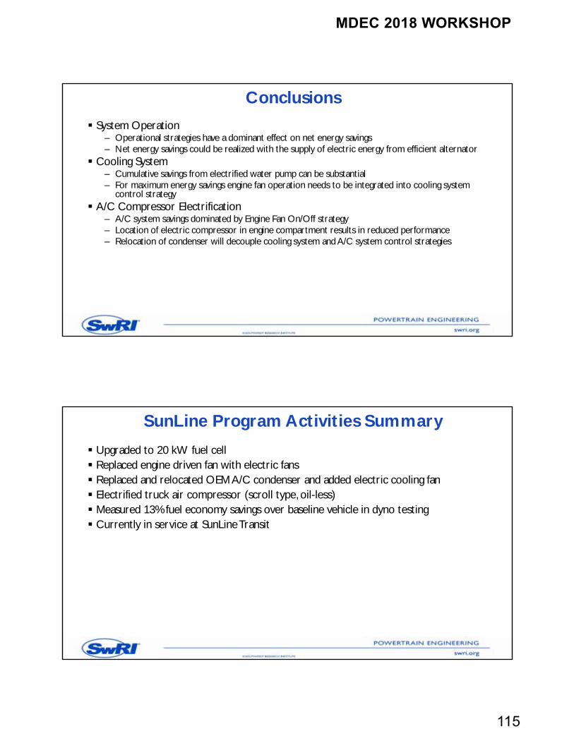
Conclusions
System Operation– Operational strategies have a dominant effect on net energy savings– Net energy savings could be realized with the supply of electric energy from efficient alternator
Cooling System– Cumulative savings from electrified water pump can be substantial– For maximum energy savings engine fan operation needs to be integrated into cooling system
control strategy A/C Compressor Electrification
– A/C system savings dominated by Engine Fan On/Off strategy– Location of electric compressor in engine compartment results in reduced performance– Relocation of condenser will decouple cooling system and A/C system control strategies
SunLine Program Activities Summary
Upgraded to 20 kW fuel cell Replaced engine driven fan with electric fans Replaced and relocated OEM A/C condenser and added electric cooling fan Electrified truck air compressor (scroll type, oil-less) Measured 13% fuel economy savings over baseline vehicle in dyno testing Currently in service at SunLine Transit
MDEC 2018 WORKSHOP
116
Acknowledgements
US Army TARDEC NAC SunLine Transit Agency Engineered Machine Products Modine Masterflux Peterbilt Cummins CE Niehoff & Co
232
MDEC 2018 WORKSHOP
117
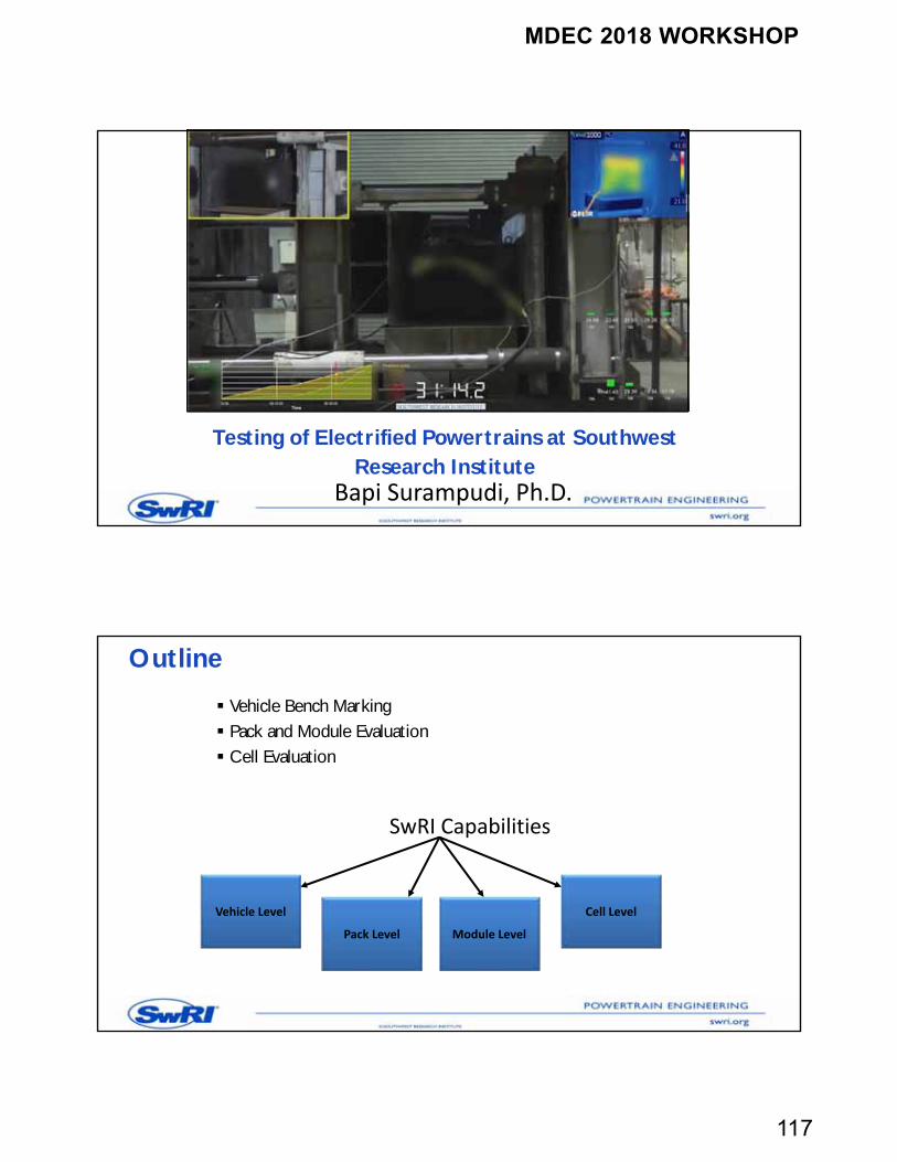
Testing of Electrified Powertrains at Southwest Research Institute
Bapi Surampudi, Ph.D.
Outline
Vehicle Bench Marking Pack and Module Evaluation Cell Evaluation
Vehicle Level
Pack Level Module Level
Cell Level
SwRI Capabilities
MDEC 2018 WORKSHOP
118
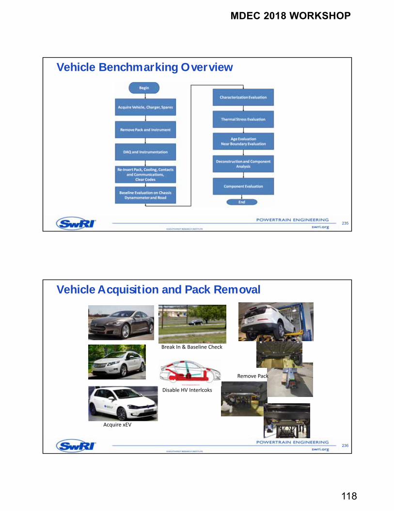
Vehicle Benchmarking Overview
235
Vehicle Acquisition and Pack Removal
236
Acquire xEV
Remove Pack
Break In & Baseline Check
Disable HV Interlcoks
MDEC 2018 WORKSHOP
119
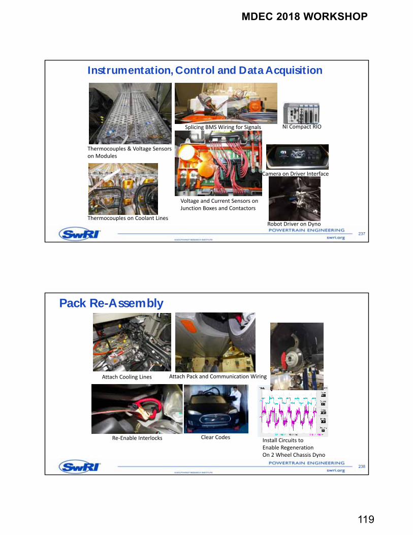
Instrumentation, Control and Data Acquisition
237
Thermocouples & Voltage Sensors on Modules
Splicing BMS Wiring for Signals
Thermocouples on Coolant Lines
Voltage and Current Sensors onJunction Boxes and Contactors
Camera on Driver Interface
Robot Driver on Dyno
NI Compact RIO
Pack Re-Assembly
238
Attach Cooling Lines
Re‐Enable Interlocks
Attach Pack and Communication Wiring
Clear Codes Install Circuits toEnable RegenerationOn 2 Wheel Chassis Dyno
MDEC 2018 WORKSHOP
120
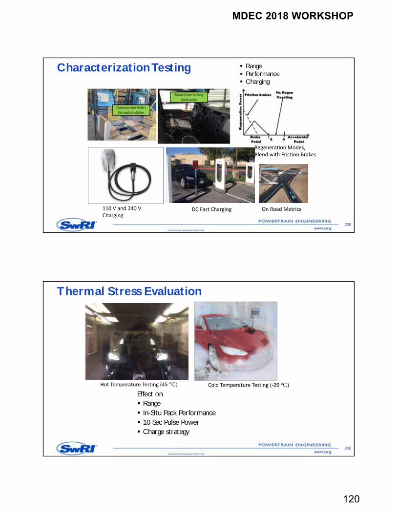
Characterization Testing Range Performance Charging
239
110 V and 240 VCharging
DC Fast Charging
Regeneration Modes,Blend with Friction Brakes
On Road Metrics
Thermal Stress Evaluation
Effect on Range In-Situ Pack Performance 10 Sec Pulse Power Charge strategy
240
Hot Temperature Testing (45 °C) Cold Temperature Testing (‐20 °C)
MDEC 2018 WORKSHOP
121
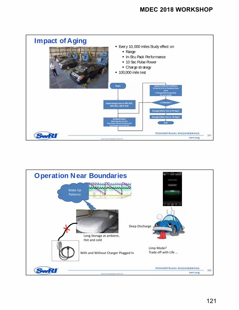
Impact of Aging
241
Every 10, 000 miles Study effect on Range In-Situ Pack Performance 10 Sec Pulse Power Charge strategy
100,000 mile test
Operation Near Boundaries
242
Wake UpPatterns
Long Storage at ambient,Hot and cold
Deep Discharge
With and Without Charger Plugged In
Limp Mode?Trade off with Life …
MDEC 2018 WORKSHOP
122
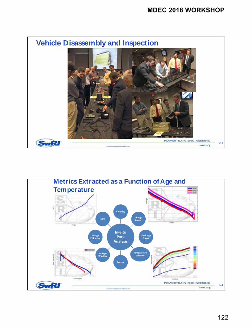
Vehicle Disassembly and Inspection
243
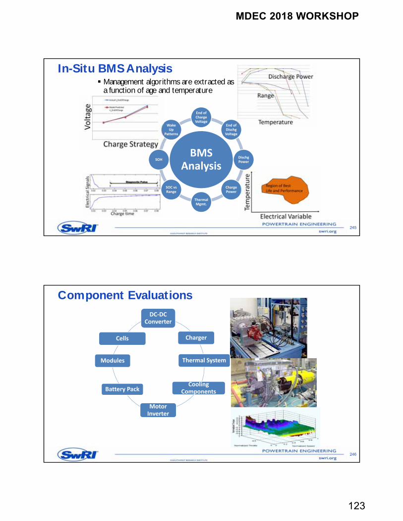
Metrics Extracted as a Function of Age and Temperature
244
In‐Situ Pack
Analysis
Capacity
Charge Power
Discharge Power
Temperature Window
Energy
Voltage Window
Energy Efficiency
OCV
MDEC 2018 WORKSHOP
123
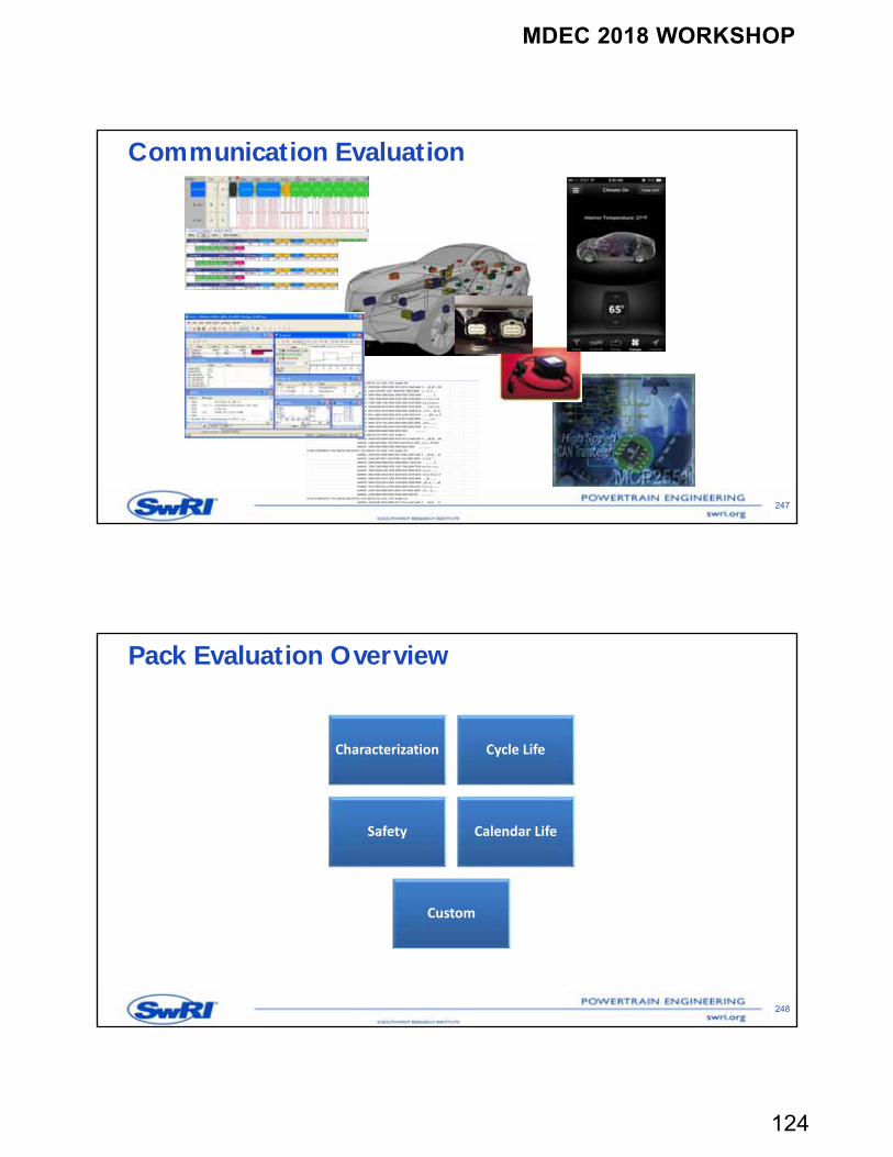
In-Situ BMS Analysis Management algorithms are extracted as
a function of age and temperature
245
BMS Analysis
End of Charge Voltage
End of Dischg Voltage
Dischg Power
Charge Power
Thermal Mgmt.
SOC vsRange
SOH
Wake Up
Patterns
Component Evaluations
246
DC‐DC Converter
Charger
Thermal System
Cooling Components
Motor Inverter
Battery Pack
Modules
Cells
MDEC 2018 WORKSHOP
124
Communication Evaluation
247
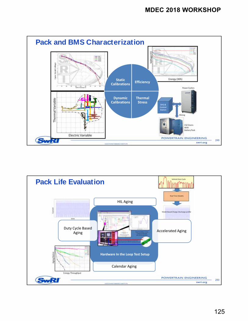
Pack Evaluation Overview
248
Characterization Cycle Life
Safety Calendar Life
Custom
MDEC 2018 WORKSHOP
125
Pack and BMS Characterization
249
Efficiency
Thermal Stress
Dynamic Calibrations
Static Calibrations
HIL Aging
Accelerated AgingDuty Cycle Based
Aging
Calendar Aging
Pack Life Evaluation
250
Hardware In the Loop Test Setup
MDEC 2018 WORKSHOP
126
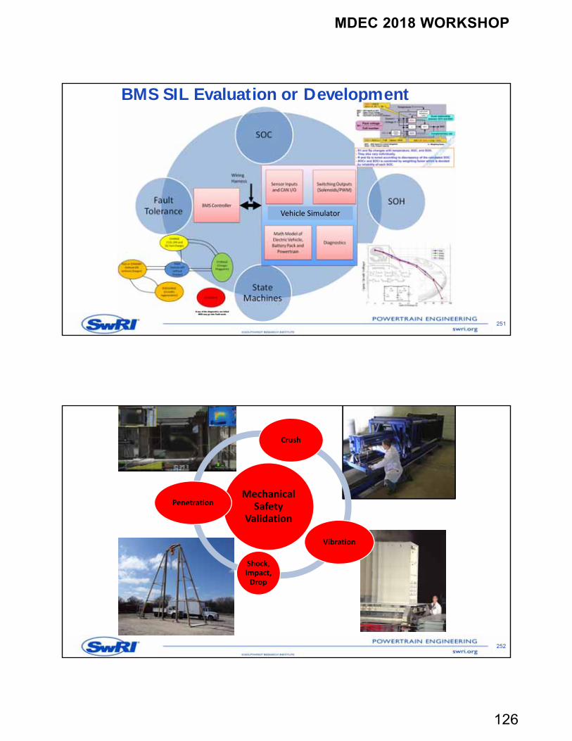
SOC
SOH
State Machines
Fault Tolerance
BMS SIL Evaluation or Development
251
Vehicle Simulator
252
Mechanical Safety
Validation
Crush
Vibration
Shock, Impact, Drop
Penetration
MDEC 2018 WORKSHOP
127
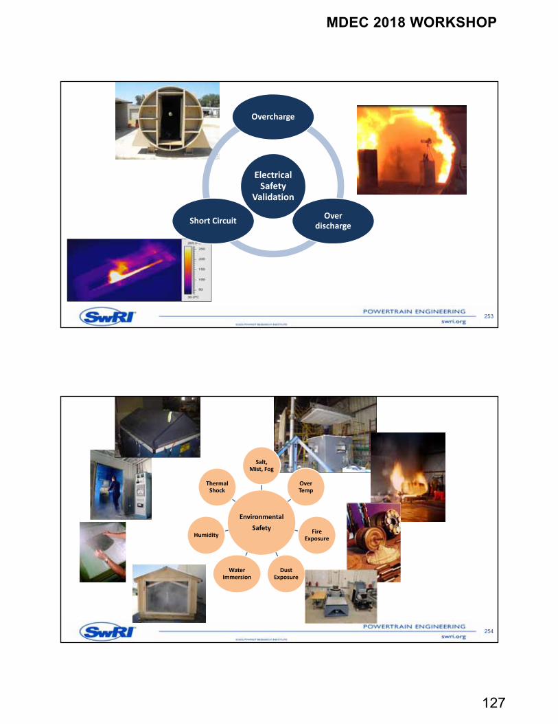
253
Electrical Safety
Validation
Overcharge
Over discharge
Short Circuit
254
Environmental
Safety
Salt, Mist, Fog
Over Temp
Fire Exposure
Dust Exposure
Water Immersion
Humidity
Thermal Shock
MDEC 2018 WORKSHOP
128
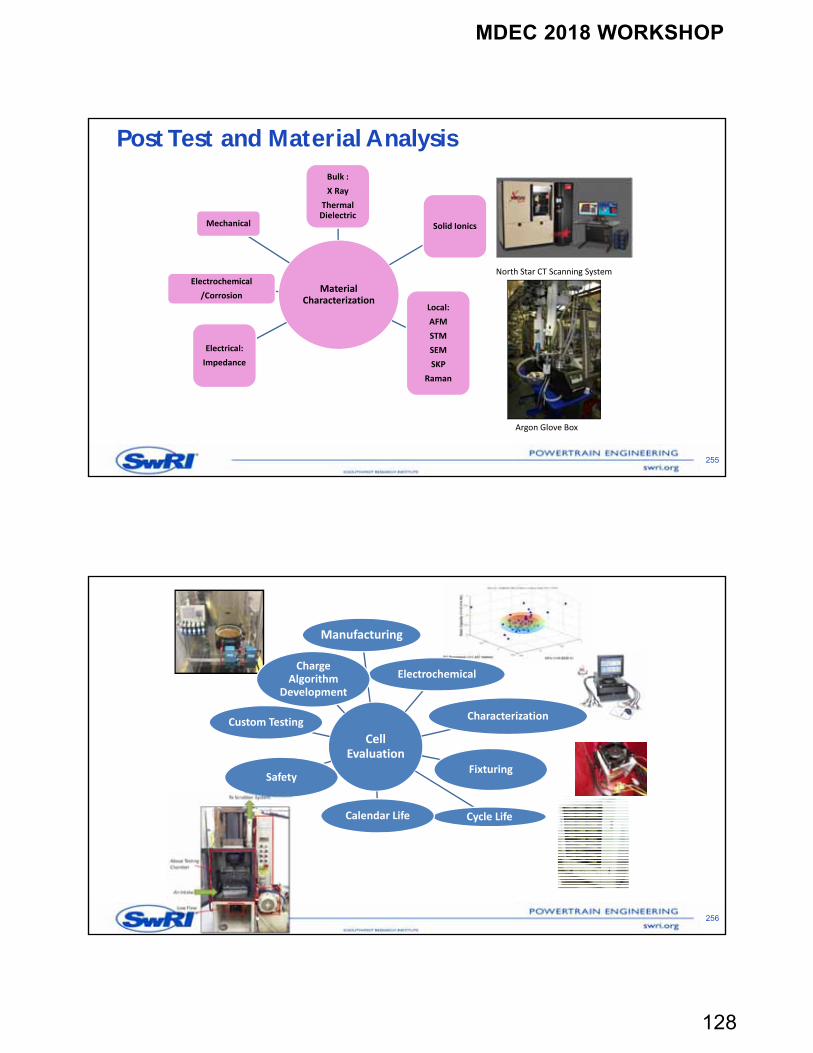
Post Test and Material Analysis
255
North Star CT Scanning System
Argon Glove Box
Material Characterization
Bulk :
X Ray
Thermal Dielectric
Solid Ionics
Local:
AFM
STM
SEM
SKP
Raman
Electrical:
Impedance
Electrochemical
/Corrosion
Mechanical
256
Cell Evaluation
Manufacturing
Electrochemical
Characterization
Fixturing
Cycle LifeCalendar Life
Safety
Custom Testing
Charge Algorithm
Development
MDEC 2018 WORKSHOP
129
Summary
SwRI can support customer with cell, module and pack development and evaluation SwRI can assist in BMS development or evaluation SwRI can perform xEV benchmarking for aiding and accelerating product
development SwRI can build complete vehicle prototypes of light duty, heavy duty and commercial
off high way vehicles
257
Contact Information
258
Bapi Surampudi– Desk: (001)-210-522-3278– Cell: (001)-210-249-6265– [email protected]
MDEC 2018 WORKSHOP
130
October 2018
Enabling Technologies -Diesel through hybrid
Evelynn Stirling
260
Acknowledgements
Thank you to the following individuals for their contributions to this presentation:-
Joan Wills Technical Executive Director, Cummins Inc.
Chris Brown Off-Highway Aftermarket Director, Cummins Inc.
Jeremy Harsin Industrial Global Product Manager, Cummins Inc.
260
MDEC 2018 WORKSHOP
131
261
Enabling technology
261
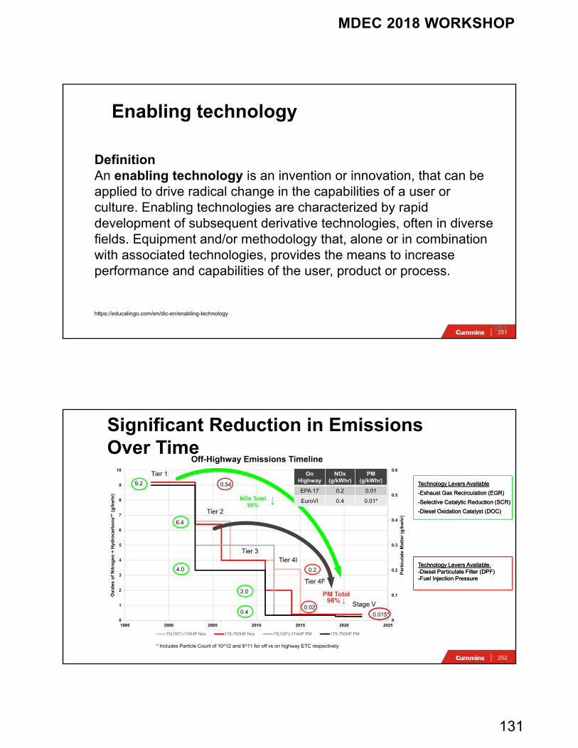
DefinitionAn enabling technology is an invention or innovation, that can be applied to drive radical change in the capabilities of a user or culture. Enabling technologies are characterized by rapid development of subsequent derivative technologies, often in diverse fields. Equipment and/or methodology that, alone or in combination with associated technologies, provides the means to increase performance and capabilities of the user, product or process.
https://educalingo.com/en/dic-en/enabling-technology
262
0
0.1
0.2
0.3
0.4
0.5
0.6
0
1
2
3
4
5
6
7
8
9
10
1995 2000 2005 2010 2015 2020 2025
Par
ticu
late
Mat
ter
(g/k
wh
r)
Oxi
des
of
Nit
rog
en +
Hyd
roca
rbo
ns*
* (g
/kw
hr)
Off-Highway Emissions Timeline
75(100*)-174HP Nox 175-750HP Nox 75(100*)-174HP PM 175-750HP PM
Significant Reduction in Emissions Over Time
PM Total96% ↓
Tier 1
Tier 2
Tier 3
Tier 4F
Stage V
NOx Total96%
↓
0.02
0.2
0.015*
OnHighway
NOx (g/kWhr)
PM (g/kWhr)
EPA 17 0.2 0.01
EuroVI 0.4 0.01*
* Includes Particle Count of 10^12 and 6^11 for off vs on highway ETC respectively
0.549.2
6.4
4.0
2.0
Tier 4I
0.4
Technology Levers Available
-Exhaust Gas Recirculation (EGR)
-Selective Catalytic Reduction (SCR)
-Diesel Oxidation Catalyst (DOC)
Technology Levers Available
-Exhaust Gas Recirculation (EGR)
-Selective Catalytic Reduction (SCR)
-Diesel Oxidation Catalyst (DOC)
Technology Levers Available.-Diesel Particulate Filter (DPF)-Fuel Injection Pressure
Technology Levers Available.-Diesel Particulate Filter (DPF)-Fuel Injection Pressure
MDEC 2018 WORKSHOP
132
263
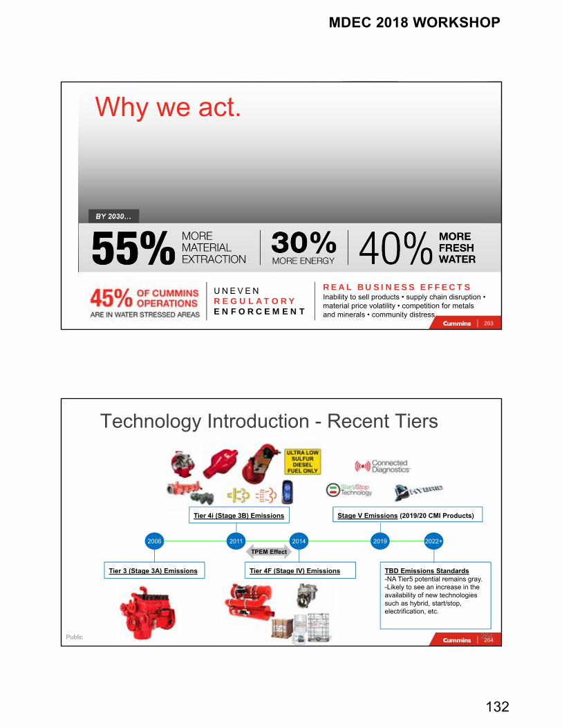
BY 2030…
REAL BUSINESS EFFECTS Inability to sell products • supply chain disruption • material price volatility • competition for metals and minerals • community distress
Why we act.
U N E V E NR E G U L AT O RYE N F O R C E M E N T
264264Public
Technology Introduction - Recent Tiers
Tier 3 (Stage 3A) Emissions
2006 2011 2014 2019 2022+
Tier 4i (Stage 3B) Emissions
Tier 4F (Stage IV) Emissions
TPEM Effect
Stage V Emissions (2019/20 CMI Products)
TBD Emissions Standards-NA Tier5 potential remains gray.-Likely to see an increase in the availability of new technologies such as hybrid, start/stop, electrification, etc.
MDEC 2018 WORKSHOP
133
265
0
1,000
2,000
3,000
4,000
5,000
6,000
7,000
8,000
Q1 Q2 Q3 Q4 Q1 Q2 Q3 Q4 Q1
2015 2016 2017
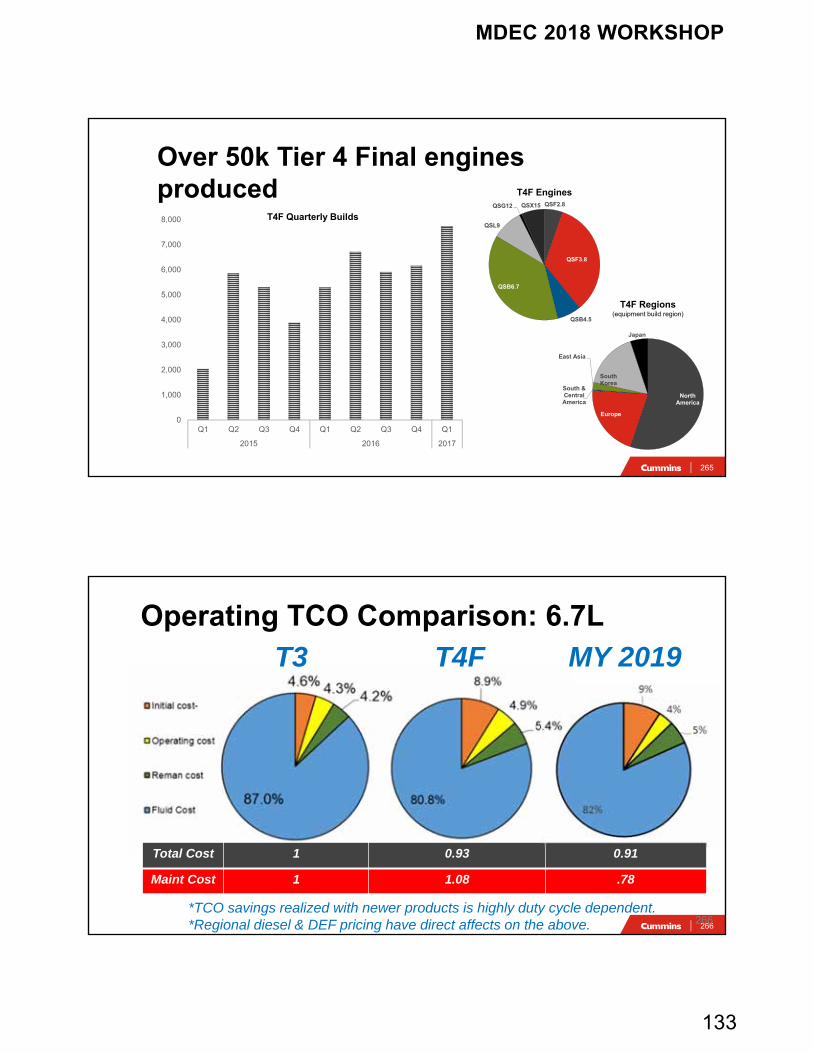
Over 50k Tier 4 Final engines produced
QSF2.8
QSF3.8
QSB4.5
QSB6.7
QSL9
QSG12 QSX15
North America
Europe
South & Central America
East Asia
South Korea
Japan
T4F Quarterly Builds
T4F Regions(equipment build region)
T4F Engines
266
Operating TCO Comparison: 6.7L
266
T3 T4F MY 2019
Total Cost 1 0.93 0.91
Maint Cost 1 1.08 .78
*TCO savings realized with newer products is highly duty cycle dependent.*Regional diesel & DEF pricing have direct affects on the above.
MDEC 2018 WORKSHOP
134
267
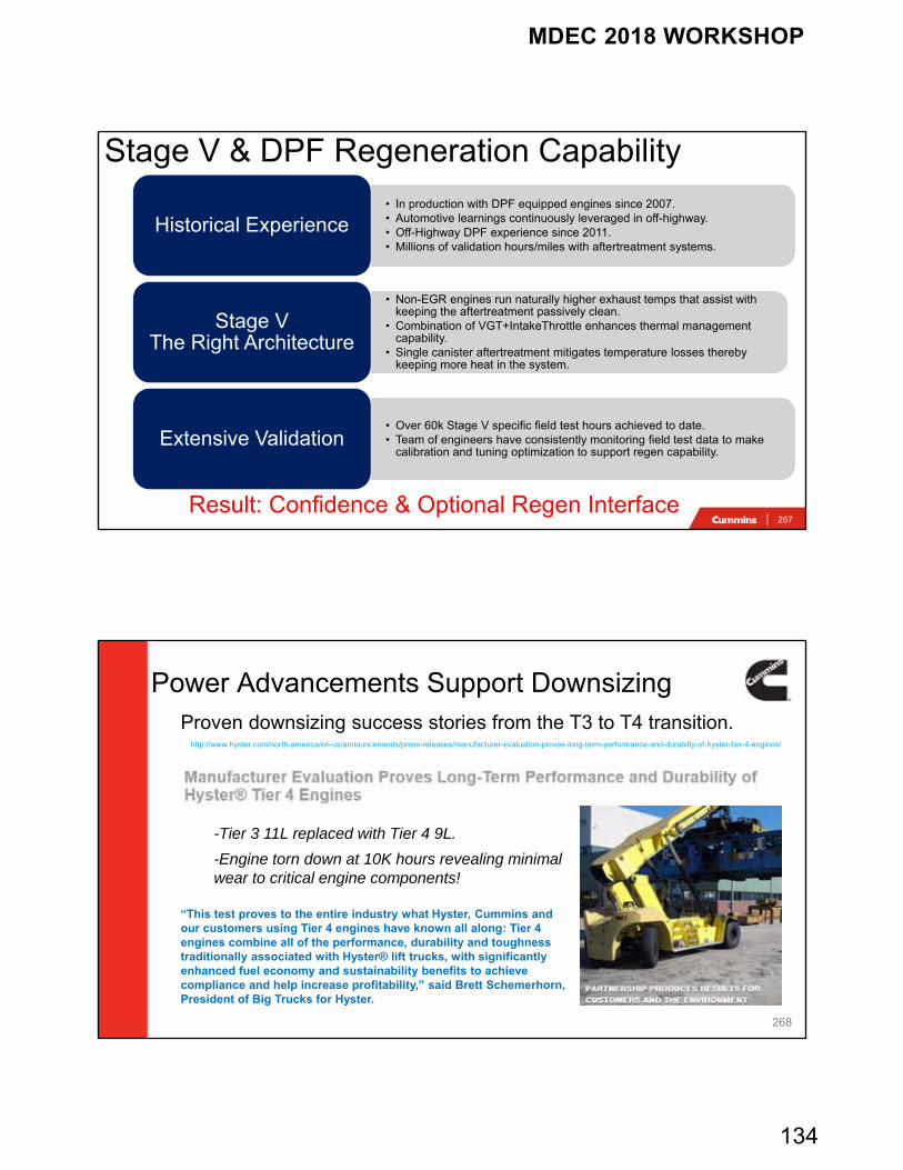
Stage V & DPF Regeneration Capability
• In production with DPF equipped engines since 2007.• Automotive learnings continuously leveraged in off-highway.• Off-Highway DPF experience since 2011.• Millions of validation hours/miles with aftertreatment systems.
Historical Experience
• Non-EGR engines run naturally higher exhaust temps that assist with keeping the aftertreatment passively clean.
• Combination of VGT+IntakeThrottle enhances thermal management capability.
• Single canister aftertreatment mitigates temperature losses thereby keeping more heat in the system.
Stage V The Right Architecture
• Over 60k Stage V specific field test hours achieved to date.• Team of engineers have consistently monitoring field test data to make
calibration and tuning optimization to support regen capability.Extensive Validation
Result: Confidence & Optional Regen Interface
268
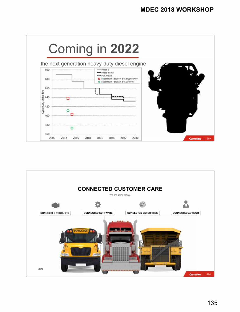
Power Advancements Support DownsizingProven downsizing success stories from the T3 to T4 transition.
http://www.hyster.com/north-america/en-us/announcements/press-releases/manufacturer-evaluation-proves-long-term-performance-and-durabilty-of-hyster-tier-4-engines/
“This test proves to the entire industry what Hyster, Cummins and our customers using Tier 4 engines have known all along: Tier 4 engines combine all of the performance, durability and toughness traditionally associated with Hyster® lift trucks, with significantly enhanced fuel economy and sustainability benefits to achieve compliance and help increase profitability,” said Brett Schemerhorn, President of Big Trucks for Hyster.
-Tier 3 11L replaced with Tier 4 9L.
-Engine torn down at 10K hours revealing minimal wear to critical engine components!
MDEC 2018 WORKSHOP
135
269
Coming in 2022the next generation heavy-duty diesel engine
270
We are going digital.
CONNECTED CUSTOMER CARE
CONNECTED ADVISORCONNECTED SOFTWARECONNECTED PRODUCTS CONNECTED ENTERPRISE
270
MDEC 2018 WORKSHOP
136
271
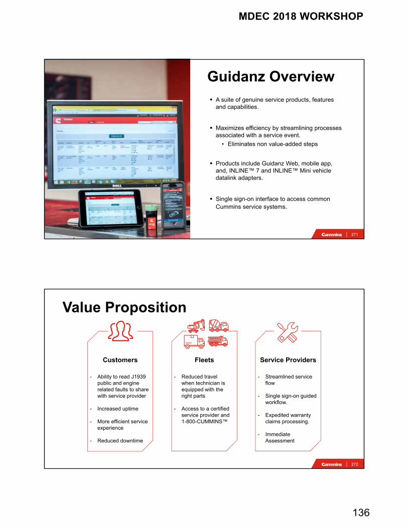
Guidanz Overview A suite of genuine service products, features
and capabilities.
Maximizes efficiency by streamlining processes associated with a service event.
• Eliminates non value-added steps
Products include Guidanz Web, mobile app, and, INLINE™ 7 and INLINE™ Mini vehicle datalink adapters.
Single sign-on interface to access common Cummins service systems.
272
Topic he
Value Proposition
Customers
- Ability to read J1939 public and engine related faults to share with service provider
- Increased uptime
- More efficient service experience
- Reduced downtime
Fleets
- Reduced travel when technician is equipped with the right parts
- Access to a certified service provider and 1-800-CUMMINS™
Service Providers
- Streamlined service flow
- Single sign-on guided workflow.
- Expedited warranty claims processing.
- Immediate Assessment
MDEC 2018 WORKSHOP
137
273
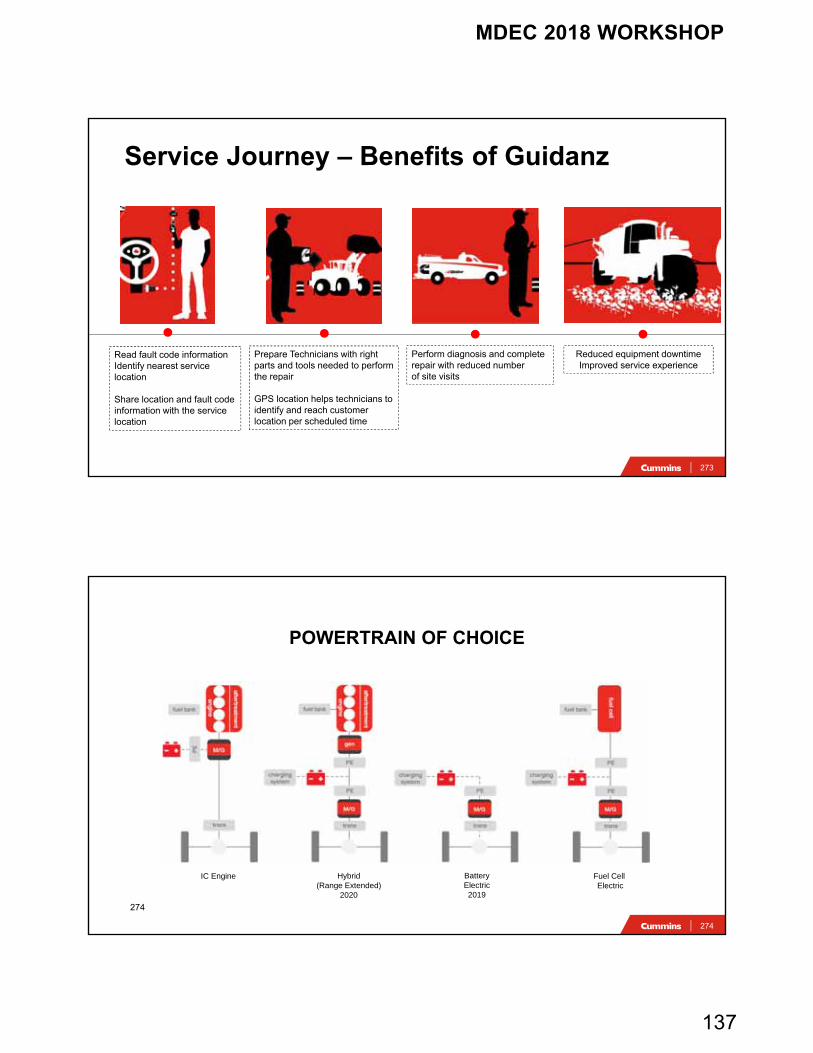
Read fault code informationIdentify nearest service location
Share location and fault code information with the service location
Prepare Technicians with right parts and tools needed to performthe repair
GPS location helps technicians to identify and reach customer location per scheduled time
Perform diagnosis and complete repair with reduced number of site visits
Reduced equipment downtimeImproved service experience
Service Journey – Benefits of Guidanz
274
POWERTRAIN OF CHOICE
BatteryElectric2019
Hybrid(Range Extended)
2020
Fuel Cell Electric
IC Engine
274
MDEC 2018 WORKSHOP
138
275
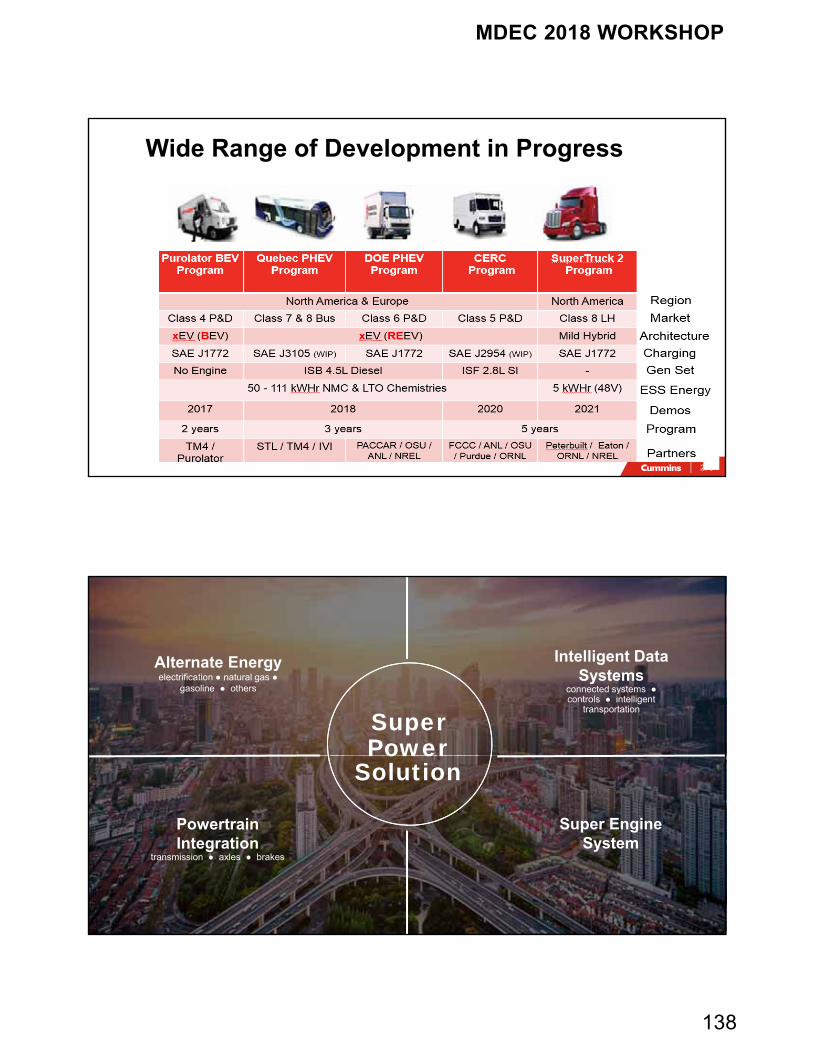
Wide Range of Development in Progress
276
Intelligent Data Systems
connected systems ●controls ● intelligent
transportation
Super EngineSystem
Alternate Energy electrification ● natural gas ●
gasoline ● others
Powertrain Integration
transmission ● axles ● brakes
SuperPower
Solution
MDEC 2018 WORKSHOP
139
277
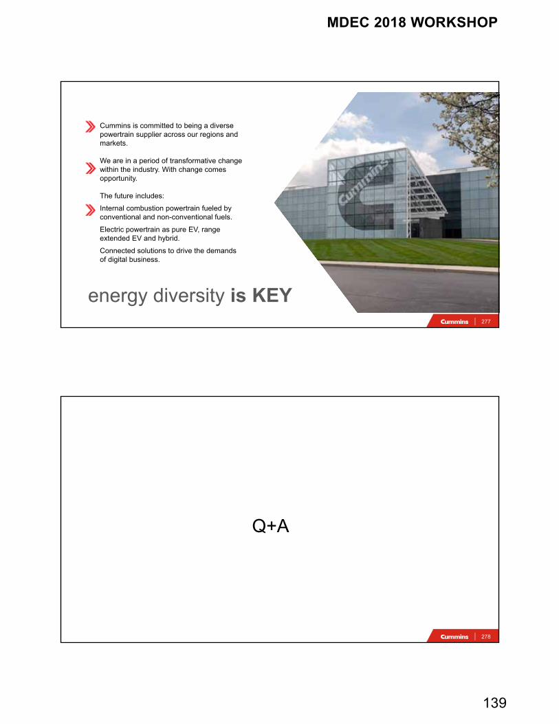
Cummins is committed to being a diverse powertrain supplier across our regions and markets.
We are in a period of transformative change within the industry. With change comes opportunity.
The future includes:
Internal combustion powertrain fueled by conventional and non-conventional fuels.
Electric powertrain as pure EV, range extended EV and hybrid.
Connected solutions to drive the demands of digital business.
energy diversity is KEY
278
Q+A
MDEC 2018 WORKSHOP
140
Sean McGinnSean McGinn
October 4th, 2018October 4th, 2018
Retrofit of DPF Technology to Mining Engines – Technical AspectsRetrofit of DPF Technology to Mining Engines – Technical Aspects
OverviewOverview
• Maintenance
• Duty Cycle Profiling
• Management – By - Numbers
• Passive DPFs
• Fully Integrated Tier 4
MDEC 2018 WORKSHOP
141
MaintenanceMaintenance
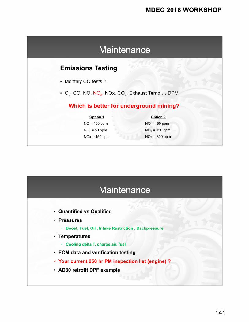
Emissions Testing
• Monthly CO tests ?
• O2, CO, NO, NO2, NOx, CO2, Exhaust Temp … DPM
Option 1
NO = 400 ppm
NO2 = 50 ppm
NOx = 450 ppm
Option 2
NO = 150 ppm
NO2 = 150 ppm
NOx = 300 ppm
Which is better for underground mining?
MaintenanceMaintenance
• Quantified vs Qualified
• Pressures
• Boost, Fuel, Oil , Intake Restriction , Backpressure
• Temperatures
• Cooling delta T, charge air, fuel
• ECM data and verification testing
• Your current 250 hr PM inspection list (engine) ?
• AD30 retrofit DPF example
MDEC 2018 WORKSHOP
142
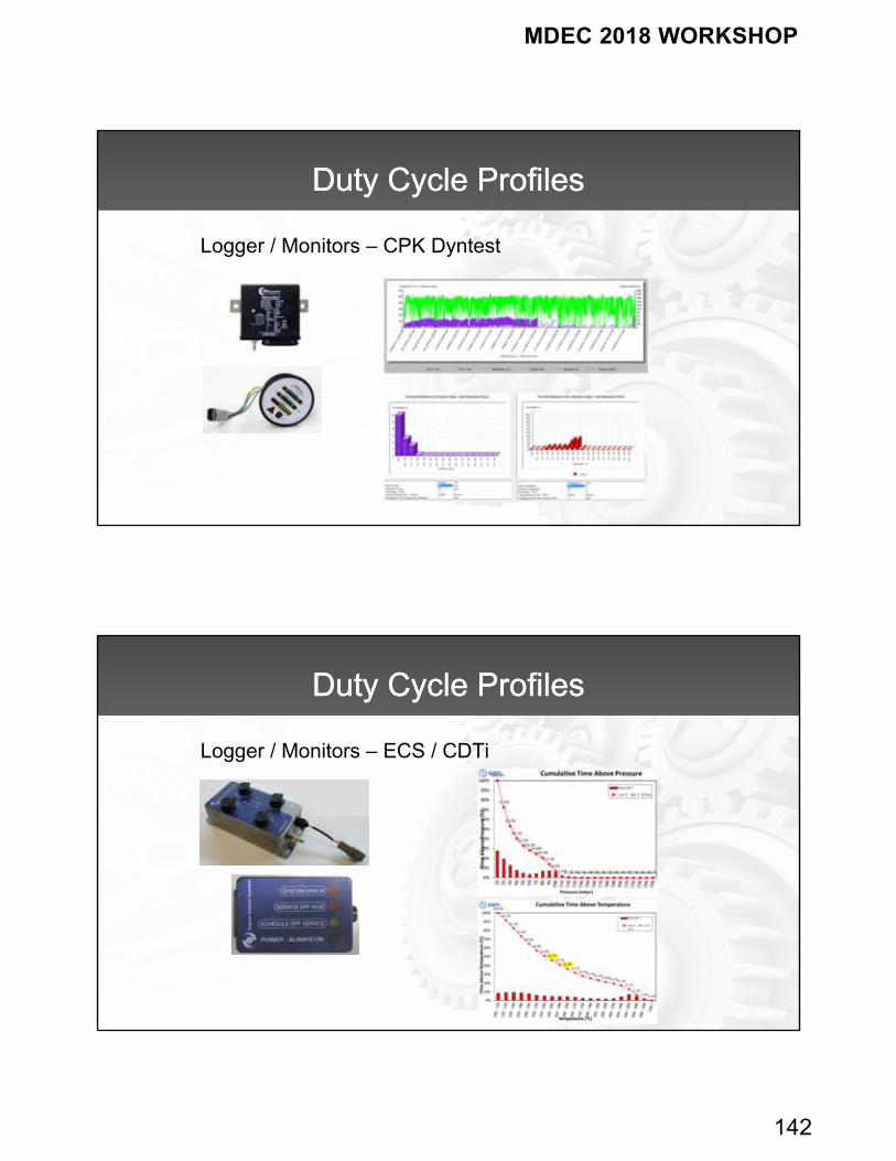
Duty Cycle ProfilesDuty Cycle Profiles
Logger / Monitors – CPK Dyntest
Duty Cycle ProfilesDuty Cycle Profiles
Logger / Monitors – ECS / CDTi
MDEC 2018 WORKSHOP
143
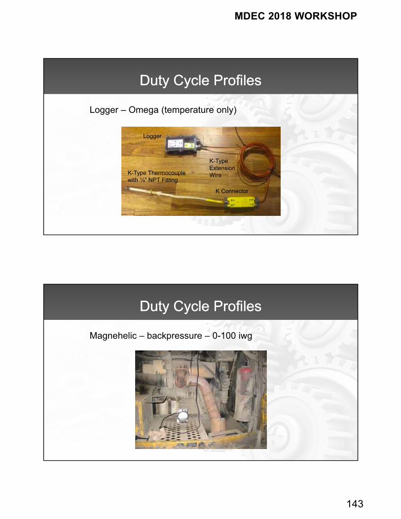
Duty Cycle ProfilesDuty Cycle Profiles
Logger – Omega (temperature only)
K-Type Thermocouplewith ¼” NPT Fitting
K Connector
K-TypeExtensionWire
Logger
Duty Cycle ProfilesDuty Cycle Profiles
Magnehelic – backpressure – 0-100 iwg
MDEC 2018 WORKSHOP
144
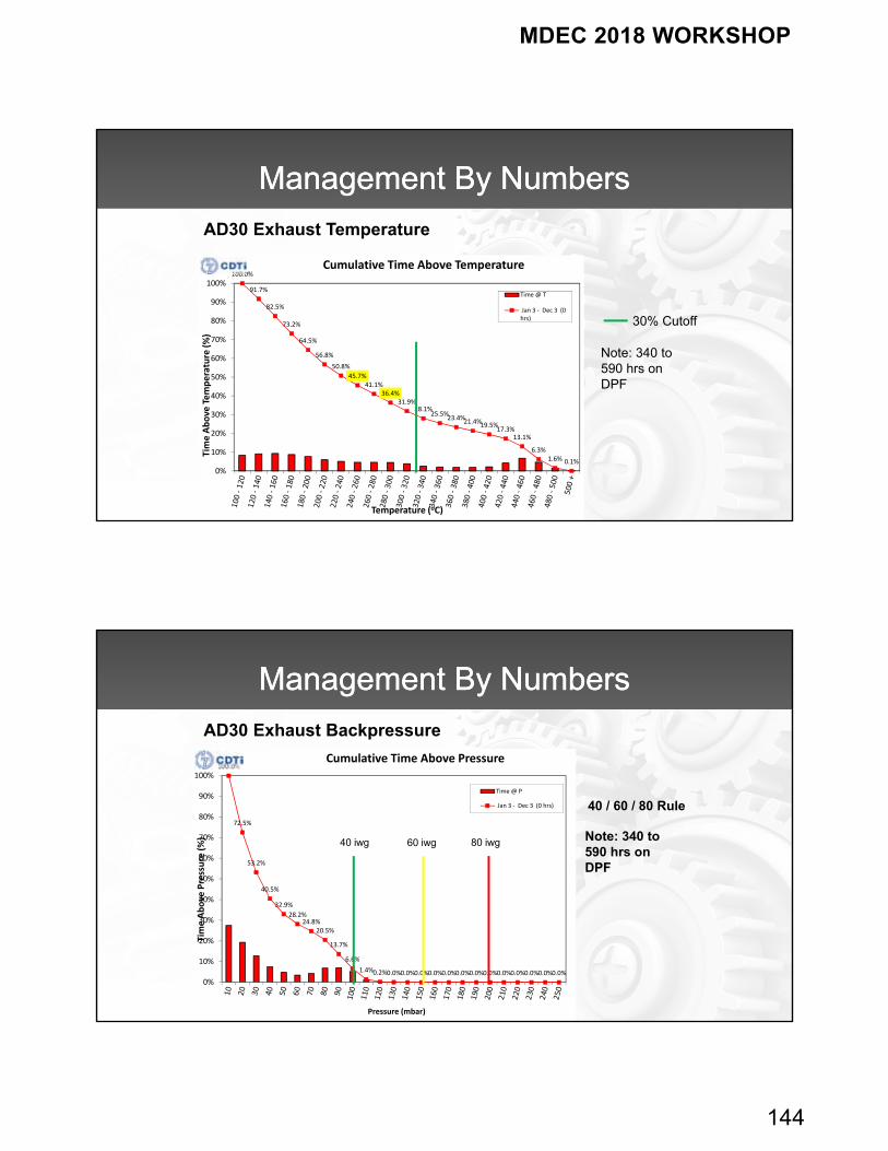
Management By NumbersManagement By Numbers
100.0%
91.7%
82.5%
73.2%
64.5%
56.8%
50.8%
45.7%41.1%
36.4%31.9%
28.1%25.5%
23.4%21.4%19.5%
17.3%13.1%
6.3%1.6% 0.1%
0%
10%
20%
30%
40%
50%
60%
70%
80%
90%
100%
Time Above Temperature (%)
Temperature (oC)
Cumulative Time Above Temperature
Time @ T
Jan 3 ‐ Dec 3 (0hrs) 30% Cutoff
Note: 340 to 590 hrs on DPF
AD30 Exhaust Temperature
Management By NumbersManagement By Numbers
AD30 Exhaust Backpressure
100.0%
72.5%
53.2%
40.5%
32.9%
28.2%24.8%
20.5%
13.7%
6.6%
1.4%0.2%0.0%0.0%0.0%0.0%0.0%0.0%0.0%0.0%0.0%0.0%0.0%0.0%0.0%
0%
10%
20%
30%
40%
50%
60%
70%
80%
90%
100%
Time Above Pressure (%)
Pressure (mbar)
Cumulative Time Above Pressure
Time @ P
Jan 3 ‐ Dec 3 (0 hrs) 40 / 60 / 80 Rule
Note: 340 to 590 hrs on DPF
40 iwg 60 iwg 80 iwg
MDEC 2018 WORKSHOP
145
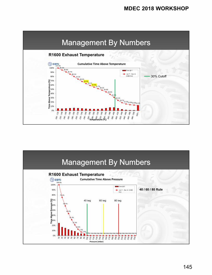
Management By NumbersManagement By Numbers
R1600 Exhaust Temperature
100.0%95.3%
90.8%
85.7%
80.1%
74.1%
68.4%63.5%
59.1%55.3%
51.7%48.2%
44.0%
38.4%
31.3%
24.1%
18.7%15.5%13.9%13.0%12.2%
0%
10%
20%
30%
40%
50%
60%
70%
80%
90%
100%
Time Above Temperature (%)
Temperature (oC)
Cumulative Time Above Temperature
Time @ T
Jan 7 ‐ Dec 11(1482 hrs) 30% Cutoff
Management By NumbersManagement By Numbers
R1600 Exhaust Temperature
100.0%
75.2%
58.5%
43.5%
31.3%
21.3%
12.6%
7.2%3.4%
0.6%0.1%0.0%0.0%0.0%0.0%0.0%0.0%0.0%0.0%0.0%0.0%0.0%0.0%0.0%0.0%
0%
10%
20%
30%
40%
50%
60%
70%
80%
90%
100%
Time Above Pressure (%)
Pressure (mbar)
Cumulative Time Above Pressure
Time @ P
Jan 7 ‐ Dec 11 (1482hrs)
40 / 60 / 80 Rule
40 iwg 60 iwg 80 iwg
MDEC 2018 WORKSHOP
146
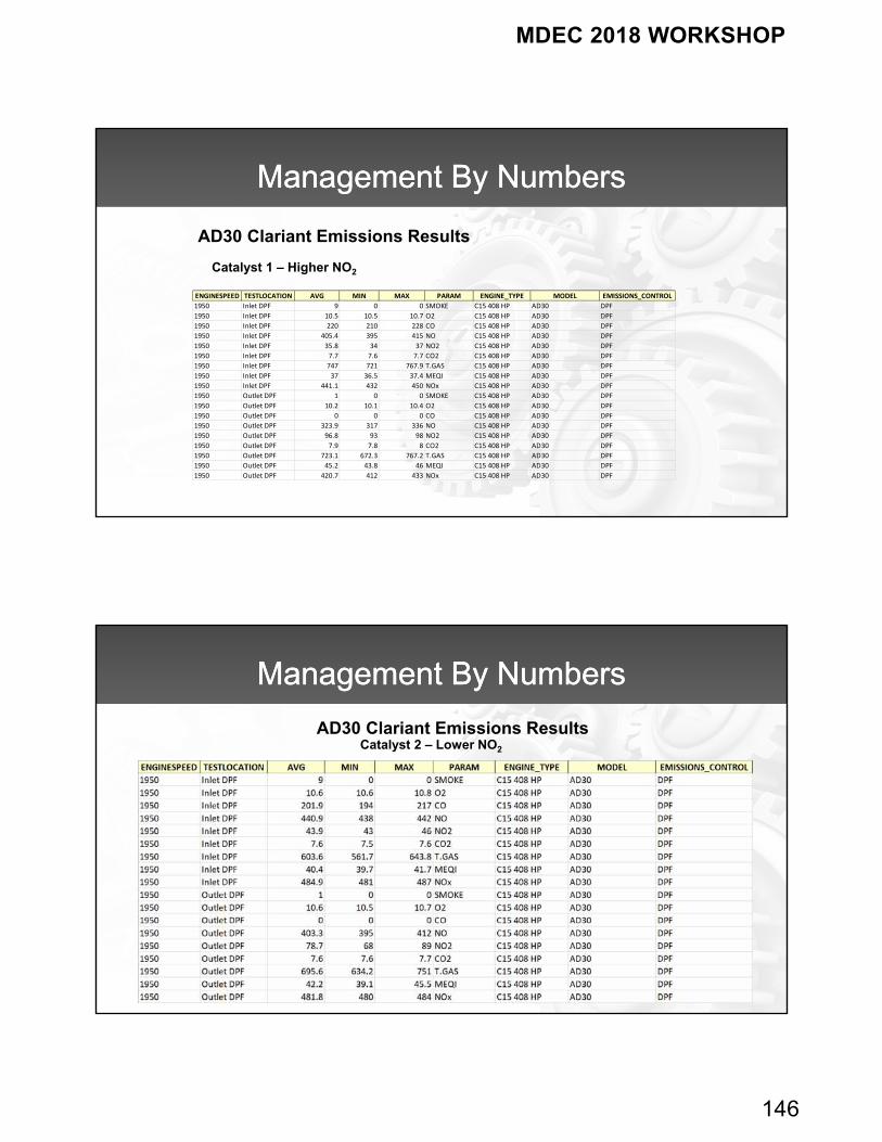
Management By NumbersManagement By Numbers
ENGINESPEED TESTLOCATION AVG MIN MAX PARAM ENGINE_TYPE MODEL EMISSIONS_CONTROL
1950 Inlet DPF 9 0 0 SMOKE C15 408 HP AD30 DPF
1950 Inlet DPF 10.5 10.5 10.7 O2 C15 408 HP AD30 DPF
1950 Inlet DPF 220 210 228 CO C15 408 HP AD30 DPF
1950 Inlet DPF 405.4 395 415 NO C15 408 HP AD30 DPF
1950 Inlet DPF 35.8 34 37 NO2 C15 408 HP AD30 DPF
1950 Inlet DPF 7.7 7.6 7.7 CO2 C15 408 HP AD30 DPF
1950 Inlet DPF 747 721 767.9 T.GAS C15 408 HP AD30 DPF
1950 Inlet DPF 37 36.5 37.4 MEQI C15 408 HP AD30 DPF
1950 Inlet DPF 441.1 432 450 NOx C15 408 HP AD30 DPF
1950 Outlet DPF 1 0 0 SMOKE C15 408 HP AD30 DPF
1950 Outlet DPF 10.2 10.1 10.4 O2 C15 408 HP AD30 DPF
1950 Outlet DPF 0 0 0 CO C15 408 HP AD30 DPF
1950 Outlet DPF 323.9 317 336 NO C15 408 HP AD30 DPF
1950 Outlet DPF 96.8 93 98 NO2 C15 408 HP AD30 DPF
1950 Outlet DPF 7.9 7.8 8 CO2 C15 408 HP AD30 DPF
1950 Outlet DPF 723.1 672.3 767.2 T.GAS C15 408 HP AD30 DPF
1950 Outlet DPF 45.2 43.8 46 MEQI C15 408 HP AD30 DPF
1950 Outlet DPF 420.7 412 433 NOx C15 408 HP AD30 DPF
Catalyst 1 – Higher NO2
AD30 Clariant Emissions Results
Management By NumbersManagement By Numbers
Catalyst 2 – Lower NO2
AD30 Clariant Emissions Results
MDEC 2018 WORKSHOP
147
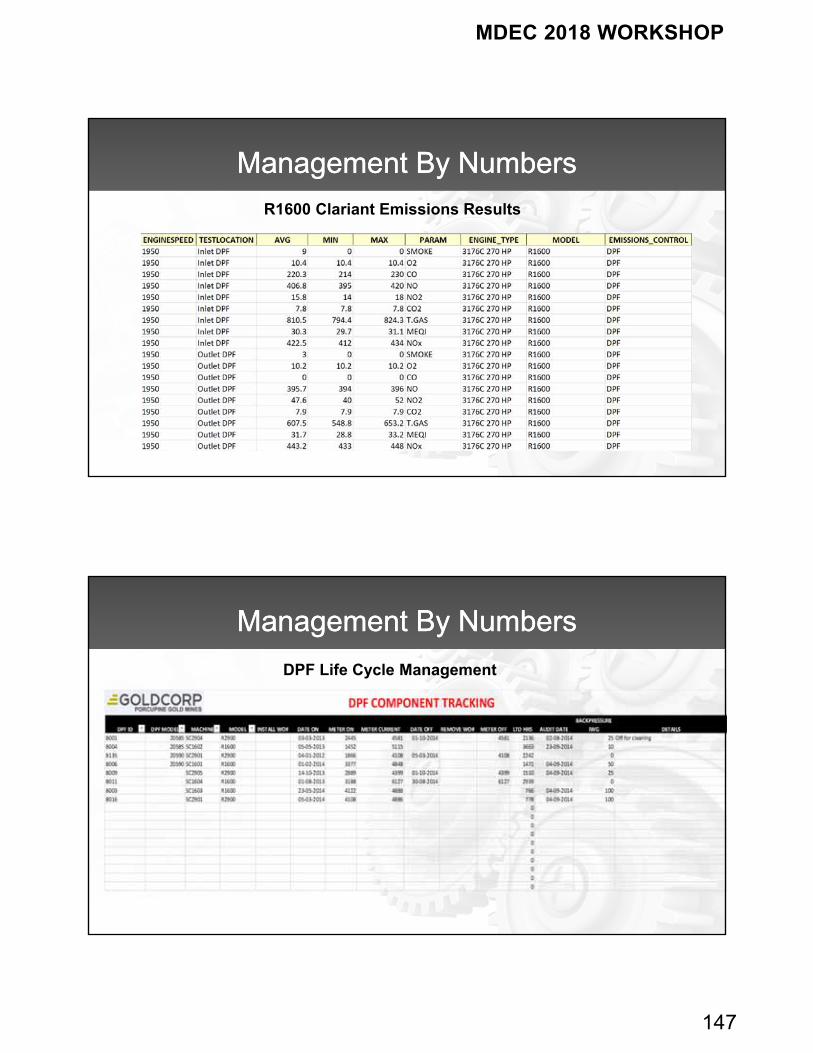
Management By NumbersManagement By Numbers
R1600 Clariant Emissions Results
Management By NumbersManagement By Numbers
DPF Life Cycle Management
MDEC 2018 WORKSHOP
148
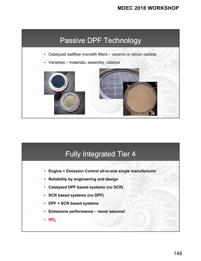
Passive DPF TechnologyPassive DPF Technology
• Catalyzed wallflow monolith filters – ceramic or silicon carbide
• Variables – materials, assembly, catalyst
Fully Integrated Tier 4Fully Integrated Tier 4
• Engine + Emission Control all-in-one single manufacturer
• Reliability by engineering and design
• Catalyzed DPF based systems (no SCR)
• SCR based systems (no DPF)
• DPF + SCR based systems
• Emissions performance – never assume!
• NO2
MDEC 2018 WORKSHOP
149
SummarySummary
• Retrofit DPFs can be a very successful solution
– DPM
– Gases
• Basic rules to being successful – follow them
• Maintenance impact – protecting investments
• Tier 4 engines – design for reliability
– Real-world performance may vary and be ready to measure
– Knowing is always better than hoping
298
MDEC 2018 WORKSHOP
150
© 2018, VERT
Experiences of VERT in DPF‐retrofitting and I&M
MEDC Diesel Workshop, Toronto – October 4th, 2018J. Czerwinski, A. Mayer, V. Hensel, Th. Lutz, VERT Association
History
VERT
Best Practice Guide
Manipulation and Tempering
Summary
Content
MDEC 2018 WORKSHOP
151
© 2018, VERT
History
MDEC 2018 WORKSHOP
152
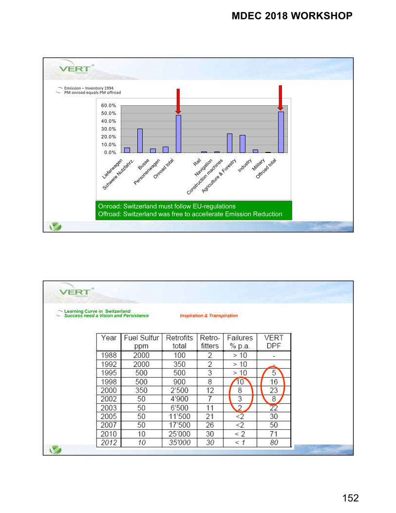
Emission – Inventory 1994PM onroad equals PM offroad
0.0%
10.0%
20.0%
30.0%
40.0%
50.0%
60.0%
Liefe
rwag
en
Schwer
e Nut
zfahr
z.
Busse
Perso
nenw
agen
Onroa
d to
tal
Rail
Naviga
tion
Constr
uctio
n m
achin
es
Agricu
lture
& F
ores
try
Indu
stry
Milit
ary
Offroa
d to
tal
Onroad: Switzerland must follow EU-regulationsOffroad: Switzerland was free to accellerate Emission Reduction
Learning Curve in SwitzerlandSuccess need a Vision and Persistance Inspiration & Transpiration
MDEC 2018 WORKSHOP
153
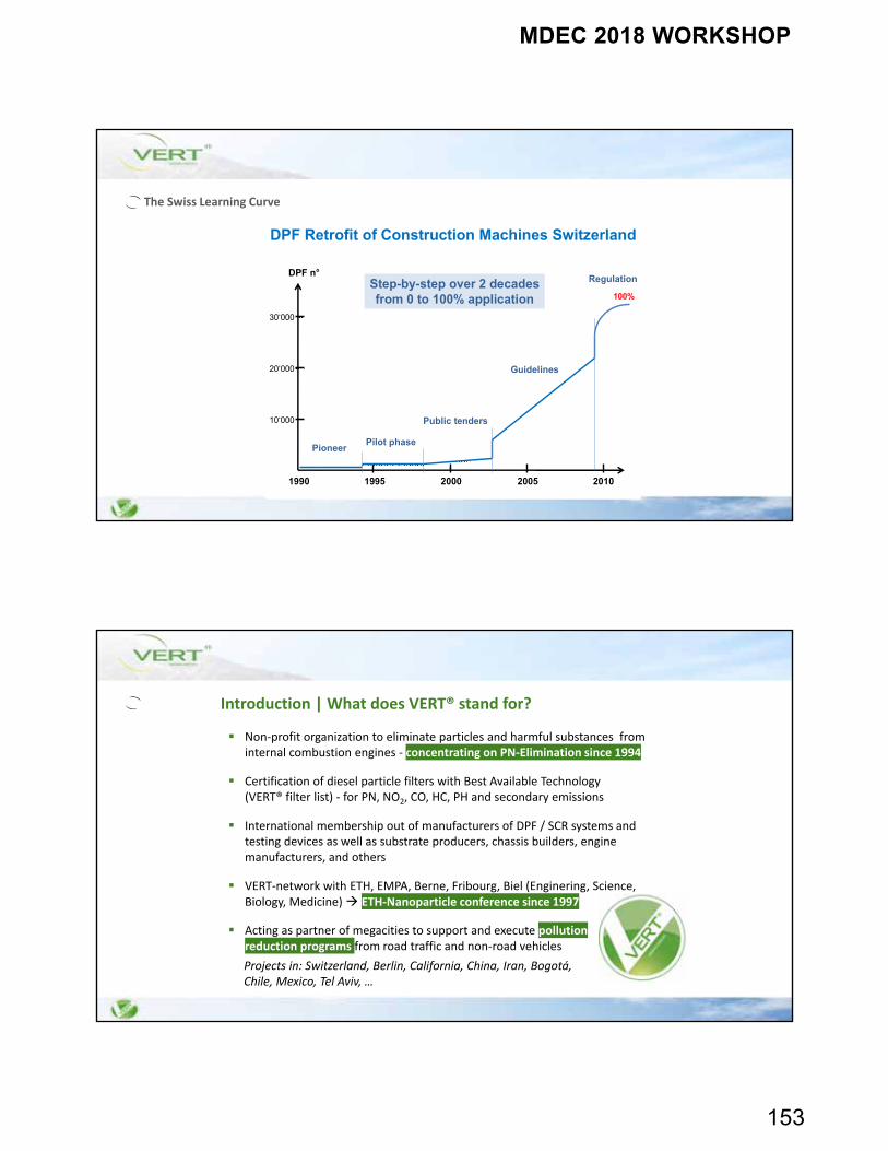
The Swiss Learning Curve
DPF Retrofit of Construction Machines Switzerland
DPF n°
1990 1995 2000 2005 2010
10‘000
30‘000
20‘000
Pioneer Pilot phase
Public tenders
Guidelines
RegulationStep-by-step over 2 decadesfrom 0 to 100% application 100%
Non‐profit organization to eliminate particles and harmful substances from internal combustion engines ‐ concentrating on PN‐Elimination since 1994
Certification of diesel particle filters with Best Available Technology(VERT® filter list) ‐ for PN, NO2, CO, HC, PH and secondary emissions
International membership out of manufacturers of DPF / SCR systems and testing devices as well as substrate producers, chassis builders, engine manufacturers, and others
VERT‐network with ETH, EMPA, Berne, Fribourg, Biel (Enginering, Science, Biology, Medicine) ETH‐Nanoparticle conference since 1997
Acting as partner of megacities to support and execute pollutionreduction programs from road traffic and non‐road vehicles
Introduction | What does VERT® stand for?
Projects in: Switzerland, Berlin, California, China, Iran, Bogotá,Chile, Mexico, Tel Aviv, …
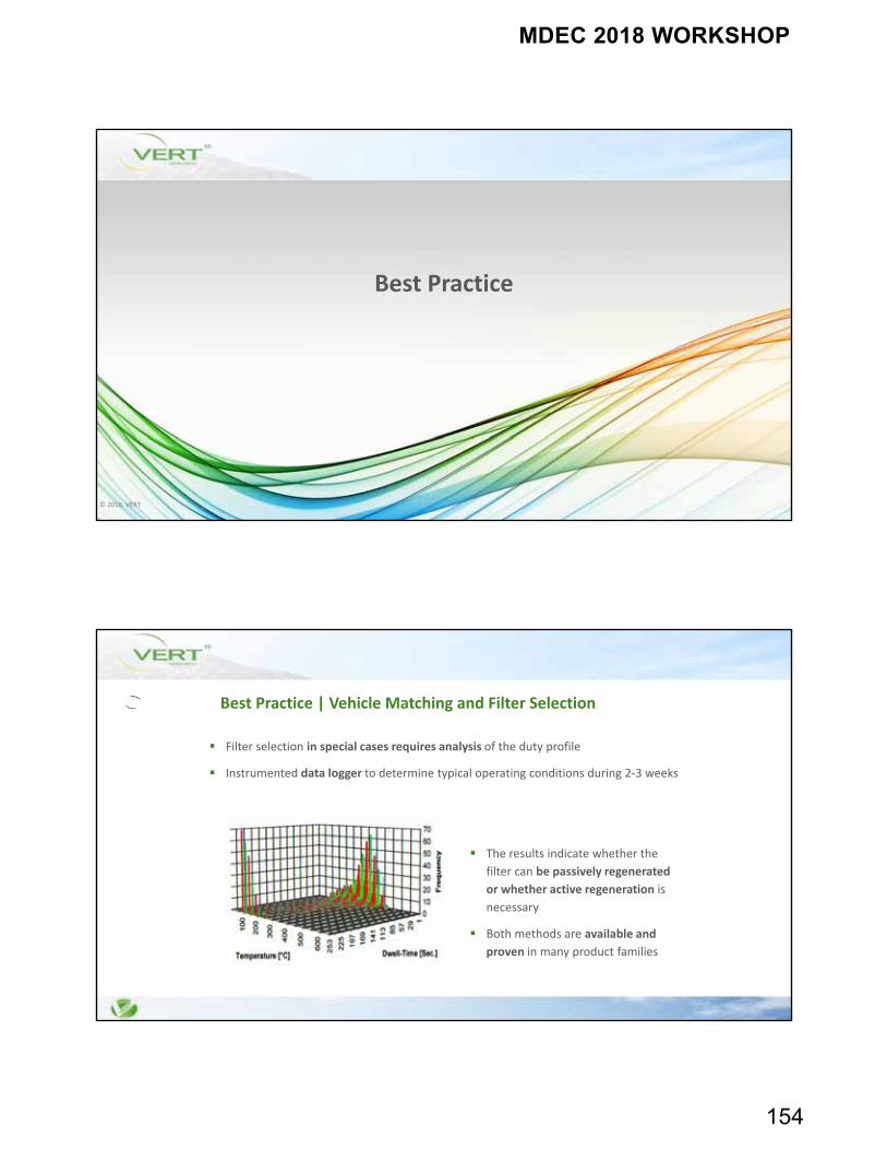
MDEC 2018 WORKSHOP
154
© 2018, VERT
Best Practice
Best Practice | Vehicle Matching and Filter Selection
Filter selection in special cases requires analysis of the duty profile
Instrumented data logger to determine typical operating conditions during 2‐3 weeks
The results indicate whether the
filter can be passively regenerated
or whether active regeneration is
necessary
Both methods are available and
proven in many product families
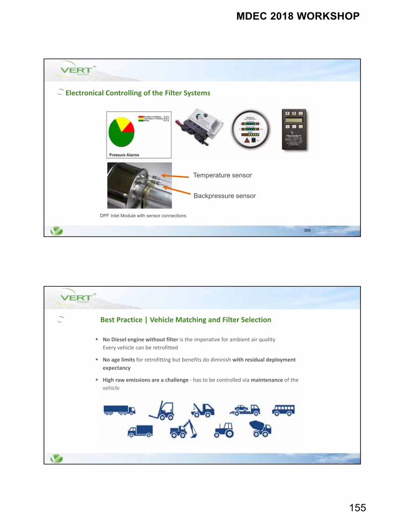
MDEC 2018 WORKSHOP
155
309
Electronical Controlling of the Filter Systems
Temperature sensor
Backpressure sensor
DPF Inlet Module with sensor connections
Best Practice | Vehicle Matching and Filter Selection
No Diesel engine without filter is the imperative for ambient air quality
Every vehicle can be retrofitted
No age limits for retrofitting but benefits do diminish with residual deployment
expectancy
High raw emissions are a challenge ‐ has to be controlled via maintenance of the
vehicle
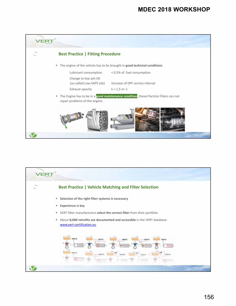
MDEC 2018 WORKSHOP
156
Best Practice | Fitting Procedure
The engine of the vehicle has to be brought in good technical conditions
Lubricant consumption < 0.5% of fuel consumption
Change to low ash Oil
(so‐called Low‐SAPS oils) increase of DPF service interval
Exhaust opacity k < 1,5 m−1
The Engine has to be in a good maintenance condition. Diesel Particle Filters can not
repair problems of the engine.
Best Practice | Vehicle Matching and Filter Selection
Selection of the right filter systems is necessary
Experience is key
VERT filter manufacturers select the correct filter from their portfolio
About 8,000 retrofits are documented and accessible in the VERT database:
www.vert‐certification.eu
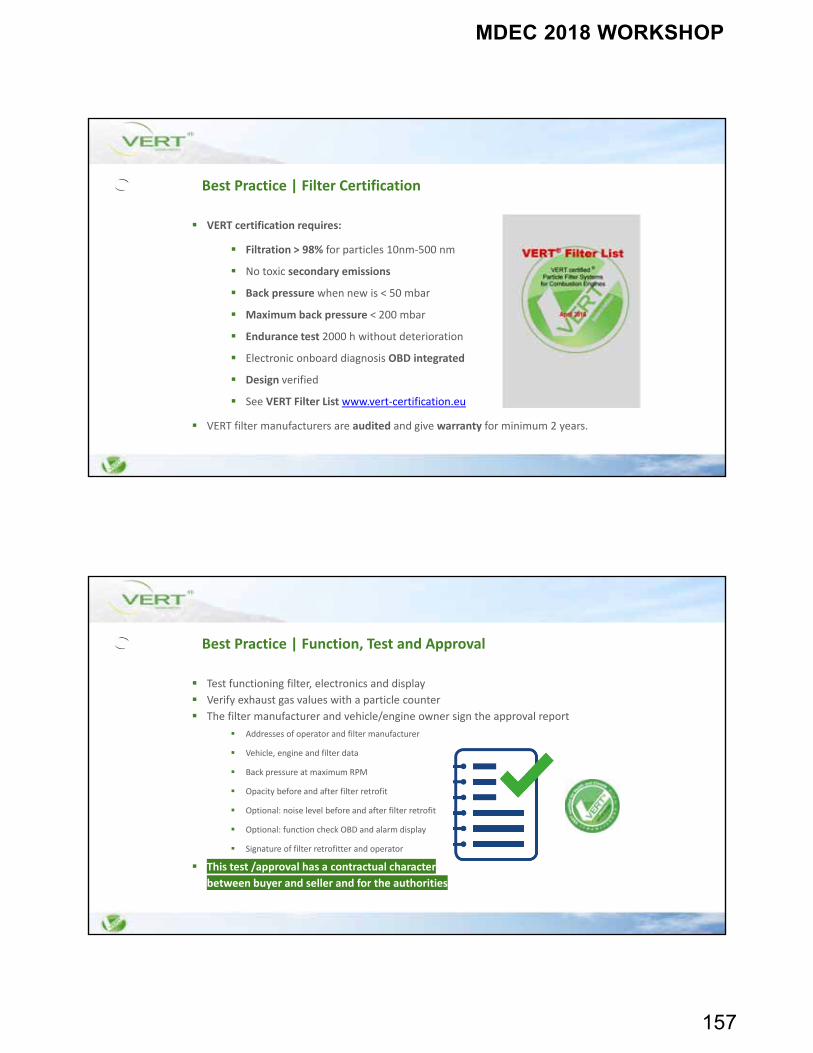
MDEC 2018 WORKSHOP
157
Best Practice | Filter Certification
VERT certification requires:
Filtration > 98% for particles 10nm‐500 nm
No toxic secondary emissions
Back pressure when new is < 50 mbar
Maximum back pressure < 200 mbar
Endurance test 2000 h without deterioration
Electronic onboard diagnosis OBD integrated
Design verified
See VERT Filter List www.vert‐certification.eu
VERT filter manufacturers are audited and give warranty for minimum 2 years.
Best Practice | Function, Test and Approval
Test functioning filter, electronics and display
Verify exhaust gas values with a particle counter
The filter manufacturer and vehicle/engine owner sign the approval report
Addresses of operator and filter manufacturer
Vehicle, engine and filter data
Back pressure at maximum RPM
Opacity before and after filter retrofit
Optional: noise level before and after filter retrofit
Optional: function check OBD and alarm display
Signature of filter retrofitter and operator
This test /approval has a contractual character
between buyer and seller and for the authorities
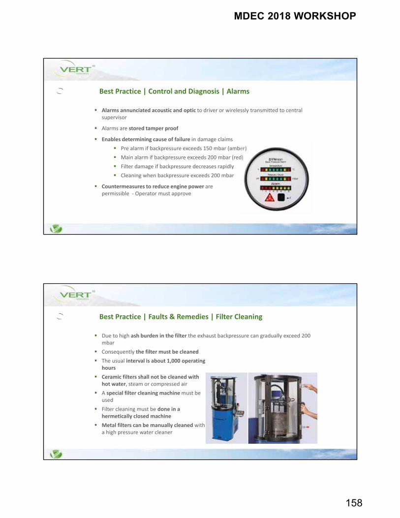
MDEC 2018 WORKSHOP
158
Best Practice | Control and Diagnosis | Alarms
Alarms annunciated acoustic and optic to driver or wirelessly transmitted to central supervisor
Alarms are stored tamper proof
Enables determining cause of failure in damage claims
Pre alarm if backpressure exceeds 150 mbar (amber)
Main alarm if backpressure exceeds 200 mbar (red)
Filter damage if backpressure decreases rapidly
Cleaning when backpressure exceeds 200 mbar
Countermeasures to reduce engine power arepermissible ‐ Operator must approve
Best Practice | Faults & Remedies | Filter Cleaning
Due to high ash burden in the filter the exhaust backpressure can gradually exceed 200 mbar
Consequently the filter must be cleaned
The usual interval is about 1,000 operatinghours
Ceramic filters shall not be cleaned withhot water, steam or compressed air
A special filter cleaning machine must beused
Filter cleaning must be done in ahermetically closed machine
Metal filters can be manually cleaned witha high pressure water cleaner
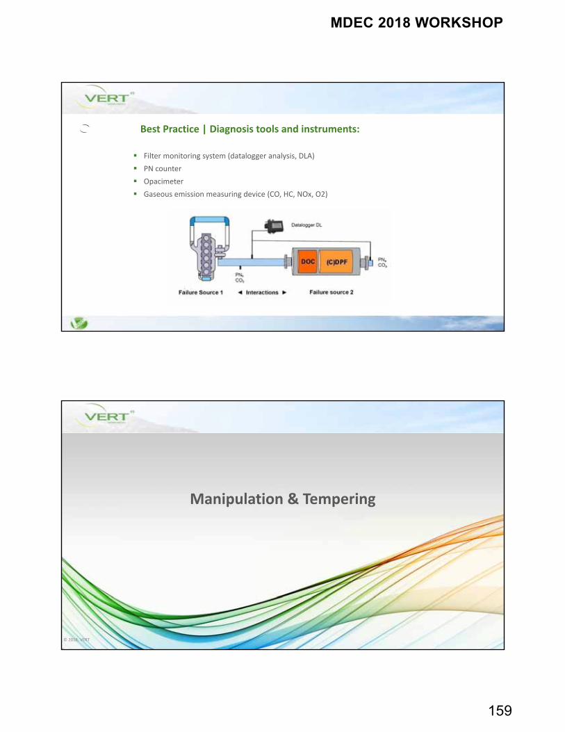
MDEC 2018 WORKSHOP
159
Best Practice | Diagnosis tools and instruments:
Filter monitoring system (datalogger analysis, DLA)
PN counter
Opacimeter
Gaseous emission measuring device (CO, HC, NOx, O2)
© 2018, VERT
Manipulation & Tempering
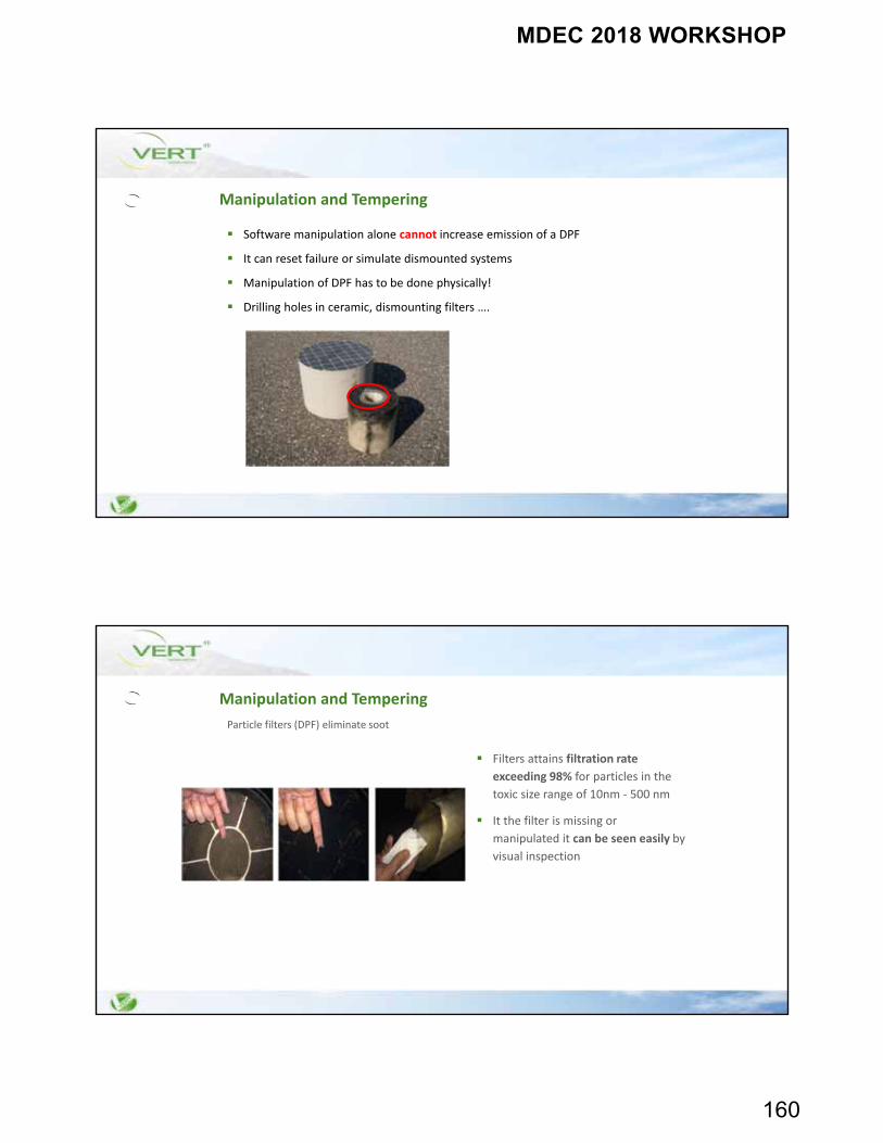
MDEC 2018 WORKSHOP
160
Software manipulation alone cannot increase emission of a DPF
It can reset failure or simulate dismounted systems
Manipulation of DPF has to be done physically!
Drilling holes in ceramic, dismounting filters ….
Manipulation and Tempering
Filters attains filtration rate
exceeding 98% for particles in the
toxic size range of 10nm ‐ 500 nm
It the filter is missing or
manipulated it can be seen easily by
visual inspection
Manipulation and Tempering
Particle filters (DPF) eliminate soot
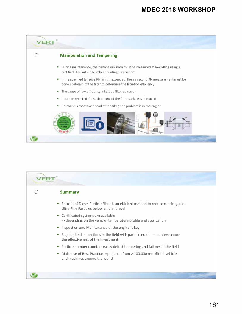
MDEC 2018 WORKSHOP
161
Manipulation and Tempering
During maintenance, the particle emission must be measured at low idling using a
certified PN (Particle Number counting) instrument
If the specified tail pipe PN limit is exceeded, then a second PN measurement must be
done upstream of the filter to determine the filtration efficiency
The cause of low efficiency might be filter damage
It can be repaired if less than 10% of the filter surface is damaged
PN count is excessive ahead of the filter, the problem is in the engine
Summary
Retrofit of Diesel Particle Filter is an efficient method to reduce cancirogenicUltra Fine Particles below ambient level
Certificated systems are available ‐> depending on the vehicle, temperature profile and application
Inspection and Maintenance of the engine is key
Regular field inspections in the field with particle number counters secure the effectiveness of the investment
Particle number counters easily detect tempering and failures in the field
Make use of Best Practice experience from > 100.000 retrofitted vehicles and machines around the world
MDEC 2018 WORKSHOP
162
Steps to be considered for DPF‐retrofitting
Matching of DPF‐System to the vehicle and to the operating profile – suitable
regeneration process
Preparations before fitting, quality & safety of DPF
Fitting procedure
Operation & maintenance (inspection)
Faults reasons actions
Control instruments & diagnostics
Organization, motivation, training and behavior
Thank your for your attention
For more information: Best Practice, Technical Inspection and Information about
projects visit
www.vert‐dpf.eu