2015/10/05 Vogtle COL Docs - AP1000 Standard Combined ... · 1 Vogtle PEmails From: Hoellman,...
31
1 Vogtle PEmails From: Hoellman, Jordan Sent: Monday, October 05, 2015 3:04 PM To: Vogtle PEmails Subject: AP1000 Standard Combined License Technical Report: Resolution of Common Q NRC Items Attachments: 2015-10-08 APP-GW-GLR-017 R1 IBR.pdf Jordan Hoellman Project Manager NRO / DNRL / LB4 U.S. Nuclear Regulatory Commission office: TWFN 6-F33 phone: (301) 415-5481 email: [email protected]
Transcript of 2015/10/05 Vogtle COL Docs - AP1000 Standard Combined ... · 1 Vogtle PEmails From: Hoellman,...
1
Vogtle PEmails
From: Hoellman, JordanSent: Monday, October 05, 2015 3:04 PMTo: Vogtle PEmailsSubject: AP1000 Standard Combined License Technical Report: Resolution of Common Q NRC
ItemsAttachments: 2015-10-08 APP-GW-GLR-017 R1 IBR.pdf
Jordan Hoellman Project Manager NRO / DNRL / LB4 U.S. Nuclear Regulatory Commission office: TWFN 6-F33 phone: (301) 415-5481 email: [email protected]
Hearing Identifier: Vogtle_COL_Docs_Public Email Number: 6 Mail Envelope Properties (29849f9094bf4caebfd0343c409fb461) Subject: AP1000 Standard Combined License Technical Report: Resolution of Common Q NRC Items Sent Date: 10/5/2015 3:04:19 PM Received Date: 10/5/2015 3:04:22 PM From: Hoellman, Jordan Created By: [email protected] Recipients: "Vogtle PEmails" <[email protected]> Tracking Status: None Post Office: HQPWMSMRS03.nrc.gov Files Size Date & Time MESSAGE 194 10/5/2015 3:04:22 PM 2015-10-08 APP-GW-GLR-017 R1 IBR.pdf 2924510 Options Priority: Standard Return Notification: No Reply Requested: No Sensitivity: Normal Expiration Date: Recipients Received:
Westinghouse Non-Proprietary Class 3
APP-GW-GLR-017 September 2015 Revision 1
AP1000 Standard Combined License Technical Report
Resolution of Common Q NRC Items
Revision 1
Westinghouse Electric Company LLC 1000 Westinghouse Drive
Cranberry Township, PA 16066
2015 Westinghouse Electric Company LLC All Rights Reserved
i
APP-GW-GLR-017 September 2015 Rev. 1
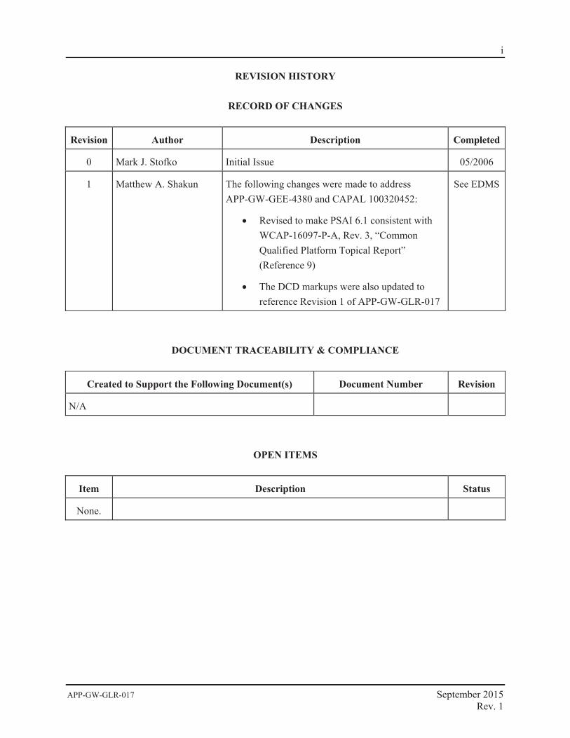
REVISION HISTORY
RECORD OF CHANGES
Revision Author Description Completed
0 Mark J. Stofko Initial Issue 05/2006
1 Matthew A. Shakun The following changes were made to address APP-GW-GEE-4380 and CAPAL 100320452:
Revised to make PSAI 6.1 consistent with WCAP-16097-P-A, Rev. 3, “Common Qualified Platform Topical Report” (Reference 9)
The DCD markups were also updated to reference Revision 1 of APP-GW-GLR-017
See EDMS
DOCUMENT TRACEABILITY & COMPLIANCE
Created to Support the Following Document(s) Document Number Revision
N/A
OPEN ITEMS
Item Description Status
None.
1
APP-GW-GLR-017 September 2015 Rev. 1
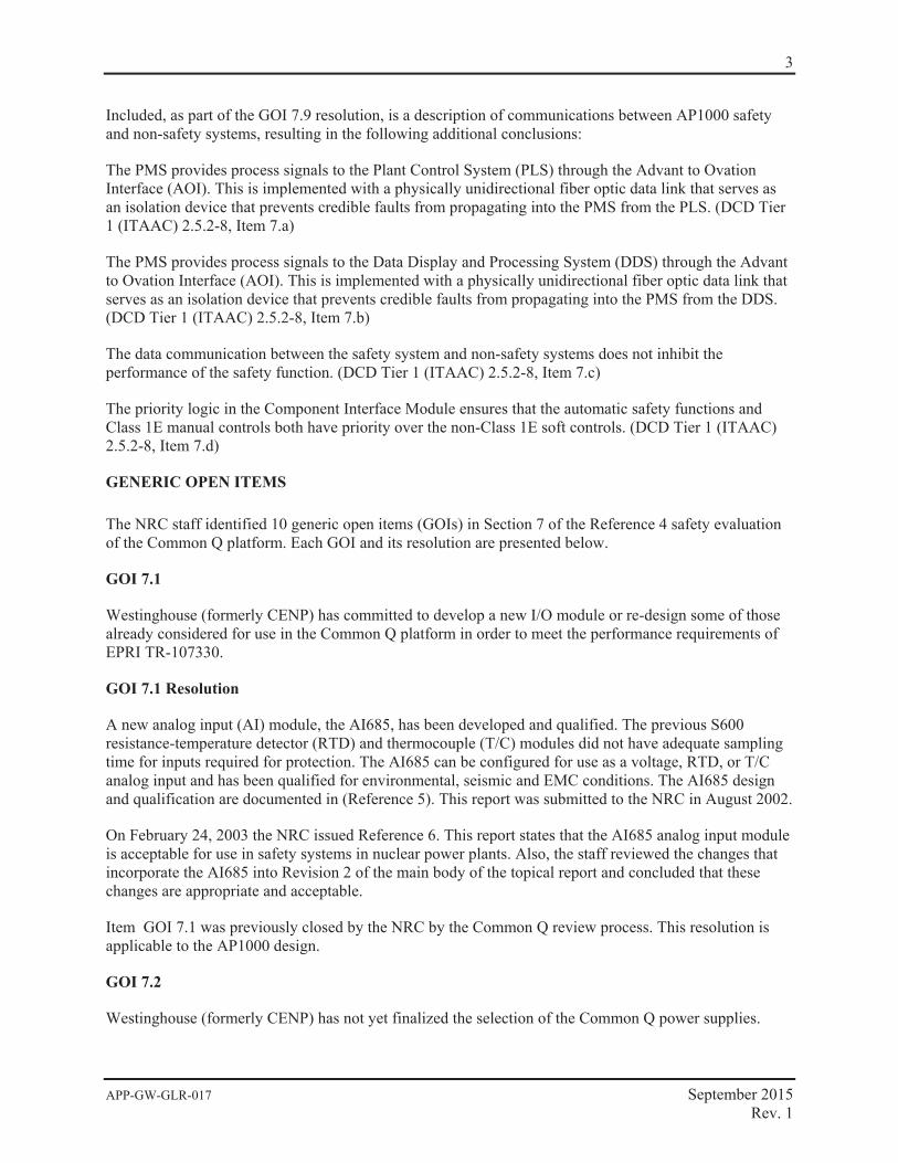
INTRODUCTION
This report summarizes the resolution of the 10 Generic Open Items (GOIs) and 14 Plant Specific Action Items (PSAIs) associated with NRC review of the Westinghouse Common Qualified (Common Q) Platform for the AP1000 plant specific design. The resolution of generic open items and plant-specific action items resulting from NRC review of the I&C platform is identified in AP1000 Design Control Document (DCD, Reference 1) Subsection 7.1.6. The resolution for generic open items and plant-specific action items is identified as COL Information Item 7.1-2 (FSER {Reference 2} Action Items 7.1.7-1 and 7.2.3-1) in DCD Subsection 7.1.6. GOI item 7.9 also provide information that was requested by ITAAC 2.5.2-8. Reference to this item will be will be made in future NRC ITAAC closure process. At this time, the ITAAC closure process is being developed by NRC and Industry.
COL Information item 7.1-2 is as follows:
Combined License applicants referencing the AP1000 certified design will provide resolution for generic open items and plant-specific action items resulting from NRC review of the I&C platform. This will include definition of a methodology for overall response time testing.
For the GOIs, resolution was provided as part of the Common Q , NRC review process. The NRC has issued an SER that generically closed all of the GOIs, with the exception of GOI item 7.8. Westinghouse will be submitting a generic Common Q report to close GOI 7.8. For GOIs, 7.1 thru 7.7, the generic resolutions that was provided to NRC and reviewed and approved ( References 4,6,7) are applicable to the AP1000 design. For items GOI 7.8, 7.9, and 7.10, additional AP1000 specific information is provided in this report to supplement to Common Q generic design. A discussion of each GOI is provided in the report. The generic information provided in the NRC review of Common Q and the additional information provided in this report provides closure of all of the GOI items for AP1000.
As part of the review process, the NRC also issued Plant Specific Action Items 6.1 thru 6.13. These action items were provided by the NRC as a check list for any utility that would be implementing a Common Q I&C system(s) up-grade. The PSAIs were written for an operating plant implementing a Common Q upgrade, therefore some of the language, may not directly be applicable to a new plant. This report provides a discussion on how each of the PSAIs either have been addressed or will be addressed for the AP1000 design. In each case where a PSAI has not been addressed in the existing design, reference to an ITAAC that will provide the requested information for the plant action item. This report provides a discussion of how each PSAI is addressed.
TECHNICAL BACKGROUND AND CONCLUSIONS
Background
By letter dated June 5, 2000, Westinghouse (formerly CE Nuclear Power) submitted Reference 3 to the NRC for review, describing the design of the Common Qualified (Common Q) platform for safety-related instrumentation and control (I&C) applications in nuclear power plants.
Reference 4 is the NRC safety evaluation (SE) report regarding the Reference 3 topical report. The SE provided the results of the NRC staff’s review of the topical report, the accompanying appendices, and other supporting documents. Based on the information provided and the review conducted, the staff concluded that the design of the Common Q platform meets the relevant NRC regulatory requirements and is acceptable for safety-related instrumentation and control (I&C) applications in nuclear power
2
APP-GW-GLR-017 September 2015 Rev. 1
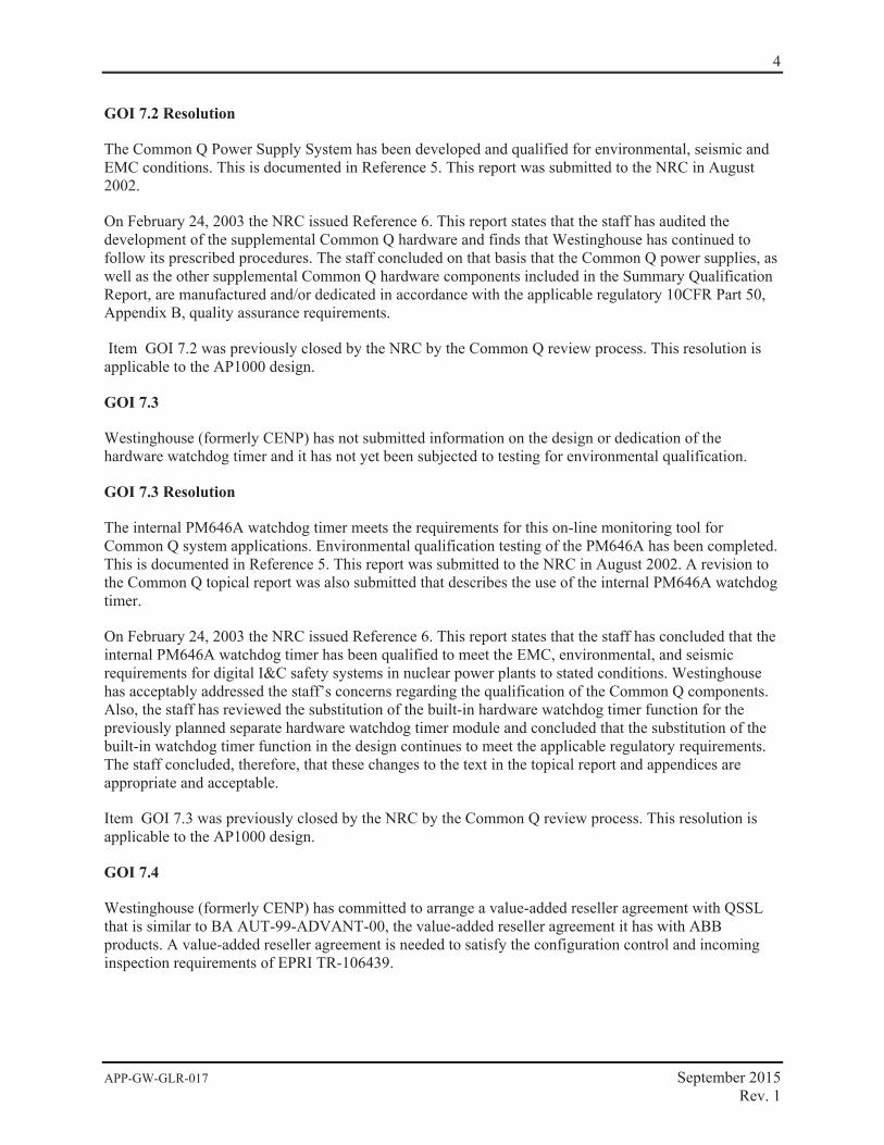
plants, subject to the satisfactory resolution of the generic open items (GOI) listed in Section 7.0 of the SE, and the plant specific action items (PSAI) listed in Section 6.0 of the SE.
The Common Q platform is a computer system consisting of a set of commercial-grade hardware and previously developed software components dedicated and qualified for use in nuclear power plants. The Common Q platform was developed by CENP from the standard AC160 computer system developed by ABB Automation Products, GmbH (ABB Products) of Europe. The Common Q platform is loaded with plant-specific application software to implement various nuclear plant safety system applications. The hardware components of the platform are:
Advant Controller 160 (AC160) with PM646A processor module
S600 input and output (S600 I/O) modules
Bus communication interface (CI631) modules
Power supply modules
Communication systems
Flat-panel display system (FPDS)
Component Interface Module (CIM)
Watchdog timer
AF100 Interface (C1631)
The AC160 software, residing on flash PROM in the processor module, consists of a real-time operating system, task scheduler, diagnostic functions, communication interfaces and plant specific application programs. The application program is created using the Asea Brown Boveri (ABB) Master Programming Language (AMPL) Configuration Control (ACC) software development environment that includes a function block library for creating specific logic for the application.
The safety-related I&C systems based on the application of Common Q platforms provide protection against unsafe reactor operation during steady state and transient power operations. They also initiate selected protective functions to mitigate the consequences of design basis events and accidents, and to safely shut down the plant by either automatic means or manual actions.
To ensure that the digital I&C systems are implemented properly, the staff considered regulatory requirements, technical positions, guides, and standards in the Standard Review Plan (SRP), (NUREG-0800) Chapter 7, Revision 4, June 1997, in the review of the Common Q platform design.
Conclusions
This report addresses the resolution of generic open items (GOI) and plant specific action items (PSAI) as requested by Combined License Information Item 7.1-2 of the AP1000 Design Control Document (DCD), Table 1.8-2. These items were identified during the NRC’s review of the Westinghouse Topical Report WCAP 16097-P-A (Common Q Platform). The GOIs and PSAIs apply to the AP1000 Protection and Safety Monitoring System (PMS) as described in this report.
3
APP-GW-GLR-017 September 2015 Rev. 1
Included, as part of the GOI 7.9 resolution, is a description of communications between AP1000 safety and non-safety systems, resulting in the following additional conclusions:
The PMS provides process signals to the Plant Control System (PLS) through the Advant to Ovation Interface (AOI). This is implemented with a physically unidirectional fiber optic data link that serves as an isolation device that prevents credible faults from propagating into the PMS from the PLS. (DCD Tier 1 (ITAAC) 2.5.2-8, Item 7.a)
The PMS provides process signals to the Data Display and Processing System (DDS) through the Advant to Ovation Interface (AOI). This is implemented with a physically unidirectional fiber optic data link that serves as an isolation device that prevents credible faults from propagating into the PMS from the DDS. (DCD Tier 1 (ITAAC) 2.5.2-8, Item 7.b)
The data communication between the safety system and non-safety systems does not inhibit the performance of the safety function. (DCD Tier 1 (ITAAC) 2.5.2-8, Item 7.c)
The priority logic in the Component Interface Module ensures that the automatic safety functions and Class 1E manual controls both have priority over the non-Class 1E soft controls. (DCD Tier 1 (ITAAC) 2.5.2-8, Item 7.d)
GENERIC OPEN ITEMS
The NRC staff identified 10 generic open items (GOIs) in Section 7 of the Reference 4 safety evaluation of the Common Q platform. Each GOI and its resolution are presented below.
GOI 7.1
Westinghouse (formerly CENP) has committed to develop a new I/O module or re-design some of those already considered for use in the Common Q platform in order to meet the performance requirements of EPRI TR-107330.
GOI 7.1 Resolution
A new analog input (AI) module, the AI685, has been developed and qualified. The previous S600 resistance-temperature detector (RTD) and thermocouple (T/C) modules did not have adequate sampling time for inputs required for protection. The AI685 can be configured for use as a voltage, RTD, or T/C analog input and has been qualified for environmental, seismic and EMC conditions. The AI685 design and qualification are documented in (Reference 5). This report was submitted to the NRC in August 2002.
On February 24, 2003 the NRC issued Reference 6. This report states that the AI685 analog input module is acceptable for use in safety systems in nuclear power plants. Also, the staff reviewed the changes that incorporate the AI685 into Revision 2 of the main body of the topical report and concluded that these changes are appropriate and acceptable.
Item GOI 7.1 was previously closed by the NRC by the Common Q review process. This resolution is applicable to the AP1000 design.
GOI 7.2
Westinghouse (formerly CENP) has not yet finalized the selection of the Common Q power supplies.
4
APP-GW-GLR-017 September 2015 Rev. 1
GOI 7.2 Resolution
The Common Q Power Supply System has been developed and qualified for environmental, seismic and EMC conditions. This is documented in Reference 5. This report was submitted to the NRC in August 2002.
On February 24, 2003 the NRC issued Reference 6. This report states that the staff has audited the development of the supplemental Common Q hardware and finds that Westinghouse has continued to follow its prescribed procedures. The staff concluded on that basis that the Common Q power supplies, as well as the other supplemental Common Q hardware components included in the Summary Qualification Report, are manufactured and/or dedicated in accordance with the applicable regulatory 10CFR Part 50, Appendix B, quality assurance requirements.
Item GOI 7.2 was previously closed by the NRC by the Common Q review process. This resolution is applicable to the AP1000 design.
GOI 7.3
Westinghouse (formerly CENP) has not submitted information on the design or dedication of the hardware watchdog timer and it has not yet been subjected to testing for environmental qualification.
GOI 7.3 Resolution
The internal PM646A watchdog timer meets the requirements for this on-line monitoring tool for Common Q system applications. Environmental qualification testing of the PM646A has been completed. This is documented in Reference 5. This report was submitted to the NRC in August 2002. A revision to the Common Q topical report was also submitted that describes the use of the internal PM646A watchdog timer.
On February 24, 2003 the NRC issued Reference 6. This report states that the staff has concluded that the internal PM646A watchdog timer has been qualified to meet the EMC, environmental, and seismic requirements for digital I&C safety systems in nuclear power plants to stated conditions. Westinghouse has acceptably addressed the staff’s concerns regarding the qualification of the Common Q components. Also, the staff has reviewed the substitution of the built-in hardware watchdog timer function for the previously planned separate hardware watchdog timer module and concluded that the substitution of the built-in watchdog timer function in the design continues to meet the applicable regulatory requirements. The staff concluded, therefore, that these changes to the text in the topical report and appendices are appropriate and acceptable.
Item GOI 7.3 was previously closed by the NRC by the Common Q review process. This resolution is applicable to the AP1000 design.
GOI 7.4
Westinghouse (formerly CENP) has committed to arrange a value-added reseller agreement with QSSL that is similar to BA AUT-99-ADVANT-00, the value-added reseller agreement it has with ABB products. A value-added reseller agreement is needed to satisfy the configuration control and incoming inspection requirements of EPRI TR-106439.
5
APP-GW-GLR-017 September 2015 Rev. 1
GOI 7.4 Resolution
On June 22, 2001 the NRC issued Reference 7. This report states that the staff has reviewed the value-added reseller agreement with QNX Software Systems Limited (QSSL), the vendor for the flat panel display system (FPDS) operating system and display system, and concludes that it satisfies the configuration control and incoming inspection guidance of EPRI TR-106439. The reseller agreement is, therefore, acceptable.
Item GOI 7.4 was previously closed by the NRC by the Common Q review process. This resolution is applicable to the AP1000 design.
GOI 7.5
Westinghouse (formerly CENP) will perform additional EMC tests and measurements on the PM646.
GOI 7.5 Resolution
The PM646 processor module has been modified to the PM646A. This modification involved the removal of an internal terminating resistor for the High-Speed Data Links (HSLs). The link termination resistor is now external to the module, permitting high-speed data link output to multiple processors using a multi-drop configuration. Additional EMC tests and measurements were performed using the PM646A. These tests are documented in Reference 5. This report was submitted to the NRC in August 2002. A revision to the Common Q topical report was also submitted that describes the modification of the PM646 to the PM646A.
On February 24, 2003 the NRC issued Reference 6. This report states that the staff concluded that the internal PM646A processor module has been qualified to meet the EMC, environmental, and seismic requirements for digital I&C safety systems in nuclear power plants to stated conditions. Westinghouse has acceptably addressed the staff’s concerns regarding the qualification of the Common Q components. Also, the staff has reviewed the change in resistor in the processor module and concurred that the resistor change is inconsequential and is, therefore, acceptable. The staff concluded that the PM646 and PM646A processor modules may be used interchangeably to suit the configuration requirements of the specific application.
Item GOI 7.5 was previously closed by the NRC by the Common Q review process. This resolution is applicable to the AP1000 design.
GOI 7.6
Westinghouse (formerly CENP) has not yet conducted seismic and environmental qualification testing on the non-AC160 hardware components. Items not yet tested include the FPDS, watchdog timer, and power supply modules.
GOI 7.6 Resolution
Seismic and environmental qualification testing on the non-AC160 hardware components has been completed. These components include the FPDS and the power supply modules. The external watchdog timer is no longer required. The internal PM646A watchdog timer meets the requirements for this on-line monitoring tool for Common Q system applications (refer to resolution of GOI 7.3 above). The seismic and environmental testing is documented in Reference 5. This report was submitted to the NRC in August
6
APP-GW-GLR-017 September 2015 Rev. 1
2002. A revision to the Common Q topical report was also submitted that describes the use of the internal PM646A watchdog timer.
On February 24, 2003 the NRC issued Reference 6. This report states that the staff has audited the development of the supplemental Common Q hardware and finds that Westinghouse has continued to follow its prescribed procedures. The staff concluded on that basis that the supplemental Common Q hardware components included in the Summary Qualification Report are manufactured and/or dedicated in accordance with the applicable regulatory 10CFR Part 50, Appendix B, quality assurance requirements. The staff concluded that Westinghouse has acceptably addressed the staff’s concerns regarding the qualification of the Common Q components, both AC160 and non-AC160.
Item GOI 7.6 was previously closed by the NRC by the Common Q review process. This resolution is applicable to the AP1000 design.
GOI 7.7
The staff has reviewed the information in the SVVP about software module testing and finds that the information provided is not sufficient for the staff to arrive at a conclusion about the adequacy of the scope of the tests for validating a software module.
GOI 7.7 Resolution
On June 22, 2001 the NRC issued Reference 7. This report states that Westinghouse submitted additional information indicating in which sections of CE-CES-195, Rev. 01, “Software Program Manual for Common Q Systems”, and topical report CENPD-396-P, Rev. 1, “Common Qualified Platform,” the staff would find the Westinghouse procedures for performing software module testing. The staff has reviewed the indicated sections and concludes that the procedures specified therein satisfy the software verification and validation program (SVVP) requirements of IEEE Std 7-4.3.2-1993 with regard to testing of software modules and are, therefore, acceptable.
Item GOI 7.7 was previously closed by the NRC by the Common Q review process. This resolution is applicable to the AP1000 design.
GOI 7.8
Westinghouse (formerly CENP) needs to provide in future submittals the design information for the loop controllers to support their diversity from the Common Q components.
GOI 7.8 Resolution
This GOI relates to the "level 3 loop controllers" referenced in the Common Q topical report integrated solution (Appendix 4). The level 3 loop controllers (LCs) provide component control based on signals from the ESFAS. Westinghouse is submitting a Common Q revision( June 2006) to address this issue.
In the AP1000 application, the CIM is used to combine signals from the PLS non-safety system soft controls and from the redundant ILCs in the PMS. Demand signals from the DAS automatic functions and the DAS manual switches bypass the CIM and interface to redundant component actuators. The CIM is configured to operate in state-based priority for the AP1000 application. This allows the preferred failure mode of the component to have the highest priority. The AP1000 application is shown in Figure 1.
7
APP-GW-GLR-017 September 2015 Rev. 1
With the generic submittal to the NRC on the CIM and the information presented above, this issue can be closed for AP1000.
GOI 7.9
The staff has reviewed the approach for the integrated solution of using the ITPs and the AF100 buses to provide separation of safety and non-safety signals and finds that there is not sufficient detail to permit an evaluation against the independence requirements set forth in IEEE Std 7-4.3.2 (Reference 8). This must be the subject of a future {Westinghouse (formerly CENP)} submittal.
GOI 7.9 Resolution
On June 22, 2001 the NRC issued a Safety Evaluation Report, Reference 7. This report states that Westinghouse has revised Appendix 4, “Common Qualified Platform Integrated Solution,” to provide additional information on the use of the interface and test processors (ITPs) and the AF100 buses to provide separation of safety and non-safety signals. The staff has reviewed the revised information in Appendix 4, Rev. 2 on the use of the ITPs and the AF100 buses to provide separation of safety and non-safety signals and finds that the conceptual approach as presented therein is consistent with the independence requirements set forth in IEEE Std 7-4.3.2. The staff, therefore, concludes that this conceptual approach may be used for guidance for the anticipated application-specific and plant-specific designs involving the integration of multiple Common Q digital instrumentation and control (l&C) upgrades. This closes GOI 7.9 as far as the conceptual approach is concerned, but the evaluation of each forthcoming design remains a plant-specific action item because the staff finds that the forthcoming details of the actual designs may require an evaluation against the independence requirements for safety systems in specific nuclear power plants.
The following plant-specific design information is provided for AP1000 communication functions to close GOI 7.9. Although conceptually the same, the AP1000 I&C system differs in some details from the integrated solution described in Appendix 4, “Common Qualified Platform Integrated Solution.” These differences, as they apply to GOI 7.9, are described below.
The AP1000 I&C system implements safety to non-safety communications and non-safety to safety communications in different ways.
Safety to Non-Safety Communication
The safety to non-safety communication is implemented with the Advant to Ovation Interface (AOI). The function of this interface is to provide dataflow from the AF100 bus of the Common Q safety system to the data highway of the Ovation non-safety system. The physical medium used is a dedicated physically unidirectional fiber optic Fast Ethernet data link. One node of the Fast Ethernet data link is the Maintenance and Test Panel (MTP) flat panel display system in the PMS. The other node of the Fast Ethernet data link is a non-safety workstation within DDS, that is a drop on the non-safety real-time data network. This arrangement is shown in Figure 2.
As mentioned above, the dedicated Fast Ethernet link used to connect the safety system to the non-safety system is fiber optic and is physically unidirectional. This arrangement provides electrical isolation between the systems and prevents all dataflow (data, protocols and handshaking) from the non-safety system to the safety system. Thus:
8
APP-GW-GLR-017 September 2015 Rev. 1
1. The PMS provides process signals to the DDS through isolation devices. The unidirectional fiber optic datalink serves as the an isolation device that prevents credible faults from propagating into the PMS from the DDS. (DCD Tier 1 (ITAAC) 2.5.2-8, Item 7.b)
2. Since the PLS utilizes the DDS network, the PMS also provides process signals to the PLS through DDS. Again, the unidirectional fiber optic datalink serves as an isolation device that prevents credible faults from propagating into the PMS from the DDS. (DCD Tier 1 (ITAAC) 2.5.2-8, Item 7.a)
3. Since the physical unidirectional nature of the connection prevents all dataflow from non-safety system to safety system, the data communication between the safety system and the non-safety systems does not inhibit the performance of the safety function. (DCD Tier 1 (ITAAC) 2.5.2-8, Item 7.c)
Non-Safety to Safety Communication
The non-safety to safety dataflow is not implemented using communication links; rather it is implemented using discrete digital signals. These signals are used to implement non-safety manual ESF system level actuations, manual blocks and resets, manual reactor trip, and manual component level controls.
The non-safety manual ESF system level actuations, manual blocks and resets, manual reactor trip originate from dedicate switches in the RSW.
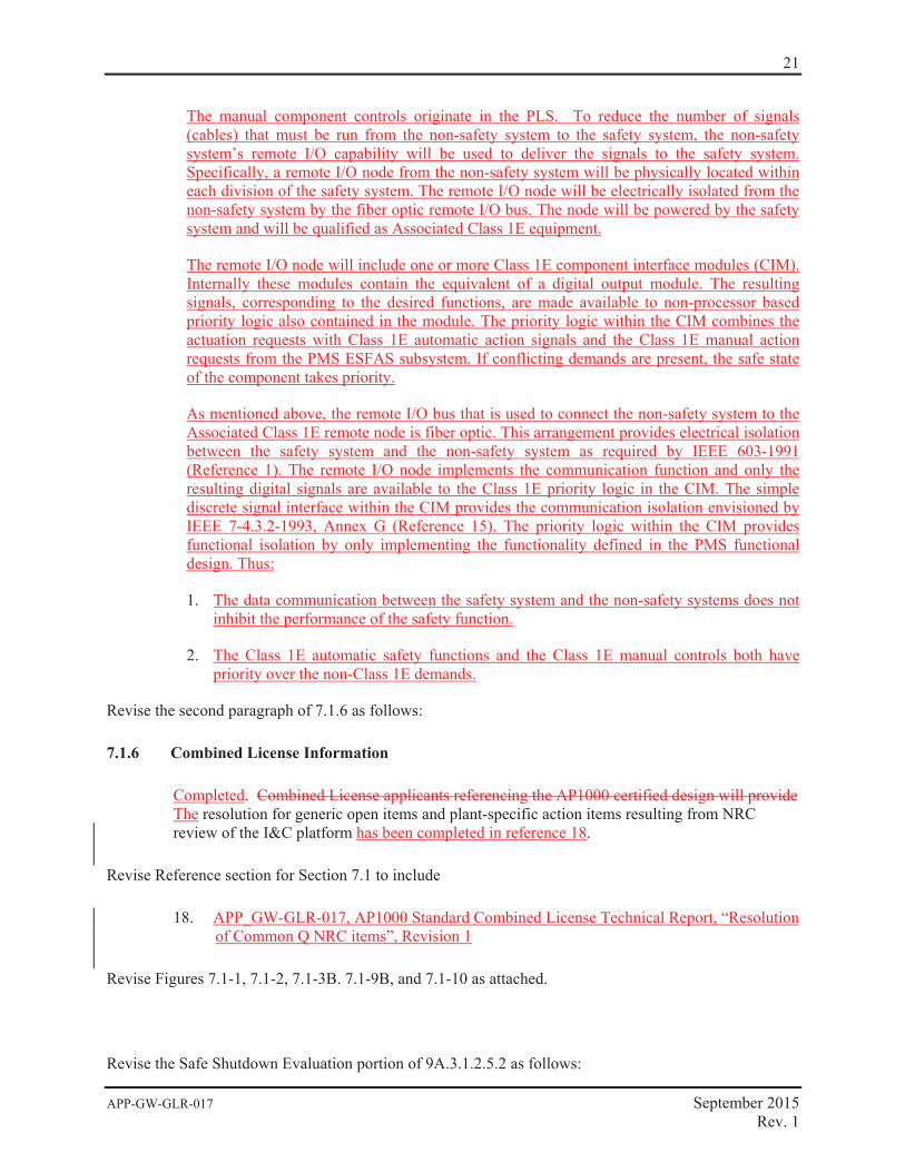
The manual component controls originate in the PLS. To reduce the number of signals (cables) that must be run from the non-safety system to the safety system, the non-safety system’s remote I/O capability will be used to deliver the signals to the safety system. Specifically, a remote I/O node from the non-safety system will be physically located within each division of the safety system. The remote I/O node will be electrically isolated from the non-safety system by the fiber optic remote I/O bus. The node controller will be powered by the safety system and will be qualified as Associated Class 1E equipment.
The remote I/O node will include one or more Class 1E component interface modules (CIM). Internally these modules contain the equivalent of a digital output module. The resulting signals, corresponding to the desired functions, are made available to non-processor based priority logic also contained in the module. The priority logic within the CIM combines the actuation requests with Class 1E automatic action signals and the Class 1E manual action requests from the PMS ESFAS subsystem. If conflicting demands are present, the safe state of the component takes priority.
As mentioned above, the remote I/O bus that is used to connect the non-safety system to the Associated Class 1E remote node controller is fiber optic. This arrangement provides electrical isolation between the safety system and the non-safety system as required by IEEE 603-1991 (Reference 1). The remote I/O node implements the communication function and only the resulting digital signals are available to the Class 1E priority logic in the CIM. The simple discrete signal interface within the CIM provides the communication isolation envisioned by IEEE 7-4.3.2-1993, Annex G (Reference 15). The priority logic within the CIM provides functional isolation by only implementing the functionality defined in the PMS functional design. Thus:
1. The data communication between the non-safety system and the safety systems does not inhibit the performance of the safety function. (DCD Tier 1 (ITAAC) 2.5.2-8, Item 7.c)
2. The Class 1E automatic safety functions and the Class 1E manual controls both have priority over the non-Class 1E demands. (DCD Tier 1 (ITAAC) 2.5.2-8, Item 7.d)
9
APP-GW-GLR-017 September 2015 Rev. 1
The generic closure of this item provided in reference 3 and the AP1000 implementation described above allows item GOI 7.9. to be closed for the AP1000 design.
GOI 7.10
The evaluation of the design for the multi-channel operator station control for the integrated solution requires detail beyond the scope of the present submittals.
GOI 7.10 Resolution
Common Q multi-channel operator stations are not used in the AP1000 design.
In AP1000, non-safety Ovation Workstations provide for component control of safety components. Non-safety control workstations are interfaced to the CIMs in PMS via Ovation Controllers. There are four Ovation Controllers, one per division. Separation between the safety and non-safety systems is provided by qualified 1E isolators. The CIMs arbitrate between inputs from the redundant ILCs and input from the non-safety Ovation Workstations. This is described in more detail in the resolution to GOI 7.8 above.
This closes GOI 7.10 for AP1000.

10
APP
-GW
-GLR
-017
Sept
embe
r 201
5
R
ev. 1
Figu
re 1
. C
ompo
nent
Log
ic S
yste
m –
AP1
000
App
licat
ion

11
APP
-GW
-GLR
-017
Sept
embe
r 201
5
R
ev. 1
Figu
re 2
. Sa
fety
to N
on-S
afet
y C
omm
unic
atio
n

12
APP-GW-GLR-017 September 2015 Rev. 1
PLANT SPECIFIC ACTION ITEMS
The NRC staff identified 14 plant specific action items (PSAIs) in Section 6 of the Reference 4 safety evaluation of the Common Q platform. Each PSAI and its resolution are presented below.
PSAI 6.1
Each licensee implementing a specific application based upon the Common Q platform must assess the suitability of the S600 I/O modules to be used in the design against its plant-specific input/output requirements.
PSAI 6.1 Resolution
The suitability of all new components is assessed to meet applicable requirements in accordance with the Quality Assurance Program. Performance requirements for these components are assured, for example, by specifying them in purchase contracts, observing vendor testing and analysis, reviewing vendor documentation, performing design reviews by the engineering department, and by performing validation tests after installation. The Quality Assurance Program is described in DCD Chapter 17 (Reference 1).
The PMS input/output categories and the S600 input/output module used to provide the interface are provided in Table 3-1 below.
Table 3-1. PMS Input/Output Signals
Item I/O Signal Type S600 I/O Module
1 Pulse input DP620
2 Current input AI688(1)
3 Voltage input AI688(1)
4 Resistance Temperature Detectors (RTD) input AI687(1)
5 Mili-volt input (thermocouple inputs) AI687(1)
6 Contact input DI621
7 Digital input DI621
8 Voltage output AO650
9 Contact output to Air Operated Valve DO620
10 Contact output to Hydraulic Operated Valve DO620
11 Contact output to Motor Operated Valve DO620
12 Contact output to Solenoid Operated Valve DO620
13 Contact output to Squib Valve DO620
14 Contact output to Circuit Breaker DO620
Note: 1. These Common Q modules are consistent with WCAP-16097-P-A, “Common Qualified Platform Topical
Report” (Reference 9).

13
APP-GW-GLR-017 September 2015 Rev. 1
The S600 input and output modules comply with EPRI –TR-107330. The electrical characteristics of the input / output modules satisfy the interface requirements of the external components.
The S600 Input/Output modules are designed to fully meet the functional and signal interface requirements for the safety system input sensors and output loads. The S600 Input/Output modules are demonstrated to be capable of performing their design function by successful completion of testing, culminating in a Factory Acceptance Test (FAT) performed by the vendor. Acceptance criteria is based on the system requirements specification.
This addresses PSAI 6.1 for AP1000.
PSAI 6.2
A hardware user interface that replicates existing plant capabilities for an application may be chosen by a licensee as an alternative to the FPDS. The review of the implementation of such a hardware user interface would be a plant-specific action item.
PSAI 6.2 Resolution
AP1000 safety systems utilize the Flat Panel Display System (FPDS) as developed by Westinghouse for Common Q safety systems. An alternative hardware interface is not used. Therefore, PSAI 6.2 is not applicable to AP1000.
This addresses PSAI 6.2 for AP1000.
PSAI 6.3
If a licensee installs a Common Q application that encompasses the implementation of FPDS, the licensee must verify that the FPDS is limited to performing display and maintenance functions only, and it is not to be used such that it is required to be operational when the Common Q system is called upon to initiate automatic safety functions. The use of the FPDS must be treated in the plant specific FMEAs.
PSAI 6.3 Resolution
On June 22, 2001, the NRC issued Reference 7. This report states that this action item has been resolved and is considered closed. Therefore, no further evaluation is required.
This addresses PSAI 6.3 for AP1000.
PSAI 6.4
Each licensee implementing a Common Q application must verify that its plant environmental data (i.e., temperature, humidity, seismic, and electromagnetic compatibility) for the location(s) in which the Common Q equipment is to be installed are enveloped by the environment considered for the Common Q qualification testing, and that the specific equipment configuration to be installed is similar to that of the Common Q equipment used for the tests.
Westinghouse configured the Common Q test specimen for seismic testing using dummy modules to fill all the used rack slots. As part of the verification of its plant-specific equipment configuration the licensee must check that it does not have any unfilled rack slots.
14
APP-GW-GLR-017 September 2015 Rev. 1
PSAI 6.4 Resolution
The Common Q safety equipment is located in the Auxiliary Building in a mild (non-harsh) environment. Therefore, age related degradation is expected to be insignificant for temperature and humidity.
The AP1000 temperature and humidity conditions for qualification of protection and safety monitoring system equipment are presented in DCD Appendix 3D (Reference 1). Temperature and humidity qualification of the protection and safety monitoring system equipment is covered by DCD Tier 1 (ITAAC) 2.5.2, Item 4 (Reference 1).
The protection and safety monitoring system seismic Category I equipment will be tested or analyzed to confirm that it can withstand seismic design basis loads without loss of safety function. The seismic qualification of the protection and safety monitoring system seismic Category I equipment is covered by DCD Tier 1 (ITAAC) 2.5.2, Item 2 (Reference 1).
The protection and safety monitoring system equipment will be tested or analyzed to confirm that it has electrical surge withstand capability (SWC), and can withstand the electromagnetic interference (EMI), radio frequency interference (RFI), and electrostatic discharge (ESD) conditions that would exist before, during and following a design basis accident without loss of safety function for the time required to perform the safety function (DCD Tier 1 (ITAAC) 2.5.2, Item 3) (Reference 1).
The as tested AP1000 PMS Architecture Diagrams will be included in testing reports covered by DCD Tier 1 ITAAC 2.5.2 (Reference 1). The Common Q hardware will include dummy modules in unused chassis slots. The dummy modules populating the unused chassis slots during seismic testing are essentially the outer cases and front faces of modules similar in size and appearance to the active modules, but lacking the internal electronics and associated hardware.
The completion of these activities shall be confirmed by the referenced ITAACs. This addresses PSAI 6.4 for AP1000.
PSAI 6.5
On the basis of its review of the Westinghouse software development process for application software, the staff concludes that the SPM specifies plans that will provide a quality software life cycle process, and that these plans commit to documentation of life cycle activities that will permit the staff or others to evaluate the quality of design features upon which the safety determination will be based. The staff will review the implementation of the life cycle process and the software life cycle process design outputs for specific applications on a plant specific basis.
PSAI 6.5 Resolution
In accordance with the Quality Assurance Program, administrative control procedures are used to establish software quality assurance and configuration management for process computer software, firmware and associated software development, computer systems, and associated documentation. They ensure that the integrity of a process software product is known and preserved throughout its life cycle from development to retirement. These controls also apply to the development tools and systems used to develop and test process software. The Quality Assurance Program is described in DCD Chapter 17 (Reference 1). The software life cycle process is covered by DCD Tier 1 (ITAAC) 2.5.2, Item 11 (Reference 1).
The completion of this activity shall be confirmed by the referenced ITAAC. This addresses PSAI 6.5 for AP1000.
15
APP-GW-GLR-017 September 2015 Rev. 1
PSAI 6.6
When implementing a Common Q safety system (i.e. PAMS, CPCS, or DPPS), the licensee must review Westinghouse’s timing analysis and validation tests for that Common Q system in order to verify that it satisfies its plant specific requirements for accuracy and response time presented in the accident analysis in Chapter 15 of the safety analysis report.
PSAI 6.6 Resolution
The accuracy and response time of the AP1000 safety systems is commensurate with the Chapter 15 Safety Analysis. The setpoint analysis and response time are covered by DCD Tier 1 (ITAAC) 2.5.2, Item 10 (Reference 1).
The completion these of activities shall be confirmed by the referenced ITAACs. This addresses PSAI 6.6 for AP1000.
PSAI 6.7
The OM and the MTP provide the human machine interface for the Common Q platform. Both the OM and MTP will include display and diagnostic capabilities unavailable in the existing analog safety systems. The Common Q design provides means for access control to software and hardware such as key switch control, control to software media, and door key locks. The human factors considerations for specific applications of the Common Q platform will be evaluated on a plant-specific basis.
PSAI 6.7 Resolution
The human factors engineering program for AP1000 is described in DCD Chapter 18 (Reference 1). PSAI 6.7 will be addressed by DCD Tier 1 (ITAAC) 3.2 (Reference 1). Completion of this item will address PSAI 6.7.
PSAI 6.8
If the licensee installs a Common Q PAMS, CPCS or DPPS, the licensee must verify on a plant-specific basis that the new system provides the same functionality as the system that is being replaced, and meets the functionality requirement applicable to those systems.
PSAI 6.8 Resolution
The AP1000 is a new plant safety system installation; therefore, PSAI 6.8 is not applicable to AP1000.
PSAI 6.9
Modifications to plant procedures and/or TS due to the installation of a Common Q safety system will be reviewed by the staff on a plant-specific basis. Each licensee installing a Common Q safety system shall submit its plant-specific request for license amendment with attendant justification.
PSAI 6.9 Resolution
The COL application will includes Technical Specification changes that are written specifically for the I&C platform implemented on the plant to address COL item 16.1-1. Plant procedures are addressed in COL item 13.5-1. Completion of these COL commitments addresses PSAI 6.9.
16
APP-GW-GLR-017 September 2015 Rev. 1
PSAI 6.10
A licensee implementing any Common Q applications (i.e., PAMS, CPCS, or DPPS) must prepare its plant specific model for the design to be implemented and perform the FMEA for that application.
PSAI 6.10 Resolution
A FMEA (APP-GW-GLR-018) has been prepared and is being transmitted separately in response to COL item 7.2-1, as discussed in the DCD Section 7.2.3.
This addresses PSAI 6.10 for the AP1000.
PSAI 6.11
If a licensee installs Common Q PAMS, CPCS, DPPS or Integrated Solution, the licensee shall demonstrate that the plant-specific Common Q application complies with the criteria for defense against common-mode failure in digital instrumentation and control system and meets the requirements of HICB BTP-19.
PSAI 6.11 Resolution
The AP1000 evaluation of Defense-in-Depth and Diversity is described in DCD Sections 7.1 and 7.7 and approved in NRC NUREG 1793 (Reference 2).
This addresses PSAI 6.11 for AP1000.
PSAI 6.12
A licensee implementing a Common Q DPPS shall define a formal methodology for overall response time testing.
PSAI 6.12 Resolution
The formal methodology for overall response time testing is based on the following:
The AP1000 Protection and Safety Monitoring System is designed to automatically initiate a protective action whenever a condition monitored by the system reaches a preset level. The protective action may consist of a reactor trip and/or an ESF actuation. In either case, the response time of the protective function shall be fast enough to limit the consequences of an event to acceptable levels, as verified by the accident analyses in DCD, Chapters 6 and 15.
A reactor trip signal acts to open the reactor trip circuit breakers, which feed power to the Control Rod Drive Mechanisms (CRDMs). The loss of power to the CRDMs causes the mechanisms to release the Rod Control Cluster Assemblies (RCCAs), which then fall by gravity into the core. There are various instrumentation delays associated with each trip function, including delays in signal generation, in opening the trip breakers, and in the release of the rods by the mechanisms.
For ESF actuation signals, the response time does not include the time required for the final actuated devices to change state (e.g., opening or closing of a valve). The accident analysis models assume time delays between the time that a process limit is reached and the necessary responsive action occurs.
17
APP-GW-GLR-017 September 2015 Rev. 1
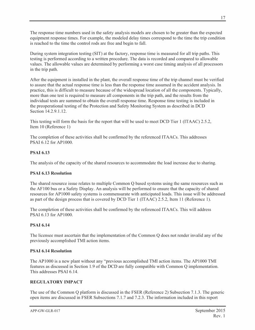
The response time numbers used in the safety analysis models are chosen to be greater than the expected equipment response times. For example, the modeled delay times correspond to the time the trip condition is reached to the time the control rods are free and begin to fall.
During system integration testing (SIT) at the factory, response time is measured for all trip paths. This testing is performed according to a written procedure. The data is recorded and compared to allowable values. The allowable values are determined by performing a worst case timing analysis of all processors in the trip path.
After the equipment is installed in the plant, the overall response time of the trip channel must be verified to assure that the actual response time is less than the response time assumed in the accident analysis. In practice, this is difficult to measure because of the widespread location of all the components. Typically, more than one test is required to measure all components in the trip path, and the results from the individual tests are summed to obtain the overall response time. Response time testing is included in the preoperational testing of the Protection and Safety Monitoring System as described in DCD Section 14.2.9.1.12.
This testing will form the basis for the report that will be used to meet DCD Tier 1 (ITAAC) 2.5.2, Item 10 (Reference 1)
The completion of these activities shall be confirmed by the referenced ITAACs. This addresses PSAI 6.12 for AP1000.
PSAI 6.13
The analysis of the capacity of the shared resources to accommodate the load increase due to sharing.
PSAI 6.13 Resolution
The shared resource issue relates to multiple Common Q based systems using the same resources such as the AF100 bus or a Safety Display. An analysis will be performed to ensure that the capacity of shared resources for AP1000 safety systems is commensurate with anticipated loads. This issue will be addressed as part of the design process that is covered by DCD Tier 1 (ITAAC) 2.5.2, Item 11 (Reference 1).
The completion of these activities shall be confirmed by the referenced ITAACs. This will address PSAI 6.13 for AP1000.
PSAI 6.14
The licensee must ascertain that the implementation of the Common Q does not render invalid any of the previously accomplished TMI action items.
PSAI 6.14 Resolution
The AP1000 is a new plant without any “previous accomplished TMI action items. The AP1000 TMI features as discussed in Section 1.9 of the DCD are fully compatible with Common Q implementation. This addresses PSAI 6.14.
REGULATORY IMPACT
The use of the Common Q platform is discussed in the FSER (Reference 2) Subsection 7.1.3. The generic open items are discussed in FSER Subsections 7.1.7 and 7.2.3. The information included in this report
18
APP-GW-GLR-017 September 2015 Rev. 1
will close open items identified in the FSER and impact those write-ups. The information presented in this report is consistent with the conclusions presented in the NRC Final Safety Evaluation Report for the AP1000.
The changes to the DCD presented in this report do not represent an adverse change to the design function of the protection system or to how design functions are performed or controlled. The changes to the DCD do not involve revising or replacing a DCD – described evaluation methodology nor involve a test or experiment not described in the DCD. The DCD change does not require a license amendment per criteria of VIII. B.5.b of Appendix D to 10 CFR Part 52.
The closure of the generic and plant specific open items and associated DCD changes do not impact features that mitigate severe accidents. The capability of the protection system to automatically and manually actuate systems and components that mitigate severe accidents is not adversely impacted. Therefore, closure of the generic and plant specific open items and associated DCD changes does not affect resolution of severe accident issues and does not require a licensing amendment based on the criteria of VIII.B.5.c of Appendix D to 10 CFR Part 52.
DCD MARKUP
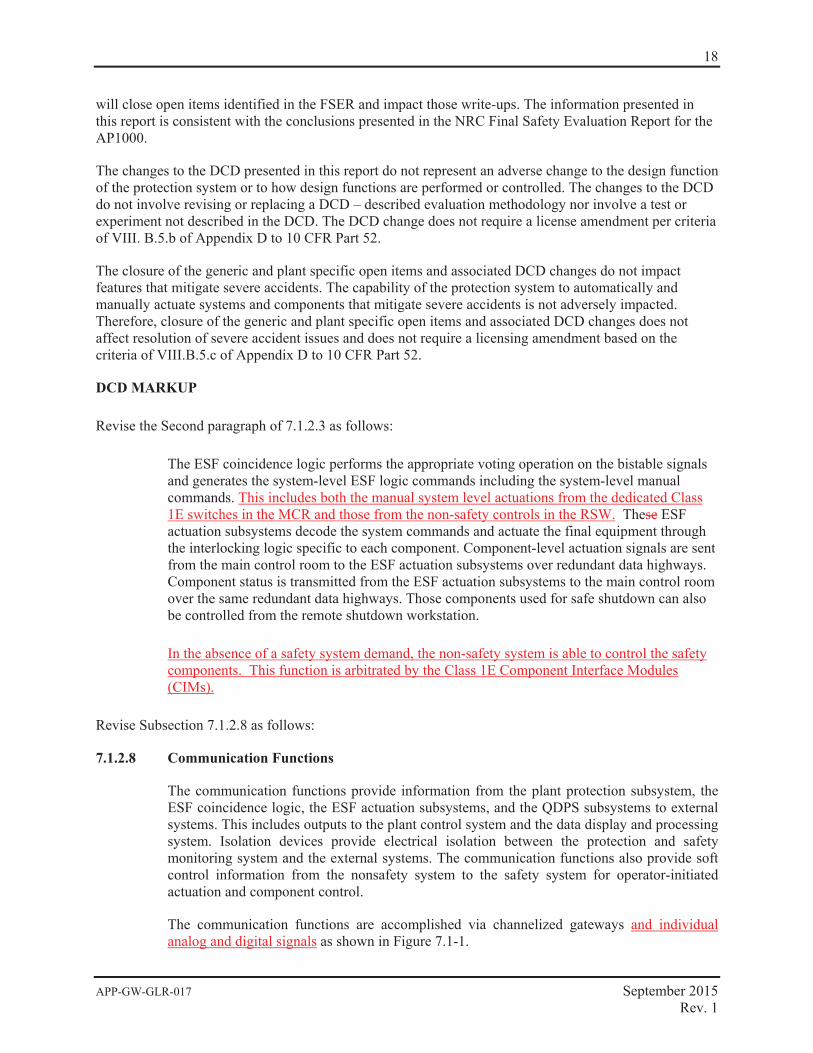
Revise the Second paragraph of 7.1.2.3 as follows:
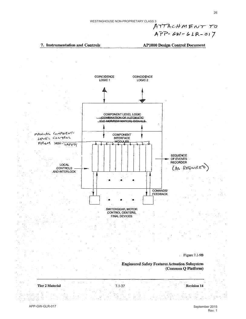
The ESF coincidence logic performs the appropriate voting operation on the bistable signals and generates the system-level ESF logic commands including the system-level manual commands. This includes both the manual system level actuations from the dedicated Class 1E switches in the MCR and those from the non-safety controls in the RSW. These ESF actuation subsystems decode the system commands and actuate the final equipment through the interlocking logic specific to each component. Component-level actuation signals are sent from the main control room to the ESF actuation subsystems over redundant data highways. Component status is transmitted from the ESF actuation subsystems to the main control room over the same redundant data highways. Those components used for safe shutdown can also be controlled from the remote shutdown workstation.
In the absence of a safety system demand, the non-safety system is able to control the safety components. This function is arbitrated by the Class 1E Component Interface Modules (CIMs).
Revise Subsection 7.1.2.8 as follows:
7.1.2.8 Communication Functions
The communication functions provide information from the plant protection subsystem, the ESF coincidence logic, the ESF actuation subsystems, and the QDPS subsystems to external systems. This includes outputs to the plant control system and the data display and processing system. Isolation devices provide electrical isolation between the protection and safety monitoring system and the external systems. The communication functions also provide soft control information from the nonsafety system to the safety system for operator-initiated actuation and component control.
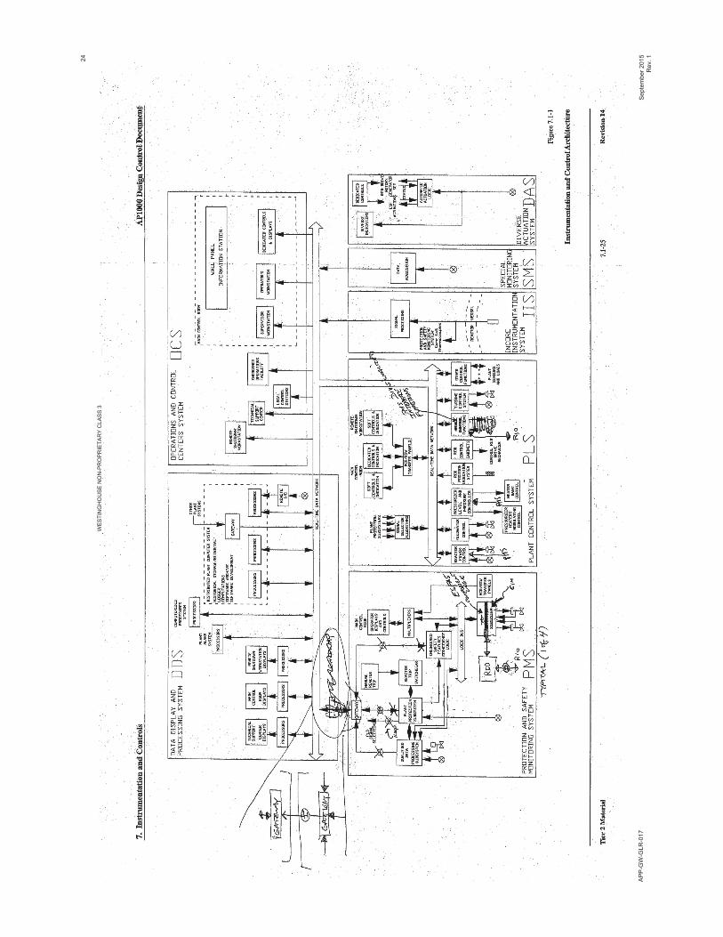
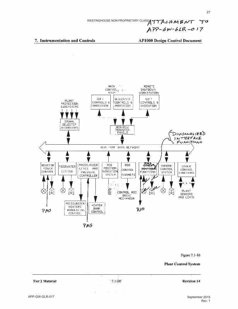
The communication functions are accomplished via channelized gateways and individual analog and digital signals as shown in Figure 7.1-1.
19
APP-GW-GLR-017 September 2015 Rev. 1
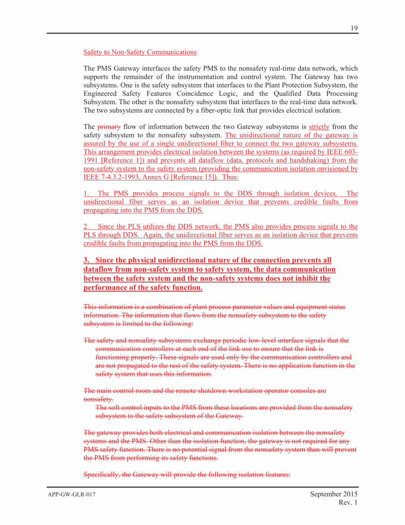
Safety to Non-Safety Communications
The PMS Gateway interfaces the safety PMS to the nonsafety real-time data network, which supports the remainder of the instrumentation and control system. The Gateway has two subsystems. One is the safety subsystem that interfaces to the Plant Protection Subsystem, the Engineered Safety Features Coincidence Logic, and the Qualified Data Processing Subsystem. The other is the nonsafety subsystem that interfaces to the real-time data network. The two subsystems are connected by a fiber-optic link that provides electrical isolation.
The primary flow of information between the two Gateway subsystems is strictly from the safety subsystem to the nonsafety subsystem. The unidirectional nature of the gateway is assured by the use of a single unidirectional fiber to connect the two gateway subsystems. This arrangement provides electrical isolation between the systems (as required by IEEE 603-1991 [Reference 1]) and prevents all dataflow (data, protocols and handshaking) from the non-safety system to the safety system (providing the communication isolation envisioned by IEEE 7-4.3.2-1993, Annex G [Reference 15]). Thus:
1. The PMS provides process signals to the DDS through isolation devices. The unidirectional fiber serves as an isolation device that prevents credible faults from propagating into the PMS from the DDS.
2. Since the PLS utilizes the DDS network, the PMS also provides process signals to the PLS through DDS. Again, the unidirectional fiber serves as an isolation device that prevents credible faults from propagating into the PMS from the DDS.
3. Since the physical unidirectional nature of the connection prevents all dataflow from non-safety system to safety system, the data communication between the safety system and the non-safety systems does not inhibit the performance of the safety function.
This information is a combination of plant process parameter values and equipment status information. The information that flows from the nonsafety subsystem to the safety subsystem is limited to the following: The safety and nonsafety subsystems exchange periodic low-level interface signals that the
communication controllers at each end of the link use to ensure that the link is functioning properly. These signals are used only by the communication controllers and are not propagated to the rest of the safety system. There is no application function in the safety system that uses this information.
The main control room and the remote shutdown workstation operator consoles are nonsafety.
The soft control inputs to the PMS from these locations are provided from the nonsafety subsystem to the safety subsystem of the Gateway.
The gateway provides both electrical and communication isolation between the nonsafety systems and the PMS. Other than the isolation function, the gateway is not required for any PMS safety function. There is no potential signal from the nonsafety system than will prevent the PMS from performing its safety functions. Specifically, the Gateway will provide the following isolation features:
20
APP-GW-GLR-017 September 2015 Rev. 1
Electrical isolation between the Class 1E and non-Class 1E ports of the Gateway, as required
by IEEE 603-1991 (Reference 1). Communication isolation between the Class 1E and non-Class 1E ports of the Gateway, as
envisioned by IEEE 7-4.3.2-1993, Annex G (Reference 15). This includes:
Class 1E communications buffering circuits to process the low-level interface signals.
Use of only simple connectionless protocols between the Class 1E and non-Class 1E ports of the Gateway. (Connectionless protocols do not use connection establishment/management/termination nor do they use acknowledgements/ negative-acknowledgements/retransmission.)
Software within the Class 1E portion of the gateway will filter the incoming message
stream and accept only valid soft control commands from a predefined list of valid commands. All other messages will be discarded.
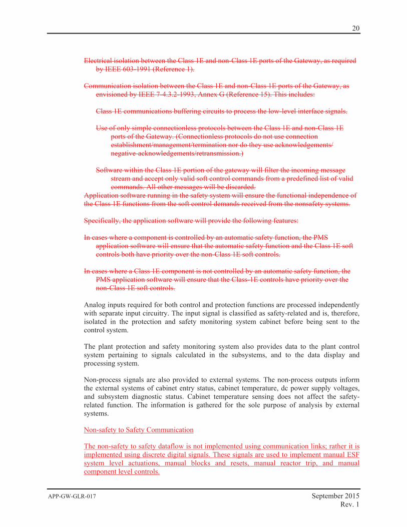
Application software running in the safety system will ensure the functional independence of the Class 1E functions from the soft control demands received from the nonsafety systems. Specifically, the application software will provide the following features: In cases where a component is controlled by an automatic safety function, the PMS
application software will ensure that the automatic safety function and the Class 1E soft controls both have priority over the non-Class 1E soft controls.
In cases where a Class 1E component is not controlled by an automatic safety function, the
PMS application software will ensure that the Class-1E controls have priority over the non-Class 1E soft controls.
Analog inputs required for both control and protection functions are processed independently with separate input circuitry. The input signal is classified as safety-related and is, therefore, isolated in the protection and safety monitoring system cabinet before being sent to the control system.
The plant protection and safety monitoring system also provides data to the plant control system pertaining to signals calculated in the subsystems, and to the data display and processing system.
Non-process signals are also provided to external systems. The non-process outputs inform the external systems of cabinet entry status, cabinet temperature, dc power supply voltages, and subsystem diagnostic status. Cabinet temperature sensing does not affect the safety-related function. The information is gathered for the sole purpose of analysis by external systems.
Non-safety to Safety Communication
The non-safety to safety dataflow is not implemented using communication links; rather it is implemented using discrete digital signals. These signals are used to implement manual ESF system level actuations, manual blocks and resets, manual reactor trip, and manual component level controls.
21
APP-GW-GLR-017 September 2015 Rev. 1
The manual component controls originate in the PLS. To reduce the number of signals (cables) that must be run from the non-safety system to the safety system, the non-safety system’s remote I/O capability will be used to deliver the signals to the safety system. Specifically, a remote I/O node from the non-safety system will be physically located within each division of the safety system. The remote I/O node will be electrically isolated from the non-safety system by the fiber optic remote I/O bus. The node will be powered by the safety system and will be qualified as Associated Class 1E equipment.
The remote I/O node will include one or more Class 1E component interface modules (CIM). Internally these modules contain the equivalent of a digital output module. The resulting signals, corresponding to the desired functions, are made available to non-processor based priority logic also contained in the module. The priority logic within the CIM combines the actuation requests with Class 1E automatic action signals and the Class 1E manual action requests from the PMS ESFAS subsystem. If conflicting demands are present, the safe state of the component takes priority.
As mentioned above, the remote I/O bus that is used to connect the non-safety system to the Associated Class 1E remote node is fiber optic. This arrangement provides electrical isolation between the safety system and the non-safety system as required by IEEE 603-1991 (Reference 1). The remote I/O node implements the communication function and only the resulting digital signals are available to the Class 1E priority logic in the CIM. The simple discrete signal interface within the CIM provides the communication isolation envisioned by IEEE 7-4.3.2-1993, Annex G (Reference 15). The priority logic within the CIM provides functional isolation by only implementing the functionality defined in the PMS functional design. Thus:
1. The data communication between the safety system and the non-safety systems does not inhibit the performance of the safety function.
2. The Class 1E automatic safety functions and the Class 1E manual controls both have priority over the non-Class 1E demands.
Revise the second paragraph of 7.1.6 as follows:
7.1.6 Combined License Information
Completed. Combined License applicants referencing the AP1000 certified design will provide The resolution for generic open items and plant-specific action items resulting from NRC review of the I&C platform has been completed in reference 18.
Revise Reference section for Section 7.1 to include
18. APP_GW-GLR-017, AP1000 Standard Combined License Technical Report, “Resolution of Common Q NRC items”, Revision 1
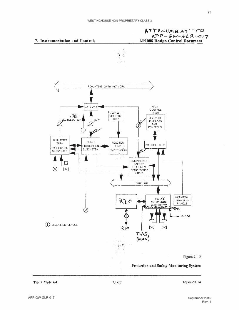
Revise Figures 7.1-1, 7.1-2, 7.1-3B. 7.1-9B, and 7.1-10 as attached.
Revise the Safe Shutdown Evaluation portion of 9A.3.1.2.5.2 as follows:
22
APP-GW-GLR-017 September 2015 Rev. 1
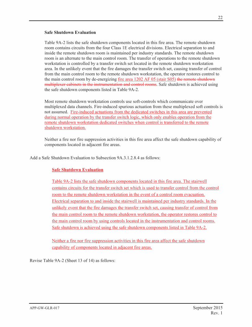
Safe Shutdown Evaluation
Table 9A-2 lists the safe shutdown components located in this fire area. The remote shutdown room contains circuits from the four Class 1E electrical divisions. Electrical separation to and inside the remote shutdown room is maintained per industry standards. The remote shutdown room is an alternate to the main control room. The transfer of operations to the remote shutdown workstation is controlled by a transfer switch set located in the remote shutdown workstation area. In the unlikely event that the fire damages the transfer switch set, causing transfer of control from the main control room to the remote shutdown workstation, the operator restores control to the main control room by de-energizing fire area 1202 AF 05 (stair S05) the remote shutdown multiplexer cabinets in the instrumentation and control rooms. Safe shutdown is achieved using the safe shutdown components listed in Table 9A-2.
Most remote shutdown workstation controls use soft-controls which communicate over multiplexed data channels. Fire-induced spurious actuation from these multiplexed soft controls is not assumed. Fire-induced actuations from the dedicated switches in this area are prevented during normal operation by the transfer switch logic, which only enables operation from the remote shutdown workstation dedicated switches when control is transferred to the remote shutdown workstation.
Neither a fire nor fire suppression activities in this fire area affect the safe shutdown capability of components located in adjacent fire areas.
Add a Safe Shutdown Evaluation to Subsection 9A.3.1.2.8.4 as follows:
Safe Shutdown Evaluation
Table 9A-2 lists the safe shutdown components located in this fire area. The stairwell contains circuits for the transfer switch set which is used to transfer control from the control room to the remote shutdown workstation in the event of a control room evacuation. Electrical separation to and inside the stairwell is maintained per industry standards. In the unlikely event that the fire damages the transfer switch set, causing transfer of control from the main control room to the remote shutdown workstation, the operator restores control to the main control room by using controls located in the instrumentation and control rooms. Safe shutdown is achieved using the safe shutdown components listed in Table 9A-2.
Neither a fire nor fire suppression activities in this fire area affect the safe shutdown capability of components located in adjacent fire areas.
Revise Table 9A-2 (Sheet 13 of 14) as follows:

23
APP-GW-GLR-017 September 2015 Rev. 1
REFERENCES 1. APP-GW-GL-700, “AP1000 Design Control Document, Revision 15.”
2. NUREG 1793, NRC “ Final Safety Evaluation Report for AP1000 Design”, September 2004
3. WCAP-16097-P-A (CENPD-396-P, Rev. 01), “Common Qualified Platform,” May 2003, including Appendices 1, 2, 3, 4 (Rev. 01) and CE-CES-195, Rev. 01, Software Program Manual for Common Q Systems.
4. NRC Safety Evaluation Report, “Acceptance for Referencing of Topical Report CENPD-396-P, Rev. 01, ‘Common Qualified Platform’ and Appendices 1, 2, 3 and 4, Rev. 01 (TAC No. MA1677),” August 11, 2000.
5. Westinghouse Report 00000-ICE-37764, Revision 02, “Summary Qualification Report of Hardware Testing for Common Q Applications,” August 2002.
6. NRC Safety Evaluation Report, “Safety Evaluation by the Office of Nuclear Reactor Regulation Related to the Westinghouse Common Q Platform Closeout of Generic Open Items and Approve Changes to Topical Report CENPD-396-P, Rev. 01, Common Qualified Platform”, February 24, 2003.
7. NRC Safety Evaluation Report, “Safety Evaluation for the Closeout of Several of the Common Qualified Platform Category 1 Open Items Related to Reports CENPD-396-P, Revision 1 and CE-CES-195, Revision 1 (TAC No. MB0780),” June 22, 2001.
8. IEEE 7-4.3.2-1993, “IEEE Standard Criteria for Digital Computers in Safety Systems of Nuclear Power Generating Stations.”
9. WCAP-16097-P-A (Proprietary), Rev. 3, “Common Qualified Platform Topical Report,” Westinghouse Electric Company LLC.
WE
STI
NG
HO
US
E N
ON
-PR
OP
RIE
TAR
Y C
LAS
S 3
24
AP
P-G
W-G
LR-0
17S
epte
mbe
r 201
5 R
ev. 1
WESTINGHOUSE NON-PROPRIETARY CLASS 3
25
APP-GW-GLR-017 September 2015 Rev. 1
WESTINGHOUSE NON-PROPRIETARY CLASS 3
26
APP-GW-GLR-017 September 2015 Rev. 1
WESTINGHOUSE NON-PROPRIETARY CLASS 3
27
APP-GW-GLR-017 September 2015 Rev. 1