2013 GOLF IRRIGATION CATALOGUE - Hunter Industries
39
GOLF ROTORS GOLF ROTORS 160
Transcript of 2013 GOLF IRRIGATION CATALOGUE - Hunter Industries

GO
LF RO
TOR
S
GOLF ROTORS
160
Table of Contents:Golf Rotors
Cross References:

GO
LF R
OTO
RS
GOLF ROTORS
161
DUAL TRAJECTORY FLEXIBILITY CONTOUR “BACK-NOZZLE” CAPABILITY
RATCHETING RISER WITH QUICKSET- 360 ADJUSTABILITY
PRIMARY NOZZLE ADAPTER
ALSO AVAILABLE, THE NEW G85B BLOCK ROTOR
THE G885 HAS POWER TO SPARE EASY ARC ADJUSTMENT WITH OR WITHOUT A TOOL
Choose from the wide assortment of efficient wind-fighting 22.5° standard trajectory nozzles, or the 15° low-angle trajectory nozzles. Either way, there is a perfect match for your unique course conditions and problem-solving needs. Regardless of the version you choose, changing nozzles is fast and easy with Hunter’s exclusive QuickChange technology.
Whether you want a little extra green behind your adjustable arc G885 rotors or a more “modeled” look to your fairway’s hard edges, contour “Back-Nozzles” are here to make your
vision a reality. They are also great for reducing water use along perimeter housing areas and other unique situations around the course. Choose from six short-range or seven mid-range nozzles to suit your needs.
Setting up your adjustable arc G885 is fast and simple. The integrated ratcheting mechanism allows a simple twist of the riser to align the right-side reversing point. Then, the adjustment ring is used to quickly set the arc and left-side reversing point. The G885 is
also easily convertible to a true non-reversing full circle rotor with our exclusive QuickSet-360 feature.
Unique irrigation problems exist on nearly every golf course. This is especially true in tight, hard-to-irrigate areas. The G885 primary nozzle adapter can solve many of these problems quickly and easily by allowing you to mix and match nozzles to get the coverage needed, or to plug the primary flow completely.
If you’re looking for a cost-effective golf rotor with a wide-range of radius and feature capabilities, including a recessed area for a yardage marker, the G85B block rotor is here. It includes all the great features of the G885 rotor at a fraction of the cost.
Boasting the highest torque output of any golf rotor on the market, the G885’s patented gear drive will push through anything that gets in its way. Try it yourself and see. With just one rotation of the turret by hand, you can clearly feel this rotor’s formidable durability. With such a powerful core, an array of efficient nozzles, and true full circle and part circle capabilities, the G885 is the golf rotor you can always count on.
With the G885, the arc is adjustable anytime; uninstalled, installed or while in operation. The convenient adjustment ring can be rotated by hand, or with the easy-to-use arc adjustment tool. This combination tool can also be used as a means to hold the riser in the popped-up position for nozzle changes.
GOLF ROTORSADVANCED FEATURESGOLF IRRIGATION
Cross References:Advanced Features Golf

GO
LF RO
TOR
S
162
TTS GOLF ROTORSADVANCED FEATURESTotal-Top-Service (TTS)
Patented Freeze Suppression
Technology
Stage 2 Filtration
Stage 1 Filtration
Access Everything Through the Top
The no-dig solution is appreciated by golfers, management, and especially the superintendent
Large and Flexible Yardage Marker Capabilities
Recessed area for placard markers; optional raised marker for popular engraved and paint-filled markers
Pilot Valve Freeze Suppression Unit
Patented FST technology prevents freeze damage— another TTS exclusive
Two-Stage Filtration in Valve Circuitry
Anti-contamination filters in pilot valve and inlet valve protect critical valve-in-head passages
Unitised Inlet Valve Assembly
Easy one-step removal of rock screen, valve seat and valve assembly
Convenient Circular Flange Design
Offset riser and compartment allows quick and easy trimming around the rotor with motorised equipment
Upper Snap Rings with Integrated Wiper Seal
Protects rotor’s riser seal from external contamination such as sand top-dressing
Through-the-Top Servicing of On-Off-Auto Selector
Simple and inexpensive to replace, should damage occur
Table of Contents:
Cross References:TTS Adv Features

GO
LF R
OTO
RS
163
ADVANCED FEATURES
Made in the USA
Through-the-Top Solenoid Connections
Keeps wire splices protected in valve-box conditions with easy solenoid servicing
Stainless Steel Seat in Pilot Valve
Durable and corrosion-free, helps prevent slow leaks and weeping in the rotor
Concealed Adjustable Pressure Regulation
Stored within the flange compartment, prevents accidental adjustments
Proudly Manufactured in the USA
Hunter is the only leading irrigation manufacturer making golf rotors in the United States of America

GO
LF RO
TOR
S
164
DIH GOLF ROTORS
Decoder-In-Head (DIH)
Made in the USA
Decoders Are Built Into Rotors
Perfect package to complement decoder control systems. All DIH rotors include two DBR/Y-6 splice connectors
State-of-the-Art Surge Suppression
Earth grounding is easily added with the Pilot SG surge protector
Individual Decoder and Solenoid Components Within Flange Compartment
Isolated configuration minimises maintenance costs year after year and into the future
Seamless No-Splice Connection Between Decoder and Solenoid
With no connectors, maintains ongoing electrical continuity and peace of mind
ADVANCED FEATURES
Table of Contents:
Cross References:DIH Adv Features

GO
LF R
OTO
RS
165
ADVANCED FEATURES
New Two-Station DIH Rotor Option
Perfect cost-effective solution for back-to-back heads around greens
Decoders Are Housed in the DIH Rotor’s Unique Flange Compartment
Improves playability and eliminates hundreds of unsightly decoder enclosures course-wide
Program Decoders from the Surface with No Disassembly
Simple, fast, and easy to program before or after installation with the wireless ICD-HP
DIH Rotors Include All the Unique Features and Benefits of TTS Rotors
When you can access everything through the top, you never have to touch the turf
Access Decoders Through the Top with No Digging Required
Servicing is easy - there's no mess with TTS DIH rotors
Built Strong in the United States of America
Among the top three irrigation manufacturers, Hunter is the only one making golf rotors in the USA
Durability, Efficiency, and Reliability Housed in the Industry’s First TTS DIH Rotor
Peace of mind from the #1 producer of gear-driven rotors in the world

GO
LF RO
TOR
S
Visit hunterindustries.com166
FEATURES• Models:
- G990 – Full circle - G995 – Adjustable arc (40°-360°)
• QuickCheck™ arc mechanism• Dual trajectory nozzle choices:
- 8 standard trajectory (22.5°) - 8 low angle trajectory (15°)
• Nozzle range: #25 to #73• Exclusive PressurePort™ nozzle
technology• Contour “Back-Nozzle” capabilities• Water lubricated gear-drive
► All TTS advanced features ► Decoder-In-Head (DIH) capable
OPERATING SPECIFICATIONS• G990
- Radius: 22.3 to 31.4 m - Flow: 6.93 to 18.92 m3/hr; 115.5 to 315.3 l/min - Pressure range: 5.5 to 8.3 bar; 550 to 830 kPa
• G995 - Radius: 20.1 to 29.6 m - Flow: 6.7 to 19.04 m3/hr; 111.7 to 317.2 l/min - Pressure range: 5.5 to 8.3 bar; 550 to 830 kPa
• All TTS rotors are pressure rated at 10 bar; 1,000 kPa
OPTIONS• C – Check-O-Matic checks up to 8 m in elevation change and readily
converts to Normally-Open Hydraulic with through the top connections• D – Decoder Valve-In-Head with all “E” specifications below*• DD – Two-station Decoder Valve-In-Head with all “E” specifications below*• E – Electric Valve-In-Head with adjustable pressure regulation, on-off-auto
selector, 210 mA (370 mA inrush) 50Hz; 190 mA (350 mA inrush) 60Hz solenoid with captive plunger and internal downstream bleed
* All DIH rotors include two IBM DBRY-6 splices for connection to the 2-wire path. See page 193 for critical recommendations on grounding DIH rotors.
► = TTS and DIH Advanced Features detailed on pages 162 and 164
G990CPop-up height: 8 cmOverall height: 34 cm Flange diameter: 19 cmFemale Inlet: 1½" ACME
G995EPop-up height: 8 cmOverall height: 34 cm Flange diameter: 19 cmFemale Inlet: 1½" ACME
G900 SERIESModels: G990 & G995Radius: 22.3 to 31.4 mFlow: 6.7 to 19.04 m3/hr; 111.7 to 317.2 l/min
G900 SERIES G800 SERIES B SERIES ROTOR ACCESSORIES RT SERIES HSJ SWING JOINTS
G990 & G995 – SPECIFICATION BUILDER: ORDER 1 + 2 + 3 + 4 + 5
1 Model 2 Valve Options 3 Nozzle 4 Regulation* 5 Options
G990 = Full Circle C = Check-O-Matic* 25 to 73 = Installed G990 Nozzle* P8 = 80 PSI (nozzles 25 to 53) S = SSU*
D = Decoder Valve-In-Head P1 = 100 PSI (nozzles 53 to 73)
DD = Two-station Decoder Valve-In-Head P2 = 120 PSI (nozzle 73)
E = Electric Valve-In-Head
G995 = Adjustable Arc 40° - 360° C = Check-O-Matic* 25 to 73 = Installed G995 Nozzle* P8 = 80 PSI (nozzles 25 to 53) S = SSU*
D = Decoder Valve-In-Head P1 = 100 PSI (nozzles 53 to 73)
DD = Two-station Decoder Valve-In-Head P2 = 120 PSI (nozzle 73)
E = Electric Valve-In-Head
* Converts to N.O. Hydraulic Valve-In-Head* SSU = #25 or #53 * SSU = P8/#25
P8/#53* Standard Stocking Unit
Example: G990 - E - 53 - P8 - S = G990 full circle electric valve-in-head, installed #53 nozzle, 80 PSI regulation, standard stocking unit model
Table of Contents:G900 Series
Cross References:

GO
LF R
OTO
RS
Visit hunterindustries.com 167GOLF IRRIGATION | Built on Innovation®
Contour “Back-Nozzle” Capabilities
Choose any nozzle from the PGP, I-40, and G70 nozzle racks, or from the short and mid-range G900 nozzles.
G900 SERIES G800 SERIES B SERIES ROTOR ACCESSORIES RT SERIES HSJ SWING JOINTS
G990 NOZZLE PERFORMANCE DATA*
Nozzle Pressure Radius** m
Flow Precip mm/hr bar kPa m3/hr l/min
255.5 550 22.3 6.93 115.2 14.0 16.26.2 620 22.9 7.36 122.6 14.1 16.3
Lt. Blue 6.9 690 23.2 7.79 129.8 14.5 16.8
7.6 760 23.8 8.29 138.2 14.7 16.98.3 830 24.1 8.72 145.4 15.0 17.4
335.5 550 23.5 8.25 137.4 15.0 17.36.2 620 23.8 8.72 145.4 15.4 17.8
Grey 6.9 690 24.4 9.22 153.7 15.5 17.9
7.6 760 24.7 9.70 161.6 15.9 18.48.3 830 25.0 10.20 170.0 16.3 18.9
385.5 550 24.4 9.22 153.7 15.5 17.96.2 620 25.0 9.75 162.4 15.6 18.0
Red 6.9 690 25.3 10.29 171.4 16.1 18.6
7.6 760 25.9 10.84 180.6 16.1 18.68.3 830 26.2 11.40 190.0 16.6 19.2
435.5 550 25.3 10.49 174.9 16.4 18.96.2 620 25.6 11.04 184.0 16.8 19.4
Dk. Brown 6.9 690 25.9 11.56 192.7 17.2 19.9
7.6 760 26.2 12.13 202.1 17.7 20.48.3 830 26.5 12.70 211.6 18.1 20.8
485.5 550 26.2 11.27 187.8 16.4 18.96.2 620 27.1 11.93 198.7 16.2 18.7
Dk. Green 6.9 690 27.4 12.45 207.4 16.5 19.1
7.6 760 27.7 13.02 216.9 16.9 19.58.3 830 28.0 13.52 225.2 17.2 19.8
535.5 550 27.1 12.31 205.2 16.7 19.36.2 620 27.4 12.88 214.6 17.1 19.8
Dk. Blue 6.9 690 28.0 13.45 224.1 17.1 19.7
7.6 760 28.3 14.02 233.6 17.4 20.18.3 830 28.7 14.58 243.0 17.8 20.5
635.5 550 28.0 14.36 23.92 18.3 21.16.2 620 28.7 14.97 249.5 18.2 21.1
Black 6.9 690 29.3 15.76 265.7 18.4 21.3
7.6 760 29.6 16.36 272.5 18.7 21.68.3 830 29.9 17.01 283.5 19.1 22.0
735.5 550 29.3 16.38 272.9 19.1 22.16.2 620 29.9 17.04 283.9 19.1 22.0
Orange 6.9 690 30.2 17.67 297.5 19.4 22.4
7.6 760 31.1 18.29 304.7 18.9 21.88.3 830 31.4 18.92 315.3 19.2 22.2
* Complies to ASAE standard. All precipitation rates calculated for 360° operation. All triangular rates are equilateral. To calculate precipitation rates for 180° operation, multiply by 2.
G900 NOZZLES
G990 & G995
G900 LOW-ANGLE NOZZLES
G990 & G995**
** Low-angle nozzles reduce radius by 15%
G995 NOZZLE PERFORMANCE DATA*
Nozzle Pressure Radius** m
Flow Precip mm/hr bar kPa m3/hr l/min
255.5 550 20.1 6.70 111.7 16.6 19.16.2 620 20.4 7.16 119.2 17.2 19.8
Lt. Blue 6.9 690 20.7 7.54 125.7 17.6 20.3
7.6 760 21.0 8.09 134.8 18.3 21.18.3 830 21.0 8.52 142.0 19.3 22.2
335.5 550 20.7 8.22 137.0 19.1 22.16.2 620 21.0 8.68 144.6 19.6 22.7
Grey 6.9 690 21.3 9.18 152.9 20.2 23.3
7.6 760 21.6 9.68 161.3 20.7 23.98.3 830 21.9 10.18 169.6 21.1 24.4
385.5 550 21.9 9.22 153.7 19.1 22.16.2 620 22.3 9.77 162.8 19.7 22.8
Red 6.9 690 22.9 10.31 171.9 19.7 22.8
7.6 760 23.2 10.81 180.2 20.1 23.38.3 830 23.5 11.36 189.3 20.6 23.8
435.5 550 22.6 10.47 174.5 20.6 23.86.2 620 22.6 11.02 183.6 21.7 25.0
Dk. Brown 6.9 690 22.9 11.52 191.9 22.0 25.4
7.6 760 23.5 12.13 202.1 22.0 25.48.3 830 23.8 12.65 210.8 22.4 25.8
485.5 550 23.5 11.40 190.0 20.7 23.96.2 620 24.1 11.95 199.1 20.6 23.8
Dk. Green 6.9 690 24.7 12.52 208.6 20.5 23.7
7.6 760 25.0 13.06 217.7 20.9 24.18.3 830 25.3 13.74 229.0 21.5 24.8
535.5 550 24.7 12.47 207.8 20.5 23.66.2 620 25.6 12.99 216.5 19.8 22.9
Dk. Blue 6.9 690 26.2 13.52 225.2 19.7 22.7
7.6 760 26.5 14.11 235.1 20.1 23.28.3 830 26.8 14.63 243.8 20.3 23.5
635.5 550 26.2 14.15 235.8 20.6 23.86.2 620 26.8 14.88 247.9 20.7 23.9
Black 6.9 690 27.4 15.67 261.2 20.8 24.0
7.6 760 27.7 16.33 272.2 21.2 24.58.3 830 28.0 16.97 282.8 21.6 24.9
735.5 550 27.1 16.51 275.2 22.4 25.96.2 620 27.7 17.13 285.4 22.3 25.7
Orange 6.9 690 28.3 17.74 295.6 22.1 25.5
7.6 760 29.0 18.38 306.2 21.9 25.38.3 830 29.6 19.04 317.2 21.8 25.1

GO
LF RO
TOR
S
Visit hunterindustries.com168
FEATURES• Model: G880 – Full circle• Nozzle choices: 7 standard trajectory (25°)• Nozzle range: #23 to #53• Exclusive PressurePort™ nozzle technology• Water lubricated gear-drive
► All TTS advanced features ► Decoder-In-Head (DIH) capable
OPERATING SPECIFICATIONS• Radius: 20.4 to 26.8 m • Flow: 5.11 to 13.15 m3/hr; 85.2 to 219.2 l/min• Pressure range: 4.5 to 6.9 bar; 450 to 690 kPa• All TTS rotors are pressure rated at 10 bar; 1,000 kPa
OPTIONS• C – Check-O-Matic checks up to 8 m in elevation change and readily
converts to Normally-Open Hydraulic with through the top connections• D – Decoder Valve-In-Head with all “E” specifications below*• DD – Two-station Decoder Valve-In-Head with all “E” specifications below*• E – Electric Valve-In-Head with adjustable pressure regulation, on-off-auto
selector, 210 mA (370 mA inrush) 50Hz; 190 mA (350 mA inrush) 60Hz solenoid with captive plunger and internal downstream bleed
* All DIH rotors include two IBM DBRY-6 splices for connection to the 2-wire path. See page 193 for critical recommendations on grounding DIH rotors.
► = TTS and DIH Advanced Features detailed on pages 162 and 164
G880CPop-up height: 8 cmOverall height: 30 cm Flange diameter: 18 cmFemale Inlet: 1½" ACME
G880EPop-up height: 8 cmOverall height: 30 cm Flange diameter: 18 cmFemale Inlet: 1½" ACME
Model: G880Radius: 20.4 to 26.8 mFlow: 5.11 to 13.15 m3/hr; 85.2 to 219.2 l/minG800 SERIES
G900 SERIES G800 SERIES B SERIES ROTOR ACCESSORIES RT SERIES HSJ SWING JOINTS
G880 – SPECIFICATION BUILDER: ORDER 1 + 2 + 3 + 4 + 5
1 Model 2 Valve Options 3 Nozzle 4 Regulation* 5 Options
G880 = Full Circle C = Check-O-Matic* 23 to 53 = Installed G880 Nozzle* P6 = 65 PSI (nozzles 23 and 25) S = SSU*
D = Decoder Valve-In-Head P8 = 80 PSI (nozzles 23 to 53)
DD = Two-station Decoder Valve-In-Head
E = Electric Valve-In-Head
* Converts to N.O. Hydraulic Valve-In-Head * SSU = #23, #25 or #48 * SSU = P6/#23, P6/#25 P8/#25, P8/#48
* Standard Stocking Unit
Example: G880 - E - 48 - P8 - S = G880 full circle electric valve-in-head, installed #48 nozzle, 80 PSI regulation, standard stocking unit model
Table of Contents:G800 Series
Cross References:

GO
LF R
OTO
RS
Visit hunterindustries.com 169GOLF IRRIGATION | Built on Innovation®
TTS EQUALS CONVENIENCE AND VERSATILITY
With TTS, every serviceable component of the rotor can be easily accessed anytime with no servicing mess.
G900 SERIES G800 SERIES B SERIES ROTOR ACCESSORIES RT SERIES HSJ SWING JOINTS
G880 NOZZLE PERFORMANCE DATA*
Nozzle Pressure Radius m
Flow Precip mm/hr Bar kPa m3/hr l/min
234.5 450 20.4 5.11 85.2 12.3 14.14.8 480 21.0 5.43 90.5 12.3 14.2
Green 5.5 550 21.6 5.91 98.4 12.6 14.6
6.2 620 21.9 6.34 105.6 13.2 15.26.9 690 22.3 6.77 112.8 13.7 15.8
254.5 450 21.6 6.54 109.0 14.0 16.14.8 480 22.3 6.79 113.2 13.7 15.8
Blue 5.5 550 22.6 7.29 121.5 14.3 16.5
6.2 620 22.9 7.79 129.8 14.9 17.26.9 690 23.2 8.18 136.3 15.2 17.6
334.5 450 22.3 7.04 117.3 14.2 16.44.8 480 22.6 7.31 121.9 14.4 16.6
Grey 5.5 550 23.2 7.88 131.4 14.7 17.0
6.2 620 23.5 8.40 140.1 15.3 17.66.9 690 23.8 8.81 146.9 15.6 18.0
384.5 450 23.2 7.97 132.9 14.9 17.24.8 480 23.5 8.25 137.4 15.0 17.3
Red 5.5 550 24.1 8.75 145.7 15.1 17.46.2 620 24.4 9.20 153.3 15.5 17.96.9 690 24.7 9.75 162.4 16.0 18.5
434.5 450 23.8 8.90 148.4 15.8 18.24.8 480 24.1 9.27 154.4 16.0 18.5
Dk. Brown 5.5 550 25.0 9.93 165.4 15.9 18.3
6.2 620 25.3 10.56 176.0 16.5 19.16.9 690 25.6 11.09 184.7 16.9 19.5
484.5 450 25.0 9.95 165.8 15.9 18.44.8 480 25.3 10.52 175.3 16.4 19.0
Dk. Green 5.5 550 25.9 11.13 185.5 16.6 19.1
6.2 620 26.2 11.79 196.5 17.2 19.86.9 690 26.5 12.36 205.9 17.6 20.3
534.5 450 25.3 10.65 177.5 16.6 19.24.8 480 25.6 11.15 185.9 17.0 19.6
Dk. Blue 5.5 550 26.5 11.95 199.1 17.0 19.6
6.2 620 26.8 12.45 207.4 17.3 20.06.9 690 26.8 13.15 219.2 18.3 21.1
* Complies to ASAE standard. All precipitation rates calculated for 360˚ operation. All triangular rates are equilateral.
G880 NOZZLES

GO
LF RO
TOR
S
Visit hunterindustries.com170
FEATURES• Model: G884 – Full circle• Dual trajectory colour-coded nozzles:
- 10 standard trajectory (22.5°) - 9 low-angle trajectory (15°)
• Nozzle range: #15 to #53• Exclusive PressurePort™ nozzle technology• Stainless steel riser• Water lubricated gear-drive
► All TTS advanced features ► Decoder-In-Head (DIH) capable
OPERATING SPECIFICATIONS• Radius: 14.9 to 28.3 m• Flow: 3.28 to 13.24 m3/hr; 54.6 to 220.6 l/min• Pressure range: 3.4 to 6.9 bar; 340 to 690 kPa• All TTS rotors are pressure rated at 10 bar; 1000 kPa
OPTIONS• C – Check-O-Matic checks up to 8 m in elevation change and readily
converts to Normally-Open Hydraulic with through the top connections• D – Decoder Valve-In-Head with all “E” specifications below*• DD – Two-station Decoder Valve-In-Head with all “E” specifications below*• E – Electric Valve-In-Head with adjustable pressure regulation, on-off-auto
selector, 210 mA (370 mA inrush) 50Hz; 190 mA (350 mA inrush) 60Hz solenoid with captive plunger and internal downstream bleed
* All DIH rotors include two IBM DBRY-6 splices for connection to the 2-wire path. See page 193 for critical recommendations on grounding DIH rotors.
► = TTS and DIH Advanced Features detailed on pages 162 and 164
Model: G884Radius: 14.9 to 28.3 mFlow: 3.28 to 13.24 m3/hr; 54.6 to 220.6 l/minG800 SERIES
G884CPop-up height: 9.5 cmOverall height: 30 cm Flange diameter: 18 cmFemale Inlet: 1½" ACME
G884EPop-up height: 9.5 cmOverall height: 30 cm Flange diameter: 18 cmFemale Inlet: 1½" ACME
G900 SERIES G800 SERIES B SERIES ROTOR ACCESSORIES RT SERIES HSJ SWING JOINTS
G884 – SPECIFICATION BUILDER: ORDER 1 + 2 + 3 + 4 + 5
1 Model 2 Valve Options 3 Nozzle 4 Regulation* 5 Options
G884 = Full Circle
(convertible to forward- facing adjustable arc rotor)
C = Check-O-Matic* 15 to 53 = Installed G880 Nozzle* P5 = 50 PSI (nozzles 15 to 18) S = SSU*
D = Decoder Valve-In-Head P6 = 65 PSI (nozzles 18 to 25)
DD = Two-station Decoder Valve-In-Head P8 = 80 PSI (nozzles 25 to 35)
E = Electric Valve-In-Head
* Converts to N.O. Hydraulic Valve-In-Head * SSU = #18, #23, #25 or #48 * SSU = P5/#18, P6/#23 P8/#25, P8/#48
* Standard Stocking Unit
Example: G884 - E - 48 - P8 - S = G884 full circle electric valve-in-head, installed #48 nozzle, 80 PSI regulation, standard stocking unit model

GO
LF R
OTO
RS
Visit hunterindustries.com 171GOLF IRRIGATION | Built on Innovation®
G885 TTS Rotor Spacious TTS Flange Compartment
All TTS rotors include ample room for solenoid splice connections and a decoder module when needed.
G885 Decoder-In-Head TTS Rotor
G900 SERIES G800 SERIES B SERIES ROTOR ACCESSORIES RT SERIES HSJ SWING JOINTS
G884 STANDARD NOZZLES G884 LOW-ANGLE NOZZLES**
** Low-angle nozzles reduce radius by 15%
G884 NOZZLE PERFORMANCE DATA*
Nozzle Set Pressure Radius m
Flow Precip mm/hr bar kPa m3/hr l/min
3.4 340 14.9 3.28 54.6 14.7 17.0Tan Grey 4.1 410 15.5 3.65 60.8 15.1 17.4
15 4.5 450 15.9 3.81 63.5 15.2 17.54.8 480 16.2 3.90 65.1 15.0 17.3
803611 White 315317 5.5 550 16.8 4.13 68.9 14.7 17.03.4 340 16.8 3.97 66.1 14.1 16.3
Tan Grey 4.1 410 17.1 4.28 71.3 14.7 17.0
18 4.5 450 17.4 4.45 74.1 14.7 17.04.8 480 18.0 4.66 77.6 14.4 16.6
803611 Orange 315317 5.5 550 18.6 4.94 82.4 14.3 16.53.4 340 17.4 3.91 65.2 13.0 15.0
Tan Grey 4.1 410 18.6 4.28 71.3 12.4 14.3
20 4.5 450 18.9 4.47 74.4 12.5 14.44.8 480 19.2 4.67 77.9 12.7 14.6
803611 Brown 315317 5.5 550 19.5 5.02 83.6 13.2 15.23.4 340 19.2 4.49 74.8 12.2 14.1
Tan Lt. Blue 4.1 410 19.8 4.99 83.2 12.7 14.7
23 4.5 450 20.1 5.19 86.5 12.8 14.84.8 480 20.4 5.41 90.1 13.0 15.0
803611 Green 315311 5.5 550 20.4 5.81 96.9 13.9 16.14.5 450 21.6 6.50 108.3 13.9 16.0
Tan Lt. Blue 4.8 480 22.3 6.75 112.5 13.6 15.7
25 5.5 550 22.6 7.19 119.8 14.1 16.36.2 620 22.9 7.65 127.5 14.6 16.9
803611 Blue 315311 6.9 690 22.9 8.12 135.3 15.5 17.94.5 450 22.3 7.02 117.0 14.2 16.4
Tan Lt. Blue 4.8 480 22.9 7.30 121.7 14.0 16.1
33 5.5 550 23.2 7.81 130.1 14.6 16.86.2 620 23.5 8.24 137.3 15.0 17.3
803611 Grey 315311 6.9 690 24.1 8.65 144.1 14.9 17.24.5 450 22.9 7.96 132.6 15.2 17.6
Tan Lt. Blue 4.8 480 23.2 8.29 138.1 15.4 17.8
38 5.5 550 23.8 8.85 147.5 15.7 18.16.2 620 24.1 9.38 156.3 16.2 18.7
803611 Red 315311 6.9 690 25.0 9.87 164.4 15.8 18.2- - - - - - -
Tan Blue - - - - - - -
43 5.5 550 25.3 9.85 164.1 15.4 17.86.2 620 25.9 10.52 175.3 15.7 18.1
803611 Dk. Brown 315300 6.9 690 26.5 11.04 183.9 15.7 18.1- - - - - - -
Dk. Brown Dk. Blue - - - - - - -
48 5.5 550 25.9 10.88 181.2 16.2 18.76.2 620 27.1 11.46 191.0 15.6 18.0
803610 Dk. Green 833500 6.9 690 27.7 12.08 201.4 15.7 18.1- - - - - - -
Dk. Brown Dk. Blue - - - - - - -
53 5.5 550 27.1 11.86 197.7 16.1 18.66.2 620 27.7 12.58 209.6 16.3 18.9
803610 Dk. Blue 833500 6.9 690 28.3 13.24 220.6 16.5 19.0
* Preliminary performance data. Complies to ASAE standard. All precipita-tion rates calculated for 360° operation. All triangular rates are equilateral. To calculate precipitation rates for 180° operation, multiply by 2.

GO
LF RO
TOR
S
Visit hunterindustries.com172
FEATURES• Model: G885 – True full circle/adjustable part circle (60° to 360°)• QuickCheck™ arc mechanism• QuickSet-360 arc mechanism• Dual trajectory colour-coded nozzles:
- 12 standard trajectory (22.5°) - 9 low-angle trajectory (15°)
• Nozzle range: #10 to #53• Exclusive PressurePort™ nozzle technology• Contour “Back-Nozzle” capabilities• Ratcheting stainless steel riser• Water lubricated gear-drive
► All TTS advanced features ► Decoder-In-Head (DIH) capable
OPERATING SPECIFICATIONS• Radius: 13.1 to 27.7 m • Flow: 1.86 to 13.06 m3/hr; 31.0 to 217.7 l/min• Pressure range: 3.4 to 6.9 bar; 340 to 690 kPa• All TTS rotors are pressure rated at 10 bar; 1,000 kPa
OPTIONS• C – Check-O-Matic checks up to 8 m in elevation change and readily
converts to Normally-Open Hydraulic with through the top connections• D – Decoder Valve-In-Head with all “E” specifications below*• DD – Two-station Decoder Valve-In-Head with all “E” specifications below*• E – Electric Valve-In-Head with adjustable pressure regulation, on-off-auto
selector, 210 mA (370 mA inrush) 50Hz; 190 mA (350 mA inrush) 60Hz solenoid with captive plunger and internal downstream bleed
* All DIH rotors include two IBM DBRY-6 splices for connection to the 2-wire path. See page 193 for critical recommendations on grounding DIH rotors.
► = TTS and DIH Advanced Features detailed on pages 162 and 164
G885CPop-up height: 9.5 cmOverall height: 30 cm Flange diameter: 18 cmFemale Inlet: 1½" ACME
G885EPop-up height: 9.5 cmOverall height: 30 cm Flange diameter: 18 cmFemale Inlet: 1½" ACME
Model: G885Radius: 13.1 to 27.7 mFlow: 1.86 to 13.06 m3/hr; 31.0 to 217.7 l/min G800 SERIES
G900 SERIES G800 SERIES B SERIES ROTOR ACCESSORIES RT SERIES HSJ SWING JOINTS
G885 – SPECIFICATION BUILDER: ORDER 1 + 2 + 3 + 4 + 5
1 Model 2 Valve Options 3 Nozzle 4 Regulation* 5 Options
G885 = Full/Part Circle 60º-360º Arc Range
C = Check-O-Matic* 10 to 53 = Installed G885 Nozzle* P5 = 50 PSI (nozzles 10 to 18) S = SSU*
D = Decoder Valve-In-Head P6 = 65 PSI (nozzles 18 to 25)
DD = Two-station Decoder Valve-In-Head P8 = 80 PSI (nozzles 25 to 53)
E = Electric Valve-In-Head
* Converts to N.O. Hydraulic Valve-In-Head * SSU = #18, #23, #25 or #48 * SSU = P5/#18, P6/#23 P8/#25, P8/#48
* Standard Stocking Unit
Example: G885 - E - 48 - P8 - S = G885 full/part circle electric valve-in-head, installed #48 nozzle, 80 PSI regulation, standard stocking unit model
Table of Contents:
Cross References:Systems G885

GO
LF R
OTO
RS
Visit hunterindustries.com 173GOLF IRRIGATION | Built on Innovation®
G900 SERIES G800 SERIES B SERIES ROTOR ACCESSORIES RT SERIES HSJ SWING JOINTS
QuickSet-360 with Ratcheting Riser
Setting up your adjustable arc G885 is fast and simple. The integrated ratcheting mechanism allows a simple twist of the riser to align the right-side reversing point. The G885 is also easily convertible to a true non-reversing full circle rotor with our exclusive QuickSet-360 feature.
Contour “Back-Nozzle” Capabilities
Whether you want a little extra green behind your adjustable-arc G885 rotors or a more “modeled” look to your fairway’s hard edges, Contour “Back-Nozzles” are here to make your vision a reality. Choose from four short-range or four mid-range nozzles to suit your needs.
G885 STANDARD NOZZLES G885 LOW-ANGLE NOZZLES**
G885 CONTOUR BACK-NOZZLES
** Low-angle nozzles reduce radius by 15%
CONTOUR BACK-NOZZLE PERFORMANCE DATA
P/N Colour Profile4.5 Bar 5.5 Bar
Metres L/M Metres L/M
803604 Peach 7.6 12.9 8.2 14.8
803603 Orange 8.5 14.4 8.8 15.9
803602 Red 9.4 15.9 10.1 17.0
803601 Dk. Red 10.4 17.4 11.0 18.5
315314 White 11.3 10.6 11.6 11.0
315313 Lt. Green 12.8 16.3 13.4 17.8
315310 Green 14.0 19.7 14.6 21.6
315312 Dk. Green 14.9 29.9 15.5 33.3
Arc adjustment and riser hold-up tool
6
G885 NOZZLE PERFORMANCE DATA*
Nozzle Set Pressure Radius
m
Flow Precip mm/hr
bar kPa m3/hr l/min
Orange Dk. Green 3.4 340 13.1 1.86 31.0 10.8 12.54.1 410 13.4 2.23 37.1 12.4 14.3
10 4.5 450 13.7 2.29 38.2 12.2 14.1803603 315312 - - - - - - -
Lt. Green - - - - - - -Orange White 3.4 340 14.6 2.66 44.3 12.4 14.3
4.1 410 15.2 2.91 48.5 12.5 14.5
13 4.5 450 15.5 3.04 50.7 12.6 14.5803603 315314 - - - - - - -
Lt. Blue - - - - - - -Orange White 3.4 340 15.9 3.02 50.3 12.0 13.9
4.1 410 16.2 3.34 55.6 12.8 14.8
15 4.5 450 16.5 3.45 57.5 12.7 14.7803603 315314 - - - - - - -
White - - - - - - -Orange Lt. Green 3.4 340 16.8 3.79 63.2 13.5 15.6
4.1 410 17.4 4.04 67.4 13.4 15.5
18 4.5 450 17.7 4.13 68.9 13.2 15.3803603 315313 - - - - - - -
Orange - - - - - - -Orange Lt. Green 3.4 340 17.7 4.18 69.7 13.4 15.4
4.1 410 18.3 4.45 74.2 13.3 15.4
20 4.5 450 18.6 4.66 77.6 13.5 15.6803603 315313 4.8 480 18.6 4.88 81.4 14.1 16.3
Tan 5.5 550 18.9 5.13 85.6 14.4 16.6Orange Lt. Green 3.4 340 18.6 4.78 79.6 13.8 16.0
4.1 410 19.2 5.18 86.3 14.0 16.2
23 4.5 450 19.8 5.43 90.5 13.8 16.0803603 315313 4.8 480 20.1 5.86 97.7 14.5 16.7
Green 5.5 550 20.4 6.34 105.6 15.2 17.5Red Green 4.5 450 21.0 6.68 111.3 15.1 17.4
4.8 480 21.3 6.92 115.3 15.2 17.6
25 5.5 550 21.6 7.37 122.8 15.7 18.2803602 315310 6.2 620 21.9 7.77 129.5 16.1 18.6
Blue 6.9 690 22.3 8.25 137.4 16.7 19.2Red Green - - - - - - -
- - - - - - -
33 5.5 550 22.3 7.83 130.4 15.8 18.3803602 315310 6.2 620 22.6 8.34 138.9 16.4 18.9
Grey 6.9 690 23.2 8.75 145.7 16.3 18.8Red Green - - - - - - -
- - - - - - -
38 5.5 550 24.1 8.94 149.0 15.4 17.8803602 315310 6.2 620 24.1 9.36 156.0 16.1 18.6
Red 6.9 690 24.4 9.75 162.4 16.4 18.9Red Green - - - - - - -
- - - - - - -
43 5.5 550 24.4 9.88 164.7 16.6 19.2803602 315310 6.2 620 24.7 10.54 175.6 17.3 20.0
Dk. Brown 6.9 690 25.3 11.06 184.3 17.3 20.0Dk. Red Dk. Green - - - - - - -
- - - - - - -
48 5.5 550 25.9 11.20 186.6 16.7 19.3803601 315312 6.2 620 26.2 11.86 197.6 17.3 19.9
Dk. Green 6.9 690 26.8 12.43 207.1 17.3 19.9Dk. Red Dk. Green - - - - - - -
- - - - - - -
53 5.5 550 27.1 11.98 199.7 16.3 18.8803601 315312 6.2 620 27.4 12.54 209.0 16.7 19.2
Dk. Blue 6.9 690 27.7 13.06 217.7 17.0 19.6
= Nozzle plug P/N 315300 installed in the back side of the nozzle housing.
* Complies to ASAE standard. All precipitation rates calculated for 360° opera-tion. All triangular rates are equilateral. To calculate precipitation rates for 180° operation, multiply by 2.

GO
LF RO
TOR
S
Visit hunterindustries.com174
G835EPop-up height: 8 cmOverall height: 30 cm Flange diameter: 18 cmFemale Inlet: 1½" ACME
G835CPop-up height: 8 cmOverall height: 30 cm Flange diameter: 18 cmFemale Inlet: 1½" ACME
FEATURES• Model: G835: Full/Part circle (50º to 360°)• QuickCheck™ arc mechanism• QuickSet-360 arc mechanism• Nozzle choices: 8 multi-trajectory (15° to 25°)• Nozzle range: #2 to #12• Water lubricated gear-drive
► All TTS advanced features ► Decoder-In-Head (DIH) capable
OPERATING SPECIFICATIONS• Radius: 5.5 to 15.2 m • Flow: 0.43 to 2.91 m3/hr; 7.2 to 48.5 l/min• Pressure range: 2.8 to 4.5 bar; 280 to 450 kPa• All TTS rotors are pressure rated at 10 bar; 1,000 kPa
OPTIONS• C – Check-O-Matic checks up to 8 m in elevation change and readily
converts to Normally-Open Hydraulic with through the top connections• D – Decoder Valve-In-Head with all “E” specifications below*• DD – Two-station Decoder Valve-In-Head with all “E” specifications below*• E – Electric Valve-In-Head with adjustable pressure regulation, on-off-auto
selector, 210 mA (370 mA inrush) 50Hz; 190 mA (350 mA inrush) 60Hz solenoid with captive plunger and internal downstream bleed
* All DIH rotors include two IBM DBRY-6 splices for connection to the 2-wire path. See page 193 for critical recommendations on grounding DIH rotors.
► = TTS and DIH Advanced Features detailed on pages 162 and 164
Model: G835Radius: 5.5 to 15.2 mFlow: 0.43 to 2.91 m3/hr; 7.2 to 48.5 l/minG800 SERIES
G900 SERIES G800 SERIES B SERIES ROTOR ACCESSORIES RT SERIES HSJ SWING JOINTS
G835 – SPECIFICATION BUILDER: ORDER 1 + 2 + 3 + 4 + 5
1 Model 2 Valve Options 3 Nozzle 4 Regulation* 5 Options
G835 = Full/Part Circle 50 to 360° C = Check-O-Matic * 6 = Installed G835 Nozzle * includes 8-nozzle rack
P5 = 50 PSI S = SSU *
D = Decoder Valve-in-Head
E = Electric Valve-in-Head
* Converts to N.O. Hydraulic Valve-in-Head
P6 = 65 PSI
* SSU = #6 * SSU = P5 * Standard Stocking Unit
Examples: G835E - 6 - P5 - S = G835 full/part-circle electric valve-in-head, installed #6 nozzle, 50 PSI regulation, standard stocking unit model

GO
LF R
OTO
RS
Visit hunterindustries.com 175GOLF IRRIGATION | Built on Innovation®
QuickSet-360
With Hunter’s QuickCheck arc mechanism and patented QuickSet-360 non-reversing full-circle feature in a variable arc rotor, adjustments are fast, easy and more flexible than ever before. Now available on all B Series and G800 Series adjustable arc rotors.
in 1
G900 SERIES G800 SERIES B SERIES ROTOR ACCESSORIES RT SERIES HSJ SWING JOINTS
G835 NOZZLE PERFORMANCE DATA*
Nozzle Pressure Radius m
Flow Precip mm/hr bar kPa m3/hr l/min
22.8 280 5.5 0.43 7.2 14.3 16.63.4 340 6.1 0.48 7.9 12.8 14.8
Yellow 4.1 410 6.7 0.55 9.1 12.1 14.04.5 450 7.0 0.59 9.8 12.0 13.9
32.8 280 7.0 0.68 11.4 13.9 16.03.4 340 7.6 0.73 21.1 12.5 14.5
Yellow 4.1 410 8.2 0.80 13.2 11.7 13.64.5 450 8.5 0.82 13.6 11.2 13.0
42.8 280 7.6 0.89 14.8 15.3 17.63.4 340 8.5 0.93 15.5 12.8 14.8
Yellow 4.1 410 9.1 1.00 16.7 12.0 13.84.5 450 9.4 1.04 17.4 11.7 13.5
52.8 280 8.8 1.07 17.8 13.7 15.83.4 340 9.8 1.14 18.9 11.9 13.8
Yellow 4.1 410 10.1 1.20 20.1 11.9 13.74.5 450 10.7 1.23 20.4 10.8 12.4
62.8 280 9.8 1.36 22.7 14.3 16.53.4 340 10.7 1.43 23.8 12.6 14.5
Yellow 4.1 410 11.3 1.50 25.0 11.8 13.64.5 450 11.9 1.54 25.7 10.9 12.6
82.8 280 11.0 1.77 29.5 14.7 17.03.4 340 11.9 1.82 30.3 12.9 14.8
Yellow 4.1 410 12.8 1.89 31.4 11.5 13.34.5 450 13.1 1.93 32.2 11.2 13.0
102.8 280 11.9 2.20 36.7 15.6 18.03.4 340 13.1 2.29 38.2 13.4 15.4
Yellow 4.1 410 13.7 2.34 39.0 12.4 14.44.5 450 14.3 2.39 39.7 11.6 13.4
122.8 280 13.4 2.73 45.4 15.2 17.53.4 340 14.3 2.77 46.2 13.5 15.6
Yellow 4.1 410 14.6 2.84 47.3 13.3 15.34.5 450 15.2 2.91 48.5 12.5 14.5
G835 NOZZLES

GO
LF RO
TOR
S
Visit hunterindustries.com176
FEATURES• Full circle opposing nozzles • Colour-coded nozzles: 7 standard trajectory (25°) • Nozzle range: #23 to #53• Exclusive PressurePort™ nozzle technology• Water lubricated gear-drives• Check height up to 3 m in elevation change
OPERATING SPECIFICATIONS• Radius: 20.4 to 26.8 m• Flow: 5.11 to 13.15 m3/hr; 85.2 to 219.2 l/min • Pressure range: 4.5 to 6.9 bar; 450 to 690 kPa • All B Series rotors are pressure rated at 10 bar; 1,000 kPa
Models: G80BRadius: 20.4 to 26.8 mFlow: 5.11 to 13.15 m3/hr; 85.2 to 219.2 l/minB SERIES
G80BPop-up height: 8 cmOverall height: 24.5 cm Flange diameter: 13.7 cm Female Inlet: 1¼" ACME
G900 SERIES G800 SERIES B SERIES ROTOR ACCESSORIES RT SERIES HSJ SWING JOINTS
G80B – SPECIFICATION BUILDER: ORDER 1 + 2 + 3 + 4
1 Model 2 Valve Options 3 Nozzle 4 Options*
G80 = Full Circle B = Block rotor with check valve 23 to 53 = Installed G80 Nozzle* S = SSU*
* SSU = #23, #25 or #48 * Standard Stocking Unit
Example: G80 - B - 25 - S = G80 full circle block rotor, installed #25 nozzle, standard stocking unit model
Table of Contents:B Series
Cross References:

GO
LF R
OTO
RS
Visit hunterindustries.com 177GOLF IRRIGATION | Built on Innovation®
G900 SERIES G800 SERIES B SERIES ROTOR ACCESSORIES RT SERIES HSJ SWING JOINTS
G80B NOZZLE PERFORMANCE DATA*
Nozzle Pressure Radius m
Flow Precip mm/hr bar kPa m3/hr l/min
234.5 450 20.4 5.11 85.2 12.3 14.14.8 480 21.0 5.43 90.5 12.3 14.2
Green 5.5 550 21.6 5.91 98.4 12.6 14.6
6.2 620 21.9 6.34 105.6 13.2 15.26.9 690 22.3 6.77 112.8 13.7 15.8
254.5 450 21.6 6.54 109.0 14.0 16.14.8 480 22.3 6.79 113.2 13.7 15.8
Blue 5.5 550 22.6 7.29 121.5 14.3 16.5
6.2 620 22.9 7.79 129.8 14.9 17.26.9 690 23.2 8.18 136.3 15.2 17.6
334.5 450 22.3 7.04 117.3 14.2 16.44.8 480 22.6 7.31 121.9 14.4 16.6
Grey 5.5 550 23.2 7.88 131.4 14.7 17.0
6.2 620 23.5 8.40 140.1 15.3 17.66.9 690 23.8 8.81 146.9 15.6 18.0
384.5 450 23.2 7.97 132.9 14.9 17.24.8 480 23.5 8.25 137.4 15.0 17.3
Red 5.5 550 24.1 8.75 145.7 15.1 17.4
6.2 620 24.4 9.20 153.3 15.5 17.96.9 690 24.7 9.75 162.4 16.0 18.5
434.5 450 23.8 8.90 148.4 15.8 18.24.8 480 24.1 9.27 154.4 16.0 18.5
Dk. Brown 5.5 550 25.0 9.93 165.4 15.9 18.3
6.2 620 25.3 10.56 176.0 16.5 19.16.9 690 25.6 11.09 184.7 16.9 19.5
484.5 450 25.0 9.95 165.8 15.9 18.44.8 480 25.3 10.52 175.3 16.4 19.0
Dk. Green 5.5 550 25.9 11.13 185.5 16.6 19.1
6.2 620 26.2 11.79 196.5 17.2 19.86.9 690 26.5 12.36 205.9 17.6 20.3
534.5 450 25.3 10.65 177.5 16.6 19.24.8 480 25.6 11.15 185.9 17.0 19.6
Dk. Blue 5.5 550 26.5 11.95 199.1 17.0 19.6
6.2 620 26.8 12.45 207.4 17.3 20.06.9 690 26.8 13.15 219.2 18.3 21.1
* Complies to ASAE standard. All precipitation rates calculated for 360° operation. All triangular rates are equilateral.
G80B NOZZLES
G80B

GO
LF RO
TOR
S
Visit hunterindustries.com178
FEATURES• Models:
- G84B: Full circle opposing nozzles - G85B: True full circle/adjustable part circle (60° to 360°)
• QuickCheck™ arc mechanism (G85B)• QuickSet-360 arc mechanism (G85B)• Dual trajectory colour-coded nozzles:
- G84B: 10 standard trajectory (22.5°) - G85B: 12 standard trajectory (22.5°)
• G84B & G85B: 9 low-angle trajectory (15°)• Nozzle range:
- G84B: #15 to #53 - G85B: #10 to #53
• Exclusive PressurePort™ nozzle technology• Contour “Back-Nozzle” capabilities (G85B)• Ratcheting stainless steel riser• Water lubricated gear-drives• Check height up to 3 m in elevation change
OPERATING SPECIFICATIONS• G84B
- Radius: 14.9 to 28.3 m - Flow: 3.28 to 13.24 m3/hr; 54.6 to 220.6 l/min - Pressure range: 3.4 to 6.9 bar; 340 to 690 kPa
• G85B - Radius: 13.1 to 27.7 m - Flow: 1.86 to 13.06 m3/hr; 31,0 to 217.7 l/min - Pressure range: 3.4 to 6.9 bar; 340 to 690 kPa
• All B Series rotors are pressure rated at 10 bar; 1,000 kPa
Models: G84B & G85BRadius: 13.1 to 28.3 mFlow: 1.86 to 13.24 m3/hr; 31.0 to 220.6 l/minB SERIES
G85BPop-up height: 9.5 cmOverall height: 24.5 cm Flange diameter: 13.7 cmFemale Inlet: 1¼" ACME
G84BPop-up height: 9.5 cmOverall height: 24.5 cm Flange diameter: 13.7 cmFemale Inlet: 1¼" ACME
G900 SERIES G800 SERIES B SERIES ROTOR ACCESSORIES RT SERIES HSJ SWING JOINTS
G84B & G85B – SPECIFICATION BUILDER: ORDER 1 + 2 + 3 + 4
1 Model 2 Valve Options 3 Nozzle 4 Options*
G84 = Full Circle B = Block rotor with check valve 15 to 53 = Installed G84 Nozzle* S = SSU*
* SSU = #18, #25 & #48 * Standard Stocking Unit
G85 = Full/Part Circle 60° - 360° B = Block rotor with check valve 10 to 53 = Installed G85 Nozzle** S = SSU*
* * SSU = #18, #25 & #48 * Standard Stocking Unit
Example: G84 - B - 25 - S = G80 full circle block rotor, installed #25 nozzle, standard stocking unit model

GO
LF R
OTO
RS
Visit hunterindustries.com 179GOLF IRRIGATION | Built on Innovation®
G84B NOZZLE PERFORMANCE DATA*
Nozzle Set Pressure Radius m
Flow Precip mm/hr bar kPa m3/hr l/min
3.4 340 14.9 3.28 54.6 14.7 17.0Tan Grey 4.1 410 15.5 3.65 60.8 15.1 17.4
15 4.5 450 15.9 3.81 63.5 15.2 17.54.8 480 16.2 3.90 65.1 15.0 17.3
803611 White 315317 5.5 550 16.8 4.13 68.9 14.7 17.03.4 340 16.8 3.97 66.1 14.1 16.3
Tan Grey 4.1 410 17.1 4.28 71.3 14.7 17.0
18 4.5 450 17.4 4.45 74.1 14.7 17.04.8 480 18.0 4.66 77.6 14.4 16.6
803611 Orange 315317 5.5 550 18.6 4.94 82.4 14.3 16.53.4 340 17.4 3.91 65.2 13.0 15.0
Tan Grey 4.1 410 18.6 4.28 71.3 12.4 14.3
20 4.5 450 18.9 4.47 74.4 12.5 14.44.8 480 19.2 4.67 77.9 12.7 14.6
803611 Brown 315317 5.5 550 19.5 5.02 83.6 13.2 15.23.4 340 19.2 4.49 74.8 12.2 14.1
Tan Lt. Blue 4.1 410 19.8 4.99 83.2 12.7 14.7
23 4.5 450 20.1 5.19 86.5 12.8 14.84.8 480 20.4 5.41 90.1 13.0 15.0
803611 Green 315311 5.5 550 20.4 5.81 96.9 13.9 16.14.5 450 21.6 6.50 108.3 13.9 16.0
Tan Lt. Blue 4.8 480 22.3 6.75 112.5 13.6 15.7
25 5.5 550 22.6 7.19 119.8 14.1 16.36.2 620 22.9 7.65 127.5 14.6 16.9
803611 Blue 315311 6.9 690 22.9 8.12 135.3 15.5 17.94.5 450 22.3 7.02 117.0 14.2 16.4
Tan Lt. Blue 4.8 480 22.9 7.30 121.7 14.0 16.1
33 5.5 550 23.2 7.81 130.1 14.6 16.86.2 620 23.5 8.24 137.3 15.0 17.3
803611 Grey 315311 6.9 690 24.1 8.65 144.1 14.9 17.24.5 450 22.9 7.96 132.6 15.2 17.6
Tan Lt. Blue 4.8 480 23.2 8.29 138.1 15.4 17.8
38 5.5 550 23.8 8.85 147.5 15.7 18.16.2 620 24.1 9.38 156.3 16.2 18.7
803611 Red 315311 6.9 690 25.0 9.87 164.4 15.8 18.2- - - - - - -
Tan Blue - - - - - - -
43 5.5 550 25.3 9.85 164.1 15.4 17.86.2 620 25.9 10.52 175.3 15.7 18.1
803611 Dk. Brown 315300 6.9 690 26.5 11.04 183.9 15.7 18.1- - - - - - -
Dk. Brown Dk. Blue - - - - - - -
48 5.5 550 25.9 10.88 181.2 16.2 18.76.2 620 27.1 11.46 191.0 15.6 18.0
803610 Dk. Green 833500 6.9 690 27.7 12.08 201.4 15.7 18.1- - - - - - -
Dk. Brown Dk. Blue - - - - - - -
53 5.5 550 27.1 11.86 197.7 16.1 18.66.2 620 27.7 12.58 209.6 16.3 18.9
803610 Dk. Blue 833500 6.9 690 28.3 13.24 220.6 16.5 19.0
G900 SERIES G800 SERIES B SERIES ROTOR ACCESSORIES RT SERIES HSJ SWING JOINTS
LOW-ANGLE NOZZLES**
** Low-angle nozzles reduce radius by 15%
G85B NOZZLES G84B NOZZLES
G85B NOZZLE PERFORMANCE DATA
Nozzle Set Pressure Radius
m
Flow Precip mm/hr
bar kPa m3/hr l/min
Orange Dk. Green 3.4 340 13.1 1.86 31.0 10.8 12.54.1 410 13.4 2.23 37.1 12.4 14.3
10 4.5 450 13.7 2.29 38.2 12.2 14.1803603 315312 - - - - - - -
Lt. Green - - - - - - -Orange White 3.4 340 14.6 2.66 44.3 12.4 14.3
4.1 410 15.2 2.91 48.5 12.5 14.5
13 4.5 450 15.5 3.04 50.7 12.6 14.5803603 315314 - - - - - - -
Lt. Blue - - - - - - -Orange White 3.4 340 15.9 3.02 50.3 12.0 13.9
4.1 410 16.2 3.34 55.6 12.8 14.8
15 4.5 450 16.5 3.45 57.5 12.7 14.7803603 315314 - - - - - - -
White - - - - - - -Orange Lt. Green 3.4 340 16.8 3.79 63.2 13.5 15.6
4.1 410 17.4 4.04 67.4 13.4 15.5
18 4.5 450 17.7 4.13 68.9 13.2 15.3803603 315313 - - - - - - -
Orange - - - - - - -Orange Lt. Green 3.4 340 17.7 4.18 69.7 13.4 15.4
4.1 410 18.3 4.45 74.2 13.3 15.4
20 4.5 450 18.6 4.66 77.6 13.5 15.6803603 315313 4.8 480 18.6 4.88 81.4 14.1 16.3
Tan 5.5 550 18.9 5.13 85.6 14.4 16.6Orange Lt. Green 3.4 340 18.6 4.78 79.6 13.8 16.0
4.1 410 19.2 5.18 86.3 14.0 16.2
23 4.5 450 19.8 5.43 90.5 13.8 16.0803603 315313 4.8 480 20.1 5.86 97.7 14.5 16.7
Green 5.5 550 20.4 6.34 105.6 15.2 17.5Red Green 4.5 450 21.0 6.68 111.3 15.1 17.4
4.8 480 21.3 6.92 115.3 15.2 17.6
25 5.5 550 21.6 7.37 122.8 15.7 18.2803602 315310 6.2 620 21.9 7.77 129.5 16.1 18.6
Blue 6.9 690 22.3 8.25 137.4 16.7 19.2Red
Green - - - - - - -
- - - - - - -
33 5.5 550 22.3 7.83 130.4 15.8 18.3803602 315310 6.2 620 22.6 8.34 138.9 16.4 18.9
Grey 6.9 690 23.2 8.75 145.7 16.3 18.8Red Green - - - - - - -
- - - - - - -
38 5.5 550 24.1 8.94 149.0 15.4 17.8803602 315310 6.2 620 24.1 9.36 156.0 16.1 18.6
Red 6.9 690 24.4 9.75 162.4 16.4 18.9Red Green - - - - - - -
- - - - - - -
43 5.5 550 24.4 9.88 164.7 16.6 19.2803602 315310 6.2 620 24.7 10.54 175.6 17.3 20.0
Dk. Brown 6.9 690 25.3 11.06 184.3 17.3 20.0Dk. Red Dk. Green - - - - - - -
- - - - - - -
48 5.5 550 25.9 11.20 186.6 16.7 19.3803601 315312 6.2 620 26.2 11.86 197.6 17.3 19.9
Dk. Green 6.9 690 26.8 12.43 207.1 17.3 19.9Dk. Red Dk. Green - - - - - - -
- - - - - - -
53 5.5 550 27.1 11.98 199.7 16.3 18.8803601 315312 6.2 620 27.4 12.54 209.0 16.7 19.2
Dk. Blue 6.9 690 27.7 13.06 217.7 17.0 19.6
= Nozzle plug P/N 315300 installed in the back side of the nozzle housing.
* Preliminary performance data.

GO
LF RO
TOR
S
Visit hunterindustries.com180
B SERIES
FEATURES• Models:
- G70B: Full circle - G75B: Full/Part circle (50° to 360°)
• QuickCheck™ arc mechanism (G75B)• QuickSet-360 arc mechanism (G75B)• Nozzle choices:
- G70B: 6 standard trajectory (25°) - G75B: 9 standard trajectory (25°)
• Nozzle range: - G70B: #15 to #28 - G75B: #8 to #28
• Exclusive PressurePort™ nozzle technology• Water lubricated gear-drive• Check height up to 3 m in elevation change
OPERATING SPECIFICATIONS• G70B
- Radius: 16.2 to 22.9 m - Discharge rate: 2.95 to 7.66 m3/hr; 49.2 to 127.6 l/min - Pressure range: 3.4 to 6.9 bar; 340 to 690 kPa
• G75B - Radius: 14.3 to 21.6 m - Discharge rate: 1.75 to 7.34 m3/hr; 29.1 to 122.3 l/m - Pressure range: 2.8 to 6.9 bar; 280 to 690 kPa
• All B Series rotors are pressure rated at 10 bars; 1,000 kPa
Models: G70B & G75B Radius: 14.3 to 22.9 mFlow: 1.75 to 7.66 m3/hr; 29.1 to 127.6 l/min
G75BPop-up height: 8 cmOverall height: 23 cm Flange diameter: 12cmFemale Inlet: 1¼" ACME
G70BPop-up height: 8 cmOverall height: 23 cm Flange diameter: 12 cmFemale Inlet: 1¼" ACME
G900 SERIES G800 SERIES B SERIES ROTOR ACCESSORIES RT SERIES HSJ SWING JOINTS
G70B & G75B - SPECIFICATION BUILDER: ORDER 1 + 2 + 3 + 4
1 Model 2 Valve Options 3 Nozzle 4 Options
G70 = Full Circle B = Block Rotor with Check Valve 25 = Installed G70 Nozzle *S = SSU *
* Available in SSU model only SSU = #25 Includes nozzle pack
* Standard Stocking Unit
G75 = Full/Part Circle, 50° - 360° Arc Range
B = Block Rotor with Check Valve 25 = Installed G75 Nozzle ** S = SSU *
** Available in SSU model only SSU = #25 Includes nozzle pack
* Standard Stocking Unit
Example: G70 - B - 25 - S = G70 full circle block rotor, installed #25 nozzle with nozzle pack, standard stocking unit model

GO
LF R
OTO
RS
Visit hunterindustries.com 181GOLF IRRIGATION | Built on Innovation®
G900 SERIES G800 SERIES B SERIES ROTOR ACCESSORIES RT SERIES HSJ SWING JOINTS
G70B NOZZLE PERFORMANCE DATA*
Nozzle Pressure Radius m
Flow Precip mm/hr bar kPa m3/hr l/min
153.4 340 16.2 2.95 49.2 11.3 13.14.1 410 16.5 3.20 53.4 11.8 13.7
Grey 4.5 450 16.8 3.36 56.0 12.0 13.8
4.8 480 17.1 3.52 58.7 12.1 14.05.5 550 17.7 3.70 61.7 11.8 13.7
183.4 340 17.7 3.23 53.8 10.3 11.94.1 410 18.0 3.61 60.2 11.2 12.9
Red 4.5 450 18.3 3.70 61.7 11.1 12.8
4.8 480 18.3 3.84 64.0 11.5 13.35.5 550 18.6 4.04 67.4 11.7 13.5
203.4 340 18.6 4.27 71.2 12.4 14.34.1 410 18.9 4.45 74.2 12.5 14.4
Dk. Brown 4.5 450 19.2 4.66 77.6 12.6 14.6
4.8 480 19.5 5.00 83.3 13.1 15.25.5 550 19.5 5.32 88.6 14.0 16.1
233.4 340 19.2 4.57 76.1 12.4 14.34.1 410 19.8 4.77 79.5 12.2 14.0
Dk. Green 4.5 450 19.8 4.97 82.9 12.7 14.6
4.8 480 20.1 5.32 88.6 13.1 15.25.5 550 20.4 5.66 94.3 13.6 15.7
253.4 340 19.8 4.95 82.5 12.6 14.64.1 410 20.4 5.11 85.2 12.3 14.1
Dk. Blue 4.5 450 20.4 5.36 89.3 12.9 14.8
4.8 480 21.0 5.75 95.8 13.0 15.05.5 550 21.6 6.11 101.8 13.0 15.1
284.8 480 21.6 6.38 106.4 13.6 15.75.5 550 21.6 6.79 113.2 14.5 16.7
Black 6.2 620 22.3 7.22 120.4 14.6 16.86.9 690 22.9 7.66 127.6 14.6 16.9
* Complies to ASAE standard. All precipitation rates calculated for 360° operation. All triangular rates are equilateral. To calculate precipitation rates for 180° operation, multiply by 2.
G75B NOZZLE PERFORMANCE DATA*
Nozzle Pressure Radius m
Flow Precip mm/hr bar kPa m3/hr l/min
82.8 280 14.3 1.75 29.1 8.5 9.83.4 340 14.9 1.89 31.4 8.5 9.8
Lt. Brown 4.1 410 15.2 2.09 34.8 9.0 10.4
4.5 450 15.2 2.16 36.0 9.3 10.74.8 480 15.5 2.25 37.5 9.3 10.7
103.4 340 16.2 2.48 41.3 9.5 11.04.1 410 16.5 2.73 45.4 10.1 11.6
Lt. Green 4.5 450 16.5 2.84 47.3 10.5 12.1
4.8 480 16.8 2.98 49.6 10.6 12.25.5 550 17.1 3.25 54.1 11.1 12.9
133.4 340 16.8 2.54 42.4 9.1 10.54.1 410 17.1 2.79 46.6 9.6 11.1
Lt. Blue 4.5 450 17.1 2.91 48.5 10.0 11.5
4.8 480 17.4 3.02 50.3 10.0 11.65.5 550 17.4 3.25 54.1 10.8 12.4
153.4 340 17.4 3.04 50.7 10.1 11.64.1 410 17.7 3.25 54.1 10.4 12.0
Grey 4.5 450 18.0 3.36 56.0 10.4 12.0
4.8 480 18.0 3.48 57.9 10.7 12.45.5 550 18.3 3.73 62.1 11.2 12.9
183.4 340 18.3 3.29 54.9 9.8 11.44.1 410 18.6 3.57 59.4 10.3 11.9
Red 4.5 450 18.6 3.70 61.7 10.7 12.4
4.8 480 18.9 3.84 64.0 10.7 12.45.5 550 19.2 4.13 68.9 11.2 12.9
204.1 410 18.9 4.04 67.4 11.3 13.14.5 450 18.9 4.13 68.9 11.6 13.4
Dk. Brown 4.8 480 19.2 4.36 72.7 11.8 13.7
5.5 550 19.5 4.66 77.6 12.2 14.16.2 620 19.8 4.95 82.5 12.6 14.6
234.1 410 19.5 4.97 82.9 13.1 15.14.5 450 19.8 4.86 81.0 12.4 14.3
Dk. Green 4.8 480 19.8 5.36 89.3 13.7 15.8
5.5 550 20.1 5.82 96.9 14.4 16.66.2 620 20.4 6.13 102.2 14.7 17.0
254.1 410 19.8 5.34 89.0 13.6 15.74.5 450 19.8 5.63 93.9 14.4 16.6
Dk. Blue 4.8 480 20.4 5.82 96.9 13.9 16.1
5.5 550 21.0 6.20 103.3 14.0 16.26.2 620 21.6 6.59 109.8 14.1 16.2
284.8 480 20.1 6.11 101.8 15.1 17.45.5 550 20.7 6.56 109.4 15.3 17.6
Black 6.2 620 21.3 6.95 115.8 15.3 17.66.9 690 21.6 7.34 122.3 15.7 18.1
G70B & G75B NOZZLES
G70B
G75B

GO
LF RO
TOR
S
Visit hunterindustries.com182
FEATURES• Model: G35B: Full/Part Circle (50º - 360º)• QuickCheck™ arc mechanism• QuickSet-360 arc mechanism• Nozzle choices:
- 8 multi-trajectory 15°–25°• Nozzle range:
- #2 to #12• Water lubricated gear-drive• Check height up to 3 m in elevation change
OPERATING SPECIFICATIONS• Radius: 5.5 to 15.2 m• Flow: 0.43 to 2.91m3/hr; 7.2 to 48.5 l/min • Pressure range: 2.8 to 4.5 bar; 280 to 450 kPa • All B Series rotors are pressure rated at
10 bar; 1,000 kPa
Model: G35B Radius: 5.5 to 15.2 mFlow: 0.43 to 2.91 m3/hr; 7.2 to 48.5 l/minB SERIES
G35BPop-up height: 8 cmOverall height: 23 cm Flange diameter: 12 cmFemale Inlet: 1¼" ACME
G900 SERIES G800 SERIES B SERIES ROTOR ACCESSORIES RT SERIES HSJ SWING JOINTS
G35B – SPECIFICATION BUILDER: ORDER 1 + 2 + 3 + 4
1 Model 2 Valve Options 3 Nozzle 4 Options*
G35 = Full/Part Circle 50º to 360º B = Block rotor with check valve 6 = Installed G35 Nozzle* S = SSU*
* Available in SSU model only SSU = #6 Includes nozzle rack
* Standard Stocking Unit
Example: G35 - B - 6 - S = G35 full/part circle block rotor, installed #6 nozzle with nozzle rack, standard stocking unit model

GO
LF R
OTO
RS
Visit hunterindustries.com 183GOLF IRRIGATION | Built on Innovation®
HQ5LRC Quick Coupler
with HSJ-1 SnapLok™ equipped swing joint
Introducing Hunter’s new full line of HSJ heavy-duty swing joints with configurations for every need and every project. There is even a version specifically designed for quick coupler applications. The SnapLok outlet on HSJ-1 models come equipped with accommodations for both rebar and pipe stabilisation, as well as heavy-duty brass outlet threads with a unique anti-rotation locking feature.
See the HSJ swing joints on page 47
G900 SERIES G800 SERIES B SERIES ROTOR ACCESSORIES RT SERIES HSJ SWING JOINTS
G835 NOZZLE PERFORMANCE DATA*
Nozzle Pressure Radius m
Flow Precip mm/hr bar kPa m3/hr l/min
22.8 280 5.5 0.43 7.2 14.3 16.63.4 340 6.1 0.48 7.9 12.8 14.8
Yellow 4.1 410 6.7 0.55 9.1 12.1 14.04.5 450 7.0 0.59 9.8 12.0 13.9
32.8 280 7.0 0.68 11.4 13.9 16.03.4 340 7.6 0.73 21.1 12.5 14.5
Yellow 4.1 410 8.2 0.80 13.2 11.7 13.64.5 450 8.5 0.82 13.6 11.2 13.0
42.8 280 7.6 0.89 14.8 15.3 17.63.4 340 8.5 0.93 15.5 12.8 14.8
Yellow 4.1 410 9.1 1.00 16.7 12.0 13.84.5 450 9.4 1.04 17.4 11.7 13.5
52.8 280 8.8 1.07 17.8 13.7 15.83.4 340 9.8 1.14 18.9 11.9 13.8
Yellow 4.1 410 10.1 1.20 20.1 11.9 13.74.5 450 10.7 1.23 20.4 10.8 12.4
62.8 280 9.8 1.36 22.7 14.3 16.53.4 340 10.7 1.43 23.8 12.6 14.5
Yellow 4.1 410 11.3 1.50 25.0 11.8 13.64.5 450 11.9 1.54 25.7 10.9 12.6
82.8 280 11.0 1.77 29.5 14.7 17.03.4 340 11.9 1.82 30.3 12.9 14.8
Yellow 4.1 410 12.8 1.89 31.4 11.5 13.34.5 450 13.1 1.93 32.2 11.2 13.0
102.8 280 11.9 2.20 36.7 15.6 18.03.4 340 13.1 2.29 38.2 13.4 15.4
Yellow 4.1 410 13.7 2.34 39.0 12.4 14.44.5 450 14.3 2.39 39.7 11.6 13.4
122.8 280 13.4 2.73 45.4 15.2 17.53.4 340 14.3 2.77 46.2 13.5 15.6
Yellow 4.1 410 14.6 2.84 47.3 13.3 15.34.5 450 15.2 2.91 48.5 12.5 14.5
G835 NOZZLES
* Complies to ASAE standard. All precipitation rates calculated for 360° operation. All triangular rates are equilateral. To calculate precipitation rates for 180° operation, multiply by 2.

GO
LF RO
TOR
S
Visit hunterindustries.com184
G80RTPop-up height: 8 cm
G70RT / G75RTPop-up height: 8 cm
FEATURES• Models:
- G70RT: Full circle riser with nozzle set - G75RT: Full/Part circle riser with nozzle set - G80RT: Full circle riser with nozzle set
• Works with all 1" and 1½" inlet Toro® 600 and 700 Series golf rotors• Converts current sprinklers into closed-case rotors• The RT upgrade extends the life of existing irrigation systems• Performance, reliability and long life• Upgrade takes less than 5 minutes
Models: G70RT, G75RT & G80RT Radius: 14.3 to 26.8 mFlow: 1.75 to 13.15 m3/hr; 29.1 to 219.2 l/minRT SERIES
Quick and Easy Upgrade!
The RT retro upgrade takes just minutes and extends the life and reliability of aging irrigation systems.
G900 SERIES G800 SERIES B SERIES ROTOR ACCESSORIES RT SERIES HSJ SWING JOINTS
G70RT/G75RT RETRO RISERS
To Replace Use Hunter Model/NozzleTORO® Nozzle G70RT
Full CircleG75RT
Full/Part Circle
630
31 15 15
32 18 18
33 20 20
34 28 –
660
62 15 15
63 18 18
64 25 25
65 28 –
730
31 15 15
32 18 18
33 20 20
34 23 23
35 28 –
760
62 15 15
63 18 18
64 20 23
65 25 25
66 28 –
G80RT RETRO RISERS
To Replace Use Hunter Model/NozzleTORO® Nozzle G80RT
Full Circle
650
56 23
57 33
58 33
59 38
67070 43
71 48
72 48
680
84 25
85 3386 3387 43
88 48
750
54 25
55 33
56 38
57 43
58 48
780
84 25
85 25
86 33
87 38
88 43
89 48
Table of Contents:RT Series
Cross References:

GO
LF R
OTO
RS
Visit hunterindustries.com 185GOLF IRRIGATION | Built on Innovation®
GO
LF R
OTO
RS
Visit hunterindustries.com 185GOLF IRRIGATION | Built on Innovation®
ACME ADAPTER FITTINGS
1¼" Models1¼" male ACME x 1" female NPT P/N 109325
1¼" male ACME x 1" female BSP P/N 105329
1¼" male ACME x 1¼" female NPT P/N 474800
1¼" male ACME x 1¼" female BSP P/N 474900
1¼" male ACME x 1½" female NPT P/N 104153
1¼" male ACME x 1½" female BSP P/N 107262
1½" Models1½" male ACME x 1" female NPT P/N 475400
1½" male ACME x 1" female BSP P/N 475500
1½" male ACME x 1¼" female NPT P/N 475200
1½" male ACME x 1¼" female BSP P/N 475300
1½" male ACME x 1½" female NPT P/N 475000
1½" male ACME x 1½" female BSP P/N 475100
Acme x Acme Models1½" male ACME x 1" ACME female P/N 225300
1½" male ACME x 1¼" ACME female P/N 225400
1¼" male ACME x 1" ACME female P/N 225500
B2B Tee Assembly1½" ACME threaded tee and 1½" adapter for connecting
two swing joints to a single mainline connection in
back-to-back installations around greens.
P/N = HSJ-305-015-3 = NPT Inlet
P/N = HSJ-305-015-6 = BSP Inlet
P/N = HSJ-305-015-M = ACME Inlet (shown)
G900 SERIES G800 SERIES B SERIES ROTOR ACCESSORIES RT SERIES HSJ SWING JOINTS
ROTOR ACCESSORIES
Hose Swivel Adapters
Rubber Cover Kit
HOSE-SWIVEL ADAPTERS
Models• Hose swivel adapter for G90 and G900 Series (fits ¾" & 1" hose) P/N G90HS100• Hose swivel adapter for G800 Series (fits ¾" & 1" hose) P/N G800HS100
RUBBER COVER KITS
Models• G990 rubber cover kit (date codes 06/11 & prior only) P/N 473800• G995 rubber cover kit (also G990 date codes 07/11 & after) P/N 473900
Cross References:ACME Adapter Fittings
Rotor Accessories

186
CENTRAL CONTROL
CEN
TRA
L CO
NTR
OL
Table of Contents:Golf Central Control
Cross References:

187
CENTRAL CONTROL
CEN
TRA
L C
ON
TRO
L
PILOT-DH DECODER HUB EASY TO PROGRAM AND MAINTAIN
PILOT-CC SOFTWARE CENTRAL CONTROL PILOT-FC FIELD CONTROLLER
Pilot includes a two-wire decoder option. Pilot-DH decoder hubs have a 999-station capacity and can run up to 120 stations simultaneously.
The hub has a plastic pedestal enclosure with a full-featured control panel. It can be used as in-field control, a stand-alone decoder controller, or linked to a Pilot-CC central control for fully flow-optimised irrigation management.
Communication options include hardwire, UHF radio, and two spread-spectrum bands. Power options include both 120 and 230 VAC.
Ease-of-Use: The control panel features a large, multi-language display and an array of function buttons providing quick access to the most commonly used features. The display clearly shows what the controller is doing and has a unique feature which shows the user what time the next scheduled watering will occur.
Ease-of-Maintenance: The system was designed with you in mind. Circuit boards are encapsulated in polyurethane to reduce damage from moisture and pests. All hardware is captured, so you won’t lose screws in the grass. The clean, modular design of Pilot units allow them to be serviced with a Phillips screwdriver, which we provide with every controller.
Safely balance sprinkler demand with water and electrical supply for the most efficient irrigation cycles possible.
The Pilot field controller manages up to 80 stations in 10 station increments. The full-featured controller has everything you need in a stand-alone field controller. For a fully automated, flow-optimised system, network all your controllers together with Pilot-CC central control software.
Communication options include hardwire, UHF radio, and two spread-spectrum bands. Power options include both 120 VAC and 230 VAC.
PILOT® CENTRAL CONTROLADVANCED FEATURESCOMPLETE CONTROL

Visit hunterindustries.com188
CEN
TRA
L CO
NTR
OL
Overview - Pilot
PILOT® SOFTWARE
Pilot is easy to use and has all the features you need to reliably and automatically water your course. Runtimes can be adjusted manually or determined automatically using application depth. Irrigation is scheduled through a powerful programming matrix which lets you see every sprinkler on the course while you make your adjustments. Pilot offers two types of water management, flow optimised and FCP or field controller program. When flow-optimised, electrical and hydraulic demand are efficiently managed to ensure your watering window is as short as possible. When you use an FCP you have total control over when, where and how long sprinklers run—perfect for overseeding, seed germination, grow-in and other cultural practices where optimal use of the pump station is a secondary concern. FCPs can be retrieved into the central control software, edited, then sent back to the field unit – so you can manage all your controller schedules from the computer in your office.
PILOT SOFTWARE SPECIFICATIONS• Operating system: 64-bit Windows® 8• Maximum field controllers: 999• Maximum stations: 79,920• ET-based scheduling: weather station or manually entered• Hydraulic management: automated and graphed to individual stations• Mapping: online maps converted from AutoCAD and other applications
* Note: Windows is a registered trademark of The Microsoft® Corporation
PILOT® SOFTWARE PILOT® CONTROLLER PILOT® DECODERS WEATHER STATION MAINTENANCE RADIO ICD-HP
Table of Contents:Pilot® Software
Cross References:Sytems Software

Visit hunterindustries.com 189
CEN
TRA
L C
ON
TRO
L
GOLF IRRIGATION | Built on Innovation®
MANAGE THE FLOWPilot® uses your electrical and hydraulic data to efficiently balance sprinkler demand while maintaining flow at safe velocities. To protect your pump station and maintain optimal sprinkler uniformity, irrigation can be gradually stepped up in safe increments.
CREATE AND EDIT SCHEDULES OUT ON THE COURSEWith Pilot, critical irrigation is not dependent upon the whims and availability of a computer or communications link where it is subject to a single point of failure. Pilot software creates schedules then sends them to the field where controllers do the actual irrigating. Because Pilot field controllers are packed with intelligence, you can even create and edit schedules out on the course and transfer them back to Pilot for review and editing.
MAPPING YOUR COURSEAlthough it is not required to have a map, adding one allows you to run waterby clicking the station symbols on the map, monitor stations as they arerunning, and adjust certain settings.
Flow Optimisation
Schedule Creation
Maps
PILOT® SOFTWARE PILOT® CONTROLLER PILOT® DECODERS WEATHER STATION MAINTENANCE RADIO ICD-HP
Visit hunterindustries.com190
CEN
TRA
L CO
NTR
OL
FEATURES• 5 languages• Up to 80 station outputs in
10-station increments• Up to 3 Hunter golf valve-in-head
rotors per station output• Up to 20 simultaneous Hunter
golf valve-in-head rotors active per controller
• 32 automatic schedules with 8 start times per schedule
• Exclusive Safe-Toggle™ mechanical on-off-auto station switches
• 1–31 day skip-day scheduling• One-touch rain shutdown up to 30
days or indefinitely• One-touch Safe-Pause™ with 30
minute safety timer• 1–300% runtime seasonal adjustment• Seasonal start time adjustment is
used to quickly change all start times plus or minus 30 minutes
POWER SUPPLY INPUT• 120/230 VAC at 60/50 Hz• 1.2 Amps maximum at 120 VAC• 0.73 Amps maximum at 230 VAC
POWER SUPPLY OUTPUT• Station output: 1 Amp at 24 VAC• 24 VAC Hot Post output: 420 mA at 24 VAC• Solenoid Capacity: 3 standard 24 VAC Hunter golf valve-in-head rotors per
output, 20 maximum simultaneous stations
RADIO SYSTEMS• UHF Radio: 450-470 MHz; other frequeny ranges available for selected
markets• Spread Spectrum Radio: 915 MHz (US) and 2.4 GHz (international)
WIRED SYSTEMS• GCBL: Shielded two twisted pairs, 0.82 mm²• GCBLA: Armored, shielded two twisted pairs, 0.82 mm²
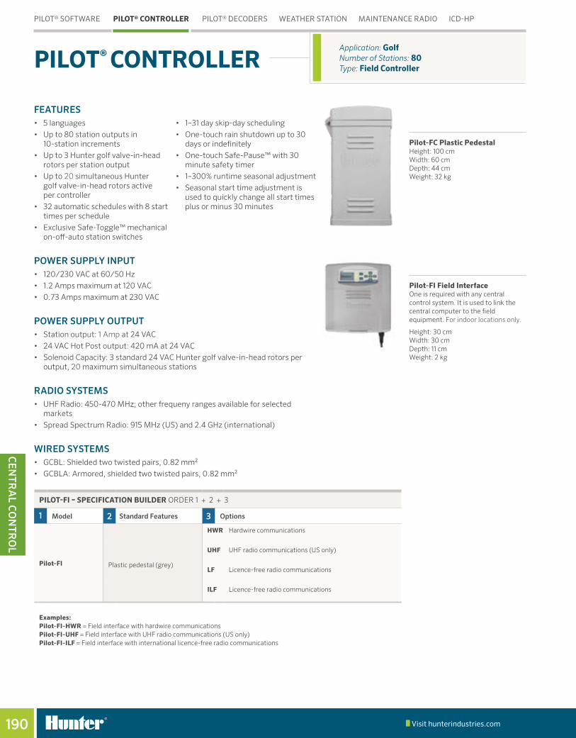
Application: Golf Number of Stations: 80Type: Field ControllerPILOT® CONTROLLER
Pilot-FC Plastic PedestalHeight: 100 cm Width: 60 cm Depth: 44 cm Weight: 32 kg
Pilot-FI Field InterfaceOne is required with any central control system. It is used to link the central computer to the field equipment. For indoor locations only.
Height: 30 cm Width: 30 cm Depth: 11 cm Weight: 2 kg
PILOT-FI – SPECIFICATION BUILDER ORDER 1 + 2 + 3
1 Model 2 Standard Features 3 Options
Pilot-FI Plastic pedestal (grey)
HWR Hardwire communications
UHF UHF radio communications (US only)
LF Licence-free radio communications
ILF Licence-free radio communications
Examples:Pilot-FI-HWR = Field interface with hardwire communicationsPilot-FI-UHF = Field interface with UHF radio communications (US only)Pilot-FI-ILF = Field interface with international licence-free radio communications
PILOT® SOFTWARE PILOT® CONTROLLER PILOT® DECODERS WEATHER STATION MAINTENANCE RADIO ICD-HP
Table of Contents:Pilot® Controller
Cross References:Systems Pilot Controller

Visit hunterindustries.com 191
CEN
TRA
L C
ON
TRO
L
GOLF IRRIGATION | Built on Innovation®
THE PILOT® FIELD CONTROLLER WAS BUILT SPECIFICALLY FOR GOLF COURSE IRRIGATION CONTROL.
Water-Resistant KeypadLarge backlit display with convenient
function buttons for the most commonly used features. Built-in
system diagnostics make trouble-shooting your system a breeze.
Easy to ServiceThe only tool required is a Phillips screwdriver included with every controller.
Modular 10-Station Expansion Boards Colour-coded modular components with captured screws so they won’t get lost, making it easy to assemble and troubleshoot.
Spacious Wiring Area No exposed circuitry or loose wires.All circuit boards are encapsulated in polyurethane to protect them from moisture, insects and temperature extremes.
Auto/On/Off Switches and Diagnostic LED Indicators
Standard for all station outputs, provide quick troubleshooting
and watering tools.
Conveniently Located Dual-Voltage (120/230 VAC) Junction Box
Features heavy duty surge protection and even includes a spare fuse.
PILOT-FC – SPECIFICATION BUILDER ORDER 1 + 2 + 3
1 Model 2 Standard Features 3 Options
Pilot-FC30 (30-station) S Stand-alone field controller with no central communications
Pilot-FC40 (40-station) HWR Hardwire communications
Pilot-FC50 (50-station) Plastic pedestal (grey) UHF UHF radio communications (US only)
Pilot-FC60 (60-station)120/230 VAC 60/50 Hz dual-voltage transformer
LF Licence-free spread spectrum radio communications (900 MHz for North America and where permitted)
Pilot-FC70 (70-station) ILF Licence-free spread spectrum radio communications (2.4 GHz for international, where permitted)
Pilot-FC80 (80-station)
Examples:Pilot-FC40-S = 40-station, stand-alone field contraoller with no central communicationsPilot-FC70-HWR = 70-station field controller with hardwire communications Pilot-FC80-ILF = 80-station field controller with international licence-free radio communications
PILOT® SOFTWARE PILOT® CONTROLLER PILOT® DECODERS WEATHER STATION MAINTENANCE RADIO ICD-HP

Visit hunterindustries.com192
CEN
TRA
L CO
NTR
OL
Decoder installations continue to be one of the fastest growing forms of technology in irrigation control. A key advantage over conventional systems is that decoders use less wire for an overall irrigation system. That means lower cost, quicker installation time, and easier system diagnosis and repair if needed. Systems can be easily expanded—with minimal digging and disruption of landscaping—by adding in more decoders rather than running additional wires.
Pilot enables you to take advantage of this cost-efficient approach. Pilot decoders are available with 1, 2, 4 and 6-station outputs, making it possible to run each head on an entire green with a single decoder. In all, decoders let you operate up to 999 stations out to 4.5 km from a single hub.
Pilot decoder systems include built-in surge suppression, colour-coded wire connections, true independent station control, programmable station addresses, and two-way feedback to the controller with confirmation and status indication.
Pilot-SG surge protectors are required when a system is designed and installed with Decoder-In-Head (DIH) rotors.
PILOT® DECODERS Application: GolfNumber of Stations: 999 Type: Decoder System
Water-Resistant KeypadBacklit display and secondary LED facepack means it can be used day or night
Diagnostic LED IndicatorsFor all functions on decoder output module
250-Station Output Modules Enable your decoder hub to grow with your course. Start with 250 - grow to 999
Pilot Decoder Hub
Pilot Decoders1 & 2 Station Decoders: Height: 9 cm Width: 4 cm Depth: 2.5 cm Weight: 150 g 4 & 6 Station Decoders: Height: 9 cm Width: 4.5 cm Depth: 4 cm Weight: 250 g Distinct yellow design makes it much easier to find decoders in dark valve boxes or buried in the soil.
All DIH rotors include two IBM DBRY-6 splices for connection to the 2-wire path. DIH rotor control systems require grounding with Pilot-SG surge suppressors coupled to appropriate grounding plate or rod. Hunter recommends a minimum of one Pilot-SG for every 12 installed DIH rotors or as per project specification.
DS-G Surge Ground Arrestor
PILOT® SOFTWARE PILOT® CONTROLLER PILOT® DECODERS WEATHER STATION MAINTENANCE RADIO ICD-HP
PILOT-DH – SPECIFICATION BUILDER ORDER 1 + 2 + 3
1 Model 2 Standard Features 3 Options
Pilot-DH250 (250-station) S Stand-alone decoder hub with no central communications
Pilot-DH500 (500-station) HWR Hardwire communications
Pilot-DH750 (750-station)Plastic pedestal (grey)
UHF UHF radio communications (US only)
Pilot-DH999 (999-station)LF Licence-free spread spectrum radio communications
(900 MHz for North America and where permitted)
ILF Licence-free spread spectrum radio communications
(2.4 GHz for international, where permitted)
Examples:Pilot-DH250-S = 250-station, stand-alone decoder hub with no central communicationsPilot-DH750-ILF = 750-station decoder hub with international licence-free radio communicationsPilot-DH999-HWR = 999-station decoder hub with hardwire communications
Table of Contents:Pilot® Decoders
Cross References:

Visit hunterindustries.com 193
CEN
TRA
L C
ON
TRO
L
GOLF IRRIGATION | Built on Innovation®
Decoder-In-HeadHunter’s exclusive DIH golf rotor minimises valve box covers on playing surface
Extend control up to 4,5 km with a single pair of wires
Decoder in valve box Runs up to 45 m from decoder to solenoids
Expansion options If your course has over 999 stations, you can use up to 999 decoder hubs for 998,001 decoders
Pilot-DHProvides independent station control of 999 decoders with up to 120 running simultaneously
Surge ProtectionDecoder-In-Head systems require approximately one Pilot surge arrestor for every 12 decoders. The actual number will vary by system design
Wireless Programming!
Communicate with decoders directly through plastic case: wireless electro-magnetic induction saves waterproof connectors
See the ICD-HP on page 195
PILOT® SOFTWARE PILOT® CONTROLLER PILOT® DECODERS WEATHER STATION MAINTENANCE RADIO ICD-HP
DECODERS – SPECIFICATION BUILDER ORDER 1
1 Model 2 Standard Features
Pilot-100 1-station decoder Built-in surge protection
Pilot-200 2-station decoder DBRY-6 Waterproof Connectors includedPilot-400 4-station decoder
Pilot-600 6-station decoder
Pilot-SG Inline surge protection (for DIH rotor systems)
Example:Pilot-100 = 1-station decoder
Cross References:DBRY Ref

Visit hunterindustries.com194
CEN
TRA
L CO
NTR
OL
FEATURES• Includes built-in 60-day data logger: With onboard evapotranspiration (ET)
calculation (modified Penman-Monteith equation for turf grass)• Wireless package uses 2.4 GHz licence-free technology
- 2.4 GHz radio systems can reach up to 3 km - In rural areas, try the licence-free, 900 MHz radio for links up to 800 m
• Wired systems use Hunter GCBL, direct-bury cable with a range of 1.25 km (dedicated 9-pin serial computer port required)
• Optional solar panel kit provides wireless power - Simple installation and versatile mounting with on-board 800 mAh rechargeable gel cell battery with 18 VDC transformer and 7 m power cable.
• Weatherproof construction: With UV stabilised enclosure, weather-proof external connectors and long-life coated circuit boards
• UL, c-UL and CE certifications
TurfWeather StationHeight: 61 cm Width: 40.5 cm Depth: 38 cm Weight: 6 kg
Application: GolfRange: Wireless 1 kmType: Weather StationWEATHER STATION
PILOT® SOFTWARE PILOT® CONTROLLER PILOT® DECODERS WEATHER STATION MAINTENANCE RADIO ICD-HP
COMPLETE PACKAGES INCLUDE HUNTER WEATHER SOFTWARE
Model Description
TWHW Wired communications to central computer – GCBL cable is required
TW24 2.4 GHz licence-free radio communication to central computer
TW916 916 MHz licence-free radio communication to central computer
TW922A 922 MHz licence-free radio communication to central computer
TWSUN Optional solar power kit for all TurfWeather models
Table of Contents:Weather Station
Cross References:

Visit hunterindustries.com 195
CEN
TRA
L C
ON
TRO
L
GOLF IRRIGATION | Built on Innovation®
FEATURES• Instant control of stations, blocks and programs• Fewer buttons to push• Instant audio confirmation of commands• Hunter’s famous StraightTalk™ Technology: Enables wireless
remote control at ranges up to 3.5 km whether or not the central computer is turned on
• Easy commands that show in display before sending• Compact size, industrial construction• Suitable for two-way voice communication with crews and office• High signal output: 2 watts, UHF (450–470 MHz)*
* Note: Licence required in most countries
TRNR RadioHeight: 10.25 cm Width: 5.25 cm Depth: 3 cm Weight: 200 grams
Application: GolfRange: Up to 3.5 kmType: Remote ControlMAINTENANCE RADIO
FEATURES• Program or re-program decoder stations, whether new or installed• Program any station numbers in any order, or skip stations for
future expansion• Turn decoder stations on and view solenoid status, current in milliamps,
and more• Built-in voltmeter for decoder path• Communicates with decoders directly through plastic case: wireless
electro-magnetic induction saves waterproof connectors• Communicates through the top of DIH rotors- no cover
removal required
Type: Decoder ProgrammerICD-HP
ICD-HP
WIRELESS HANDHELD DECODER PROGRAMMER
ICD-HPHeight: 21 cm Width: 9 cm Depth: 5 cm
Packaged in an outdoor carrying case, this complete kit includes probes, induction cup, cable, USB power cable for bench use, and 4 AA batteries for field work.
PILOT® SOFTWARE PILOT® CONTROLLER PILOT® DECODERS WEATHER STATION MAINTENANCE RADIO ICD-HP
Cross References:Maintenance Radio
ICD-HP

Hunter Residential & Commercial Irrigation
Hunter Industries Incorporated (“Hunter”) warrants the following products to be free of defects in materials or workmanship under normal use in landscape irrigation applications for the specified period of time outlined below from the original date of manufacture:
ONE YEAR
ROTORS SRM MICRO Micro Sprays, PLD Fittings, PLD-LOC Fittings, Rigid Risers
TWO YEARS
ROTORS PGP®-ADJ, PGJ CONTROLLERS Eco Logic, XC Hybrid, HC Controller, X-Core® and Pro-C® Families, ROAM, NODE, WVP, WVC, PSR
SPRAYS PS Ultra Family SENSORS ET System, Wireless Flow Sensor
NOZZLES Spray Nozzles, PCN, PCB, AFB, MSBN MICRO ACZ, PCZ, RZWS, Point Source Emitters, Tubing, Multi-Port Emitters, IH Risers, MLD, Eco-Indicator
VALVES PGV Family, PSR ACCESSORIES HCV, SJ, FLEXsg, HSBE Family, SpotShot, RZA
THREE YEARS CONTROLLERS ROAM XL MP ROTATOR® All
FIVE YEARS
ROTORS PGP Ultra, I-20, I-25, I-40, and I-90 Families
CENTRAL IMMS® Central Control Products
SPRAYS Pro-Spray®, Pro-Spray PRS30, and Pro-Spray PRS40 Families
SENSORS Clik Sensors, Solar-Sync®, Flow-Sync®, MWS
VALVES HQ, ICV, IBV MICRO ICZ, PLD Tubing, Eco-Mat®, Eco-Wrap™
CONTROLLERS I-Core®/DUAL® and ACC controller families, ICD and Dual Decoder Products, ICR Remotes, ICC2
Hunter Golf and ST System Irrigation Component* Warranty Products
Hunter will unconditionally repair, replace or repurchase, at its sole discretion, any defective component* assemblies contained within the Golf and ST products listed below by category, returned freight prepaid, from the date of manufacture within a period of:
ONE YEAR
GOLF CONTROLLERS
Pilot® Software, Pilot-FC, Pilot-FI, Pilot Hub
THREE YEARS
GOLF ROTORS B Series, G800 Series, G900 Series, RT Series
GOLF DECODERS Pilot 100, Pilot 200, Pilot 400, Pilot 600,
GOLF ROTORS Golf rotor component warranty extended to 5-years with one-for-one purchase of HSJ Swing Joint from authorized Hunter Golf distributor.
FIVE YEARS
SWING JOINTS HSJ-0, HSJ-1, HSJ-2, HSJ-3
ST ROTORS ST-90, STG-900, ST-1200, ST-1600
ST ACCESSORIES All model number starting with "ST"
COMPUTER, PRINTERS & ACCESSORIES, MAINTENANCE RADIO & BATTERY
Equipment manufacturer’s warranty (no Hunter warranty)
STATEMENT OF WARRANTY
* Warranty covers repair, replacement or repurchase of individual defective component assemblies contained within the product. Returns of complete finished goods are not allowed under warranty without prior approval from the Hunter Product Manager.
If used for agricultural applications, Hunter limits the warranty for its spray, rotator and rotor products to a period of one (1) year from original date of manufacture. This agriculture limitation supersedes all other warranties expressed or implied. Hunter warrants the battery life of the Wireless Rain-Clik and Wireless Solar Sync sensors for 10 years.

If a defect in a Hunter product is discovered during the applicable warranty period, Hunter will repair or replace, at its option, the product or the defective part. This warranty does not extend to repairs, adjustments, or replacement of a Hunter product or part that results from misuse, negligence, alteration, modification, tampering, or improper installation and/or maintenance of the product. This warranty extends only to the original installer of the Hunter product. If a defect arises in a Hunter product during the warranty period, contact your local Hunter Authorized Distributor.
Hunter’s warranty applies only to products installed as specified and used as intended for irrigation purposes. Hunter’s warranty shall be limited to defects in materials and workmanship during the warranty period, and shall not extend to situations in which the product was subjected to improper design, installation, operation, maintenance, application, abuse, improper electrical current, grounding, service other than by Hunter authorized agents, operating conditions other than that for which it was designed, or in systems using water containing corrosive chemicals, electrolytes, sand, dirt, silt, rust or agents that otherwise attack and degrade plastics. Hunter’s warranty does not cover component failures caused by lightning strikes, electrical power surges or unconditioned power supplies. If products are repurchased, the price to Distributor for such products in effect at the time of return will apply.
Hunter’s obligation to repair, replace or repurchase its products or product components as set forth above is the sole and exclusive warranty extended by Hunter. There are no other warranties, expressed or implied, including warranties of merchantability and warranties of fitness for a particular purpose. Hunter will not be liable to a distributor or to any other party in strict liability, tort, contract or any other manner for any damages caused or claimed to be caused as a result of any design of or defect in Hunter’s products, or for any special, incidental or consequential damages of any nature.
Where applicable, Hunter’s statement of warranty complies with local directives.
If you have any questions concerning the warranty or its application, please email [email protected].
ASAE CERTIFICATION STATEMENT
Hunter Industries Incorporated certifies that pressure, flow rate, and radius data for these products were determined and listed in accordance with ASAE Standard S398.1, Procedure for Sprinkler Testing and Performance Reporting, and are representative of performance of production sprinklers at the time of publication. Actual product performance may differ from the published specifications due to normal manufacturing variations and sample selection. All other specifications are solely the recommendation of Hunter Industries Incorporated.
®
Statement of Warranty Continued

© 2016 Hunter Industries Incorporated Please recycle.
USA HEADQUARTERS 1940 Diamond StreetSan Marcos, California 92078, USA TEL: +1 760-744-5240
MEXICO MANUFACTURINGISO 9001:2008 Certified Calle Nordika #8615Tijuana, B.C., Mexico C.P., 22640 TEL: +52 664-903-1300 FAX: +52 664-903-1325
EUROPE Avda. Diagonal 523, 5°- 2° Edificio Atalaya 08029 Barcelona, Spain TEL: +34 9-34-94-88-81
AUSTRALIA Suite 7, 202 Ferntree Gully Road Notting Hill, Melbourne, Victoria 3168, Australia TEL: +61 3-9562-9918 FAX: +61 3-9558-6983
MIDDLE EAST P.O. Box 2370Amman, 11941, JordanTEL: +962 6-5152882FAX: +962 6-5152992
CHINA B1618, Huibin Office Bldg. No.8, Beichen Dong Street Beijing 100101, China TEL/FAX: +86 10-84975146
GI-001 US 11/16
Website www.hunterindustries.com | Customer Support +1 800-383-4747 | Technical Service +1 760-591-7383
Helping our customers succeed is what drives us. While our passion
for innovation and engineering is built into everything we do, it is our
commitment to exceptional support that we hope will keep you in
the Hunter family of customers for years to come.
Gregory R. Hunter, President of Hunter Industries