Hunter Golf Irrigation
34
137 GOLF IRRIGATION GOLF IRRIGATION SECTION 10:
-
Upload
the-farbetek-group -
Category
Documents
-
view
222 -
download
0
description
Selected info for Golf course irrigation from Hunter
Transcript of Hunter Golf Irrigation

137
go
lf irr
iga
tion
goLF IrrIgatIonSECTIOn 10:

138
go
lf ir
rig
ati
on
goLF IrrIgatIonThe G885 takes drive torque to a whole new level
in golf rotors. This powerful adjustable arc and true
full circle rotor is packed with performance,
efficiency and every feature you expect in
modern-day golf rotors.
The all-new Pilot Central Control System is the new standard in advanced control. It puts the superintendent in complete command, and crews in the position to work faster and easier.
Upgrade your Hunter golf rotors to a 5-Year
component exchange warranty with the matching
purchase of HSJ Swing Joints.
g885 Rotor
pilot Control system
HsJ swing Joints
WHaT'S nEW

139
go
lf ro
tor
s
goLF rotors
the next generation rotor
The G885 includes an innovative combination of user-friendly features and benefits for the golf
course superintendent.
140
go
lf r
oto
rs
GoLF RotoRS
aDVanCED FEaTUrESG885 GoLF RotoR
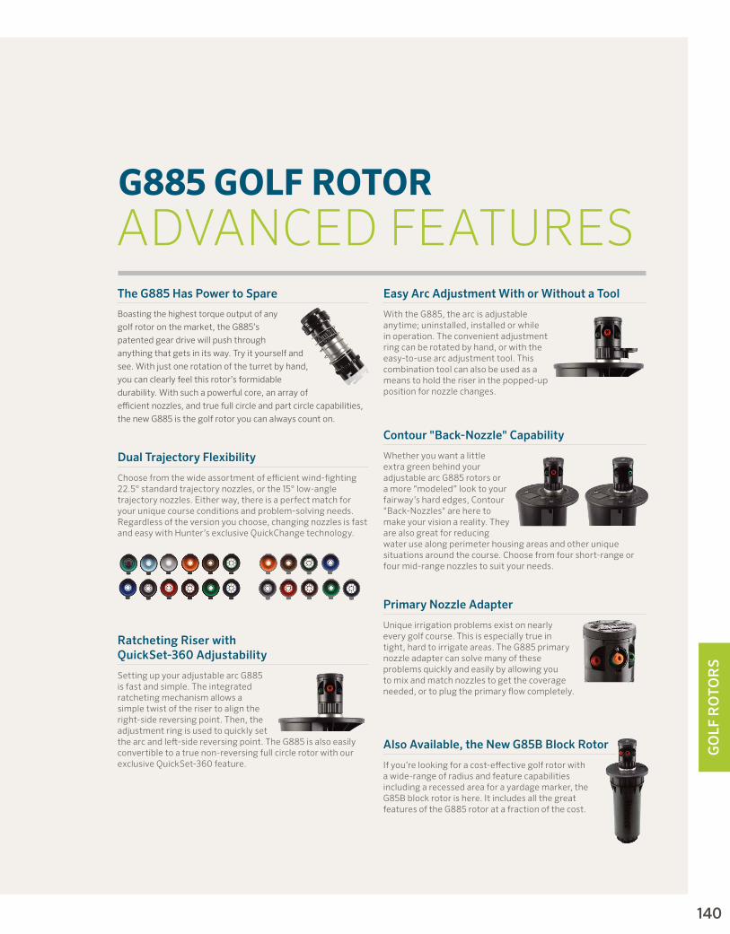
the g885 Has power to spare
Boasting the highest torque output of any
golf rotor on the market, the G885’s
patented gear drive will push through
anything that gets in its way. Try it yourself and
see. With just one rotation of the turret by hand,
you can clearly feel this rotor’s formidable
durability. With such a powerful core, an array of
efficient nozzles, and true full circle and part circle capabilities,
the new G885 is the golf rotor you can always count on.
primary nozzle adapter
Unique irrigation problems exist on nearly every golf course. This is especially true in tight, hard to irrigate areas. The G885 primary nozzle adapter can solve many of these problems quickly and easily by allowing you to mix and match nozzles to get the coverage needed, or to plug the primary flow completely.
also available, the new g85B Block Rotor
If you’re looking for a cost-effective golf rotor with a wide-range of radius and feature capabilities including a recessed area for a yardage marker, the G85B block rotor is here. It includes all the great features of the G885 rotor at a fraction of the cost.
Contour "Back-nozzle" Capability
Whether you want a little extra green behind your adjustable arc G885 rotors or a more “modeled” look to your fairway’s hard edges, Contour "Back-Nozzles" are here to make your vision a reality. They are also great for reducing water use along perimeter housing areas and other unique situations around the course. Choose from four short-range or four mid-range nozzles to suit your needs.
easy arc adjustment With or Without a tool
With the G885, the arc is adjustable anytime; uninstalled, installed or while in operation. The convenient adjustment ring can be rotated by hand, or with the easy-to-use arc adjustment tool. This combination tool can also be used as a means to hold the riser in the popped-up position for nozzle changes.
dual trajectory Flexibility
Choose from the wide assortment of efficient wind-fighting 22.5° standard trajectory nozzles, or the 15° low-angle trajectory nozzles. Either way, there is a perfect match for your unique course conditions and problem-solving needs. Regardless of the version you choose, changing nozzles is fast and easy with Hunter’s exclusive QuickChange technology.
Ratcheting Riser with Quickset-360 adjustability
Setting up your adjustable arc G885 is fast and simple. The integrated ratcheting mechanism allows a simple twist of the riser to align the right-side reversing point. Then, the adjustment ring is used to quickly set the arc and left-side reversing point. The G885 is also easily convertible to a true non-reversing full circle rotor with our exclusive QuickSet-360 feature.

141
go
lf ro
tor
s
ttS GoLF RotoRSaDVanCED FEaTUrES
Total-Top-Service (TTS)
access everything through the top
The no-dig solution is appreciated by golfers, management, and especially the superintendent
pilot Valve Freeze suppression unit
Patented FST technology prevents freeze damage— another TTS exclusive
two-stage Filtration in Valve Circuitry
Anti-contamination filters in pilot valve and inlet valve protect critical valve-in-head passages
large and Flexible yardage marker Capabilities
Recessed area for placard markers; optional raised marker for popular engraved and paint-filled markers
Patented Freeze Suppression
Technology
Stage 2 Filtration
Stage 1 Filtration
unitised inlet Valve assembly
Easy one-step removal of rock screen, valve seat and assembly
upper snap Rings with integrated Wiper seal
Protects rotor’s riser seal from external contamination such as sand top-dressing
Convenient Circular Flange design
Offset riser and compartment allows quick and easy trimming around the rotor with motorised equipment
through-the-top servicing of on-off-auto selector
Simple and inexpensive to replace, should damage occur

142
go
lf r
oto
rs
made in the usa
Concealed adjustable pressure Regulation
Stored within the flange compartment, prevents accidental adjustments
through-the-top solenoid Connections
Keeps wire splices protected in valve-box conditions with easy solenoid servicing
stainless steel seat in pilot Valve
Durable and corrosion-free, helps prevent slow leaks and weeping in the rotor
proudly manufactured in the usa
Hunter is the only leading irrigation manufacturer making golf rotors in the United States of America

143
go
lf ro
tor
s
decoders are Built into Rotors
Perfect package to complement decoder control systems. All DIH rotors include two DBR/Y-6 splice connectors
state-of-the-art surge suppression
Earth grounding is easily added with the Pilot SG surge protector
seamless no-splice Connection Between decoder and solenoid
With no connectors, maintains ongoing electrical continuity and peace of mind
individual decoder and solenoid Components Within Flange Compartment
Isolated configuration minimises maintenance costs year after year and into the future
DIH GoLF RotoRSaDVanCED FEaTUrES
Decoder-In-Head (DIH)
made in the usa

144
go
lf r
oto
rs
aDVanCED FEaTUrES
new two-station diH Rotor option
Perfect cost-effective solution for back-to-back heads around greens
program decoders from the surface with no disassembly
Simple, fast and easy to program before or after installation
access decoders through the top with no digging Required
Servicing is a breeze and there’s no mess with TTS DIH rotors
durability, efficiency, and Reliability Housed in the only tts diH Rotor in the industry
Peace of mind from the #1 producer of gear-driven rotors in the world
Built strong in the united states of america
Among the top three irrigation manufacturers, Hunter is the only one making golf rotors in the USA
diH Rotors include all the exclusive Features and Benefits of tts Rotors
When you can access everything through the top, you never have to touch the turf
decoders are Housed in the diH Rotor’s unique Flange Compartment
Improves playability and eliminates hundreds of unsightly decoder enclosures course-wide

145
go
lf ro
tor
s
Visit hunterindustries.com.au
FeatuRes• Models:
- G990 – Full circle - G995 – Adjustable arc (40° - 360°)
• QuickCheck arc mechanism• Dual trajectory nozzle choices:
- 8 standard trajectory (22.5°) - 8 low angle trajectory (15°)
• Nozzle range: #25 to #73• Exclusive PressurePort™ nozzle
technology• Contour “Back-Nozzle” capabilities• Water lubricated gear-drive► All TTS advanced features► Decoder-In-Head (DIH) capable
opeRating speCiFiCations• G990
- Radius: 22.3 to 31.4 m - Flow: 6.93 to 18.92 m3/hr; 115.5 to 315.3 l/min - Pressure range: 5.5 to 8.3 bar; 551 to 827 kPa
• G995 - Radius: 22.9 to 31.7 m - Flow: 6.7 to 19.04 m3/hr; 111.7 to 317.2 l/min - Pressure range: 5.5 to 8.3 bar; 550 to 830 kPa
• All TTS rotors are pressure rated at 10 bar; 1,000 kPa
options• C – Check-O-Matic checks up to 8 m in elevation change and readily
converts to Normally Open Hydraulic with through the top connections• D – Decoder Valve-In-Head with all “E” specifications below• DD – Two-station Decoder Valve-In-Head with all "E" specifications below• E – Electric Valve-In-Head with adjustable pressure regulation, on-off-auto
selector, 210mA (370mA inrush) solenoid with captive plunger and internal downstream bleed
► = TTS and DIH Advanced Features detailed on pages 141 and 143
g900 serIes G800 SERIES B SERIES RT SERIES SWING JOINTS
G990CPop-up height: 8 cmOverall height: 34 cm Flange diameter: 19 cmFemale Inlet: 1½" ACME
G995ePop-up height: 8 cmOverall height: 34 cm Flange diameter: 19 cmFemale Inlet: 1½" ACME
G900 SeRIeSModels: G990 & G995Radius: 22.3 to 31.7 mFlow: 6.7 to 19.04 m3/hr; 111.7 to 317.2 l/min
G990 & G995 – SPeCIFICatIoN bUILDeR: ORDER 1 + 2 + 3 + 4 + 5
1 model 2 Valve options 3 nozzle 4 Regulation* 5 options
G990 = Full Circle C = Check-O-Matic* 25 to 73 = Installed G990 Nozzle* P8 = 80 PSI (nozzles 25 to 53) S = SSU*
D = Decoder Valve-In-Head P1 = 100 PSI (nozzles 53 to 73)
DD = Two-station Decoder Valve-In-Head P2 = 120 PSI (nozzle 73)
e = Electric Valve-In-Head
G995 = Adjustable Arc 40° - 360° C = Check-O-Matic* 25 to 73 = Installed G995 Nozzle* P8 = 80 PSI (nozzles 25 to 53) S = SSU*
D = Decoder Valve-In-Head P1 = 100 PSI (nozzles 53 to 73)
DD = Two-station Decoder Valve-In-Head P2 = 120 PSI (nozzle 73)
e = Electric Valve-In-Head
* Converts to N.O. Hydraulic Valve-In-Head* SSU = #25 or #53 * SSU = P8/#25
P8/#53* Standard Stocking Unit
example: g990 - e - 53 - p8 - s = G990 full circle electric valve-in-head, installed #53 nozzle, 80 PSI regulation, standard stocking unit model

146golf IrrIgatIon | Built on Innovation
go
lf r
oto
rs
Visit hunterindustries.com.au
g900 serIes G800 SERIES B SERIES RT SERIES SWING JOINTS
Contour “Back-nozzle” Capabilities
Choose any nozzle from the PGP, I-40, and G70 nozzle racks, or from the short and mid-range G900 nozzles.
G990 NozzLe PeRFoRMaNCe Data*
nozzle pressure Radius** m
Flow precip mm/hr bar kPa m3/hr l/min
255.5 551 22.3 6.93 115.2 14.0 16.26.2 620 22.9 7.36 122.6 14.1 16.3
Lt. Blue 6.9 689 23.2 7.79 129.8 14.5 16.8
7.6 758 23.8 8.29 138.2 14.7 16.98.3 827 24.1 8.72 145.4 15.0 17.4
335.5 551 23.5 8.25 137.4 15.0 17.36.2 620 23.8 8.72 145.4 15.4 17.8
Grey 6.9 689 24.4 9.22 153.7 15.5 17.9
7.6 758 24.7 9.70 161.6 15.9 18.48.3 827 25.0 10.20 170.0 16.3 18.9
385.5 551 24.4 9.22 153.7 15.5 17.96.2 620 25.0 9.75 162.4 15.6 18.0
red 6.9 689 25.3 10.29 171.4 16.1 18.6
7.6 758 25.9 10.84 180.6 16.1 18.68.3 827 26.2 11.40 190.0 16.6 19.2
435.5 551 25.3 10.49 174.9 16.4 18.96.2 620 25.6 11.04 184.0 16.8 19.4
Dk. Brown 6.9 689 25.9 11.56 192.7 17.2 19.9
7.6 758 26.2 12.13 202.1 17.7 20.48.3 827 26.5 12.70 211.6 18.1 20.8
485.5 551 26.2 11.27 187.8 16.4 18.96.2 620 27.1 11.93 198.7 16.2 18.7
Dk. Green 6.9 689 27.4 12.45 207.4 16.5 19.1
7.6 758 27.7 13.02 216.9 16.9 19.58.3 827 28.0 13.52 225.2 17.2 19.8
535.5 551 27.1 12.31 205.2 16.7 19.36.2 620 27.4 12.88 214.6 17.1 19.8
Dk. Blue 6.9 689 28.0 13.45 224.1 17.1 19.7
7.6 758 28.3 14.02 233.6 17.4 20.18.3 827 28.7 14.58 243.0 17.8 20.5
635.5 551 28.0 14.36 23.92 18.3 21.16.2 620 28.7 14.97 249.5 18.2 21.1
Black 6.9 689 29.3 15.76 265.7 18.4 21.3
7.6 758 29.6 16.36 272.5 18.7 21.68.3 827 29.9 17.01 283.5 19.1 22.0
735.5 551 29.3 16.38 272.9 19.1 22.16.2 620 29.9 17.04 283.9 19.1 22.0
Orange 6.9 689 30.2 17.67 297.5 19.4 22.4
7.6 758 31.1 18.29 304.7 18.9 21.88.3 827 31.4 18.92 315.3 19.2 22.2
* Complies to aSaE standard. all precipitation rates calculated for 360˚ operation. all triangular rates are equilateral.
G995 NozzLe PeRFoRMaNCe Data*
nozzle pressure Radius** m
Flow precip mm/hr Bar kPa m3/hr l/min
255.5 551 22.9 6.70 111.7 12.8 14.86.2 620 23.2 7.16 119.2 13.3 15.4
Lt. Blue 6.9 689 23.5 7.54 125.7 13.7 15.8
7.6 758 23.8 8.09 134.8 14.3 16.58.3 827 24.1 8.52 142.0 14.7 17.0
335.5 551 23.5 8.22 137.0 14.9 17.26.2 620 23.8 8.68 144.6 15.4 17.7
Grey 6.9 689 24.1 9.18 152.9 15.8 18.3
7.6 758 27.4 9.68 161.3 15.9 18.38.3 827 25.0 10.18 169.6 16.3 18.8
385.5 551 24.4 9.22 153.7 15.5 17.96.2 620 25.0 9.77 162.8 15.6 18.1
red 6.9 689 25.6 10.31 171.9 15.7 18.2
7.6 758 25.9 10.81 180.2 16.1 18.68.3 827 26.2 11.36 189.3 16.5 19.1
435.5 551 25.6 10.47 174.5 16.0 18.46.2 620 25.9 11.02 183.6 16.4 19.0
Dk. Brown 6.9 689 25.9 11.52 191.9 17.2 19.8
7.6 758 26.2 12.13 202.1 17.7 20.48.3 827 26.5 12.65 210.8 18.0 20.8
485.5 551 26.8 11.40 190.0 15.8 18.36.2 620 27.1 11.95 199.1 16.2 18.7
Dk. Green 6.9 689 27.4 12.52 208.6 16.6 19.2
7.6 758 28.0 13.06 217.7 16.6 19.28.3 827 28.0 13.74 229.0 17.5 20.2
535.5 551 27.7 12.47 207.8 16.2 18.76.2 620 27.7 12.99 216.5 16.9 19.5
Dk. Blue 6.9 689 28.0 13.52 225.2 17.2 19.8
7.6 758 28.3 14.11 235.1 17.6 20.38.3 827 28.0 14.63 243.8 18.6 21.5
635.5 551 28.3 14.15 235.8 17.6 20.36.2 620 28.7 14.88 247.9 18.1 20.9
Black 6.9 689 29.0 15.67 261.2 18.7 21.6
7.6 758 29.3 16.33 272.2 19.1 22.08.3 827 29.9 16.97 282.8 19.0 22.0
735.5 551 29.3 16.51 275.2 19.3 22.36.2 620 29.9 17.13 285.4 19.2 22.2
Orange 6.9 689 30.5 17.74 295.6 19.1 22.0
7.6 758 31.1 18.38 306.2 19.0 22.08.3 827 31.7 19.04 317.2 18.9 21.9
G900 NozzLeS
G990 & G995
G900 Low-aNGLe NozzLeS
G990 & G995**
** Low-angle nozzles reduce radius by 15%

147
go
lf ro
tor
s
Visit hunterindustries.com.au
FeatuRes• Model: G880 – Full circle• Nozzle choices: 6 standard trajectory (25°)• Nozzle range: #25 to #53• Exclusive PressurePort™ nozzle technology• Water lubricated gear-drive► All TTS advanced features► Decoder-In-Head (DIH) capable
opeRating speCiFiCations• Radius: 20.4 to 26.8 m • Flow: 5.11 to 13.15 m3/hr; 85.2 to 219.2 l/min• Pressure range: 4.5 to 6.9 bar; 450 to 690 kPa• All TTS rotors are pressure rated at 10 bar; 1,000 kPa
options• C – Check-O-Matic checks up to 8 m in elevation change and readily
converts to Normally Open Hydraulic with through the top connections• D – Decoder Valve-In-Head with all “E” specifications below• DD – Two-station Decoder Valve-In-Head with all "E" specifications below• E – Electric Valve-In-Head with adjustable pressure regulation, on-off-auto
selector, 210mA (370mA inrush) solenoid with captive plunger and internal downstream bleed
► = TTS and DIH Advanced Features detailed on pages 141 and 143
G900 SERIES g800 serIes B SERIES RT SERIES SWING JOINTS
G880CPop-up height: 8 cmOverall height: 30 cm Flange diameter: 18 cmFemale Inlet: 1½" ACME
G880ePop-up height: 8 cmOverall height: 30 cm Flange diameter: 18 cmFemale Inlet: 1½" ACME
Model: G880Radius: 20.4 to 26.8 mFlow: 5.11 to 13.15 m3/hr; 85.2 to 219.2 l/min
G800 SeRIeS
G880 – SPeCIFICatIoN bUILDeR: ORDER 1 + 2 + 3 + 4 + 5
1 model 2 Valve options 3 nozzle 4 Regulation* 5 options
G880 = Full Circle C = Check-O-Matic* 25 to 53 = Installed G880 Nozzle* P6 = 65 PSI (nozzle 25 only) S = SSU*
D = Decoder Valve-In-Head P8 = 80 PSI (nozzles 25 to 53)
DD = Two-station Decoder Valve-In-Head
e = Electric Valve-In-Head
* Converts to N.O. Hydraulic Valve-In-Head * SSU = #25 or #48* SSU = P6/#25 P8/#25 P8/#48
* Standard Stocking Unit
example: g880 - e - 48 - p8 - s = G880 full circle electric valve-in-head, installed #48 nozzle, 80 PSI regulation, standard stocking unit model

148golf IrrIgatIon | Built on Innovation
go
lf r
oto
rs
Visit hunterindustries.com.au
G900 SERIES g800 serIes B SERIES RT SERIES SPOTSHOT
tts eQuals ConVenienCe and VeRsatility
With TTS, every serviceable component of the rotor can be easily accessed anytime with no servicing mess whatsoever.
G880 NozzLeS G880 NozzLe PeRFoRMaNCe Data*
nozzle pressure Radius m
Flow precip mm/hr Bar kPa m3/hr l/min
254.5 450 20.4 5.11 85.2 12.3 14.14.8 482 21.0 5.43 90.5 12.3 14.2
Lt. Blue 5.5 551 21.6 5.91 98.4 12.6 14.6
6.2 620 21.9 6.34 105.6 13.2 15.26.9 689 22.3 6.77 112.8 13.7 15.8
334.5 450 22.3 7.04 117.3 14.2 16.44.8 482 22.6 7.31 121.9 14.4 16.6
Grey 5.5 551 23.2 7.88 131.4 14.7 17.0
6.2 620 23.5 8.40 140.1 15.3 17.66.9 689 23.8 8.81 146.9 15.6 18.0
384.5 450 23.2 7.97 132.9 14.9 17.24.8 482 23.5 8.25 137.4 15.0 17.3
red 5.5 551 24.1 8.75 145.7 15.1 17.4
6.2 620 24.4 9.20 153.3 15.5 17.96.9 689 24.7 9.75 162.4 16.0 18.5
434.5 450 23.8 8.90 148.4 15.8 18.24.8 482 24.1 9.27 154.4 16.0 18.5
Dk. Brown 5.5 551 25.0 9.93 165.4 15.9 18.3
6.2 620 25.3 10.56 176.0 16.5 19.16.9 689 26.5 11.09 184.7 16.9 19.5
484.5 450 25.0 9.95 165.8 15.9 18.44.8 482 25.3 10.52 175.3 16.4 19.0
Dk. Green 5.5 551 25.9 11.13 185.5 16.6 19.1
6.2 620 26.2 11.79 196.5 17.2 19.86.9 689 26.5 12.36 205.9 17.6 20.3
534.5 450 25.3 10.65 177.5 16.6 19.24.8 482 25.6 11.15 185.9 17.0 19.6
Dk. Blue 5.5 551 26.5 11.95 199.1 17.0 19.6
6.2 620 26.8 12.45 207.4 17.3 20.06.9 689 26.8 13.15 219.2 18.3 21.1
* Complies to aSaE standard. all precipitation rates calculated for 360˚ operation. all triangular rates are equilateral.

149 Visit hunterindustries.com.au
go
lf ro
tor
s
FeatuRes• Model: G885 – True full circle/adjustable part circle (60° to 360°)• QuickCheck arc mechanism• QuickSet-360 arc mechanism• Dual trajectory colour-coded nozzles:
- 12 standard trajectory (22.5°) - 9 low-angle trajectory (15°)
• Nozzle range: #10 to #53• Exclusive PressurePort™ nozzle technology• Contour “Back-Nozzle” capabilities• Ratcheting stainless steel riser• Water lubricated gear-drive► All TTS advanced features► Decoder-In-Head (DIH) capable
opeRating speCiFiCations• Radius: 13.1 to 27.7 m • Flow: 1.86 to 13.06 m3/hr; 31.0 to 217.7 l/min• Pressure range: 3.4 to 6.9 bar; 340 to 690 kPa• All TTS rotors are pressure rated at 10 bar; 1,000 kPa
options• C – Check-O-Matic checks up to 8 m in elevation change and readily
converts to Normally Open Hydraulic with through the top connections• D – Decoder Valve-In-Head with all “E” specifications below• DD – Two-station Decoder Valve-In-Head with all "E" specifications below• E – Electric Valve-In-Head with adjustable pressure regulation, on-off-auto
selector, 210mA (370mA inrush) solenoid with captive plunger and internal downstream bleed
► = TTS and DIH Advanced Features detailed on pages 141 and 143
G900 SERIES g800 serIes B SERIES RT SERIES SWING JOINTS
G885CPop-up height: 9.5 cmOverall height: 30 cm Flange diameter: 18 cmFemale Inlet: 1½" ACME
G885ePop-up height: 9.5 cmOverall height: 30 cm Flange diameter: 18 cmFemale Inlet: 1½" ACME
Model: G885Radius: 13.1 to 27.7 mFlow: 1.86 to 13.06 m3/hr; 31.0 to 217.7 l/min
G800 SeRIeS
G885 – SPeCIFICatIoN bUILDeR: ORDER 1 + 2 + 3 + 4 + 5
1 model 2 Valve options 3 nozzle 4 Regulation* 5 options
G885 = Full/Part Circle 60º-360º Arc Range
C = Check-O-Matic* 10 to 53 = Installed G885 Nozzle* P5 = 50 PSI (nozzles 10 to 18) S = SSU*
D = Decoder Valve-In-Head P6 = 65 PSI (nozzles 18 to 25)
DD = Two-station Decoder Valve-In-Head P8 = 80 PSI (nozzles 25 to 53)
e = Electric Valve-In-Head
* Converts to N.O. Hydraulic Valve-In-Head * SSU = #18, #23, #25 or #48 * SSU = P5/#18, P6/#23 P8/#25, P8/#48
* Standard Stocking Unit
example: g885 - e - 48 - p8 - s = G885 full/part circle electric valve-in-head, installed #48 nozzle, 80 PSI regulation, standard stocking unit model

150golf IrrIgatIon | Built on Innovation
go
lf r
oto
rs
Visit hunterindustries.com.au
G885 NozzLe PeRFoRMaNCe Data*
nozzle set pressure Radius
m
Flow precip mm/hr
bar kPa m3/hr l/min
Orange Dk. Green 3.4 344 13.1 1.86 31.0 10.8 12.54.1 413 13.4 2.23 37.1 12.4 14.3
10 4.5 450 13.7 2.29 38.2 12.2 14.1803603 315312 - - - - - - -
Lt. Green - - - - - - -Orange White 3.4 344 14.6 2.66 44.3 12.4 14.3
4.1 413 15.2 2.91 48.5 12.5 14.5
13 4.5 450 15.5 3.04 50.7 12.6 14.5803603 315314 - - - - - - -
Lt. Blue - - - - - - -Orange White 3.4 344 15.9 3.02 50.3 12.0 13.9
4.1 413 16.2 3.34 55.6 12.8 14.8
15 4.5 450 16.5 3.45 57.5 12.7 14.7803603 315314 - - - - - - -
White - - - - - - -Orange Lt. Green 3.4 344 16.8 3.79 63.2 13.5 15.6
4.1 413 17.4 4.04 67.4 13.4 15.5
18 4.5 450 17.7 4.13 68.9 13.2 15.3803603 315313 - - - - - - -
Orange - - - - - - -Orange Lt. Green 3.4 344 17.7 4.18 69.7 13.4 15.4
4.1 413 18.3 4.45 74.2 13.3 15.4
20 4.5 450 18.6 4.66 77.6 13.5 15.6803603 315313 4.8 482 18.6 4.88 81.4 14.1 16.3
Tan 5.5 551 18.9 5.13 85.6 14.4 16.6Orange Lt. Green 3.4 344 18.6 4.78 79.6 13.8 16.0
4.1 413 19.2 5.18 86.3 14.0 16.2
23 4.5 450 19.8 5.43 90.5 13.8 16.0803603 315313 4.8 482 20.1 5.86 97.7 14.5 16.7
Green 5.5 551 20.4 6.34 105.6 15.2 17.5Red Green 4.5 450 21.0 6.68 111.3 15.1 17.4
4.8 482 21.3 6.92 115.3 15.2 17.6
25 5.5 551 21.6 7.37 122.8 15.7 18.2803602 315310 6.2 620 21.9 7.77 129.5 16.1 18.6
Blue 6.9 689 22.3 8.25 137.4 16.7 19.2Red Green - - - - - - -
- - - - - - -
33 5.5 551 22.3 7.83 130.4 15.8 18.3803602 315310 6.2 620 22.6 8.34 138.9 16.4 18.9
Grey 6.9 689 23.2 8.75 145.7 16.3 18.8Red Green - - - - - - -
- - - - - - -
38 5.5 551 24.1 8.94 149.0 15.4 17.8803602 315310 6.2 620 24.1 9.36 156.0 16.1 18.6
Red 6.9 689 24.4 9.75 162.4 16.4 18.9Red Green - - - - - - -
- - - - - - -
43 5.5 551 24.4 9.88 164.7 16.6 19.2803602 315310 6.2 620 24.7 10.54 175.6 17.3 20.0
Dk. Brown 6.9 689 25.3 11.06 184.3 17.3 20.0Dk. Red Dk. Green - - - - - - -
- - - - - - -
48 5.5 551 25.9 11.20 186.6 16.7 19.3803601 315312 6.2 620 26.2 11.86 197.6 17.3 19.9
Dk. Green 6.9 689 26.8 12.43 207.1 17.3 19.9Dk. Red Dk. Green - - - - - - -
- - - - - - -
53 5.5 551 27.1 11.98 199.7 16.3 18.8803601 315312 6.2 620 27.4 12.54 209.0 16.7 19.2
Dk. Blue 6.9 689 27.7 13.06 217.7 17.0 19.6
= nozzle plug P/n 315300 installed in the back side of the nozzle housing.
* Preliminary performance data.
G900 SERIES g800 serIes B SERIES RT SERIES SWING JOINTS
Quickset-360 with Ratcheting Riser
Setting up your adjustable arc G885 is fast and simple. The integrated ratcheting mechanism allows a simple twist of the riser to align the right-side reversing point. The G885 is also easily convertible to a true non-reversing full circle rotor with our exclusive QuickSet-360 feature.
Contour “Back-nozzle” Capabilities
Whether you want a little extra green behind your adjustable-arc G885 rotors or a more “modeled” look to your fairway’s hard edges, Contour "Back-Nozzles" are here to make your vision a reality. Choose from four short-range or four mid-range nozzles to suit your needs.
G885 StaNDaRD NozzLeS G885 Low-aNGLe NozzLeS**
G885 CoNtoUR baCK-NozzLeS
** Low-angle nozzles reduce radius by 15%
CoNtoUR baCK-NozzLe PeRFoRMaNCe Data
p/n Colour profile4.5 Bar 5.5 Bar
Metres L/M Metres L/M
803604 Peach 7.6 12.9 8.2 14.8
803603 Orange 8.5 14.4 8.8 15.9
803602 Red 9.4 15.9 10.1 17.0
803601 Dk. Red 10.4 17.4 11.0 18.5
315314 White 11.3 10.6 11.6 11.0
315313 Lt. Green 12.8 16.3 13.4 17.8
315310 Green 14.0 19.7 14.6 21.6
315312 Dk. Green 14.9 29.9 15.5 33.3
Arc adjustment and riser hold-up tool
6

151 Visit hunterindustries.com.au
go
lf ro
tor
s
G835ePop-up height: 8 cmOverall height: 30 cm Flange diameter: 18 cmFemale Inlet: 1½" ACME
G835CPop-up height: 8 cmOverall height: 30 cm Flange diameter: 18 cmFemale Inlet: 1½" ACME
FeatuRes• Model:
- G835: Full/Part circle (50º to 360°)• QuickCheck arc mechanism• QuickSet-360 arc mechanism• Nozzle choices: 8 multi-trajectory (15° to 25°)• Nozzle range: #2 to #12• Water lubricated gear-drive► All TTS advanced features► Decoder-In-Head (DIH) capable
opeRating speCiFiCations• Radius: 5.5 to 15.2 m • Flow: 0.43 to 2.91 m3/hr; 7.2 to 48.5 l/min• Pressure range: 2.8 to 4.5 bar; 280 to 450 kPa• All TTS rotors are pressure rated at 10 bar; 1,000 kPa
options• C – Check-O-Matic checks up to 8 m in elevation change and readily
converts to Normally Open Hydraulic with through the top connections• D – Decoder Valve-In-Head with all “E” specifications below• DD – Two-station Decoder Valve-In-Head with all "E" specifications below• E – Electric Valve-In-Head with adjustable pressure regulation, on-off-auto
selector, 210mA (370mA inrush) solenoid with captive plunger and internal downstream bleed
► = TTS and DIH Advanced Features detailed on pages 141 and 143
G900 SERIES g800 serIes B SERIES RT SERIES SWING JOINTS
Model: G835Radius: 5.5 to 15.2 mFlow: 0.43 to 2.91 m3/hr; 7.2 to 48.5 l/min
G800 SeRIeS
G835 – SPeCIFICatIoN bUILDeR: ORDER 1 + 2 + 3 + 4 + 5
1 model 2 Valve options 3 nozzle 4 Regulation* 5 options
G835 = Full/Part Circle 50° - 360° C = Check-O-Matic* 6 = Installed G835 Nozzle*
P5 = 50 PSI (nozzles 2 to 12) S = SSU*
D = Decoder Valve-In-Head P6 = 65 PSI (nozzles 10 to 12)
DD = Two-station Decoder Valve-In-Head
e = Electric Valve-In-Head
* Converts to N.O. Hydraulic Valve-In-Head * Available in SSU models only
SSU = #6
Includes 8-nozzle rack
* SSU = P5/#6 * Standard Stocking Unit
example: g835 - e - 6 - p5 - s = G835 full/part circle electric valve-in-head, installed #6 nozzle, 50 PSI regulation, standard stocking unit model

152golf IrrIgatIon | Built on Innovation
go
lf r
oto
rs
Visit hunterindustries.com.au
spacious tts Flange Compartment
All TTS rotors include ample room for solenoid splice connections and a decoder module when needed.
G900 SERIES g800 serIes B SERIES RT SERIES SWING JOINTS
G835 NozzLe PeRFoRMaNCe Data*
nozzle pressure Radius m
Flow precip mm/hr bar kPa m3/hr l/min
22.8 275 5.5 0.43 7.2 14.3 16.63.4 344 6.1 0.48 7.9 12.8 14.8
Yellow 4.1 413 6.7 0.55 9.1 12.1 14.04.5 482 7.0 0.59 9.8 12.0 13.9
32.8 275 7.0 0.68 11.4 13.9 16.03.4 344 7.6 0.73 21.1 12.5 14.5
Yellow 4.1 413 8.2 0.80 13.2 11.7 13.64.5 450 8.5 0.82 13.6 11.2 13.0
42.8 275 7.6 0.89 14.8 15.3 17.63.4 344 8.5 0.93 15.5 12.8 14.8
Yellow 4.1 413 9.1 1.00 16.7 12.0 13.84.5 450 9.4 1.04 17.4 11.7 13.5
52.8 275 8.8 1.07 17.8 13.7 15.83.4 344 9.8 1.14 18.9 11.9 13.8
Yellow 4.1 413 10.1 1.20 20.1 11.9 13.74.5 450 10.7 1.23 20.4 10.8 12.4
62.8 275 9.8 1.36 22.7 14.3 16.53.4 344 10.7 1.43 23.8 12.6 14.5
Yellow 4.1 413 11.3 1.50 25.0 11.8 13.64.5 450 11.9 1.54 25.7 10.9 12.6
82.8 275 11.0 1.77 29.5 14.7 17.03.4 344 11.9 1.82 30.3 12.9 14.8
Yellow 4.1 413 12.8 1.89 31.4 11.5 13.34.5 450 13.1 1.93 32.2 11.2 13.0
102.8 275 11.9 2.20 36.7 15.6 18.03.4 344 13.1 2.29 38.2 13.4 15.4
Yellow 4.1 413 13.7 2.34 39.0 12.4 14.44.5 450 14.3 2.39 39.7 11.6 13.4
122.8 275 13.4 2.73 45.4 15.2 17.53.4 344 14.3 2.77 46.2 13.5 15.6
Yellow 4.1 413 14.6 2.84 47.3 13.3 15.34.5 450 15.2 2.91 48.5 12.5 14.5
G835 NozzLeS
G995 TTS Rotor
* Complies to aSaE standard. all precipitation rates calculated for 360° operation. all triangular rates are equilateral.

153
go
lf ro
tor
s
Visit hunterindustries.com.au
FeatuRes• Models:
- G80B: Full circle opposing nozzles - G85B: True full circle/adjustable part circle (60° to 360°)
• QuickCheckTM arc mechanism (G85B)• QuickSet-360 arc mechanism (G85B)• Dual trajectory colour-coded nozzles:
- G80B: 6 standard trajectory (25°) - G85B: 12 standard trajectory (22.5°) - G85B: 9 low-angle trajectory (15°)
• Nozzle range: - G80B: #25 to #53 - G85B: #10 to #53
• Exclusive PressurePort™ nozzle technology• Contour “Back-Nozzle” capabilities (G85B)• Ratcheting stainless steel riser (G85B)• Water lubricated gear-drives• Check height up to 3 m in elevation change
opeRating speCiFiCations• G80B
- Radius: 20.4 to 26.8 m - Flow: 5.11 to 13.15 m3/hr; 85.2 to 219.2 l/min - Pressure range: 4.5 to 6.9 bar; 450 to 690 kPa
• G85B - Radius: 13.1 to 27.7 m - Flow: 1.86 to 13.06 m3/hr; 31.0 to 217.7 l/min - Pressure range: 3.4 to 6.9 bar; 340 to 690 kPa
• All B Series rotors are pressure rated at 10 bar; 1,000 kPa
Models: G80b & G85bRadius: 13.1 to 27.7 mFlow: 1.86 to 13.15 m3/hr; 31.0 to 219.2 l/min
G900 SERIES G800 SERIES B serIes RT SERIES SWING JOINTS
b SeRIeS
G80bPop-up height: 8 cmOverall height: 24.5 cm Flange diameter: 13.7 cm Female Inlet: 1¼" ACME
G85bPop-up height: 9.5 cmOverall height: 24.5 cm Flange diameter: 13.7 cm Female Inlet: 1¼" ACME
G80b & G85b – SPeCIFICatIoN bUILDeR: ORDER 1 + 2 + 3 + 4
1 model 2 Valve options 3 nozzle 4 options*
G80 = Full Circle b = Block rotor with check valve 25 to 53 = Installed G80 Nozzle* S = SSU*
* SSU = #25 & #48 * Standard Stocking Unit
G85 = Futll/Part Circle 60° - 360° b = Block rotor with check valve 10 to 53 = Installed G85 Nozzle** S = SSU*
* * SSU = #18, #25 & #48 * Standard Stocking Unit
example: g80 - B - 25 - s = G80 full circle block rotor, installed #25 nozzle, standard stocking unit model

154golf IrrIgatIon | Built on Innovation
go
lf r
oto
rs
Visit hunterindustries.com.au
G85b NozzLe PeRFoRMaNCe Data*
nozzle set pressure Radius
m
Flow precip mm/hr
bar kPa m3/hr l/min
Orange Dk. Green 3.4 344 13.1 1.86 31.0 10.8 12.54.1 413 13.4 2.23 37.1 12.4 14.3
10 4.5 450 13.7 2.29 38.2 12.2 14.1803603 315312 - - - - - - -
Lt. Green - - - - - - -Orange White 3.4 344 14.6 2.66 44.3 12.4 14.3
4.1 413 15.2 2.91 48.5 12.5 14.5
13 4.5 450 15.5 3.04 50.7 12.6 14.5803603 315314 - - - - - - -
Lt. Blue - - - - - - -Orange White 3.4 344 15.9 3.02 50.3 12.0 13.9
4.1 413 16.2 3.34 55.6 12.8 14.8
15 4.5 450 16.5 3.45 57.5 12.7 14.7803603 315314 - - - - - - -
White - - - - - - -Orange Lt. Green 3.4 344 16.8 3.79 63.2 13.5 15.6
4.1 413 17.4 4.04 67.4 13.4 15.5
18 4.5 450 17.7 4.13 68.9 13.2 15.3803603 315313 - - - - - - -
Orange - - - - - - -Orange Lt. Green 3.4 344 17.7 4.18 69.7 13.4 15.4
4.1 413 18.3 4.45 74.2 13.3 15.4
20 4.5 450 18.6 4.66 77.6 13.5 15.6803603 315313 4.8 482 18.6 4.88 81.4 14.1 16.3
Tan 5.5 551 18.9 5.13 85.6 14.4 16.6Orange Lt. Green 3.4 344 18.6 4.78 79.6 13.8 16.0
4.1 413 19.2 5.18 86.3 14.0 16.2
23 4.5 450 19.8 5.43 90.5 13.8 16.0803603 315313 4.8 482 20.1 5.86 97.7 14.5 16.7
Green 5.5 551 20.4 6.34 105.6 15.2 17.5Red Green 4.5 450 21.0 6.68 111.3 15.1 17.4
4.8 482 21.3 6.92 115.3 15.2 17.6
25 5.5 551 21.6 7.37 122.8 15.7 18.2803602 315310 6.2 620 21.9 7.77 129.5 16.1 18.6
Blue 6.9 689 22.3 8.25 137.4 16.7 19.2Red Green - - - - - - -
- - - - - - -
33 5.5 551 22.3 7.83 130.4 15.8 18.3803602 315310 6.2 620 22.6 8.34 138.9 16.4 18.9
Grey 6.9 689 23.2 8.75 145.7 16.3 18.8Red Green - - - - - - -
- - - - - - -
38 5.5 551 24.1 8.94 149.0 15.4 17.8803602 315310 6.2 620 24.1 9.36 156.0 16.1 18.6
Red 6.9 689 24.4 9.75 162.4 16.4 18.9Red Green - - - - - - -
- - - - - - -
43 5.5 551 24.4 9.88 164.7 16.6 19.2803602 315310 6.2 620 24.7 10.54 175.6 17.3 20.0
Dk. Brown 6.9 689 25.3 11.06 184.3 17.3 20.0Dk. Red Dk. Green - - - - - - -
- - - - - - -
48 5.5 551 25.9 11.20 186.6 16.7 19.3803601 315312 6.2 620 26.2 11.86 197.6 17.3 19.9
Dk. Green 6.9 689 26.8 12.43 207.1 17.3 19.9Dk. Red Dk. Green - - - - - - -
- - - - - - -
53 5.5 551 27.1 11.98 199.7 16.3 18.8803601 315312 6.2 620 27.4 12.54 209.0 16.7 19.2
Dk. Blue 6.9 689 27.7 13.06 217.7 17.0 19.6
= nozzle plug P/n 315300 installed in the back side of the nozzle housing.
* Preliminary performance data.
G900 SERIES G800 SERIES B serIes RT SERIES SWING JOINTS
G80b NozzLe PeRFoRMaNCe Data*
nozzle pressure Radius m
Flow precip mm/hr bar kPa m3/ora l/min
254.5 450 20.4 5.11 85.2 12.3 14.14.8 482 21.0 5.43 90.5 12.3 14.2
Lt. Blue 5.5 551 21.6 5.91 98.4 12.6 14.6
6.2 620 21.9 6.34 105.6 13.2 15.26.9 689 22.3 6.77 112.8 13.7 15.8
334.5 450 22.3 7.04 117.3 14.2 16.44.8 482 22.6 7.31 121.9 14.4 16.6
Grey 5.5 551 23.2 7.88 131.4 14.7 17.0
6.2 620 23.5 8.40 140.1 15.3 17.66.9 689 23.8 8.81 146.9 15.6 18.0
384.5 450 23.2 7.97 132.9 14.9 17.24.8 482 23.5 8.25 137.4 15.0 17.3
red 5.5 551 24.1 8.75 145.7 15.1 17.4
6.2 620 24.4 9.20 153.3 15.5 17.96.9 689 24.7 9.75 162.4 16.0 18.5
434.5 450 23.8 8.90 148.4 15.8 18.24.8 482 24.1 9.27 154.4 16.0 18.5
Dk. Brown 5.5 551 25.0 9.93 165.4 15.9 18.3
6.2 620 25.3 10.56 176.0 16.5 19.16.9 689 26.5 11.09 184.7 16.9 19.5
484.5 450 25.0 9.95 165.8 15.9 18.44.8 482 25.3 10.52 175.3 16.4 19.0
Dk. Green 5.5 551 25.9 11.13 185.5 16.6 19.1
6.2 620 26.2 11.79 196.5 17.2 19.86.9 689 26.5 12.36 205.9 17.6 20.3
534.5 450 25.3 10.65 177.5 16.6 19.24.8 482 25.6 11.15 185.9 17.0 19.6
Dk. Blue 5.5 551 26.5 11.95 199.1 17.0 19.6
6.2 620 26.8 12.45 207.4 17.3 20.06.9 689 26.8 13.15 219.2 18.3 21.1
* Complies to aSaE standard. all precipitation rates calculated for 360˚ operation. all triangular rates are equilateral.
G80b NozzLeS G85b NozzLeS
G85b Low-aNGLe NozzLeS**
** Low-angle nozzles reduce radius by 15%

155
go
lf ro
tor
s
Visit hunterindustries.com.au
G900 SERIES G800 SERIES B serIes RT SERIES SWING JOINTS
b SeRIeS
FeatuRes• Models:
- G70B: Full circle - G75B: Full/Part circle (50° to 360°)
• QuickCheckTM arc mechanism (G75B)• QuickSet-360 arc mechanism (G75B)• Nozzle choices:
- G70B: 6 standard trajectory (25°) - G75B: 9 standard trajectory (25°)
• Nozzle range: - G70B: #15 to #28 - G75B: #8 to #28
• Exclusive PressurePort™ nozzle technology• Water lubricated gear-drive• Check height up to 3 m in elevation change
opeRating speCiFiCations• G70B
- Radius: 16.2 to 22.9 m - Discharge rate: 2.95 to 7.66 m3/hr; 49.2 to 127.6 l/min - Pressure range: 3.4 to 6.9 bars; 344 to 689 kPa
• G75B - Radius: 14.3 to 21.6 m - Discharge rate: 1.75 to 7.34 m3/hr; 29.1 to 122.3 l/m - Pressure range: 2.8 to 6.9 bars; 275 to 689 kPa
• All B Series rotors are pressure rated at 10 bars; 1,000 kPa
Models: G70b & G75b Radius: 14.3 to 22.9 mFlow Rate: 1.75 to 7.66 m3/hr; 29.1 to 127.6 l/min
b SeRIeS
G75bPop-up height: 8 cmOverall height: 23 cm Flange diameter: 12cmFemale Inlet: 1¼" ACME
G70bPop-up height: 8 cmOverall height: 23 cm Flange diameter: 12 cmFemale Inlet: 1¼" ACME
G70b & G75b - SPeCIFICatIoN bUILDeR: ORDER 1 + 2 + 3 + 4
1 model 2 Valve options 3 nozzle 4 options
G70 = Full Circle b = Block Rotor with Check Valve 25 = Installed G70 Nozzle *S = SSU *
* Available in SSU model only SSU = #25 Includes nozzle pack
* Standard Stocking Unit
G75 = Full/Part Circle, 50° - 360° Arc Range
b = Block Rotor with Check Valve 25 = Installed G75 Nozzle ** S = SSU *
** Available in SSU model only SSU = #25 Includes nozzle pack
* Standard Stocking Unit
example: g70 - B - 25 - s = G70 full circle block rotor, installed #25 nozzle with nozzle pack, standard stocking unit model

156golf IrrIgatIon | Built on Innovation
go
lf r
oto
rs
Visit hunterindustries.com.au
G900 SERIES G800 SERIES B serIes RT SERIES SWING JOINTS
G70b NozzLe PeRFoRMaNCe Data*
nozzle pressure Radius m
Flow precip mm/hr bar kPa m3/hr l/min
153.4 344 16.2 2.95 49.2 11.3 13.14.1 413 16.5 3.20 53.4 11.8 13.7
Grey 4.5 450 16.8 3.36 56.0 12.0 13.8
4.8 482 17.1 3.52 58.7 12.1 14.05.5 551 17.7 3.70 61.7 11.8 13.7
183.4 344 17.7 3.23 53.8 10.3 11.94.1 413 18.0 3.61 60.2 11.2 12.9
red 4.5 450 18.3 3.70 61.7 11.1 12.8
4.8 482 18.3 3.84 64.0 11.5 13.35.5 551 18.6 4.04 67.4 11.7 13.5
203.4 413 18.6 4.27 71.2 12.4 14.34.1 450 18.9 4.45 74.2 12.5 14.4
Dk. Brown 4.5 482 19.2 4.66 77.6 12.6 14.6
4.8 551 19.5 5.00 83.3 13.1 15.25.5 620 19.5 5.32 88.6 14.0 16.1
233.4 413 19.2 4.57 76.1 12.4 14.34.1 450 19.8 4.77 79.5 12.2 14.0
Dk. Green 4.5 482 19.8 4.97 82.9 12.7 14.6
4.8 551 20.1 5.32 88.6 13.1 15.25.5 620 20.4 5.66 94.3 13.6 15.7
253.4 413 19.8 4.95 82.5 12.6 14.64.1 450 20.4 5.11 85.2 12.3 14.1
Dk. Blue 4.5 482 20.4 5.36 89.3 12.9 14.8
4.8 551 21.0 5.75 95.8 13.0 15.05.5 620 21.6 6.11 101.8 13.0 15.1
284.8 482 21.6 6.38 106.4 13.6 15.75.5 551 21.6 6.79 113.2 14.5 16.7
Black 6.2 620 22.3 7.22 120.4 14.6 16.86.9 689 22.9 7.66 127.6 14.6 16.9
* Complies to aSaE standard. all precipitation rates calculated for 360˚ operation. all triangular rates are equilateral.
G75b NozzLe PeRFoRMaNCe Data*
nozzle pressure Radius m
Flow precip mm/hr bar kPa m3/hr l/min
82.8 275 14.3 1.75 29.1 8.5 9.83.4 344 14.9 1.89 31.4 8.5 9.8
Lt. Brown 4.1 413 15.2 2.09 34.8 9.0 10.4
4.5 450 15.2 2.16 36.0 9.3 10.74.8 482 15.5 2.25 37.5 9.3 10.7
103.4 344 16.2 2.48 41.3 9.5 11.04.1 413 16.5 2.73 45.4 10.1 11.6
Lt. Green 4.5 450 16.5 2.84 47.3 10.5 12.1
4.8 482 16.8 2.98 49.6 10.6 12.25.5 551 17.1 3.25 54.1 11.1 12.9
133.4 344 16.8 2.54 42.4 9.1 10.54.1 413 17.1 2.79 46.6 9.6 11.1
Lt. Blue 4.5 450 17.1 2.91 48.5 10.0 11.5
4.8 482 17.4 3.02 50.3 10.0 11.65.5 551 17.4 3.25 54.1 10.8 12.4
153.4 344 17.4 3.04 50.7 10.1 11.64.1 413 17.7 3.25 54.1 10.4 12.0
Grey 4.5 450 18.0 3.36 56.0 10.4 12.0
4.8 482 18.0 3.48 57.9 10.7 12.45.5 551 18.3 3.73 62.1 11.2 12.9
183.4 344 18.3 3.29 54.9 9.8 11.44.1 413 18.6 3.57 59.4 10.3 11.9
red 4.5 450 18.6 3.70 61.7 10.7 12.4
4.8 482 18.9 3.84 64.0 10.7 12.45.5 551 19.2 4.13 68.9 11.2 12.9
204.1 413 18.9 4.04 67.4 11.3 13.14.5 450 18.9 4.13 68.9 11.6 13.4
Dk. Brown 4.8 482 19.2 4.36 72.7 11.8 13.7
5.5 551 19.5 4.66 77.6 12.2 14.16.2 620 19.8 4.95 82.5 12.6 14.6
234.1 413 19.5 4.97 82.9 13.1 15.14.5 450 19.8 4.86 81.0 12.4 14.3
Dk. Green 4.8 482 19.8 5.36 89.3 13.7 15.8
5.5 551 20.1 5.82 96.9 14.4 16.66.2 620 20.4 6.13 102.2 14.7 17.0
254.1 413 19.8 5.34 89.0 13.6 15.74.5 450 19.8 5.63 93.9 14.4 16.6
Dk. Blue 4.8 482 20.4 5.82 96.9 13.9 16.1
5.5 551 21.0 6.20 103.3 14.0 16.26.2 620 21.6 6.59 109.8 14.1 16.2
284.8 482 20.1 6.11 101.8 15.1 17.45.5 551 20.7 6.56 109.4 15.3 17.6
Black 6.2 620 21.3 6.95 115.8 15.3 17.66.9 689 21.6 7.34 122.3 15.7 18.1
G70b & G75b NozzLeS
G70B
G75B

157 Visit hunterindustries.com.au
go
lf ro
tor
s
FeatuRes• Model: G35B: Full/Part circle (50° - 360°)• QuickCheckTM arc mechanism• QuickSet-360 arc mechanism• Nozzle choices:
- 8 multi-trajectory 15°–25°• Nozzle range:
- #2 to #12• Water lubricated gear-drives• Check height up to 3 m in elevation change
opeRating speCiFiCations• G35B
- Radius: 5.5 to 15.2 m - Flow: 0.43 to 2.91m3/hr; 7.2 to 48.5 l/min - Pressure range: 2.8 to 4.5 bar; 280 to 450 kPa - All B Series rotors are pressure rated at 10 bar; 1,000 kPa
Model: G35b Radius: 5.5 to 15.2 mFlow: 0.43 to 2.91 m3/hr; 7.2 to 48.5 l/min
G900 SERIES G800 SERIES B serIes RT SERIES SWING JOINTS
b SeRIeS
G35bPop-up height: 8 cmOverall height: 23 cm Flange diameter: 12 cmFemale Inlet: 1¼" ACME
G35b – SPeCIFICatIoN bUILDeR: ORDER 1 + 2 + 3 + 4
1 model 2 Valve options 3 nozzle 4 options*
G35 = Full/Part Circle 50º to 360º b = Block rotor with check valve 6 = Installed G35 Nozzle* S = SSU*
* Available in SSU model only SSU = #6 Includes nozzle rack
* Standard Stocking Unit
example: g35 - B - 6 - s = G35 full/part circle block rotor, installed #6 nozzle with nozzle rack, standard stocking unit model

158golf IrrIgatIon | Built on Innovation
go
lf r
oto
rs
Visit hunterindustries.com.au
G900 SERIES G800 SERIES B serIes RT SERIES SWING JOINTS
G35b NozzLeS G35b NozzLe PeRFoRMaNCe Data*
nozzle pressure Radius m
Flow precip mm/hr bar kPa m3/hr l/min
22.8 275 5.5 0.43 7.2 14.3 16.63.4 344 6.1 0.48 7.9 12.8 14.8
Yellow 4.1 413 6.7 0.55 9.1 12.1 14.04.5 450 7.0 0.59 9.8 12.0 13.9
32.8 275 7.0 0.68 11.4 13.9 16.03.4 344 7.6 0.73 21.1 12.5 14.5
Yellow 4.1 413 8.2 0.80 13.2 11.7 13.64.5 450 8.5 0.82 13.6 11.2 13.0
42.8 275 7.6 0.89 14.8 15.3 17.63.4 344 8.5 0.93 15.5 12.8 14.8
Yellow 4.1 413 9.1 1.00 16.7 12.0 13.84.5 450 9.4 1.04 17.4 11.7 13.5
52.8 275 8.8 1.07 17.8 13.7 15.83.4 344 9.8 1.14 18.9 11.9 13.8
Yellow 4.1 413 10.1 1.20 20.1 11.9 13.74.5 450 10.7 1.23 20.4 10.8 12.4
62.8 275 9.8 1.36 22.7 14.3 16.53.4 344 10.7 1.43 23.8 12.6 14.5
Yellow 4.1 413 11.3 1.50 25.0 11.8 13.64.5 450 11.9 1.54 25.7 10.9 12.6
82.8 275 11.0 1.77 29.5 14.7 17.03.4 344 11.9 1.82 30.3 12.9 14.8
Yellow 4.1 413 12.8 1.89 31.4 11.5 13.34.5 450 13.1 1.93 32.2 11.2 13.0
102.8 275 11.9 2.20 36.7 15.6 18.03.4 344 13.1 2.29 38.2 13.4 15.4
Yellow 4.1 413 13.7 2.34 39.0 12.4 14.44.5 450 14.3 2.39 39.7 11.6 13.4
122.8 275 13.4 2.73 45.4 15.2 17.53.4 344 14.3 2.77 46.2 13.5 15.6
Yellow 4.1 413 14.6 2.84 47.3 13.3 15.34.5 450 15.2 2.91 48.5 12.5 14.5
* Complies to aSaE standard. all precipitation rates calculated for 360° operation. all triangular rates are equilateral.
RotoR aCCeSSoRIeS
Hose Swivel adapters
Rubber Cover Kit
Hose-sWiVel adapteRs
models
• Hose swivel adapter for G90 and G900 Series (fits ¾" & 1" hose) P/N G90HS100• Hose swivel adapter for G800 Series (fits ¾" & 1" hose) P/N G800HS100
RuBBeR CoVeR kits
models
• G90 rubber cover kit P/N 463672• G95 rubber cover kit P/N 463679• G990 rubber cover kit (date codes 06/11 & prior only) P/N 473800• G995 rubber cover kit (also G990 date codes 07/11 & after) P/N 473900

159
go
lf ro
tor
s
Visit hunterindustries.com.au
G900 SERIES G800 SERIES B SERIES rt serIes SWING JOINTS
G80Rt Pop-up height: 8 cm
G70Rt / G75Rt Pop-up height: 8 cm
FeatuRes• Models:
- G70RT: Full circle riser with nozzle set - G75RT: Full/Part circle riser with nozzle set - G80RT: Full circle riser with nozzle set
• Works with all 1" and 1½" inlet Toro® golf rotors (except 800 and 690 Series)
• Converts current sprinklers into closed-case rotors• The RT upgrade extends the life of existing irrigation systems• Performance, reliability and long life• Upgrade takes less than 5 minutes
Models: G70Rt, G75Rt & G80Rt Radius: 14.3 to 26.8 mFlow: 1.75 to 13.15 m3/hr; 29.1 to 219.2 l/min
Rt SeRIeS
Quick and easy upgrade!
The RT retro upgrade takes just minutes and extends the life and reliability of aging irrigation systems.
G70Rt/G75Rt RetRo RISeRS
To Replace use Hunter model/nozzletoRo® nozzle g70Rt
Full Circleg75Rt
Full/Part Circle
630
31 15 15
32 18 18
33 20 20
34 28 –
660
62 15 15
63 18 18
64 25 25
65 28 –
730
31 15 15
32 18 18
33 20 20
34 23 23
35 28 –
760
62 15 15
63 18 18
64 20 23
65 25 25
66 28 –
G80Rt RetRo RISeRS
To Replace use Hunter model/nozzletoRo® nozzle g80Rt
Full Circle
650
56 23
57 33
58 33
59 38
67070 43
71 48
72 48
680
84 25
85 3386 3387 43
88 48
750
54 25
55 33
56 38
57 43
58 48
780
84 25
85 25
86 33
87 38
88 43
89 48

160golf IrrIgatIon | Built on Innovation
go
lf r
oto
rs
Visit hunterindustries.com.au
G900 SERIES G800 SERIES B SERIES RT SERIES sWIng JoInts
FeatuRes• Heavy-duty prefabricated PVC swing joints with
O-ring seals• Available in all popular inlet and outlet configurations• Choose from 20, 30 or 46 cm lay arm lengths and
Single Top-Out or Triple Top-Out designs• Unique SnapLok™ outlet with brass threads offers
excellent support and durability for quick coupler installations
• Match HSJ swing joint and Hunter golf rotor purchases to qualify for an upgraded 5-year component exchange golf rotor warranty
HSJ SwING JoINtS HSJ SwING JoINtS
SwING JoINt – SPeCIFICatIoN bUILDeR: ORDER 1 + 2 + 3 + 4
1 model 2 inlet type 3 outlet type 4 outlet style 5 lay length
HSJ-0 = ¾" Commercial Swing Joint 2 = Spigot - Short 2 = Male - NPT 2 = Single Top-Out 8 = 20 cm Lay Arm*
3 = Male - NPT 3 = Enlarging - to 1½" Male NPT*
HSJ-1 = 1" Heavy-Duty Swing Joint 4 = Male - ACME* 5 = Male - BSP (not available in HSJ-0) 4 = Triple Top-Out* 12 = 30 cmLay Arm
5 = Spigot - Metric Short** 6 = Enlarging - to 1½" (40 mm) Male BSP*
HSJ-2 = 1¼" Heavy-Duty Swing Joint 6 = Male - BSP** 8 = Enlarging - to 1½" Male ACME* 18 = 46 cmLay Arm
7 = Spigot - 4" Long** 0 = Male ACME
HSJ-3 = 1½" Heavy-Duty Swing Joint M = Main ACME H-Connection *** a = Enlarging/Reducing - to 1¼" Male ACME**
P = Main ACME V-Connection **** S = Male - Brass NPT SnapLok™ ***
* Not available in HSJ-0 or HSJ-3. Use “M” inlet.
U = Male - Brass BSP SnapLok™ ***
** Not available in HSJ-0. * Not available in HSJ-0 or HSJ-3 * Not available in S or U Outlet Types
* HSJ-0 only
*** Horizontal connection reduces from 1½" ACME to swing joint size
** Not available in HSJ-0 and HSJ-2
****Vertical connection reduces from 1½" ACME to swing joint size
***HSJ-1 model only - for quick coupler
example: HsJ - 3 - m - 0 - 2 - 12 = HSJ 1½" heavy-duty swing joint, 1½" Male ACME horizontal connection to mainline tee, 1½" Male ACME single top outlet, 12" lay arm length.
1¼" models
1¼" male ACME x 1" female NPT P/N 109325
1¼" male ACME x 1" female BSP P/N 105329
1¼" male ACME x 1¼" female NPT P/N 474800
1¼" male ACME x 1¼" female BSP P/N 474900
1¼" male ACME x 1½" female NPT P/N 104153
1¼" male ACME x 1½" female BSP P/N 107262
1½" models
1½" male ACME x 1" female NPT P/N 475400
1½" male ACME x 1" female BSP P/N 475500
1½" male ACME x 1¼" female NPT P/N 475200
1½" male ACME x 1¼" female BSP P/N 475300
1½" male ACME x 1½" female NPT P/N 475000
1½" male ACME x 1½" female BSP P/N 475100
aCme x aCme models
1½" male ACME x 1" ACME female P/N 225300
1½" male ACME x 1¼" ACME female P/N 225400
1¼" male ACME x 1" ACME female P/N 225500
aCme adapteR Fittings
b2b tee assembly1½" ACME threaded tee and 1½" adapter for connecting two swing joints to a single mainline connection in back-to-back installations around greens.
P/N = HSJ-305-015-3 = NPT Inlet P/N = HSJ-305-015-6 = NPT InletP/N = HSJ-305-015-M = ACME Inlet (shown)
Swing Joints HSJ-1 = Model 1" HSJ-2 = Model 1¼" HSJ-3 = Model 1½"

161
CEN
TRA
L C
oN
TRo
L
centraL controL
CeNtRaL CoNtRoL
the Future is Here
The Pilot™ Control System uses an array of advanced innovations to put the superintendent in
complete command.

162
CEN
TRA
L C
oN
TRo
L
The future is here
The Pilot™ Control System uses an array of advanced innovations to put the superintendent in complete command.
PILot CoNtRoL SySteMaDVanCED FEaTUrES
centraL controL
pilot-FC Field Controller
The Pilot field controller manages up to 80 stations in 10 station increments. The full-featured controller has everything you need in a stand-alone field controller. For a fully automated, flow-optimised system, network all your controllers together with Pilot-CC central control software.
Communication options include hardwire, UHF radio and two license-free frequencies. Power options include both 120 VAC and 230 VAC.
easy to program and maintain
ease-of-use: The control panel features a large, multi-language display and an array of function buttons providing quick access to the most commonly used features. The display clearly shows what the controller is doing and has a unique feature which shows the user what time the next scheduled watering will occur.
ease-of-maintenance: The system was designed with you in mind. Circuit boards are encapsulated in polyurethane to reduce damage from moisture and pests. All hardware is captured, so you won't lose screws in the grass. The clean, modular design of Pilot units allow them to be serviced with a single #2 Phillips screwdriver, which we provide with every controller.
pilot-CC software Central Control
Safely balance sprinkler demand with water and electrical supply for the most efficient irrigation cycles possible. When controlling where and when water is applied becomes more important than efficient use of the pump stations (grow-in, overseeding) Pilot field controller programs are the perfect solution. Create them from the central, edit them at the controller, then update the central with the new settings.
pilot-dH decoder Hub
Pilot includes a below-ground decoder option. Pilot-DH decoder hubs have a 999-station capacity and can run up to 120 stations simultaneously.
The hub comes in a plastic pedestal enclosure with a full-featured control panel. It can be used as in-field control, a stand-alone decoder controller or linked to a Pilot-CC central control for fully flow-optimised irrigation management.
Communication options include hardwire, UHF radio and two license-free frequencies. Power options include both 120 and 230 VAC.

163 Visit hunterindustries.com.au
CEN
TRA
L C
oN
TRo
L
pILot soFtWare PILOT FIELD CONTROLLER PILOT DECODER SYSTEM WEATHER STATION MAINTENANCE RADIO
PILot SoFtwaRe
Pilot is easy to use and has all the features you need to reliably and automatically water your course. Runtimes can be adjusted manually or
determined automatically using ET. Irrigation scheduling is as simple as saying
what you want to do—Increase the runtime on hole # 7 fairway sprinklers by
7%. Pilot offers two types of water management—flow-optimised and FCP
or field controller program. When flow-optimised, electrical and hydraulic
demand are efficiently managed to ensure your watering window is as short
as possible. When you use an FCP you have total control over when, where
and for how long sprinklers run—perfect for overseeding, seed germination,
grow-in and other cultural practices where optimal use of the pump station is a
secondary concern.
pilot soFtWaRe speCiFiCations• Operating system: Windows 8, 32 or 64-bit• Maximum system programs: Unlimited• Maximum field controllers: 999• Maximum stations: 79,920• ET-based scheduling: Weather station or manually entered• Hydraulic management: Automated and graphed to individual stations• Mapping: CAD, aerial photo, user-drawn, or all three• Stored historical reports
Note: Windows® is a registered trademark of The Microsoft Corporation
Overview - Pilot
Cen
tRa
l C
on
tRo
l

164 Visit hunterindustries.com.au golf IrrIgatIon | Built on Innovation
CEn
tra
l
Co
ntr
ol
go WitH tHe FloW
Pilot uses your electrical and hydraulic data to efficiently balance sprinkler
demand while maintaining flow at safe velocities. To protect your pump station
and maintain optimal sprinkler uniformity, irrigation can be gradually stepped
up in safe increments.
CReate and edit sCHedules out on tHe CouRse
With Pilot, critical irrigation is not dependent upon the whims and availability
of a computer or communications link where it is subject to a single point of
failure. Pilot software creates schedules then sends them to the field where
controllers do the actual irrigating. Because Pilot field controllers are packed
with intelligence, you can even create and edit schedules out on the course and
transfer them back to Pilot for review and editing.
mapping youR CouRse
Use your own map image, find one online, or both. Although it is not required
to have a map, adding one allows you to run sprinklers by clicking, monitor
stations as they are running and see which sprinklers are running by handheld
radio or manually from the controller.
pILot soFtWare PILOT FIELD CONTROLLER PILOT DECODER SYSTEM WEATHER STATION MAINTENANCE RADIO
Matrix View
Schedule Creation
Maps
Cen
tRa
l C
on
tRo
l

165
CEN
TRA
L C
oN
TRo
L
Visit hunterindustries.com.au
FeatuRes• 5 languages• Up to 80 station outputs in 10-station increments• Up to 3 Hunter golf valve-in-head rotors per station output• Up to 18 simultaneous Hunter golf valve-in-head rotors per controller• 32 automatic schedules with 8 start times per schedule• Exclusive Safe-Toggle™ mechanical on-off-auto station switches• 1–31 day skip-day scheduling• One-touch rain shutdown up to 30 days or indefinitely• One-touch Safe-Pause™ with 30 minute safety timer• 1–300% runtime seasonal adjustment• Seasonal adjustment provides plus or minus 30 minute start times
poWeR supply input• Supply wires must be 1.85 mm² or larger• 120/230 VAC at 60/50 Hz• 1.2 amps maximum at 120 VAC• 0.73 amps maximum at 230 VAC
poWeR supply output• Station output: 0.56 amps at 24 VAC• 24 VAC Hot Post™ output: 420 mA at 24 VAC• Solenoid Capacity 3 standard 24 VAC Hunter golf valve-in-head rotors per
output, 18 maximum simultaneous stations
Radio systems• UHF Radio: 450-475 MHz• License Free Radio: 915MHz (US) and 2.4GHz (international)• Hardwire
WiRed systems• GCBL: Shielded two twisted pairs, 0.82 mm²• GCBLA: Armored, shielded two twisted pairs, 0.82 mm²
Application: Golf Number of Stations: 80Type: Field Controller
PILot CoNtRoLLeR PILot FIeLD CoNtRoLLeR
Pilot-FC Plastic Pedestal Height: 100 cm Width: 60 cm Depth: 44 cm Weight: 32 kg
Pilot-FI Field Interface One is required with any central control system. It is used to link the central computer to the field equipment.
Height: 30 cm Width: 30 cm Depth: 11 cm Weight: 2 kg
PILOT SOFTWARE pILot FIeLd controLLer PILOT DECODER SYSTEM WEATHER STATION MAINTENANCE RADIO
PILot-FC – SPeCIFICatIoN bUILDeR ORDER 1 + 2 + 3
1 model 2 standard Features 3 options
Pilot-FC30 (30-station) S Stand-alone field controller with no central communications
Pilot-FC40 (40-station) HwR Hardwire communications
Pilot-FC50 (50-station) Plastic pedestal (grey) UHF UHF radio communications (US only)
Pilot-FC60 (60-station)120/230 VAC 60/50 Hz dual-voltage transformer
LF License-free radio communications
Pilot-FC70 (70-station) ILF License-free radio communications
Pilot-FC80 (80-station) VSx UHF radio communication as replacement for VSx
examples:Pilot-FC40-S 40-station, stand-alone field controller with no central communicationsPilot-FC70-HwR 70-station field controller with hardwire communications Pilot-FC80-ILF 80-station field controller with international license-free radio communications
Cen
tRa
l C
on
tRo
lC
entR
al
Co
ntR
ol

166
CEN
TRA
L C
oN
TRo
L
Visit hunterindustries.com.au golf IrrIgatIon | Built on Innovation
tHe pilot Field ContRolleR Was Built speCiFiCally FoR golF CouRse iRRigation ContRol.
Water-Resistant KeypadLarge backlit display with
convenient function buttons for the most commonly used features.
Built in system diagnostics make troubleshooting your system a breeze.
Easy to ServiceThe only tool required is a #2 Phillips screwdriver and you don't even have to bring one because we include it with every controller.
Modular 10-Station Expansion Boards Colour-coded modular components with captured screws so they won't get lost, making it easy to assemble and troubleshoot.
Spacious Wiring Area No exposed circuitry or loose wires.All circuit boards are encapsulated in polyurethane to protect them from moisture, insects and temperature extremes.
Diagnostic LED IndicatorsTo quickly identify problems.
Conveniently Located Dual-Volt-age (120/230 VAC) TransformerFeatures heavy duty surge protection
and even includes a spare fuse.
PILOT SOFTWARE pILot FIeLd controLLer PILOT DECODER SYSTEM WEATHER STATION MAINTENANCE RADIO
PILot-FI – SPeCIFICatIoN bUILDeR ORDER 1 + 2 + 3
1 model 2 standard Features 3 options
Pilot-FI Plastic pedestal (grey)
HwR Hardwire communications
UHF UHF radio communications (US only)
LF License-free radio communications
ILF License-free radio communications
examples:Pilot-FI-HwR Field interface with hardwire communicationsPilot-FI-UHF Field interface with UHF radio communications (US only)Pilot-FI-ILF Field interface with international license-free radio communications
Cen
tRa
l C
on
tRo
lC
entR
al
Co
ntR
ol
167 Visit hunterindustries.com.au
CEN
TRA
L C
oN
TRo
L
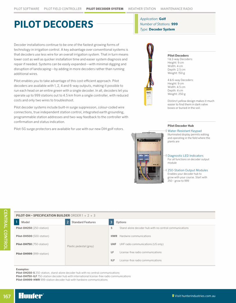
Pilot Decoders 1 & 2-way Decoders: Height: 9 cm Width: 4 cm Depth: 2.5 cm Weight: 150 g 4 & 6-way Decoders: Height: 9 cm Width: 4.5 cm Depth: 4 cm Weight: 250 g Distinct yellow design makes it much easier to find them in dark valve boxes or buried in the soil.
Pilot Decoder Hub
Decoder installations continue to be one of the fastest growing forms of
technology in irrigation control. A key advantage over conventional systems is
that decoders use less wire for an overall irrigation system. That in turn means
lower cost as well as quicker installation time and easier system diagnosis and
repair if needed. Systems can be easily expanded—with minimal digging and
disruption of landscaping—by adding in more decoders rather than running
additional wires.
Pilot enables you to take advantage of this cost-efficient approach. Pilot
decoders are available with 1, 2, 4 and 6-way outputs, making it possible to
run each head on an entire green with a single decoder. In all, decoders let you
operate up to 999 stations out to 4.5 km from a single controller, with reduced
costs and only two wires to troubleshoot.
Pilot decoder systems include built-in surge suppression, colour-coded wire
connections, true independent station control, integrated earth grounding,
programmable station addresses and two-way feedback to the controller with
confirmation and status indication.
Pilot-SG surge protectors are available for use with our new DIH golf rotors.
PILot DeCoDeRS Application: GolfNumber of Stations: 999 Type: Decoder System
PILOT SOFTWARE PILOT FIELD CONTROLLER pILot decoder system WEATHER STATION MAINTENANCE RADIO
Water-Resistant KeypadIlluminated display permits editing and operating in the field where the plants are
250-Station Output Modules Enables your decoder hub to grow with your course. Start with 250 - grow to 999
Diagnostic LED IndicatorsFor all functions on decoder output module
PILot-DH – SPeCIFICatIoN bUILDeR ORDER 1 + 2 + 3
1 model 2 standard Features 3 options
Pilot-DH250 (250-station) S Stand-alone decoder hub with no central communications
Pilot-DH500 (500-station) HwR Hardwire communications
Pilot-DH750 (750-station)Plastic pedestal (grey)
UHF UHF radio communications (US only)
Pilot-DH999 (999-station) LF License-free radio communications
ILF License-free radio communications
examples:Pilot-DH250-S 250-station, stand-alone decoder hub with no central communicationsPilot-DH750-ILF 750-station decoder hub with international license-free radio communicationsPilot-DH999-HwR 999-station decoder hub with hardwire communications
Cen
tRa
l C
on
tRo
l

168
CEN
TRA
L C
oN
TRo
L
Visit hunterindustries.com.au golf IrrIgatIon | Built on Innovation
Decoder-In-HeadHunter’s exclusive DIH golf rotor minimises valve box covers on playing surface
Extend control up to 4,5 km with a single pair of wires
Decoder in valve box Runs up to 45 m from decoder to solenoids
Expansion options If your course has over 999 stations you can use up to 999 decoder hubs for 998,001 decoders
PILOT SOFTWARE PILOT FIELD CONTROLLER pILot decoder system WEATHER STATION MAINTENANCE RADIO
DeCoDeRS – SPeCIFICatIoN bUILDeR ORDER 1 + 2
1 model 2 standard Features
Pilot-100 1-station decoder
Built-in surge protectionPilot-200 2-station decoder
Pilot-400 4-station decoder
Pilot-600 6-station decoder
Pilot-SG Inline surge protection
example:Pilot-100 1-station decoder
Pilot-DHprovides independent station control of 999 decoders with up to 120 running simultaneously
Cen
tRa
l C
on
tRo
l

169 Visit hunterindustries.com.au
CEN
TRA
L C
oN
TRo
L
FeatuRes• Includes built-in 60-day data logger: With onboard evapotranspiration (ET)
calculation (modified Penman-Monteith equation for turf grass)• Wireless package uses 2.4 GHz licence-free technology
- 2.4 GHz radio systems can reach up to 3 km - In rural areas, try the licence-free, 900 MHz radio for links up to 800 m
• Wired systems use Hunter GCBL, direct-bury cable with a range of 1.25 km (dedicated computer port required)
• Optional solar panel kit provides wireless power - For astonishing ease of installation and versatile mounting. On-board 800 mAh rechargeable gel cell battery with 18 VDC transformer and 7 m power cable
• Weatherproof construction: With UV stabilised enclosure, weather-proof external connectors and long-life coated circuit boards
• UL, c-UL and CE certifications• Warranty period: 1 year
turfweather Station Height: 61 cm Width: 40.5 cm Depth: 38 cm Weight: 6 kg
Application: GolfRange: wireless 1 kmType: weather Station
weatHeR StatIoN
CoMPLete PaCKaGeS INCLUDe HUNteR weatHeR SoFtwaRe
model description
tWHW Wired communications to central computer – GCBL cable is required
tW24 2.4 GHz licence-free radio communication to central computer
tW916 916 MHz licence-free radio communication to central computer
tW922a 922 MHz licence-free radio communication to central computer
tWsun Optional solar power kit for all TurfWeather models
PILOT SOFTWARE PILOT FIELD CONTROLLER PILOT DECODER SYSTEM Weather statIon MAINTENANCE RADIO
Cen
tRa
l C
on
tRo
l

170 Visit hunterindustries.com.au golf IrrIgatIon | Built on Innovation
CEn
tra
l
Co
ntr
ol
FeatuRes• Instant control of stations, blocks and programs• Fewer buttons to push• Instant audio confirmation of commands• Hunter’s famous StraightTalk™ Technology: Enables wireless
remote control at ranges up to 3.5 km whether or not the central computer is turned on
• Easy commands that show in display before sending• Compact size, industrial construction• Suitable for two-way voice communication with crews and office• High signal output: 2 watts, UHF (450–470 MHz)*
Note: *License required in most countries
tRNR Radio Height: 10.25 cm Width: 5.25 cm Depth: 3 cm Weight: 200 grams
Application: GolfRange: Up to 3.5 kmType: Remote Control
MaINteNaNCe RaDIo
PILOT SOFTWARE PILOT FIELD CONTROLLER PILOT DECODER SYSTEM WEATHER STATION maIntenance radIo
tRnR Radio
Cen
tRa
l C
on
tRo
l