2012/02/02 Areva EPR DC - DRAFT Response to U.S. EPR Design … · 2012-07-19 · Attached are...
82
1 ArevaEPRDCPEm Resource From: WILLIFORD Dennis (AREVA) [[email protected]] Sent: Thursday, February 02, 2012 9:48 AM To: Tesfaye, Getachew Cc: BENNETT Kathy (AREVA); CRIBB Arnie (EXTERNAL AREVA); DELANO Karen (AREVA); HATHCOCK Phillip (AREVA); ROMINE Judy (AREVA); RYAN Tom (AREVA); HUDSON Greg (AREVA); MEACHAM Robert (AREVA) Subject: DRAFT Response to U.S. EPR Design Certification Application RAI No. 506 (5456), FSAR Ch. 14, Questions 14.03.05-27, -30 and -41 Attachments: RAI 506 Response US EPR DC - DRAFT 3.pdf Getachew, Attached are DRAFT responses to Questions 14.03.05-27, 14.03.05-30 and 14.03.05-41 for RAI No. 506 (FSAR Ch. 14) in advance of the February 21, 2012 final date. Let me know if the staff has any questions or if this response can be sent as final. Thanks, Dennis Williford, P.E. U.S. EPR Design Certification Licensing Manager AREVA NP Inc. 7207 IBM Drive, Mail Code CLT 2B Charlotte, NC 28262 Phone: 704-805-2223 Email: [email protected] From: WILLIFORD Dennis (RS/NB) Sent: Thursday, January 19, 2012 10:48 AM To: [email protected] Cc: BENNETT Kathy (RS/NB); DELANO Karen (RS/NB); ROMINE Judy (RS/NB); RYAN Tom (RS/NB); LENTZ Tony (External RS/NB) Subject: Response to U.S. EPR Design Certification Application RAI No. 506 (5456), FSAR Ch. 14, Supplement 5 Getachew, AREVA NP Inc. provided a schedule for technically correct and complete responses to the 18 questions in RAI No. 506 on September 28, 2011. Supplement 1 response was submitted on November 8, 2011 to provide technically correct and complete responses to 12 of the 18 questions. Supplement 2 response was submitted on November 17, 2011 to provide a revised response to Question 14.03.05-29. Supplement 3 response was submitted on December 1, 2011 to provide a revised schedule for 3 questions. Supplement 4 response was submitted on January 13, 2012 to provide technically correct and complete responses to 2 questions. The schedule for a technically correct and complete final response to the remaining 4 questions has been changed as provided below. Question # Response Date RAI 506 — 14.03.05-27 February 21, 2012
Transcript of 2012/02/02 Areva EPR DC - DRAFT Response to U.S. EPR Design … · 2012-07-19 · Attached are...

1
ArevaEPRDCPEm Resource
From: WILLIFORD Dennis (AREVA) [[email protected]]Sent: Thursday, February 02, 2012 9:48 AMTo: Tesfaye, GetachewCc: BENNETT Kathy (AREVA); CRIBB Arnie (EXTERNAL AREVA); DELANO Karen (AREVA);
HATHCOCK Phillip (AREVA); ROMINE Judy (AREVA); RYAN Tom (AREVA); HUDSON Greg (AREVA); MEACHAM Robert (AREVA)
Subject: DRAFT Response to U.S. EPR Design Certification Application RAI No. 506 (5456), FSAR Ch. 14, Questions 14.03.05-27, -30 and -41
Attachments: RAI 506 Response US EPR DC - DRAFT 3.pdf
Getachew, Attached are DRAFT responses to Questions 14.03.05-27, 14.03.05-30 and 14.03.05-41 for RAI No. 506 (FSAR Ch. 14) in advance of the February 21, 2012 final date. Let me know if the staff has any questions or if this response can be sent as final. Thanks, Dennis Williford, P.E. U.S. EPR Design Certification Licensing Manager AREVA NP Inc. 7207 IBM Drive, Mail Code CLT 2B Charlotte, NC 28262 Phone: 704-805-2223 Email: [email protected]
From: WILLIFORD Dennis (RS/NB) Sent: Thursday, January 19, 2012 10:48 AM To: [email protected] Cc: BENNETT Kathy (RS/NB); DELANO Karen (RS/NB); ROMINE Judy (RS/NB); RYAN Tom (RS/NB); LENTZ Tony (External RS/NB) Subject: Response to U.S. EPR Design Certification Application RAI No. 506 (5456), FSAR Ch. 14, Supplement 5 Getachew, AREVA NP Inc. provided a schedule for technically correct and complete responses to the 18 questions in RAI No. 506 on September 28, 2011. Supplement 1 response was submitted on November 8, 2011 to provide technically correct and complete responses to 12 of the 18 questions. Supplement 2 response was submitted on November 17, 2011 to provide a revised response to Question 14.03.05-29. Supplement 3 response was submitted on December 1, 2011 to provide a revised schedule for 3 questions. Supplement 4 response was submitted on January 13, 2012 to provide technically correct and complete responses to 2 questions. The schedule for a technically correct and complete final response to the remaining 4 questions has been changed as provided below.
Question # Response Date
RAI 506 — 14.03.05-27 February 21, 2012

2
RAI 506 — 14.03.05-30 February 21, 2012
RAI 506 — 14.03.05-39 February 21, 2012
RAI 506 — 14.03.05-41 February 21, 2012
Sincerely, Dennis Williford, P.E. U.S. EPR Design Certification Licensing Manager AREVA NP Inc. 7207 IBM Drive, Mail Code CLT 2B Charlotte, NC 28262 Phone: 704-805-2223 Email: [email protected]
From: WILLIFORD Dennis (CORP/QP) Sent: Friday, January 13, 2012 12:39 PM To: [email protected] Cc: BENNETT Kathy (RS/NB); DELANO Karen (RS/NB); ROMINE Judy (RS/NB); RYAN Tom (RS/NB); LENTZ Tony (External RS/NB) Subject: Response to U.S. EPR Design Certification Application RAI No. 506 (5456), FSAR Ch. 14, Supplement 4 Getachew, AREVA NP Inc. provided a schedule for technically correct and complete responses to the 18 questions in RAI No. 506 on September 28, 2011. Supplement 1 response was submitted on November 8, 2011 to provide technically correct and complete responses to 12 of the 18 questions. Supplement 2 response was submitted on November 17, 2011 to provide a revised response to Question 14.03.05-29. Supplement 3 response was submitted on December 1, 2011 to provide a revised schedule for 3 questions. The attached file, “RAI 506 Supplement 4 Response US EPR DC.pdf” provides a technically correct and complete final response to 2 questions. Appended to this file are affected pages of the U.S. EPR Final Safety Analysis Report in redline-strikeout format which support the response to RAI 506 Questions 14.03.05-28 and 14.03.05-35. The following table indicates the respective pages in the response document, “RAI 506 Supplement 4 Response US EPR DC.pdf,” that contain AREVA NP’s response to the subject questions.
Question # Start Page End Page
RAI 506 — 14.03.05-28 2 3 RAI 506 — 14.03.05-35 4 4
The schedule for a technically correct and complete final response to the remaining 4 questions is unchanged as provided below.
Question # Response Date
RAI 506 — 14.03.05-27 January 19, 2012

3
RAI 506 — 14.03.05-30 January 19, 2012
RAI 506 — 14.03.05-39 January 19, 2012
RAI 506 — 14.03.05-41 January 19, 2012
Sincerely, Dennis Williford, P.E. U.S. EPR Design Certification Licensing Manager AREVA NP Inc. 7207 IBM Drive, Mail Code CLT 2B Charlotte, NC 28262 Phone: 704-805-2223 Email: [email protected]
From: WILLIFORD Dennis (RS/NB) Sent: Thursday, December 01, 2011 3:07 PM To: [email protected] Cc: BENNETT Kathy (RS/NB); DELANO Karen (RS/NB); ROMINE Judy (RS/NB); RYAN Tom (RS/NB); LENTZ Tony (External RS/NB) Subject: Response to U.S. EPR Design Certification Application RAI No. 506 (5456), FSAR Ch. 14, Supplement 3 Getachew, AREVA NP Inc. provided a schedule for technically correct and complete responses to the 18 questions in RAI No. 506 on September 28, 2011. Supplement 1 response was submitted on November 8, 2011 to provide technically correct and complete responses to 12 of the 18 questions. Supplement 2 response was submitted on November 17, 2011 to provide a revised response to Question 14.03.05-29. The schedule for providing a response to Questions 14.03.05-27, 14.03.05-28 and 14.03.05-35 has been revised as provided below. The schedule for a response to the other 3 questions remains unchanged.
Question # Response Date
RAI 506 — 14.03.05-27 January 19, 2012
RAI 506 — 14.03.05-28 January 19, 2012
RAI 506 — 14.03.05-30 January 19, 2012
RAI 506 — 14.03.05-35 January 19, 2012
RAI 506 — 14.03.05-39 January 19, 2012
RAI 506 — 14.03.05-41 January 19, 2012
Sincerely, Dennis Williford, P.E. U.S. EPR Design Certification Licensing Manager AREVA NP Inc. 7207 IBM Drive, Mail Code CLT 2B Charlotte, NC 28262

4
Phone: 704-805-2223 Email: [email protected]
From: WILLIFORD Dennis (RS/NB) Sent: Thursday, November 17, 2011 12:11 PM To: [email protected] Cc: BENNETT Kathy (RS/NB); DELANO Karen (RS/NB); ROMINE Judy (RS/NB); RYAN Tom (RS/NB); LENTZ Tony (External RS/NB) Subject: Response to U.S. EPR Design Certification Application RAI No. 506 (5456), FSAR Ch. 14, Supplement 2 Getachew, AREVA NP Inc. provided a schedule for technically correct and complete responses to the 18 questions in RAI No. 506 on September 28, 2011. Supplement 1 response to RAI 506 was submitted on November 8, 2011 to provide technically correct and complete responses to 12 of the 18 questions. The attached file, “RAI 506 Supplement 2 Response US EPR DC.pdf” provides a technically correct and complete revised final response to Question 14.03.05-29. The response has not changed from that provided in Supplement 1, however two additional affected pages from the U.S. EPR Final Safety Analysis Report were omitted from the earlier transmittal. Appended to this file are affected pages of the U.S. EPR Final Safety Analysis Report in redline-strikeout format which support the response to Question 14.03.05-29. The following table indicates the respective pages in the response document, “RAI 506 Supplement 2 Response US EPR DC.pdf,” that contain AREVA NP’s revised response to the subject question.
Question # Start Page End Page
RAI 506 — 14.03.05-29 2 2
The schedule for a technically correct and complete response to the remaining 6 questions is unchanged as provided below.
Question # Response Date
RAI 506 — 14.03.05-27 December 9, 2011
RAI 506 — 14.03.05-28 December 9, 2011
RAI 506 — 14.03.05-30 January 19, 2012
RAI 506 — 14.03.05-35 December 9, 2011
RAI 506 — 14.03.05-39 January 19, 2012
RAI 506 — 14.03.05-41 January 19, 2012
Sincerely, Dennis Williford, P.E. U.S. EPR Design Certification Licensing Manager AREVA NP Inc. 7207 IBM Drive, Mail Code CLT 2B

5
Charlotte, NC 28262 Phone: 704-805-2223 Email: [email protected]
From: WILLIFORD Dennis (RS/NB) Sent: Tuesday, November 08, 2011 4:24 PM To: [email protected] Cc: BENNETT Kathy (RS/NB); DELANO Karen (RS/NB); ROMINE Judy (RS/NB); RYAN Tom (RS/NB); LENTZ Tony (External RS/NB) Subject: Response to U.S. EPR Design Certification Application RAI No. 506 (5456), FSAR Ch. 14, Supplement 1 Getachew, AREVA NP Inc. provided a schedule for technically correct and complete responses to the 18 questions in RAI No. 506 on September 28, 2011. The attached file, “RAI 506 Supplement 1 Response US EPR DC.pdf” provides a technically correct and complete final response to 12 of the 18 questions. Appended to this file are affected pages of the U.S. EPR Final Safety Analysis Report in redline-strikeout format which support the response to Questions 14.03.05-25, 14.03.05-26, 14.03.05-29, 14.03.05-31, 14.03.05-32, 14.03.05-33, 14.03.05-34, 14.03.05-36, 14.03.05-37, 14.03.05-38, 14.03.05-40 and 14.03.05-42. The following table indicates the respective pages in the response document, “RAI 506 Supplement 1 Response US EPR DC.pdf,” that contain AREVA NP’s response to the subject questions.
Question # Start Page End Page
RAI 506 — 14.03.05-25 2 2
RAI 506 — 14.03.05-26 3 3
RAI 506 — 14.03.05-29 4 4
RAI 506 — 14.03.05-31 5 5
RAI 506 — 14.03.05-32 6 6
RAI 506 — 14.03.05-33 7 7
RAI 506 — 14.03.05-34 8 8
RAI 506 — 14.03.05-36 9 9
RAI 506 — 14.03.05-37 10 10
RAI 506 — 14.03.05-38 11 11
RAI 506 — 14.03.05-40 12 12
RAI 506 — 14.03.05-42 13 13
The schedule for a technically correct and complete response to the remaining 6 questions has been revised as provided below.
Question # Response Date
RAI 506 — 14.03.05-27 December 9, 2011
RAI 506 — 14.03.05-28 December 9, 2011
RAI 506 — 14.03.05-30 January 19, 2012

6
RAI 506 — 14.03.05-35 December 9, 2011
RAI 506 — 14.03.05-39 January 19, 2012
RAI 506 — 14.03.05-41 January 19, 2012
Sincerely, Dennis Williford, P.E. U.S. EPR Design Certification Licensing Manager AREVA NP Inc. 7207 IBM Drive, Mail Code CLT 2B Charlotte, NC 28262 Phone: 704-805-2223 Email: [email protected]
From: WILLIFORD Dennis (RS/NB) Sent: Wednesday, September 28, 2011 5:19 PM To: [email protected] Cc: BENNETT Kathy (RS/NB); DELANO Karen (RS/NB); ROMINE Judy (RS/NB); RYAN Tom (RS/NB); LENTZ Tony (External RS/NB) Subject: Response to U.S. EPR Design Certification Application RAI No. 506 (5456), FSAR Ch. 14 Getachew, Attached please find AREVA NP Inc.’s response to the subject request for additional information (RAI). The attached file, “RAI 506 Response US EPR DC.pdf,” provides a schedule since a technically correct and complete response to the 18 questions cannot be provided at this time. The following table indicates the respective pages in the response document, “RAI 506 Response US EPR DC.pdf,” that contain AREVA NP’s response to the subject questions.
Question # Start Page End Page
RAI 506 — 14.03.05-25 2 2
RAI 506 — 14.03.05-26 3 3
RAI 506 — 14.03.05-27 4 4
RAI 506 — 14.03.05-28 5 5
RAI 506 — 14.03.05-29 6 6
RAI 506 — 14.03.05-30 7 7
RAI 506 — 14.03.05-31 8 8
RAI 506 — 14.03.05-32 9 9
RAI 506 — 14.03.05-33 10 10
RAI 506 — 14.03.05-34 11 11
RAI 506 — 14.03.05-35 12 12
RAI 506 — 14.03.05-36 13 13
RAI 506 — 14.03.05-37 14 14
RAI 506 — 14.03.05-38 15 15
RAI 506 — 14.03.05-39 16 16
RAI 506 — 14.03.05-40 17 17

7
RAI 506 — 14.03.05-41 18 18
RAI 506 — 14.03.05-42 19 19
A complete answer is not provided for the 18 questions. The schedule for a technically correct and complete response to these questions is provided below.
Question # Response Date
RAI 506 — 14.03.05-25 November 8, 2011
RAI 506 — 14.03.05-26 November 8, 2011
RAI 506 — 14.03.05-27 November 8, 2011
RAI 506 — 14.03.05-28 November 8, 2011
RAI 506 — 14.03.05-29 November 8, 2011
RAI 506 — 14.03.05-30 November 8, 2011
RAI 506 — 14.03.05-31 November 8, 2011
RAI 506 — 14.03.05-32 November 8, 2011
RAI 506 — 14.03.05-33 November 8, 2011
RAI 506 — 14.03.05-34 November 8, 2011
RAI 506 — 14.03.05-35 November 8, 2011
RAI 506 — 14.03.05-36 November 8, 2011
RAI 506 — 14.03.05-37 November 8, 2011
RAI 506 — 14.03.05-38 November 8, 2011
RAI 506 — 14.03.05-39 November 8, 2011
RAI 506 — 14.03.05-40 November 8, 2011
RAI 506 — 14.03.05-41 November 8, 2011
RAI 506 — 14.03.05-42 November 8, 2011
Sincerely, Dennis Williford, P.E. U.S. EPR Design Certification Licensing Manager AREVA NP Inc. 7207 IBM Drive, Mail Code CLT 2B Charlotte, NC 28262 Phone: 704-805-2223 Email: [email protected]
From: Tesfaye, Getachew [mailto:[email protected]] Sent: Tuesday, August 30, 2011 1:31 PM To: ZZ-DL-A-USEPR-DL Cc: Mills, Daniel; Zhang, Deanna; Morton, Wendell; Spaulding, Deirdre; Mott, Kenneth; Truong, Tung; Zhao, Jack; Jackson, Terry; Jaffe, David; Canova, Michael; Colaccino, Joseph; ArevaEPRDCPEm Resource Subject: U.S. EPR Design Certification Application RAI No. 506 (5456), FSAR Ch. 14 Attached please find the subject requests for additional information (RAI). A draft of the RAI was provided to you on August 12, 2011, and discussed with your staff on August 25 and 29, 2011. Draft RAI Question

8
14.03.05-38 has been modified as a result of those discussions. The schedule we have established for review of your application assumes technically correct and complete responses within 30 days of receipt of RAIs. For any RAIs that cannot be answered within 30 days, it is expected that a date for receipt of this information will be provided to the staff within the 30 day period so that the staff can assess how this information will impact the published schedule.
Thanks, Getachew Tesfaye Sr. Project Manager NRO/DNRL/NARP (301) 415-3361

Hearing Identifier: AREVA_EPR_DC_RAIs Email Number: 3731 Mail Envelope Properties (2FBE1051AEB2E748A0F98DF9EEE5A5D4AA0A66) Subject: DRAFT Response to U.S. EPR Design Certification Application RAI No. 506 (5456), FSAR Ch. 14, Questions 14.03.05-27, -30 and -41 Sent Date: 2/2/2012 9:47:34 AM Received Date: 2/2/2012 9:47:54 AM From: WILLIFORD Dennis (AREVA) Created By: [email protected] Recipients: "BENNETT Kathy (AREVA)" <[email protected]> Tracking Status: None "CRIBB Arnie (EXTERNAL AREVA)" <[email protected]> Tracking Status: None "DELANO Karen (AREVA)" <[email protected]> Tracking Status: None "HATHCOCK Phillip (AREVA)" <[email protected]> Tracking Status: None "ROMINE Judy (AREVA)" <[email protected]> Tracking Status: None "RYAN Tom (AREVA)" <[email protected]> Tracking Status: None "HUDSON Greg (AREVA)" <[email protected]> Tracking Status: None "MEACHAM Robert (AREVA)" <[email protected]> Tracking Status: None "Tesfaye, Getachew" <[email protected]> Tracking Status: None Post Office: auscharmx02.adom.ad.corp Files Size Date & Time MESSAGE 14755 2/2/2012 9:47:54 AM RAI 506 Response US EPR DC - DRAFT 3.pdf 1540874 Options Priority: Standard Return Notification: No Reply Requested: No Sensitivity: Normal Expiration Date: Recipients Received:

Response to
Request for Additional Information No. 506(5456), Revision 0
8/30/2011
U. S. EPR Standard Design Certification AREVA NP Inc.
Docket No. 52-020 SRP Section: 14.03.05 - Instrumentation and Controls - Inspections, Tests,
Analyses, and Acceptance Criteria Application Section: 2.4
QUESTIONS for Instrumentation, Controls and Electrical Engineering 1 (AP1000/EPR Projects) (ICE1)
nd Electrical nd Eleccts) (ICE1) cts) (ICE1)

AREVA NP Inc.
Response to Request for Additional Information No. 506 – DRAFT3 U.S. EPR Design Certification Application Page 2 of 6
Question 14.03.05-27:
Provide a listing of the safety functions of the Safety Information and Control System (SICS) and clarify how the ITAAC map to those safety functions.
10 CFR 52.47(b)(1) requires inspections, tests, analyses, and acceptance criteria that are necessary and sufficient to provide reasonable assurance that, if the inspections, tests, and analyses are performed and the acceptance criteria met, a facility that incorporates the design certification has been constructed and will be operated in conformity with the design certification, the provisions of the Act, and the Commission's rules and regulations. U.S. EPR FSAR, Tier 1, Section 2.4.2, includes ITAAC entries for all listed design description of the SICS but the actual "safety functions" are not listed. Item 4.10 for SICS refers to safety functions, but these functions are not detailed in the Tier 1 information for this system. Provide a listing of the safety functions of the SICS and clarify how the ITAAC map to those safety functions.
Response to Question 14.03.05-27:
The safety-related functions of the SICS are identified in U.S. EPR FSAR Tier 2, Table 7.1-3. These functions are:
1. Manual reactor trip.
2. Manual engineered safety features actuation.
3. Control of safety-related systems to reach and maintain safe shutdown (such as manual grouped controls for safety automation system and manual component controls via the priority and actuation control system).
4. Indication of Type A, B, and C PAM variables (note that not all PAM Type B and C variables are safety-related)
These functions, along with associated ITAAC, will be added to U.S. EPR FSAR Tier 1, Section 2.4.2, as shown in the attached markups.
FSAR Impact:
U.S. EPR FSAR Tier 1, Section 2.4.2 will be revised as described in the response and indicated on the enclosed markup. DRAFT
hosehose
in U.S. EPR FSAR Tiein U.S. EPR FSA
ation. ation
reacch and maintain safh and maintain saation syststem and manuem and man
ystem). ystem).
d C PAM variables (notd C PAM variables (n
with associated ITAACwith associated ITe attached markups.e attached markups.
ction 2ction 2

AREVA NP Inc.
Response to Request for Additional Information No. 506 – DRAFT3 U.S. EPR Design Certification Application Page 3 of 6
Question 14.03.05-30:
Clarify how the ITAAC in Tier 1 Section 2.4.5 verify the listed safety functions of the Priority and Actuation Control System.
10 CFR 52.47(b)(1) requires inspections, tests, analyses, and acceptance criteria that are necessary and sufficient to provide reasonable assurance that, if the inspections, tests, and analyses are performed and the acceptance criteria met, a facility that incorporates the design certification has been constructed and will be operated in conformity with the design certification, the provisions of the Act, and the Commission's rules and regulations. Tier 1, Section 2.4.5, includes ITAAC entries for all listed design description of the PACS, but it is unclear whether the actual safety functions are verified by ITAAC. Specifically, how does the ITAAC verify that the PACS prioritizes actuation requests from I&C systems, performs essential equipment protection, performs drive actuation, and performs drive monitoring? If other ITAAC, including those of mechanical systems, are used to verify PACS safety functions, demonstrate how those ITAAC verify the safety functions of PACS.
Response to Question 14.03.05-30:
U.S. EPR FSAR Tier 1, Section 2.4.5, Item 4.1 states that the primary safety function of the priority and actuator control system (PACS) is to prioritize commands from the instrumentation and controls (I&C) systems so that the protection system (PS) and diverse actuation system (DAS) have the highest level of priority.
U.S. EPR FSAR Tier 1, Section 2.4.5 and Tier 2, Sections 7.1 and 7.8 will be revised to indicate that commands from the PS and DAS have the same priority over the other signals received by the PACS.
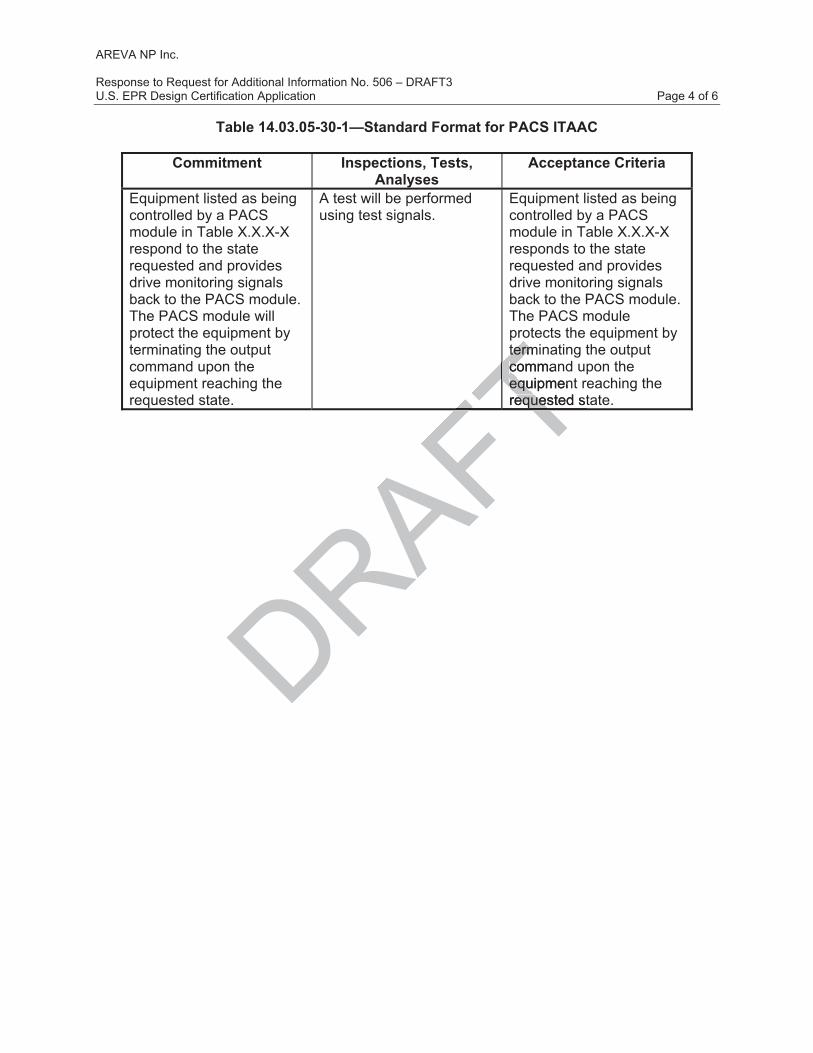
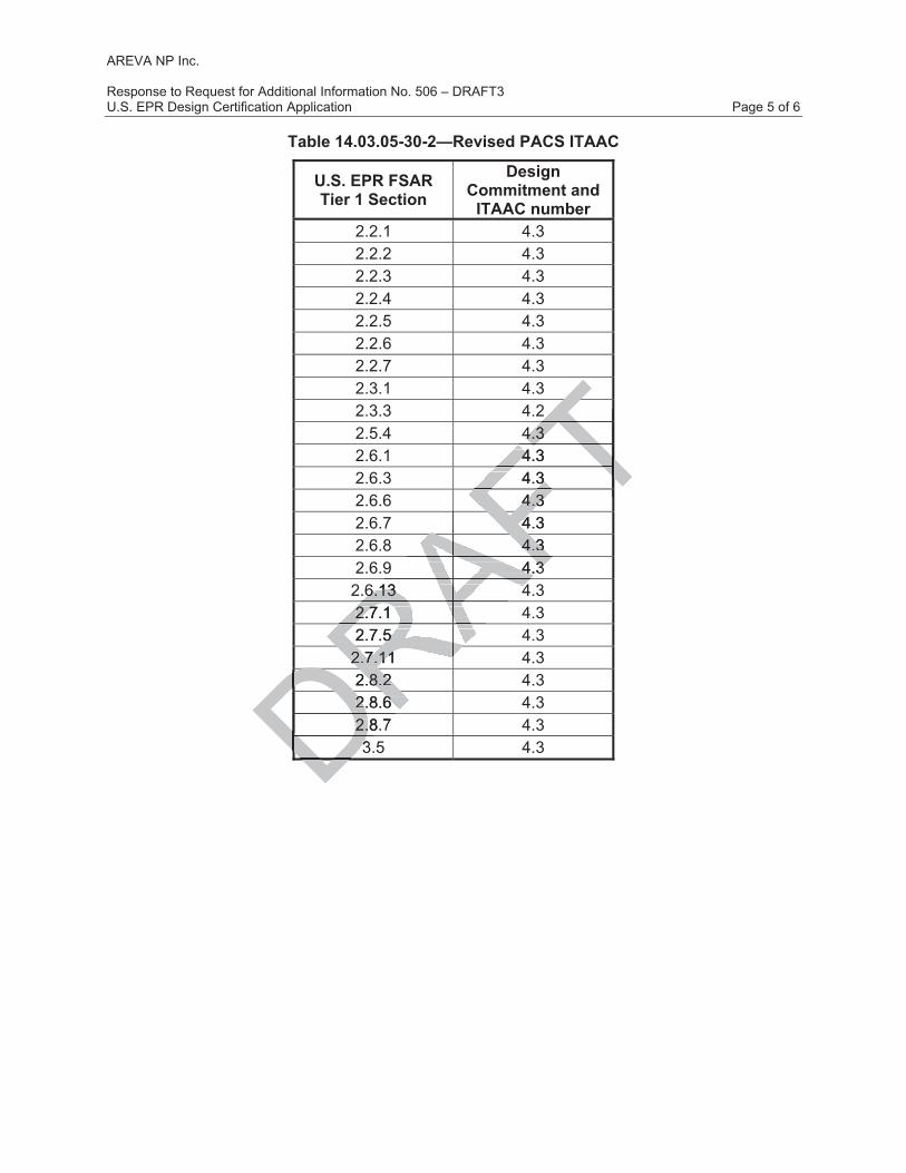
In addition to prioritizing actuation requests, U.S. EPR FSAR Tier 1, Section 2.4.5, Design Description states that the safety-related functions of the PACS are to perform essential equipment protection, drive actuation and drive monitoring. U.S. EPR FSAR Tier 1 will be revised to standardize design commitments and ITAAC to address the safety-related functions of PACS. The standard PACS ITAAC format is shown in Table 14.03.05-30-1, and the design commitments and ITAAC being revised are listed in Table 14.03.05-30-2.
FSAR Impact:
U.S. EPR FSAR Tier 1, Chapter 2 and Tier 2, Sections 7.1 and 7.8 will be revised as described in the response and indicated on the enclosed markup.
DRAFTve mve
CS safetyCS sa
ates that the primary sates that the to prioritize commandsoritize co
ection system (PS) and ection system (P
5 and Tier 2, Sections 5 and Tier 2, Sections DAS have the same DAS have the sa pri
ctuation requests, U.S.ctuation requests, U.S.the safety-related functthe safety-related
n, drive actuation and dn, drive actuation and ze design commitmeze design comm
d PACS ITAACd PACS ITAAbeing revibeing rev
AREVA NP Inc.
Response to Request for Additional Information No. 506 – DRAFT3 U.S. EPR Design Certification Application Page 4 of 6
Table 14.03.05-30-1—Standard Format for PACS ITAAC
Commitment Inspections, Tests, Analyses
Acceptance Criteria
Equipment listed as being controlled by a PACS module in Table X.X.X-X respond to the state requested and provides drive monitoring signals back to the PACS module. The PACS module will protect the equipment by terminating the output command upon the equipment reaching the requested state.
A test will be performed using test signals.
Equipment listed as being controlled by a PACS module in Table X.X.X-X responds to the state requested and provides drive monitoring signals back to the PACS module. The PACS module protects the equipment by terminating the output command upon the equipment reaching the requested state.
DRAFTtermitermcommacoequipmentequrequested steques
FTFTFT
AREVA NP Inc.
Response to Request for Additional Information No. 506 – DRAFT3 U.S. EPR Design Certification Application Page 5 of 6
Table 14.03.05-30-2—Revised PACS ITAAC
U.S. EPR FSAR Tier 1 Section
Design Commitment and
ITAAC number 2.2.1 4.3 2.2.2 4.3 2.2.3 4.3 2.2.4 4.3 2.2.5 4.3 2.2.6 4.3 2.2.7 4.3 2.3.1 4.3 2.3.3 4.2 2.5.4 4.3 2.6.1 4.3 2.6.3 4.3 2.6.6 4.3 2.6.7 4.3 2.6.8 4.3 2.6.9 4.3
2.6.13 4.3 2.7.1 4.3 2.7.5 4.3
2.7.11 4.3 2.8.2 4.3 2.8.6 4.3 2.8.7 4.3 3.5 4.3 DRA2.7.5 5 RAFTTT4.3 4.3 TT4.3 4 TT4.3 4.3 FTT4.3 4.3 FT
AT
4.3 4
AFA4.3 4.3 AFA9 4.3 4.3 AFRA6.13 46.13 4
RARA2.7.1 2.7.1
RARARARA2.7.11 2.7.11 RDR2.8.2 .8.2
DRD2.8.6 2.8.6 DRD2.8.72.DD33DDD
AREVA NP Inc.
Response to Request for Additional Information No. 506 – DRAFT3 U.S. EPR Design Certification Application Page 6 of 6
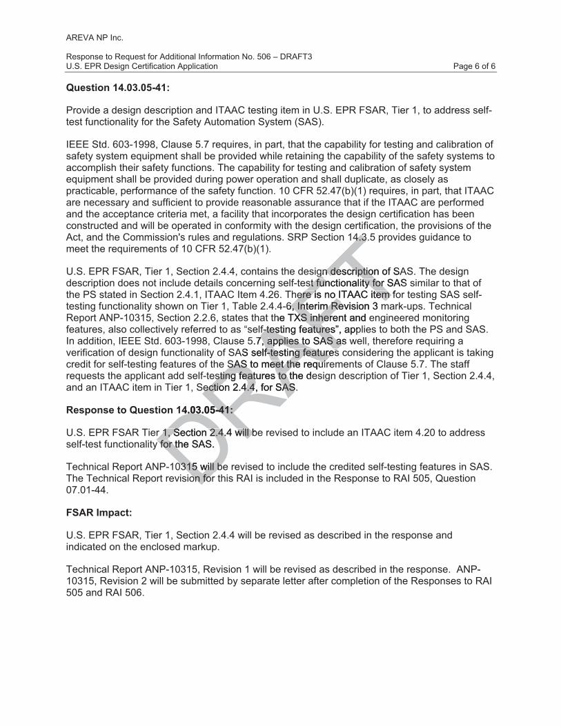
Question 14.03.05-41:
Provide a design description and ITAAC testing item in U.S. EPR FSAR, Tier 1, to address self-test functionality for the Safety Automation System (SAS).
IEEE Std. 603-1998, Clause 5.7 requires, in part, that the capability for testing and calibration of safety system equipment shall be provided while retaining the capability of the safety systems to accomplish their safety functions. The capability for testing and calibration of safety system equipment shall be provided during power operation and shall duplicate, as closely as practicable, performance of the safety function. 10 CFR 52.47(b)(1) requires, in part, that ITAAC are necessary and sufficient to provide reasonable assurance that if the ITAAC are performed and the acceptance criteria met, a facility that incorporates the design certification has been constructed and will be operated in conformity with the design certification, the provisions of the Act, and the Commission's rules and regulations. SRP Section 14.3.5 provides guidance to meet the requirements of 10 CFR 52.47(b)(1).
U.S. EPR FSAR, Tier 1, Section 2.4.4, contains the design description of SAS. The design description does not include details concerning self-test functionality for SAS similar to that of the PS stated in Section 2.4.1, ITAAC Item 4.26. There is no ITAAC item for testing SAS self-testing functionality shown on Tier 1, Table 2.4.4-6, Interim Revision 3 mark-ups. Technical Report ANP-10315, Section 2.2.6, states that the TXS inherent and engineered monitoring features, also collectively referred to as “self-testing features”, applies to both the PS and SAS. In addition, IEEE Std. 603-1998, Clause 5.7, applies to SAS as well, therefore requiring a verification of design functionality of SAS self-testing features considering the applicant is taking credit for self-testing features of the SAS to meet the requirements of Clause 5.7. The staff requests the applicant add self-testing features to the design description of Tier 1, Section 2.4.4, and an ITAAC item in Tier 1, Section 2.4.4, for SAS.
Response to Question 14.03.05-41:
U.S. EPR FSAR Tier 1, Section 2.4.4 will be revised to include an ITAAC item 4.20 to address self-test functionality for the SAS.
Technical Report ANP-10315 will be revised to include the credited self-testing features in SAS. The Technical Report revision for this RAI is included in the Response to RAI 505, Question 07.01-44.
FSAR Impact:
U.S. EPR FSAR, Tier 1, Section 2.4.4 will be revised as described in the response and indicated on the enclosed markup.
Technical Report ANP-10315, Revision 1 will be revised as described in the response. ANP-10315, Revision 2 will be submitted by separate letter after completion of the Responses to RAI 505 and RAI 506.
DRAFT4.3.4.3
gn description of SAgn descriptiost functionality for SASst functionality for
here is no ITAAC item fohere is no ITAAC item -6, Interim Revision 3 m6, Interim Re
the TXS inherent and eXS inherf-testing features”, appf-testing features
5.7, applies to SAS as w7, applies to SAS aAS self-testif-te ng featuresng features
SAS to meet the requirSAS to meet the requirsting features to the desting features to
ection 2.4.4, for SAS. ection 2.4.4, for SAS
4.03.05-41: 4.03.05-41:
r 1, Section 2.4.4 will ber 1, Section 2.4.4 will by for the SAS. y for th
0315 will be0315 will beon foron for

U.S. EPR Final Safety Analysis Report Markups
DRAFT

U.S. EPR FINAL SAFETY ANALYSIS REPORT
Tier 1 Revision 4—Interim Page 2.2-3
3.19 Each RCP contains an oil collection system.
3.20 RCS piping shown as ASME Code Section III on Figure 2.2.1-1 is designed in accordance with ASME Code Section III requirements.
3.21 RCS piping shown as ASME Code Section III on Figure 2.2.1-1 is installed reconciled in accordance with an ASME Code Section III Design Reportdesign requirements.
3.22 Pressure boundary welds in RCS piping shown as ASME Code Section III on Figure 2.2.1-1 are in accordance withmeet ASME Code Section III non-destructive examination requirements.
3.23 RCS piping shown as ASME Code Section III on Figure 2.2.1-1 retains pressure boundary integrity at design pressure.
3.24 RCS piping shown as ASME Code Section III on Figure 2.2.1-1 is fabricated, installed, and inspected in accordance with ASME Code Section III requirements.
3.25 Components listed in Table 2.2.1-1 as ASME Code Section III, other than RPV internals, are designed in accordance with ASME Code Section III requirements.
3.26 Components listed in Table 2.2.1-1 as ASME Code Section III, other than RPV internals, are fabricated reconciled in accordance with ASME Code Section III design requirements.
3.27 Pressure boundary welds on components listed in Table 2.2.1-1 as ASME Code Section III, other than RPV internals, are in accordance withmeet ASME Code Section III non-destructive examination requirements.
3.28 Components listed in Table 2.2.1-1 as ASME Code Section III, other than RPV internals, retain pressure boundary integrity at design pressure.
3.29 The RCP flywheel maintains its structural integrity during an overspeed event.
3.30 Components listed in Table 2.2.1-1 as ASME Code Section III are fabricated, installed, and inspected in accordance with ASME Code Section III requirements.
4.0 Instrumentation and Controls (I&C) Design Features, Displays, and Controls
4.1 Displays listed in Tables 2.2.1-2—Equipment and Valve Actuator Power Supplies and Controls and 2.2.1-3—Instrumentation Power Supplies, Classification, and Displays are retrievable indicated in the main control room (MCR) and remote shutdown station (RSS) as listed in Tables 2.2.1-2 and 2.2.1-3.
4.2 Controls on the PICS in the MCR and the RSS perform the function listed The RCS equipment controls are provided in the MCR and RSS as listed in Table 2.2.1-2.
4.3 Equipment listed as being controlled by a priority and actuator control system (PACS) module in Table 2.2.1-2 responds to the state requested by a test signal and provides drive monitoring signals back to the PACS module. The PACS module will protect the
14.03.05-30
DRAFTure 2.2ure 2
ction III requction I
E Code Section III, otheE Code Section IIode Section III requiremeode Section III require
as ASME Code Section IIASME Codedance with ASME Code th ASM
on components listed in ponents listed internals, ternals, are in accordancen acco
RAation ation
Rrequirements. uirements.
listed in Table 2.2.1-1 as d in Table 2.2.1-1 as sure boundary integrity atsure boundary in
RCP flywheel maintains iRCP flywheel maintains i
nts listed in Tants listed in Tdd in accor in accordd

U.S. EPR FINAL SAFETY ANALYSIS REPORT
Tier 1 Revision 4—Interim Page 2.2-4
equipment by terminating the output command upon the equipment reaching the requested state.
4.4 Instrumentation providing input to the uncertainty in power supports the power uncertainty assumed in the safety analysis.
5.0 Electrical Power Design Features
5.1 The components designated as Class 1E listed in Tables 2.2.1-2 and 2.2.1-3 are powered from the Class 1E divisions as listed in Tables 2.2.1-2 and 2.2.1-3 in a normal or alternate feed condition.
5.2 Deleted.
5.3 The power supply arrangement is such that only two emergency dieselsEDGs are required to operate to supply power to the minimum number of PZR heaters.
6.0 Environmental Qualifications
6.1 Components designated as harsh environment in Table 2.2.1-2, that are designated as harsh environment, will perform the function listed in Table 2.2.1-1 under normal environmental conditions, containment test conditions, anticipated operational occurrences, and accident and post-accident environmental conditions.in the environments that exist during and following design basis events.
6.2 Instrumentation in designated as harsh environment in Table 2.2.1-3, that are designated as harsh environment, will display as listed in Table 2.2.1-3 under normal environmental conditions, containment test conditions, anticipated operational occurrences, and accident and post-accident environmental conditions.in the environments that exist during and following design basis events.
7.0 Equipment and System Performance
7.1 Class 1E valves listed in Table 2.2.1-2 can perform the will function to change position as listed in Table 2.2.1-1 under system operating conditions.
7.2 The RCPs have rotational inertia to provide coastdown flow of reactor coolant as listed in Table 2.2.1-4 on loss of power to the pump motors.
7.3 The RCPs provide flow.
7.4 RCP standstill seal system (SSSS) can be engaged when the RCP is stopped.
7.5 The PZR safety relief valves (PSRVs) open.
7.6 The PSRVs listed in Table 2.2.1-2 open below the maximum setpoint assumed in the safety analyses.
7.7 The PSRVs provide relief capacity.
7.8 Each RCP supply circuit breaker and switchgear feeder circuit RCP bus breaker is tripped by a protection system signal.
14.03.05-30
DRAFTnumbernumb
ment ment
Fin Table 2.2.1-2in Table 2.2.1-2,,TthatTnction listed in Table 2.2.nction listed in Table 2.2.
ent test conditions, anticiptest conditio
AFTst-accident environmentant env
AFand following design basand following desig
AFnated as harsh environmenharsh environme
RAwill display as listed in Twill display as listment test conditions, antiment test conditions,
RAnt environmental conditiot environmental conditiRAign basis events.asis events.
DRment and System Perfment and System P
E valves listed in TaE valves listed inn Table 2.2.1-1n Table 2.2.1-
rotrot

U.S. EPR FINAL SAFETY ANALYSIS REPORT
Tier 1 Revision 4—Interim Page 2.2-36
Table 2.2.1-5—Reactor Coolant System ITAAC (11 Sheets)
Commitment Wording Inspections, Tests,
Analyses Acceptance Criteria 4.1 Displays listed in Tables
2.2.1-2 and 2.2.1-3 are retrievable indicated in the MCR and RSS as listed in Tables 2.2.1-2 and 2.2.1-3.
a. Tests will be performed in the MCR using test signals.
Tests will be performed for the retrievability of the displays in the MCR or the RSS as listed in Tables 2.2.1-2 and 2.2.1-3.
a. The dDisplays listed in Tables 2.2.1-2 and 2.2.1-3 are indicated as being retrievable in the MCR can be retrieved in the MCR.
b. Tests will be performed in the RSS using test signals.
b. The dDisplays listed in Tables 2.2.1-2 and 2.2.1-3 are indicated as being retrievable in the RSS can be retrieved in the RSS.
a. Tests will be performed using controls on the PICS in the MCR.
a. The Controls listed on the PICS in the MCR perform the function listed in Table 2.2.1-2 as being in the MCR exist in the MCR.
4.2 Controls on the PICS in the MCR and the RSS perform the function listedThe RCS equipment controls are provided in the MCR and RSS as identified in Table 2.2.1-2. b. Tests will be performed
using controls on the PICS in the RSS.Tests will be performed for the existence of control signals from the MCR and the RSS to the equipment listed in Table 2.2.1-2.
b. The cControls on the PICS in the RSS perform the function listed in Table 2.2.1-2 as being in the RSS exist in the RSS.
4.3 Equipment listed as being controlled by a PACS module in Table 2.2.1-2 responds to the state requested by a test signal and provides drive monitoring signals back to the PACS module. The PACS module will protect the equipment by terminating the output command upon the equipment reaching the requested state.
A test will be performed using test signals.
Equipment listed as being controlled by a PACS module in Table 2.2.1-2 responds to the state requested by the test signal and provides drive monitoring signals back to the PACS module. The PACS module will protect the equipment by terminating the output command upon the equipment reaching the requested state.
14.03.05-30
Ded as being ed as ACS ACS
1-2 1-2 DDRAFTRthe Tperformed perfo
FTrols on the PICS rols on the PFTMCR.CR.
AFa. a. The TththFTT
b. Tests will be performb. Tests will be perform
RAusing controls on using contr
RAin the RSS.in the RSSRATesAperformed fperformed RAof controf controRMCR RequeRDRDDD

U.S. EPR FINAL SAFETY ANALYSIS REPORT
Tier 1 Revision 4—Interim Page 2.2-47
3.9 IRWSTS piping shown as ASME Code Section III on Figure 2.2.2-1 is installed reconciled in accordance with an ASME Code Section III Design Reportdesign requirements.
3.10 Pressure boundary welds in IRWSTS piping shown as ASME Code Section III on Figure 2.2.2-1 are in accordance withmeet ASME Code Section III non-destructive examination requirements.
3.11 IRWSTS piping shown as ASME Code Section III on Figure 2.2.2-1 retains pressure boundary integrity at design pressure.
3.12 IRWSTS piping shown as ASME Code Section III on Figure 2.2.2-1 is fabricated, installed, and inspected in accordance with ASME Code Section III requirements.
3.13 Components listed in Table 2.2.2-1 as ASME Code Section III are designed in accordance with ASME Code Section III requirements.
3.14 Components listed in Table 2.2.2-1 as ASME Code Section III are fabricated reconciled in accordance with ASME Code Section III design requirements.
3.15 Pressure boundary welds on components listed in Table 2.2.2-1 as ASME Code Section III are in accordance withmeet ASME Code Section III non-destructive examination requirements.
3.16 Components listed in Table 2.2.2-1 as ASME Code Section III retain pressure boundary integrity at design pressure.
3.17 Components listed in Table 2.2.2-1 as ASME Code Section III are fabricated, installed, and inspected in accordance with ASME Code Section III requirements.
3.18 Containment isolation valves are located close to containment penetrations.
4.0 Instrumentation and Controls (I&C) Design Features, Displays, and Controls
4.1 Displays listed in Table 2.2.2-2—IRWSTS Equipment I&C and Electrical Design are retrievable indicated in the main control room (MCR) and the remote shutdown station (RSS) as listed in Table 2.2.2-2.
4.2 The IRWSTS equipment Controls on the PICS in the MCR and the RSS perform the function controls are provided in the MCR and the RSS as listed in Table 2.2.2-2.
4.3 Equipment listed as being controlled by a priority and actuator control system (PACS) module in Table 2.2.2-2 responds to the state requested by a test signal and provides drive monitoring signals back to the PACS module. The PACS module will protect the equipment by terminating the output command upon the equipment reaching the requested state.
4.4 Deleted.IRWST has level indication.
14.03.05-30
DRAFTtiotio
ts. ts.
Code Section III areode Sectiondesign design
FTrequirements. ireme
ts listed in Table 2.2.2-1 ts listed in Table 2.2.2-1 E Code Section III Code Sectio non-dF2.2.2-1 as ASME Code S2-1 as ASME Code
ure.
in Table 2.2.2-1 as ASMEin Table 2.2.2-1 as Aaccordance with ASME accordance with ASME
nt isolation valves are locnt isolation valv
DRumentation and Contumentation and Contols ols
ed in Tabed in Tabcatecate

U.S. EPR FINAL SAFETY ANALYSIS REPORT
Tier 1 Revision 4—Interim Page 2.2-61
Table 2.2.2-3—In-Containment Refueling Water Storage Tank System ITAAC (9 Sheets)
Commitment Wording Inspections, Tests, Analyses
Acceptance Criteria
2.2.2-2. b. Tests will be performed using controls on the PICS in the RSS.Tests will be performed for the existence of control signals from the MCR and the RSS to the equipment listed in Table 2.2.2-2.
b. The cControls on the PICS in the RSS perform the function listed in Table 2.2.2-2 as being in the RSS exist in the RSS.
4.3 Equipment listed as being controlled by a PACS module in Table 2.2.2-2 responds to the state requested by a test signal and provides drive monitoring signals back to the PACS module. The PACS module will protect the equipment by terminating the output command upon the equipment reaching the requested state.
A test will be performed using test signals.
Equipment listed as being controlled by a PACS module in Table 2.2.2-2 responds to the state requested by the signal and provides drive monitoring signals back to the PACS module. The PACS module will protect the equipment by terminating the output command upon the equipment reaching the requested state.
4.4 Deleted.IRWST has level indication.
Deleted.A test will be performed.
Deleted.a. IRWST level instruments included in Table 2.2.2-2 provide level indication in the MCR.
b. IRWST level instruments included in Table 2.2.2-2 provide level indication in the RSS.
5.1 The components designated as Class 1E in Table 2.2.2-2 are powered from the Class 1E division as listed in Table 2.2.2-2 in a normal or alternate feed condition.
a. Testing will be performed for components designated as Class 1E in Table 2.2.2-2 by providing a test signal in each normally aligned division.
a. The test signal provided in the normally aligned division is present at the respective Class 1E components identified in Table 2.2.2-2.
14.03.05-30
DRs level s level
DRDRDeleted.De
DRA teRDRAFTTng ng EquE
controin Table 2inthe state rethe ssignalgnal
FT an aTmonititFTPAFTTT
DRFTT
performedperfor
DRDRDRDRDRDRAFT

U.S. EPR FINAL SAFETY ANALYSIS REPORT
Tier 1 Revision 4—Interim Page 2.2-67
3.9 Deleted.
3.10 SIS/RHRS piping shown as ASME Code Section III on Figure 2.2.3-1 is designed in accordance with ASME Code Section III requirements.
3.11 SIS/RHRS piping shown as ASME Code Section III on Figure 2.2.3-1 is installed reconciled in accordance with an ASME Code Section III Design Reportdesign requirements.
3.12 Pressure boundary welds in SIS/RHRS piping shown as ASME Code Section III on Figure 2.2.3-1 are in accordance withmeet ASME Code Section III non-destructive examination requirements.
3.13 SIS/RHRS piping shown as ASME Code Section III on Figure 2.2.3-1 retains pressure boundary integrity at design pressure.
3.14 SIS/RHRS piping shown as ASME Code Section III on Figure 2.2.3-1 is fabricated, installed, and inspected in accordance with ASME Code Section III requirements.
3.15 Components listed in Table 2.2.3-1 as ASME Code Section III are designed in accordance with ASME Code Section III requirements.
3.16 Components listed in Table 2.2.3-1 as ASME Code Section III are fabricated reconciled in accordance with ASME Code Section III design requirements.
3.17 Pressure boundary welds on components listed in Table 2.2.3-1 as ASME Code Section III are in accordance withmeet ASME Code Section III non-destructive examination requirements.
3.18 Components listed in Table 2.2.3-1 as ASME Code Section III retain pressure boundary integrity at design pressure.
3.19 Components listed in Table 2.2.3-1 as ASME Code Section III are fabricated, installed, and inspected in accordance with ASME Code Section III requirements.
3.20 Containment isolation valves are located close to containment penetrations.
4.0 Instrumentation and Controls (I&C) Design Features, Displays, and Controls
4.1 Displays listed in Table 2.2.3-2—SIS/RHRS Equipment I&C and Electrical Design are retrievable indicated in the main control room (MCR) and the remote shutdown station (RSS) as listed in Table 2.2.3-2.
4.2 Controls on the PICS in the MCR and the RSS perform the function The SIS/RHRS equipment controls are provided in the MCR and the RSS as listed in Table 2.2.3-2.
4.3 Equipment listed as being controlled by a priority and actuator control system (PACS) module in Table 2.2.3-2 responds to the state requested by a test signal and provides drive monitoring signals back to the PACS module. The PACS module will protect the
14.03.05-30
DDRAFTIII on Figure III on
ME Code Section IME Code S
ME Code Section III are ME Code Section III aIII requirements. III requiremen
-1 as ASME Code SectionME Code Section III e Sectio design design
AFrequ
on components listed in ponents listed inwithwith
Rmeetmee
RA ASME Code SeME Ct
listed in Table 2.2.3-1 as d in Table 2.2.3-1 as t design pressure. design pressure
ponents listed in Table 2.ponents listed in Table 2.pectedpected D in accordancerdad
t isolationt isolationD

U.S. EPR FINAL SAFETY ANALYSIS REPORT
Tier 1 Revision 4—Interim Page 2.2-68
equipment by terminating the output command upon the equipment reaching the requested state.
4.4 The Interlocks for the SIS/RHRS has initiate the following system interlocks:
• Opening of the accumulator injection path.
• Opening authorization of the residual heat removal system suction path from the reactor coolant system.
• Opening authorization of the hot-leg safety injection path.
5.0 Electrical Power Design Features
5.1 The components designated as Class 1E in Table 2.2.3-2 are powered from the Class 1E division as listed in Table 2.2.3-2 in a normal or alternate feed condition.
5.2 Deleted.
6.0 Environmental Qualifications
6.1 Components designated as harsh environment in Table 2.2.3-2, that are designated as harsh environment, will perform the function listed in Table 2.2.3-1 under normal environmental conditions, containment test conditions, anticipated operational occurrences, and accident and post-accident environmental conditions.in the environments that exist during and following design basis events.
7.0 Equipment and System Performance
7.1 The SIS/RHRS heat exchangers listed in Table 2.2.3-1 have the capacity to transfer the design heat load to the component cooling water system.
7.2 The accumulators listed in Table 2.2.3-1 provide a required storage volume.
7.3 Each accumulator line has a minimum head loss coefficient (fL/D + K).
7.4 The pumps listed in Table 2.2.3-1 have net positive suction head available (NPSHA) that is greater than net positive suction head required (NPSHR) at system run-out flow.
7.5 The SIS/RHRS delivers water to the reactor coolant system for core cooling.
7.6 Deleted.The SIS/RHRS delivers water to the reactor coolant system within the system run-out flow rate and pump shutoff head for core cooling due to design basis events.
7.7 Class 1E valves listed in Table 2.2.3-2 can perform the will function to change position as listed in Table 2.2.3-1 under system operating conditions.
7.8 The SIS/RHRS provides for flow testing of the SIS/RHRS pumps during plant operation.
7.9 Safety injection pumped flow will be delivered to the RCS before the maximum elapsed time.
14.03.05-30
DRAFT2 a2 a
nate fenate
vironmentnment
AF in Table 2.2.3-in Ttthe function listed in Tabon lis
tainment test conditions, ainment test conditio
AFnd post-accident environmost-accident environAduring and following desid following desi
RASystem Performance System Performan
RS heat exchangers listed at exchangers listed t load to the component ct load to the com
ccumulators listed in Tabccumulators listed in Tab
mulator line hmulator line h
ed ined in
U.S. EPR FINAL SAFETY ANALYSIS REPORT
Tier 1 Revision 4—Interim Page 2.2-96
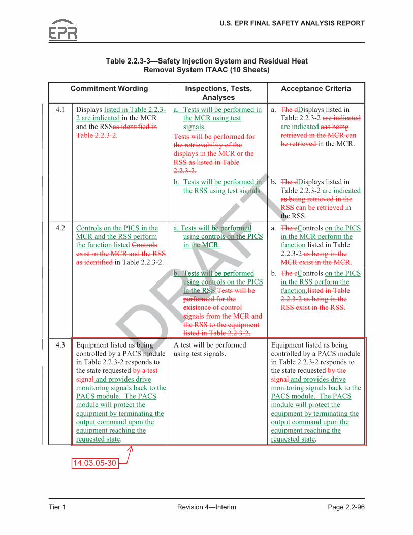
Table 2.2.3-3—Safety Injection System and Residual Heat Removal System ITAAC (10 Sheets)
Commitment Wording Inspections, Tests, Analyses
Acceptance Criteria
4.1 Displays listed in Table 2.2.3-2 are indicated in the MCR and the RSSas identified in Table 2.2.3-2.
a. Tests will be performed in the MCR using test signals.
Tests will be performed for the retrievability of the displays in the MCR or the RSS as listed in Table 2.2.3-2.
a. The dDisplays listed in Table 2.2.3-2 are indicated are indicated aas being retrieved in the MCR can be retrieved in the MCR.
b. Tests will be performed in the RSS using test signals.
b. The dDisplays listed in Table 2.2.3-2 are indicated as being retrieved in the RSS can be retrieved in the RSS.
4.2 Controls on the PICS in the MCR and the RSS perform the function listed Controls exist in the MCR and the RSS as identified in Table 2.2.3-2.
a. Tests will be performed using controls on the PICS in the MCR.
a. The cControls on the PICS in the MCR perform the function listed in Table 2.2.3-2 as being in the MCR exist in the MCR.
b. Tests will be performed using controls on the PICS in the RSS.Tests will be performed for the existence of control signals from the MCR and the RSS to the equipment listed in Table 2.2.3-2.
b. The cControls on the PICS in the RSS perform the function.listed in Table 2.2.3-2 as being in the RSS exist in the RSS.
4.3 Equipment listed as being controlled by a PACS module in Table 2.2.3-2 responds to the state requested by a test signal and provides drive monitoring signals back to the PACS module. The PACS module will protect the equipment by terminating the output command upon the equipment reaching the requested state.
A test will be performed using test signals.
Equipment listed as being controlled by a PACS module in Table 2.2.3-2 responds to the state requested by the signal and provides drive monitoring signals back to the PACS module. The PACS module will protect the equipment by terminating the output command upon the equipment reaching the requested state.
14.03.05-30
DRAFTTd in d in
Tgnals.gnals. Tb.
Taas beTRSS cTthe Rthe
FTll be performed be performed
AFTg controls on the PICS ls on th
AFthe MCR.the M
AFa. FTFTFTFTb. Tests will be perfb. Tests will b
RAusing controls using contrRAin the RSS.in the RSS.RATperformeerformeRexistenRsignsiRDR
s being s being modmodDD

U.S. EPR FINAL SAFETY ANALYSIS REPORT
Tier 1 Revision 4—Interim Page 2.2-102
3.9 EFWS piping shown as ASME Code Section III on Figure 2.2.4-1 is designed in accordance with ASME Code Section III requirements.
3.10 EFWS piping shown as ASME Code Section III on Figure 2.2.4-1 is installed reconciled in accordance with an ASME Code Section III Design Reportdesign requirements.
3.11 Pressure boundary welds in EFWS piping shown as ASME Code Section III on Figure 2.2.4-1 are in accordance withmeet ASME Code Section III non-destructive examination requirements.
3.12 EFWS piping shown as ASME Code Section III on Figure 2.2.4-1 retains pressure boundary integrity at design pressure.
3.13 EFWS piping shown as ASME Code Section III on Figure 2.2.4-1 is fabricated, installed, and inspected in accordance with ASME Code Section III requirements.
3.14 Components listed in Table 2.2.4-1 as ASME Code Section III are designed in accordance with ASME Code Section III requirements.
3.15 Components listed in Table 2.2.4-1 as ASME Code Section III are fabricated reconciled in accordance with ASME Code Section III design requirements.
3.16 Pressure boundary welds on components listed in Table 2.2.4-1 as ASME Code Section III are in accordance withmeet ASME Code Section III non-destructive examination requirements.
3.17 Components listed in Table 2.2.4-1 as ASME Code Section III retain pressure boundary integrity at design pressure.
3.18 Components listed in Table 2.2.4-1 as ASME Code Section III are fabricated, installed, and inspected in accordance with ASME Code Section III requirements.
3.19 Containment isolation valves are located close to containment penetrations.
4.0 Instrumentation and Controls (I&C) Design Features, Displays, and Controls
4.1 Displays listed in Table 2.2.4-2—EFWS Equipment I&C and Electrical Design are retrievable indicated in the main control room (MCR) and the remote shutdown station (RSS) as listed in Table 2.2.4-2.
4.2 Controls on the PICS in the MCR and the RSS perform the function The EFWS equipment controls are provided in the MCR and the RSS as listed in Table 2.2.4-2.
4.3 Equipment listed as being controlled by a priority and actuator control system (PACS) module in Table 2.2.4-2 responds to the state requested by a test signal and provides drive monitoring signals back to the PACS module. The PACS module will protect the equipment by terminating the output command upon the equipment reaching the requested state.
14.03.05-30
DRAFTIIIIII
e Section III e Secrements. ements.
ME Code Section III are ME Code Section III an III n III design gn FTrequirementsrequirements
ponents listed in Table 2.2isted iASME Code Section III ASME Code Sectio
Table 2.2.4-1 as ASME CTable 2.2.4-1 as Apressure. pressu
listed in Table 2.2.4-1 as d in Table 2.2.4-1 as tedted
D in accordance with A in accordancdd
inment isolation valves ainment isolation valves aDentation and entation and
U.S. EPR FINAL SAFETY ANALYSIS REPORT
Tier 1 Revision 4—Interim Page 2.2-115
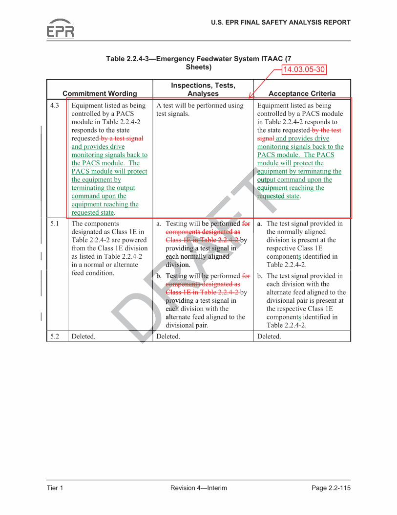
Table 2.2.4-3—Emergency Feedwater System ITAAC (7 Sheets)
Commitment Wording Inspections, Tests,
Analyses Acceptance Criteria 4.3 Equipment listed as being
controlled by a PACS module in Table 2.2.4-2 responds to the state requested by a test signal and provides drive monitoring signals back to the PACS module. The PACS module will protect the equipment by terminating the output command upon the equipment reaching the requested state.
A test will be performed using test signals.
Equipment listed as being controlled by a PACS module in Table 2.2.4-2 responds to the state requested by the test signal and provides drive monitoring signals back to the PACS module. The PACS module will protect the equipment by terminating the output command upon the equipment reaching the requested state.
a. Testing will be performed for components designated as Class 1E in Table 2.2.4-2 by providing a test signal in each normally aligned division.
a. The test signal provided in the normally aligned division is present at the respective Class 1E components identified in Table 2.2.4-2.
5.1 The components designated as Class 1E in Table 2.2.4-2 are powered from the Class 1E division as listed in Table 2.2.4-2 in a normal or alternate feed condition. b. Testing will be performed for
components designated as Class 1E in Table 2.2.4-2 by providing a test signal in each division with the alternate feed aligned to the divisional pair.
b. The test signal provided in each division with the alternate feed aligned to the divisional pair is present at the respective Class 1E components identified in Table 2.2.4-2.
5.2 Deleted. Deleted. Deleted.
14.03.05-30
DRAFTeqe
Toutpu
TequipmeeTrequested srequ
FTFTill be performed performe for FTnents designated as nents designated
AFs 1E in Table 2.2.41E in Table 2.2.4AF--AF2 2 Fby roviding a test signal in ng a test signal in
each normally aligned each normally aligned division. divisi
a. FTR
FTb. Testing will be pb. Testing will be
components dcomponents dRClass 1E inC
DRprovidinproveach ach altRDRDDD
FT

U.S. EPR FINAL SAFETY ANALYSIS REPORT
Tier 1 Revision 4—Interim Page 2.2-121
3.6 Deleted.
3.7 Deleted.
3.8 Deleted.
3.9 FPCPS piping shown as ASME Code Section III on Figure 2.2.5-1 is designed in accordance with ASME Code Section III requirements.
3.10 FPCPS piping shown as ASME Code Section III on Figure 2.2.5-1 is installed reconciled in accordance with an ASME Code Section III Design Reportdesign requirements.
3.11 Pressure boundary welds in FPCPS piping shown as ASME Code Section III on Figure 2.2.5-1 are in accordance withmeet ASME Code Section III non-destructive examination requirements.
3.12 FPCPS piping shown as ASME Code Section III on Figure 2.2.5-1 retains pressure boundary integrity at design pressure.
3.13 FPCPS piping shown as ASME Code Section III on Figure 2.2.5-1 is fabricated, installed, and inspected in accordance with ASME Code Section III requirements.
3.14 Components listed in Table 2.2.5-1 as ASME Code Section III are designed in accordance with ASME Code Section III requirements.
3.15 Components listed in Table 2.2.5-1 as ASME Code Section III are fabricated reconciled in accordance with ASME Code Section III design requirements.
3.16 Pressure boundary welds on components listed in Table 2.2.5-1 as ASME Code Section III are in accordance withmeet ASME Code Section III non-destructive examination requirements.
3.17 Components listed in Table 2.2.5-1 as ASME Code Section III retain pressure boundary integrity at design pressure.
3.18 Components listed in Table 2.2.5-1 as ASME Code Section III are fabricated, installed, and inspected in accordance with ASME Code Section III requirements.
3.19 Containment isolation valves are located close to containment penetrations.
4.0 Instrumentation and Controls (I&C) Design Features, Displays, and Controls
4.1 Displays listed in Table 2.2.5-2—FPCPS Equipment I&C and Electrical Design are retrievable indicated in the main control room (MCR) and the remote shutdown station (RSS) as listed in Table 2.2.5-2.
4.2 Controls on the PICS in the MCR and the RSS perform the functionThe FPCPS equipment controls are provided in the MCR and the RSS as listed in Table 2.2.5-2.
4.3 Equipment listed as being controlled by a priority and actuator control system (PACS) module in Table 2.2.5-2 responds to the state requested by a test signal and provides
14.03.05-30
DRAFTn Figure 2.2n Fig
tion III on Figure 2.2.5-1 tion III on Figure 2.2.5with ASME Code Sectionwith ASME Code Section
-1 as ASME Code SectionME CoSection III requirements. ection III requirem
ble 2.2.5-1 as ASME Cod-1 as ASME CoME Code Section III ME Code Section desAry welds on components y welds on components
rdance withce with
DRmeetmeet
DR ASME ASME ttnts. nts.
ponents listed in Table 2.2ponents listed in Table 2.ty at design pressure.ty at design press
listed in listed in n acn ac

U.S. EPR FINAL SAFETY ANALYSIS REPORT
Tier 1 Revision 4—Interim Page 2.2-122
drive monitoring signals back to the PACS module. The PACS module will protect the equipment by terminating the output command upon the equipment reaching the requested state.
5.0 Electrical Power Design Features
5.1 The components designated as Class 1E in Table 2.2.5-2 are powered from the Class 1E division as listed in Table 2.2.5-2 in a normal or alternate feed condition.
5.2 Deleted.
6.0 Environmental Qualifications
6.1 Components designated as harsh environment in Table 2.2.5-2, that are designated as harsh environment, will perform the function listed in Table 2.2.5-1 under normal environmental conditions, containment test conditions, anticipated operational occurrences, and accident and post-accident environmental conditions.in the environments that exist during and following design basis events.
7.0 Equipment and System Performance
7.1 The fuel pool cooling system heat exchangers listed in Table 2.2.5-1 each have the capacity to transfer the design heat load to the component cooling water system.
7.2 The pumps listed in Table 2.2.5-1 have net positive suction head available (NPSHA) that is greater than net positive suction head required (NPSHR) at system run-out flow.
7.3 Class 1E valves listed in Table 2.2.5-2 can perform the will function to change position as listed in Table 2.2.5-1 under system operating conditions.
7.4 The pumps listed in Table 2.2.5-1 each have the capacity to provide flow to the FPCS heat exchangers.
7.5 Containment isolation valves listed in Table 2.2.5-1 close within the containment isolation response time following initiation of a containment isolation signal.
7.6 The FPCS design provides for maintaining the spent fuel pool water level above the spent fuel.
8.0 Inspections, Tests, Analyses, and Acceptance Criteria
Table 2.2.5-3 lists the FPCPS ITAAC.
14.03.05-30
DRAFTs, antics, ant
Tonmental cononmen
Tesign basis events.esign basis Tce ce
xchangers listed in Table angers listedat load to the component the co
.2.5-1 have net positive s-1 have net positive ve suction head required (n head required
ed in Table 2.2.5-2 ed in Table 2.2.5-2 can pAe 2.2.5-1 under system op2.2.5-1 under system o
s listed in Table 2.2.5-1 ea listed in Table changers. changers.
nment isolation valvenment isolation vresponse time fresponse time
gn pgn p

U.S. EPR FINAL SAFETY ANALYSIS REPORT
Tier 1 Revision 4—Interim Page 2.2-132
Table 2.2.5-3—Fuel Pool Cooling and Purification System ITAAC (7 Sheets)
Commitment Wording Inspections, Tests, Analyses
Acceptance Criteria
4.3 Equipment listed as being controlled by a PACS module in Table 2.2.5-2 responds to the state requested by a test signal and provides drive monitoring signals back to the PACS module. The PACS module will protect the equipment by terminating the output command upon the equipment reaching the requested state.
A test will be performed using test signals.
Equipment listed as being controlled by a PACS module in Table 2.2.5-2 responds to the state requested by the signal and provides drive monitoring signals back to the PACS module. The PACS module will protect the equipment by terminating the output command upon the equipment reaching the requested state.
a. Testing will be performed for components designated as Class 1E in Table 2.2.5-2 by providing a test signal in each normally aligned division.
a. The test signal provided in the normally aligned division is present at the respective Class 1E components identified in Table 2.2.5-2.
5.1 The components designated as Class 1E in Table 2.2.5-2 are powered from the Class 1E division as listed in Table 2.2.5-2 in a normal or alternate feed condition. b. Testing will be performed
for components designated as Class 1E in Table 2.2.5-2 by providing a test signal in each division with the alternate feed aligned to the divisional pair.
b. The test signal provided in each division with the alternate feed aligned to the divisional pair is present at the respective Class 1E components identified in Table 2.2.5-2.
5.2 Deleted. Deleted. Deleted.
14.03.05-30
DRAFTterte
Tcomm
TreachingreTFTwill be performed e performemponents designated mponents design
AFClass 1E in Table 2.2.5ass 1E in Table 2.2.5AF-F2Fby providing a test signal viding a test signal each normally aligned each normally aligned division. divis
a. FTR
FTb. Testing will be pTesting will be
for componenfor componenRas Class 1E
DRby provby eacheachalRDRDDDDD
FT

U.S. EPR FINAL SAFETY ANALYSIS REPORT
Tier 1 Revision 4—Interim Page 2.2-137
3.7 Deleted.
3.8 Deleted.
3.9 Deleted.
3.10 CVCS piping shown as ASME Code Section III on Figure 2.2.6-1 is designed in accordance with ASME Code Section III requirements.
3.11 CVCS piping shown as ASME Code Section III on Figure 2.2.6-1 is installed in accordance with an ASME Code reconciled Section III Design Report.
3.12 Pressure boundary welds in CVCS piping shown as ASME Code Section III on Figure 2.2.6-1 are in accordance withmeet ASME Code Section III non-destructive examination requirements.
3.13 CVCS piping shown as ASME Code Section III on Figure 2.2.6-1 retains pressure boundary integrity at design pressure.
3.14 CVCS piping shown as ASME Code Section III on Figure 2.2.6-1 is fabricated, installed, and inspected in accordance with ASME Code Section III requirements.
3.15 Components listed in Table 2.2.6-1 as ASME Code Section III are designed in accordance with ASME Code Section III requirements.
3.16 Components listed in Table 2.2.6-1 as ASME Code Section III are fabricated reconciled in accordance with ASME Code Section III design requirements.
3.17 Pressure boundary welds on components listed in Table 2.2.6-1 as ASME Code Section III are in accordance withmeet ASME Code Section III non-destructive examination requirements.
3.18 Components listed in Table 2.2.6-1 as ASME Code Section III retain pressure boundary integrity at design pressure.
3.19 Components listed in Table 2.2.6-1 as ASME Code Section III are fabricated, installed, and inspected in accordance with ASME Code Section III requirements.
3.20 Containment isolation valves are located close to containment penetrations.
4.0 Instrumentation and Controls (I&C) Design Features, Displays, and Controls
4.1 Displays listed in Table 2.2.6-2—CVCS Equipment I&C and Electrical Design are retrievable indicated in the main control room (MCR) and the remote shutdown station (RSS) as listed in Table 2.2.6-2.
4.2 Controls on the PICS in the MCR and the RSS perform the function The CVCS equipment controls are provided in the MCR and the RSS as listed in Table 2.2.6-2.
4.3 Equipment listed as being controlled by a priority and actuator control system (PACS) module in Table 2.2.6-2 responds to the state requested by a test signal and provides
14.03.05-30
DRAFTn Figure 2.2.n Figu
ion III on Figure 2.2.6-1 iion III on Figure 2.2.6E Code Section III requirE Code Section III requir
-1 as ASME Code SectionME CoSection III requirements. ection III requirem
ble 2.2.6-1 as ASME Cod-1 as ASME CoME Code Section III ME Code Section desAry welds on components y welds on components
rdance withce with
DRmeetmeet
DR ASME ASME ttnts. nts.
ponents listed in Table 2.2ponents listed in Table 2.ty at design pressure.ty at design press
listed in listed in n acn ac

U.S. EPR FINAL SAFETY ANALYSIS REPORT
Tier 1 Revision 4—Interim Page 2.2-138
drive monitoring signals back to the PACS module. The PACS module will protect the equipment by terminating the output command upon the equipment reaching the requested state.
4.4 The Interlocks for the CVCS initiate has the following system interlocks:
• Isolation of the charging pump suction from the volume control tank and normal letdown path during a boron dilution event by closure of valves 30KBA21AA001, 30KBA21AA009, and 30KBA25AA017.
• Isolation of the charging line by closure of valves 30KBA34AA002, 30KBA34AA012, and 30KBA35AA001.
• Isolation of the letdown line on a safety injection actuation signal by closure of valves 30KBA10AA001 and 30KBA10AA002.
5.0 Electrical Power Design Features
5.1 The components designated as Class 1E in Table 2.2.6-2 are powered from the Class 1E division as listed in Table 2.2.6-2 in a normal or alternate feed condition.
5.2 Deleted.
6.0 Environmental Qualifications
6.1 Components designated as harsh environment in Table 2.2.6-2, that are designated as harsh environment, will perform the function listed in Table 2.2.6-1 under normal environmental conditions, containment test conditions, anticipated operational occurrences, and accident and post-accident environmental conditions.in the environments that exist during and following design basis events.
7.0 Equipment and System Performance
7.1 Deleted.
7.2 Class 1E valves listed in Table 2.2.6-2 can perform the will function to change position as listed in Table 2.2.6-1 under system operating conditions.
7.3 Containment isolation valves listed in Table 2.2.6-1 close within the containment isolation response time following initiation of a containment isolation signal.
7.4 The CVCS system run-out flow does not exceed the design maximum allowable.
7.5 The CVCS charging pumps listed in Table 2.2.6-1 provide the required seal water flow for operation of the reactor coolant pumps.
8.0 Inspections, Tests, Analyses, and Acceptance Criteria
Table 2.2.6-3 lists the CVCS ITAAC.
14.03.05-30
DRthat exist during and foxist during and foRAFTTable 2.2.6-2 are powereTable 2.2.6-2 are pmal or alternate feed conmal or alternate feed c
ons ns
as harsh environment environment
RAin Tin ill perform the function liill perform the fun
ditions, containment test ditions, containment RAd accident and post-accidaccident and post-accidRAthat exist during and folexist during and fol
DRment and System Perfment and System P
dd
ves listedves listede 2e 2

U.S. EPR FINAL SAFETY ANALYSIS REPORT
Tier 1 Revision 4—Interim Page 2.2-150
Table 2.2.6-3—Chemical and Volume Control System ITAAC (7 Sheets)
Commitment Wording Inspections, Tests,
Analyses Acceptance Criteria 4.1 Displays listed in Table
2.2.6-2 are indicated exist or can be retrieved in the MCR and the RSS as identified in Table 2.2.6-2.
a. Tests will be performed in the MCR using test signals.Tests will be performed for the retrievability of the displays in the MCR or the RSS as listed in Table 2.2.6-2.
a. The dDisplays listed in Table 2.2.6-2 are indicated as being retrieved in the MCR can be retrieved in the MCR.
b. Tests will be performed in the RSS using test signals.
b. The dDisplays listed in Table 2.2.6-2 are indicated as being retrieved in the RSS can be retrieved in the RSS.
4.2 Controls on the PICS in the MCR and the RSS perform the function listed Controls exist in the MCR and the RSS as identified in Table 2.2.6-2.
a. Tests will be performed using controls on the PICS in the MCR.
a. The cControls on the PICS in the MCR perform the function listed in Table 2.2.6-2. as being in the MCR exist in the MCR.
b. Tests will be performed using controls on the PICS in the RSS.Tests will be performed for the existence of control signals from the MCR and the RSS to the equipment listed in Table 2.2.6-2.
b. The cControls on the PICS in the RSS perform the function listed in Table 2.2.6-2 as being in the RSS exist in the RSS.
4.3 Equipment listed as being controlled by a PACS module in Table 2.2.6-2 responds to the state requested by a test signal and provides drive monitoring signals back to the PACS module. The PACS module will protect the equipment by terminating the output command upon the equipment reaching the requested state.
A test will be performed using test signals.
Equipment listed as being controlled by a PACS module in Table 2.2.6-2 responds to the state requested by the signal and provides drive monitoring signals back to the PACS module. The PACS module will protect the equipment by terminating the output command upon the equipment reaching the requested state.
14.03.05-30
DDFTTT
s.
TFTTTTTTTTFTRAFTFTperformed FTAFTols on the PIC
AFTAFTAFFTTThTTTFTFT
DRRAbb. Tests will be
RARAusing contro
RADRRAin the RSS.RATADRA
performedRDRRDRMRDReqRDDRDDs being DDDDDD

U.S. EPR FINAL SAFETY ANALYSIS REPORT
Tier 1 Revision 4—Interim Page 2.2-155
3.8 Deleted.
3.9 Deleted.
3.10 EBS piping shown as ASME Code Section III on Figure 2.2.7-1 is designed in accordance with ASME Code Section III requirements.
3.11 EBS piping shown as ASME Code Section III on Figure 2.2.7-1 is installed reconciled in accordance with an ASME Code Section III Design Report.
3.12 Pressure boundary welds in EBS piping shown as ASME Code Section III on Figure 2.2.7-1 are in accordance withmeet ASME Code Section III non-destructive examination requirements.
3.13 EBS piping shown as ASME Code Section III on Figure 2.2.7-1 retains pressure boundary integrity at design pressure.
3.14 EBS piping shown as ASME Code Section III on Figure 2.2.7-1 is fabricated, installed, and inspected in accordance with ASME Code Section III requirements.
3.15 Components listed in Table 2.2.7-1 as ASME Code Section III are designed in accordance with ASME Code Section III requirements.
3.16 Components listed in Table 2.2.7-1 as ASME Code Section III are fabricated reconciled in accordance with ASME Code Section III design requirements.
3.17 Pressure boundary welds on components listed in Table 2.2.7-1 as ASME Code Section III are in accordance withmeet ASME Code Section III non-destructive examination requirements.
3.18 Components listed in Table 2.2.7-1 as ASME Code Section III retain pressure boundary integrity at design pressure.
3.19 Components listed in Table 2.2.7-1 as ASME Code Section III are fabricated, installed, and inspected in accordance with ASME Code Section III requirements.
3.20 Containment isolation valves are located close to containment penetrations.
4.0 Instrumentation and Controls (I&C) Design Features, Displays, and Controls
4.1 Displays listed in Table 2.2.7-2—EBS Equipment I&C and Electrical Design are retrievable indicated in the main control room (MCR) and the remote shutdown station (RSS) as listed in Table 2.2.7-2.
4.2 Controls on the PICS in the MCR and the RSS perform the functionThe EBS equipment controls are provided in the MCR and the RSS as listed in Table 2.2.7-2.
4.3 Equipment listed as being controlled by a priority and actuator control system (PACS) module in Table 2.2.7-2 responds to the state requested by a test signal and provides drive monitoring signals back to the PACS module. The PACS module will protect the
14.03.05-30
DRAFTon Figure 2.2.7-1 ison Figure 2de Section III requiremede Section III req
ASME Code Section III aASME Code Section III aon III requirements. II requireme
2.7-1 as ASME Code Sec.7-1 as ASME CodeCode Section III Section III design design AFrer
lds on components listed lds on componentse withe wit
Rmeeteet
RA ASME Code ASME Ctt
ts listed in Table 2.2.7-1 ts listed in Tabley at design pressure. y at design pressure.
onents listed in Tableonents listed in Tactedcted D in accorda in accorddd
olatolat
U.S. EPR FINAL SAFETY ANALYSIS REPORT
Tier 1 Revision 4—Interim Page 2.2-156
equipment by terminating the output command upon the equipment reaching the requested state.
5.0 Electrical Power Design Features
5.1 The components designated as Class 1E in Table 2.2.7-2 are powered from the Class 1E division as listed in Table 2.2.7-2 in a normal or alternate feed condition.
5.2 Deleted.
6.0 Environmental Qualifications
6.1 Components designated as harsh environment in Table 2.2.7-2, that are designated as harsh environment, will perform the function listed in Table 2.2.7-1 under normal environmental conditions, containment test conditions, anticipated operational occurrences, and accident and post-accident environmental conditions.in the environments that exist during and following design basis events.
7.0 Equipment and System Performance
7.1 The pumps listed in Table 2.2.7-1 have net positive suction head available (NPSHA) that is greater than net positive suction head required (NPSHR) at system run-out flow.
7.2 Class 1E valves listed in Table 2.2.7-2 can perform the will function to change position as listed in Table 2.2.7-1 under system operating conditions.
7.3 The EBS provides for flow testing of the EBS pumps during plant operation.
7.4 Containment isolation valves listed in Table 2.2.7-1 close within the containment isolation response time following initiation of a containment isolation signal.
8.0 Inspections, Tests, Analyses, and Acceptance Criteria
Table 2.2.7-3 lists the EBS ITAAC.
14.03.05-30
DRAFTTmental cmenta
Tgn basis evengn bas
Tnet positive suction headnet positive suction headead required (NPSHR) atd required (N
A2.2.7-2 2.2.7-2 can perform the erform
AFnder system operating consystem operating co
flow testing of the EBS pflow testing of the
ation valves listed in Tabation valves listed in Taonse time following initiatime following initia
tions, Tests, Analysestions, Tests, Analy
2.2.7-3 lists the EBS 2.2.7-3 lists the E

U.S. EPR FINAL SAFETY ANALYSIS REPORT
Tier 1 Revision 4—Interim Page 2.2-165
Table 2.2.7-3—Extra Borating System ITAAC (7 Sheets)
Commitment Wording Inspections, Tests,
Analyses Acceptance Criteria b. Tests will be performed
using controls on the PICS in the RSS.Tests will be performed for the existence of control signals from the MCR and the RSS to the equipment listed in Table 2.2.7-2.
b. The cControls on the PICS in the RSS perform the function listed in Table 2.2.7-2 as being in the RSS exist in the RSS.
4.3 Equipment listed as being controlled by a PACS module in Table 2.2.7-2 responds to the state requested by a test signal and provides drive monitoring signals back to the PACS module. The PACS module will protect the equipment by terminating the output command upon the equipment reaching the requested state.
A test will be performed using test signals.
Equipment listed as being controlled by a PACS module in Table 2.2.7-2 responds to the state requested by the test signal and provides drive monitoring signals back to the PACS module. The PACS module will protect the equipment by terminating the output command upon the equipment reaching the requested state.
a. Testing will be performed for components designated as Class 1E in Table 2.2.7-2 by providing a test signal in each normally aligned division.
a. The test signal provided in the normally aligned division is present at the respective Class 1E components identified in Table 2.2.7-2.
5.1 The components designated as Class 1E in Table 2.2.7-2 are powered from the Class 1E division as listed in Table 2.2.7-2 in a normal or alternate feed condition.
b. Testing will be performed for components designated as Class 1E in Table 2.2.7-2 by providing a test signal in each division with the alternate feed aligned to the divisional pair.
b. The test signal provided in each division with the alternate feed aligned to the divisional pair is present at the respective Class 1E components identified in Table 2.2.7-2.
5.2 Deleted. Deleted. Deleted.
14.03.05-30
DRAa. Testing will a. Testing will for compoRas ClasasRTabTabRRAFT
conin Tabthe state rthsignalsigna
FT and Tmonitorinonito
FTPACSSFTmoFR
FTaRA
DRgnated ed e 2.2.7-2 e 2.2.7
m the Class m the Class s listed in s listein a normal or in a n
ndition. nditio
RA
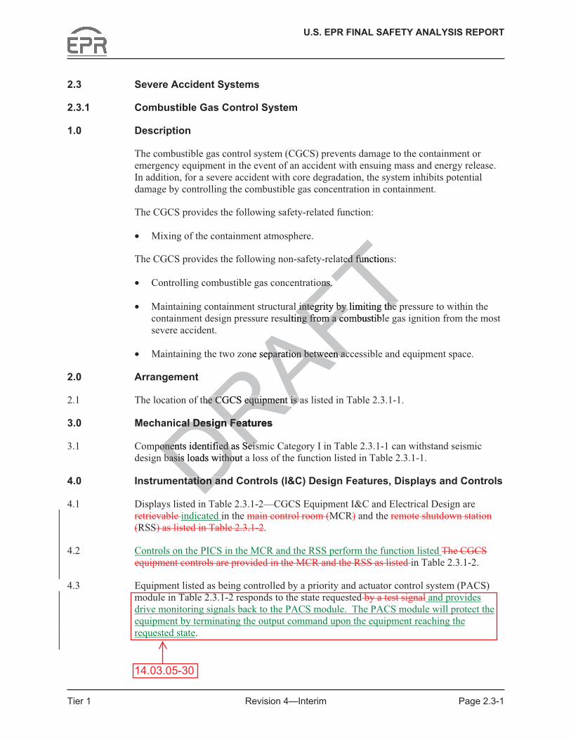
U.S. EPR FINAL SAFETY ANALYSIS REPORT
Tier 1 Revision 4—Interim Page 2.3-1
2.3 Severe Accident Systems
2.3.1 Combustible Gas Control System
1.0 Description
The combustible gas control system (CGCS) prevents damage to the containment or emergency equipment in the event of an accident with ensuing mass and energy release. In addition, for a severe accident with core degradation, the system inhibits potential damage by controlling the combustible gas concentration in containment.
The CGCS provides the following safety-related function:
• Mixing of the containment atmosphere.
The CGCS provides the following non-safety-related functions:
• Controlling combustible gas concentrations.
• Maintaining containment structural integrity by limiting the pressure to within the containment design pressure resulting from a combustible gas ignition from the most severe accident.
• Maintaining the two zone separation between accessible and equipment space.
2.0 Arrangement
2.1 The location of the CGCS equipment is as listed in Table 2.3.1-1.
3.0 Mechanical Design Features
3.1 Components identified as Seismic Category I in Table 2.3.1-1 can withstand seismic design basis loads without a loss of the function listed in Table 2.3.1-1.
4.0 Instrumentation and Controls (I&C) Design Features, Displays and Controls
4.1 Displays listed in Table 2.3.1-2—CGCS Equipment I&C and Electrical Design are retrievable indicated in the main control room (MCR) and the remote shutdown station (RSS) as listed in Table 2.3.1-2.
4.2 Controls on the PICS in the MCR and the RSS perform the function listed The CGCS equipment controls are provided in the MCR and the RSS as listed in Table 2.3.1-2.
4.3 Equipment listed as being controlled by a priority and actuator control system (PACS) module in Table 2.3.1-2 responds to the state requested by a test signal and provides drive monitoring signals back to the PACS module. The PACS module will protect the equipment by terminating the output command upon the equipment reaching the requested state.
14.03.05-30
DRAFTted functionsted fu
ons. ons.
l integrity by limiting the l integrity by limiting the ulting from a combustiblng from a c
ne separation between acparation between ac
the CGCS equipment is ahe CGCS equipment is
cal Design Features cal Design Fea
ponents identified as Seisponents identified as Seisbasis loads without abasis loads witho
ation anation an

U.S. EPR FINAL SAFETY ANALYSIS REPORT
Tier 1 Revision 4—Interim Page 2.3-9
Table 2.3.1-3—Combustible Gas Control System ITAAC (3 Sheets)
Commitment Wording Inspections, Tests,
Analyses Acceptance Criteria 4.2 Controls on the PICS in the
MCR and the RSS perform the function listed Controls exist in the MCR and the RSS as identified in Table 2.3.1-2.
a. Tests will be performed using controls on the PICS in the MCR.
a. The cControls on the PICS in the MCR perform the function listed in Table 2.3.1-2 as being in the MCR exist in the MCR.
b. Tests will be performed using controls on the PICS in the RSS.Tests will be performed for the existence of control signals from the MCR and the RSS to the equipment listed in Table 2.3.1-2.
b. The cControls on the PICS in the RSS perform the function listed in Table 2.3.1-2 as being in the RSS exist in the RSS.
4.3 Equipment listed as being controlled by a PACS module in Table 2.3.1-2 responds to the state requested by a test signal and provides drive monitoring signals back to the PACS module. The PACS module will protect the equipment by terminating the output command upon the equipment reaching the requested state.
A test will be performed using test signals.
Equipment listed as being controlled by a PACS module in Table 2.3.1-2 responds to the state requested by the test signal and provides drive monitoring signals back to the PACS module. The PACS module will protect the equipment by terminating the output command upon the equipment reaching the requested state.
5.1 Hydrogen mixing dampers listed in Table 2.3.1-1 fail open on loss of power.
Tests Testing will be performed for the hydrogen mixing dampers listed in Table 2.3.1-1 to fail open on loss of power.
Following loss of power, the hydrogen mixing dampers listed in Table 2.3.1-1 fail open.
14.03.05-30
FTTTence TTm th TFTS to t
FTFTed in
FTFTFTTTTTFT
DRRRto RDRDDRprotect
DRDRy
DDRhe out DDn the DDng theDDDRAFTAFTformed u
AFnals. FTTAFT
DRFT
DerDDRAFT

U.S. EPR FINAL SAFETY ANALYSIS REPORT
Tier 1 Revision 4—Interim Page 2.3-14
3.7 Deleted.
3.8 Deleted.
3.9 SAHRS piping shown as ASME Code Section III on Figure 2.3.3-1 is designed in accordance with ASME Code Section III requirements.
3.10 SAHRS piping shown as ASME Code Section III on Figure 2.3.3-1 is installed reconciled in accordance with an ASME Code Section III Design Report.
3.11 Pressure boundary welds in SAHRS piping shown as ASME Code Section III on Figure 2.3.3-1 are in accordance withmeet ASME Code Section III non-destructive examination requirements.
3.12 SAHRS piping shown as ASME Code Section III on Figure 2.3.3-1 retains pressure boundary integrity at design pressure.
3.13 SAHRS piping shown as ASME Code Section III on Figure 2.3.3-1 is fabricated, installed, and inspected in accordance with ASME Code Section III requirements.
3.14 Components listed in Table 2.3.3-1 as ASME Code Section III are designed in accordance with ASME Code Section III requirements.
3.15 Components listed in Table 2.3.3-1 as ASME Code Section III are fabricated reconciled in accordance with ASME Code Section III design requirements.
3.16 Pressure boundary welds on components listed in Table 2.3.3-1 as ASME Code Section III are in accordance with meet ASME Code Section III non-destructive examination requirements.
3.17 Components listed in Table 2.3.3-1 as ASME Code Section III retain pressure boundary integrity at design pressure.
3.18 Components listed in Table 2.3.3-1 as ASME Code Section III are fabricated, installed, and inspected in accordance with ASME Code Section III requirements.
3.19 Containment isolation valves are located close to containment penetrations.
4.0 I&C Design Features, Displays and Controls
4.1 Controls on the PICS in the MCR and the RSS perform the function listed The SAHRS equipment controls are provided in the MCR as listed in Table 2.3.3-2—SAHRS Equipment I&C and Electrical Design.
4.2 Equipment listed as being controlled by a priority and actuator control system (PACS) module in Table 2.3.3-2 responds to the state requested by a test signal and provides drive monitoring signals back to the PACS module. The PACS module will protect the equipment by terminating the output command upon the equipment reaching the requested state.
14.03.05-30
DRAFTgg
III on Figure 2.3.3III on FigurASME Code Section III ASME Code Sect
ASME Code Section III aASME Code Section III aon III requirements. II requireme
3.3-1 as ASME Code Sec.3-1 as ASME CodeCode Section III Section III design design AFrer
lds on components listed lds on componentse with e wit
Rmeet meet
RAASME CodeME
ts listed in Table 2.3.3-1 ts listed in Tabley at design pressure. y at design pressure.
onents listed in Tableonents listed in Tactedcted D in accorda in accorddd
olatolat
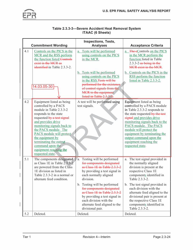
U.S. EPR FINAL SAFETY ANALYSIS REPORT
Tier 1 Revision 4—Interim Page 2.3-24
Table 2.3.3-3—Severe Accident Heat Removal System ITAAC (6 Sheets)
Commitment Wording Inspections, Tests,
Analyses Acceptance Criteria 4.1 Controls on the PICS in the
MCR and the RSS perform the function listed Controls exist in the MCR as identified in Table 2.3.3-2.
a. Tests will be performed using controls on the PICS in the MCR.
a. The cControls on the PICS in the MCR perform the function listed in Table 2.3.3-2 as being in the MCR exist in the MCR.
b. Tests will be performed using controls on the PICS in the RSS.Tests will be performed for the existence of control signals from the MCR to the equipment listed in Table 2.3.3-2.
b. Controls on the PICS in the RSS perform the function listed in Table 2.3.3-2.
4.2 Equipment listed as being controlled by a PACS module in Table 2.3.3-2 responds to the state requested by a test signaland provides drive monitoring signals back to the PACS module. The PACS module will protect the equipment by terminating the output command upon the equipment reaching the requested state.
A test will be performed using test signals.
Equipment listed as being controlled by a PACS module in Table 2.3.3-2 responds to the state requested by the test signal and provides drive monitoring signals back to the PACS module. The PACS module will protect the equipment by terminating the output command upon the equipment reaching the requested state.
a. Testing will be performed for components designated as Class 1E in Table 2.3.3-2 by providing a test signal in each normally aligned division.
a. The test signal provided in the normally aligned division is present at the respective Class 1E components identified in Table 2.3.3-2.
5.1 The components designated as Class 1E in Table 2.3.3-2 are powered from the Class 1E division as listed in Table 2.3.3-2 in a normal or alternate feed condition.
b. Testing will be performed for components designated as Class 1E in Table 2.3.3-2 by providing a test signal in each division with the alternate feed aligned to the divisional pair.
b. The test signal provided in each division with the alternate feed aligned to the divisional pair is present at the respective Class 1E components identified in Table 2.3.3-2.
5.2 Deleted. Deleted. Deleted.
14.03.05-30
DRAFTe e
the the Tent nt T.3.3
F--
F2.2
FTFTct ct Rput put
Dhe he
Daching the aching D
formed using formed usin Equipmeuipmcontrin FT
DRFT
aDDesignated esignated 2.3.3-2 2.3.3-2
asasDRAFT

U.S. EPR FINAL SAFETY ANALYSIS REPORT
Tier 1 Revision 4—Interim Page 2.4-26
2.4.2 Safety Information and Control System
1.0 Description
The safety information and control system (SICS) is provided as a safety-related human machine interface (HMI) and is specifically designed to provide the operator with the necessary inventory of controls and indications for the following:
� Mitigation of anticipated operational occurrences (AOO) (main control room (MCR)).
� Mitigation of postulated accidents (MCR).
� Reach and maintain safe shutdown (MCR and remote shutdown station (RSS)).
� Mitigation of anticipated operational occurrences (AOO) concurrent with a software common cause failure of the PS (MCR).
� Mitigation of postulated accidents (PA) concurrent with a software common cause failure of the PS (MCR).
� Mitigation of severe accidents (MCR).
The SICS provides the following safety-related functions:
� Manual reactor trip.
� Manual ESF actuation.
� Control of safety-related systems to reach and maintain safe shutdown.
� Indication of Type A, B, and C PAM variables.
2.0 Arrangement
2.1 The location of the SICS equipment is located as listed in Table 2.4.2-1—Safety Information and Control System Equipment.
2.2 Deleted..
2.3 Deleted.
2.4 Physical separation exists between Class 1E SICS equipment and non-Class 1E equipment.
2.5 Physical separation exists between the Class 1E electrical divisions that power the controls and indications of the SICS.
14.03.05-27
DRAFTtete
Tnces nces (AOO) (A Tc
A) A)
Fconcurrent with a softwconcurrent with a so
ts (MCR). ts
owing safety-related funcg safety-related funcArip.rip.
RF actuation.actuation.Rol of safety-related systemol of safety-related
DRndication of Type A, B, ndication of Type A, B, Dment ment
hhDRAF

U.S. EPR FINAL SAFETY ANALYSIS REPORT
Tier 1 Revision 4—Interim Page 2.4-27
3.0 Mechanical Design Features
3.1 Equipment identified as Seismic Category I in Table 2.4.2-1 can withstand seismic design basis loads without loss of safety function.
4.0 I&C Design Features, Displays and Controls
4.1 The capability to transfer control of the SICS from the MCR to the RSS exists in a fire area separate from the MCR. The transfer switches are each associated with a single division of the safety-related control and allow transfer of control without entry into the MCR.
4.2 Electrical isolation exists is provided between the Class 1E electrical divisions that power the controls and indications of the SICS as listed in Table 2.4.2-1.
4.3 Electrical isolation is provided on connections between the safety-related parts of the SICS and non-Class 1E equipment.
4.4 Class 1E SICS equipment listed in Table 2.4.2-1 can perform its safety function when subjected to electromagnetic interference (EMI), radio-frequency interference (RFI), electrostatic discharges (ESD), and power surges.
4.5 The SICS provides controls for manual actuation of reactor trip in the MCR and RSS.Deleted.
4.6 Electrical isolation is provided on connections between the RSS and the MCR for the SICS.
4.7 The SICS provides controls in the MCR for the manual actuation of the ESF functions listed in Table 2.4.2-2—Manually Actuated ESF Functions.Deleted.
4.8 The SICS provides indications of Type A, B, and C PAM variables in the MCR.Deleted.
4.9 The SICS provides, in the MCR, manual controls and indications necessary to reach and maintain safe shutdown following an AOO or PA.Deleted..
4.10 The SICS is designed so that safety-related functions required for an anticipated operational occurrence (AOO) or postulated accident (PA) are performed in the presence of the following:
� Single detectable failures within the SICS.
� Failures caused by the single failure.
� Failures and spurious system actions that cause or are caused by the AOO or PA requiring the safety function.
4.11 Locking mechanisms are provided on the SICS doors in the MCR and RSS. Opened SICS doors in the RSS are indicated in the MCR.Deleted.
14.03.05-27
DsignsignDRyRAFmanual actuation of reactotuation
AFvided on connections betn connections be
des controls in the MCR fes controls in the MCR RAe 2.4.2-2—Manually Actu2-2—Manually Actu
DRCS provides indications ofCS provides indication
DRCS provides, in the MCS provides, in thDsafe shutdown safe shutdownD
AFTen the sen the
2-1 2-1
FTcan c perform its saferform
FT(EMI), radio-frequency in(EMI), radio-frequencywer surges. wer surges.
DRAF

U.S. EPR FINAL SAFETY ANALYSIS REPORT
Tier 1 Revision 4—Interim Page 2.4-30
Table 2.4.2-2—Manually Actuated ESF Functions
Containment Isolation (Stage 1) Containment Isolation (Stage 2) CVCS Charging Isolation CVCS Isolation on Anti-Dilution MitigationEDG Actuation EFWS Actuation EFWS Isolation Extra Borating System Isolation Hydrogen Mixing Dampers Opening CRACS Isolation and Filtering Main Feedwater (MFW) Full Load Isolation Main Steam Isolation MSRIV Opening MSRT Isolation Partial Cooldown Actuation PSRV Opening RCP Trip SG Isolation SIS Actuation Turbine Trip
14.03.05-27DRAFTTTTFTFTAFAFARARARDRDR
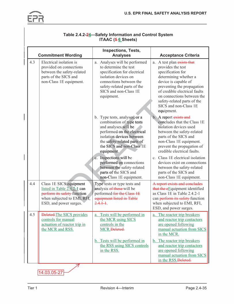
U.S. EPR FINAL SAFETY ANALYSIS REPORT
Tier 1 Revision 4—Interim Page 2.4-35
Table 2.4.2-24—Safety Information and Control System ITAAC (5 6 Sheets)
Commitment Wording Inspections, Tests,
Analyses Acceptance Criteria 4.3 Electrical isolation is
provided on connections between the safety-related parts of the SICS and non-Class 1E equipment.
a. Analyses will be performed to determine the test specification for electrical isolation devices on connections between the safety-related parts of the SICS and non-Class 1E equipment.
a. A test plan exists that provides the test specification for determining whether a device is capable of preventing the propagation of credible electrical faults on connections between the safety-related parts of the SICS and non-Class 1E equipment.
b. Type tests, analyses, or a combination of type tests and analyses will be performed on the electrical isolation devices between the safety-related parts of the SICS and non-Class 1E equipment.
b. A report exists and concludes that the Class 1E isolation devices used between the safety-related parts of the SICS and non-Class 1E equipment. prevent the propagation of credible electrical faults.
c. Inspections will be performed on connections between the safety-related parts of the SICS and non-Class 1E equipment.
c. Class 1E electrical isolation devices exist on connections between the safety-related parts of the SICS and non-Class 1E equipment.
4.4 Class 1E SICS equipment listed in Table 2.4.2-1 can perform its safety function when subjected to EMI, RFI, ESD, and power surges.
Type tests or type tests and analysis of these will be performed for the Class 1E equipment listed in Table 2.4.1-1.
A report exists and concludes that the eEquipment identified as Class 1E in Table 2.4.2-1 can perform its safety function when subjected to EMI, RFI, ESD, and power surges.
Deleted.The SICS provides controls for manual actuation of reactor trip in the MCR and RSS.
a. Tests will be performed in the MCR using SICS controls in the MCR.Deleted.
a. The reactor trip breakers and reactor trip contactors are opened following manual actuation from SICS in the MCR.
4.5
b. Tests will be performed in the RSS using SICS controls in the RSS.
b. The reactor trip breakers and reactor trip contactors are opened following manual actuation from SICS in the RSS.Deleted.
14.03.05-27
DRS equipmentS equ2.4.2-12.4.2- D can
function functMI, RFI, MI, RFI,
Type tType tanaaDRAFT
SequiTses, or a ses, or
f type tests f types will be s will
ed on the electrical the electrion devices between on devices betw
safety-related parts of afety-related parts ohe SICS and non-Class 1CS and non-Class 1
equipment. equipment.
b. A repob. AconclconisoFT
c. Inspections will bec. Inspections wperformed on coperformed onbetween the between the parts of thnon-Clno
DRDRDR

U.S. EPR FINAL SAFETY ANALYSIS REPORT
Tier 1 Revision 4—Interim Page 2.4-36
Table 2.4.2-24—Safety Information and Control System ITAAC (5 6 Sheets)
Commitment Wording Inspections, Tests,
Analyses Acceptance Criteria 4.6 Electrical isolation is
provided on connections between the RSS and the MCR for the SICS.
a. Analyses will be performed to determine the test specification for electrical isolation devices on connections between the RSS and the MCR for the SICS.
a. A test plan exists that provides the test specification for determining whether a device is capable of preventing the propagation of credible electrical faults on connections between the RSS and the MCR for the SICS.
b. Type tests, analyses, or a combination of type tests and analyses will be performed on the electrical isolation devices between the RSS and the MCR for the SICS.
b. A report exists and concludes that the Class 1E isolation devices used between the RSS and the MCR for the SICS prevent the propagation of credible electrical faults.
c. Inspections will be performed on connections between the RSS and the MCR for the SICS.
c. Class 1E electrical isolation devices exist on connections between the RSS and the MCR for the SICS.
4.7 The SICS provides controls in the MCR for manual actuation of the ESF functions listed in Table 2.4.2-2.Deleted.
Tests will be performed in the MCR using SICS controls in the MCR. Deleted.
The ESF functions shown in Table 2.4.2-2 are actuated following manual actuation from SICS in the MCR.Deleted.
4.8 The SICS provides indication of Type A, B, and C PAM variables in the MCR.Deleted.
Tests will be performed in the MCR using test signals.Deleted.
Type A, B, and C PAM variables are indicated on SICS in the MCR.Deleted.
a. An analysis will be performed.Deleted.
a. A report identifies the manual controls and indications necessary to reach and maintain safe shutdown in the MCR following an AOO or PA.Deleted.
b. Tests will be performed using controls on the SICS in the MCR.
b. Controls on the SICS in the MCR are verified to be functional.
4.9 The SICS provides, in the MCR, manual controls and indications necessary to reach and maintain safe shutdown following an AOO or PA.Deleted.
c. Tests will be performed in the MCR using test signals.
c. Displays on the SICS are indicated in the MCR.
14.03.05-27
S
T, or a or a ype tests ype te
will be will beon the electrical n the electrica
devices between ces betweeSS and the MCR for SS and the MCR
SICS. ICS.
b. A repbconcludisolatisobebFT
Inspections will be tions will be performed on connectperformed on connectbetween the RSS abetween the MCR for the SIMCR for the Rontrols s
DRnual nual
DESF ESF
Dd in Table d in DTests will be peTests will be pe
DRMCR using MC
DRthe MCRhe M
DRRADR
B, andB, andDDDRA

U.S. EPR FINAL SAFETY ANALYSIS REPORT
Tier 1 Revision 4—Interim Page 2.4-37
� By introducing and varying, a substitute input of the same nature as the measured variable.
� By cross-checking between channels that bear a known relationship to each other.
� By specifying equipment that is stable and the period of time it retains its calibration during post-accident conditions.
4.16 Deleted.
4.17 Hardwired disconnects exist between the service unit (SU) and each divisional monitoring and service interface (MSI) of the SAS. The hardwired disconnects prevent the connection of the SU to more than a single division of the SAS.
4.18 The SAS performs the automatic functions listed in Table 2.4.4-5—Safety Automation System Automatic Functions.
4.19 During data communication, the SAS function processors receive only the pre-defined messages for that specific function processor. Other messages are ignored.
4.20 SAS self-test features are capable of detecting faults consistent with the requirements of the SAS.
4.21 SAS connections to the SICS are hardwired for manual grouped controls.
4.22 SAS manual grouped controls and indications are available on the SICS in the MCR.
4.23 Permissive P15 provides operating bypass capability for the following SAS functions:
� Safety Injection and Heat Removal System - Automatic Trip of LHSI Pump (in RHR Mode) on Low Delta Psat.
� Safety Injection and Heat Removal System - Automatic Trip of LHSI Pump (in RHR Mode) on Low Loop Level.
5.0 Electrical Power Design Features
5.1 Class 1E SASThe components designated as Class 1E in Table 2.4.4-1 are powered from a Class 1E division as listed in Table 2.4.4-1 in a normal or alternate feed condition.
6.0 Environmental Qualification
6.1 Components listed as Class 1E in Table 2.4.4-1 can perform their function under normal environmental conditions, AOOs, and accident and post-accident environmental conditions.
6.07.0 System Inspections, Tests, Analyses, and Acceptance Criteria
Table 2.4.4-6 lists the SAS ITAAC.
14.03.05-41
j RAFare hardwired for manualre hardwired for manAFntrols and indications ared indications are
RAovides operating bypass covides operating bypa
RAjection and Heat Removan and Heat Remova
DR) on Low Delta Psat.) on Low Delta P
DRafety Injection and Heatafety Injection and HeatDde) on Low Loop Lde) on Low LoopDower Dower D
AFTetecting faults consistent etecting faults consistent FTFTbleble
processors receive processors rTr. Other messages are igr. Other message
FTAFT
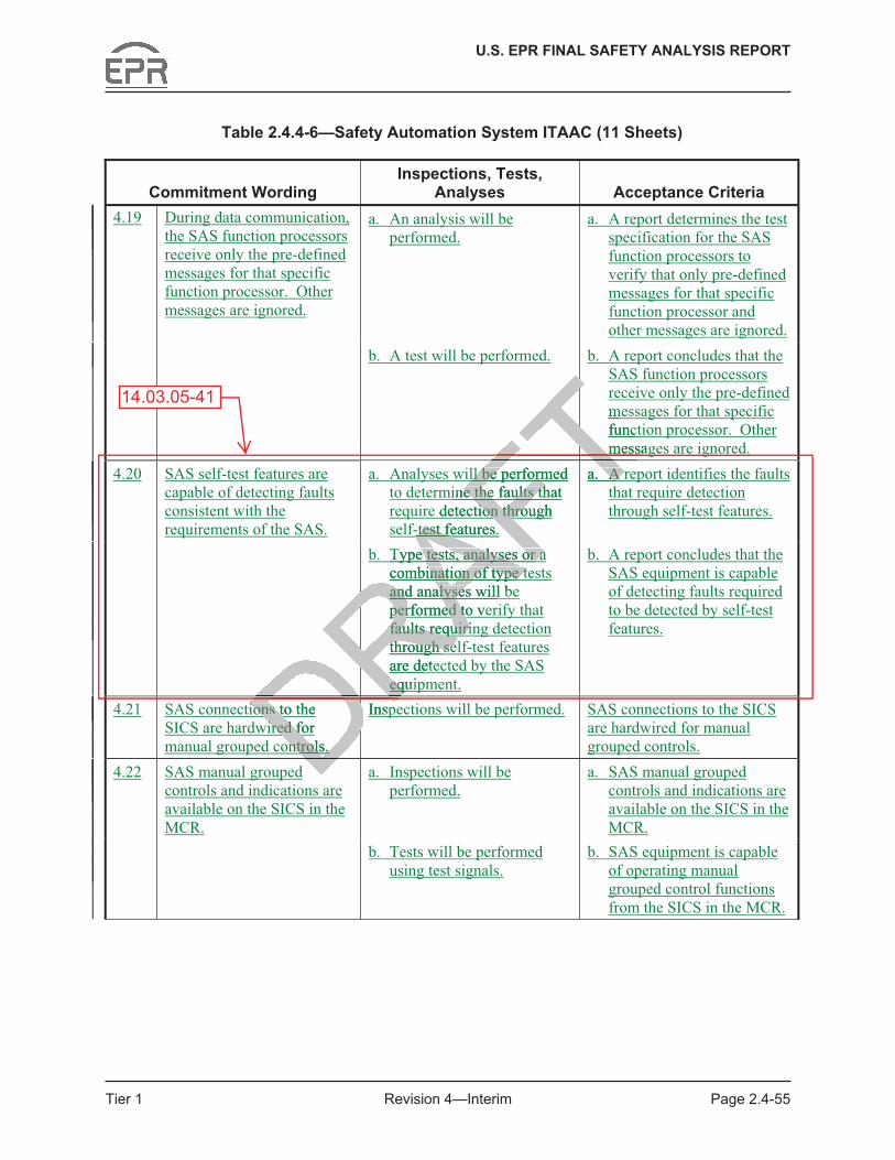
U.S. EPR FINAL SAFETY ANALYSIS REPORT
Tier 1 Revision 4—Interim Page 2.4-55
Table 2.4.4-6—Safety Automation System ITAAC (11 Sheets)
Commitment Wording Inspections, Tests,
Analyses Acceptance Criteria a. An analysis will be
performed. a. A report determines the test
specification for the SAS function processors to verify that only pre-defined messages for that specific function processor and other messages are ignored.
4.19 During data communication, the SAS function processors receive only the pre-defined messages for that specific function processor. Other messages are ignored.
b. A test will be performed. b. A report concludes that the SAS function processors receive only the pre-defined messages for that specific function processor. Other messages are ignored.
a. Analyses will be performed to determine the faults that require detection through self-test features.
a. A report identifies the faults that require detection through self-test features.
4.20 SAS self-test features are capable of detecting faults consistent with the requirements of the SAS.
b. Type tests, analyses or a combination of type tests and analyses will be performed to verify that faults requiring detection through self-test features are detected by the SAS equipment.
b. A report concludes that the SAS equipment is capable of detecting faults required to be detected by self-test features.
4.21 SAS connections to the SICS are hardwired for manual grouped controls.
Inspections will be performed. SAS connections to the SICS are hardwired for manual grouped controls.
a. Inspections will be performed.
a. SAS manual grouped controls and indications are available on the SICS in the MCR.
4.22 SAS manual grouped controls and indications are available on the SICS in the MCR.
b. Tests will be performed using test signals.
b. SAS equipment is capable of operating manual grouped control functions from the SICS in the MCR.
14.03.05-41mTfunctTmessag
FTll be performed ll be performFTine the faults that e the faults th
AFTe detection through ion thro
AF-test features.-test features.
AFa. A rA rTtFTFTFTFTType tests, analyses or a e tests, analyses or aAcombination of type teination of type t
RAand analyses will band analyses
RAperformed to verperformed toRAfaults requirinfaults requiriRAthrough sethrough seRare deteRequipeqRDRions to the ions t Dired for ired f Dontrols.ontrols.DInspDDRDRDDRAFT

U.S. EPR FINAL SAFETY ANALYSIS REPORT
Tier 1 Revision 4—Interim Page 2.4-57
2.4.5 Priority and Actuator Control System
1.0 Description
The priority and actuator control system (PACS) is a safety-related system.
The PACS provides the following safety-related functions:
� Prioritizes actuation requests from I&C systems.
� Performs essential equipment protection.
� Performs drive actuation.
� Performs drive monitoring.
2.0 Arrangement
2.1 The location of the PACS equipment is located as listed in Table 2.4.5-1—Priority and Actuator Control System Equipment.
2.2 Physical separation exists between the four divisions of the PACS as listed in Table 2.4.5-1.
2.3 Physical separation exists between Class 1E PACS equipment and non-Class 1E equipment.
3.0 Mechanical Design Features
3.1 Equipment identified as Seismic Category I in Table 2.4.5-1 can withstand seismic design basis loads without loss of safety function.
4.0 I&C Design Features, Displays and Controls
4.1 Protection system (PS) and Diverse Actuation System (DAS) signals received by each priority module override other signals received by the priority module.
4.2 Electrical isolation is provided on connections between Class 1E PACS equipment and non-Class 1E equipment.
4.3 Class 1E PACS equipment listed in Table 2.4.5-1 can perform its safety function when subjected to electromagnetic interference (EMI), radio-frequency interference (RFI), electrostatic discharges (ESD), and power surges.
4.4 The input wiring from other I&C systems to the PACS is properly connected.
4.5 The capability for testing of the PACS is provided while retaining the capability of the PACS to accomplish its safety function. PACS divisions in test are indicated in the MCR.
14.03.05-30DRAFTcated cated
Fas listed in Table 2Table
n the four
AFdivisions of thedivis
s between Class 1E PACn Class 1E PAC
esign Features sign Features
t identified as Seismic Cat identified as Seads without loss of safetyads without loss of saf
esign Features, Design Features
ystem (PSystem (PSovov

U.S. EPR FINAL SAFETY ANALYSIS REPORT
Tier 1 Revision 4—Interim Page 2.4-67
Table 2.4.5-3—Priority and Actuator Control System ITAAC (5 Sheets)
Commitment Wording Inspections, Tests,
Analyses Acceptance Criteria 3.1 Equipment identified as
Seismic Category I in Table 2.4.5-1 can withstand seismic design basis loads without loss of safety function.
a. Type tests, analyses or a combination of type tests and analyses will be performed on the equipment listed as Seismic Category I in Table 2.4.5-1 using analytical assumptions, or under conditions, which bound the Seismic Category I design requirements.
a. Tests/analysis reports exist and conclude that the equipment listed as Seismic Category I in Table 2.4.5-1 can withstand seismic design basis loads without loss of safety function.
b. Inspections will be performed of the Seismic Category I equipment listed in Table 2.4.5-1 to verify that the equipment including anchorage is installed as specified per seismic qualification report (SQDP, EQDP, or analyses) requirementson the construction drawings.
b. Inspection reports exist and conclude that the Seismic Category I equipment listed in Table 2.4.5-1 including anchorage is installed as specified per seismic qualification report (SQDP, EQDP, or analyses) requirementson the construction drawings.
4.1 PS and DAS signals received by each priority module override other signals received by the priority module
Tests A test will be performed using test signals. that verify PS signals received by each priority modules override other signals received by the priority module.
Test results exist and conclude that theThe PS and DAS signals received by each priority module override other signals received by the priority modules.
14.03.05-30 14.03.05-30
DRgnals received gnals receivedity module ity mr signals r signa
priority priority
Tests Te
DRDRAFTFTwill be will bd of the Seismic d of the Seism
ory I equipment equipmentd in Table 2.4.5-1 to d in Table 2.4.5
verify that the equipment rify that the equipmeincluding anchorage is uding anchorage is installed as specifiedlled as specifiedseismic qualificatseismic qu
RAreport (SQDP,report (SQDRAanalyses) reanalyses) reRthe constconstR
b. Inspeb. Insco
DRFT
A perfoperfothaDDRDRDRDR30

U.S. EPR FINAL SAFETY ANALYSIS REPORT
Tier 1 Revision 4—Interim Page 2.5-42
3.24 Components listed in Table 2.5.4-1 as ASME Code Section III retain pressure boundary integrity at design pressure.
3.25 Components listed in Table 2.5.4-1 as ASME Code Section III are fabricated, installed, and inspected in accordance with ASME Code Section III requirements.
4.0 I&C Design Features, Alarms, Displays and Controls
4.1 Displays listed in Table 2.5.4-2 and Table 2.5.4-3 are retrievable indicated in the main control room (MCR) and the remote shutdown station (RSS) as listed in Table 2.5.4-2 and Table 2.5.4-3.
4.2 Controls on the PICS in the MCR and the RSS perform the function listed in Table 2.5.4-2.EDG equipment controls are provided in the MCR and RSS as listed in Table 2.5.4-2 and Table 2.5.4-3.
4.3 Equipment listed as being controlled by a priority and actuator control system (PACS) module in Table 2.5.4-2 responds to the state requested by a test signal and provides drive monitoring signals back to the PACS module. The PACS module will protect the equipment by terminating the output command upon the equipment reaching the requested state.
5.0 Electrical Considerations
5.1 The EDG control power is provided by the EUPS system from the respective division.
5.2 The components identified designated as Class 1E in Table 2.5.4-2 are powered from the Class 1E division listed in Table 2.5.4-2.
5.3 Each EDG output rating is greater than the analyzed loads assigned in the respective emergency power supply system (EPSS) division and loads capable of being connected to the EPSS division through the alternate feed.
5.4 Valves listed in Table 2.5.4-2 fail to the position as shown in Table 2.5.4-2 on loss of power.
6.0 Equipment and System Performance
6.1 Each EDG is started by a protection system loss of offsite power (LOOP) signal from the respective EPSS division medium voltage bus.
6.2 Each EDG is started by a protection system safety injection system (SIS) actuation signal.
6.3 Each EDG will start and connect to the respective EPSS division medium voltage bus in an undervoltage condition concurrent with a SIS actuation signal.
6.4 The EDG lubricating oil system heat exchangers listed in Table 2.5.4-1 have the capacity to transfer the design heat load to the essential service water system.
6.5 Class 1E valves listed in Table 2.5.4-2 can perform the will function to change position as listed in Table 2.5.4-1 under system operating conditions.
14.03.05-30
DRAFTprovided by the EUPS sysded by the EUPS syFTquestedquested TbbbTyyTTaTTtTeTsTtTTs
module. The PACS modmodule. The PAC
FTmand upon the equipmenmand upon the equipm
FTTand actuator and a
ified ified
RAdesignated designated
RAas Class assted in Table 2.5.4-2. sted in Table 2.5.4-2
utput rating is greater thanrating is greater thany power supply system (E power supply sy
S division through the altS division through the
listed in Table 2.5.4listed in Table 2
ndnd
FT

U.S. EPR FINAL SAFETY ANALYSIS REPORT
Tier 1 Revision 4—Interim Page 2.5-72
Table 2.5.4-4—Emergency Diesel Generator ITAAC (9 Sheets)
Commitment Wording Inspections, Tests,
Analyses Acceptance Criteria 4.3 Equipment listed as being
controlled by a PACS module in Table 2.5.4-2 responds to the state requested by a test signal and provides drive monitoring signals back to the PACS module. The PACS module will protect the equipment by terminating the output command upon the equipment reaching the requested state.
A test will be performed using test signals.
Equipment listed as being controlled by a PACS module in Table 2.5.4-2 responds to the state requested by the signal and provides drive monitoring signals back to the PACS module. The PACS module will protect the equipment by terminating the output command upon the equipment reaching the requested state.
5.1 The EDG control power is provided by the EUPS system from the respective division.
A test will be performed on each EDG system by providing a test signal in only one division.
The test signal exists in only the EDG system under test when a test signal is applied in each EDG system.
5.2 The components identified designated as Class 1E in Table 2.5.4-2 are powered from the Class 1E division listed in Table 2.5.4-2.
A test will be performed for components identified as Class 1E in Table 2.5.4-2 by providing a test signal in each division.
The test signal provided in each division is present at the respective Class 1E components identified in Table 2.5.4-2.
5.3 Each EDG output rating is greater than the analyzed loads assigned in the respective EPSS division and loads capable of being connected to the EPSS division through the alternate feed.
a. An analysis will be performed.
a. Analysis concludes each specified EDG output rating is greater than the analyzed loads assigned in the respective EPSS divisions. and loads capable of being connected to the EPSS division through the alternate fee
b. A test will be performed. b. Each installed EDG provides an output power capacity greater than the analyzed loads.
5.4 Valves listed in Table 2.5.4-2 fail to the position as shown in Table 2.5.4-2 on loss of power.
Tests Testing will be performed for the valves listed in Table 2.5.4-2 to verify the position of valves on loss of power.
Following the loss of power, the valves listed in Table 2.5.4-2 fail to the position as shown in Table 2.5.4-2.
14.03.05-30
DRAFTrformed rform on
FTstem tem Fby providing by providal in only one only one
The testThe tethe EEwFTFTFTFT
est will be performed will be performed for forFomponents ideents ide
RAntified as Cntified as CA1E in Table 2.5.41E in Table 2.5.4
RA-A2 Aby providing a test signproviding a tesdivision. visio AFRing is
nalyzed nalyzed in the in the
SSSS
FTeq
Toutp
TequipmTrequestedreqTFT division and division and Df being f beingDPSS PSS DalternatealternateD
a. An analysa. An analysperformRRRA
DRFT

U.S. EPR FINAL SAFETY ANALYSIS REPORT
Tier 1 Revision 4—Interim Page 2.6-2
2.3 Physical separation exists between the CRACS air intake, iodine filtration, air recirculation, and air conditioning trains as listed in Table 2.6.1-1.
3.0 Mechanical Design Features
3.1 Deleted.
3.2 Class 1E dampers Equipment listed in Table 2.6.1-1 will can perform the function to change position as listed in Table 2.6.1-1 under system operating conditions.
3.3 Components identified as Seismic Category I in Table 2.6.1-1 can withstand seismic design basis loads without a loss of the function listed in Table 2.6.1-1.
3.4 Components listed in Table 2.6.1-1 as ASME AG-1 Code are designed in accordance with ASME AG-1 Code requirements.
3.5 Components listed in Table 2.6.1-1 as ASME AG-1 Code are fabricated in accordance with ASME AG-1 Code requirements, including welding requirements.
3.6 Components listed in Table 2.6.1-1 as ASME AG-1 Code are installed, inspected and tested in accordance with ASME AG-1 Code requirements.
4.0 Displays and Controls
4.1 Displays listed in Table 2.6.1-2—Main Control Room Air Conditioning System Equipment I&C and Electrical Design, are retrievable indicated in the main control room (MCR) and the remote shutdown station (RSS) as listed in Table 2.6.1-2.
4.2 Controls on the PICS in the MCR and the RSS perform the function listed in Table 2.6.1-2.The CRACS equipment controls are provided in the MCR and RSS as listed in Table 2.6.1-2.
4.3 Equipment listed as being controlled by a priority and actuator control system (PACS) module in Table 2.6.1-2 responds to the state requested by a test signal and provides drive monitoring signals back to the PACS module. The PACS module will protect the equipment by terminating the output command upon the equipment reaching the requested state.
5.0 Electrical Power Design Features
5.1 The equipment designated as Class 1E in Table 2.6.1-2 are powered from the Class 1E division as listed in Table 2.6.1-2 in a normal or alternate feed condition.
5.2 Deleted.
6.0 Equipment and System Performance
6.1 The CRACS maintains a positive pressure in the CRE area relative to the outside environment and adjacent areas, while operating in a design basis accident alignment.
6.2 Upon receipt of a containment isolation signal (CIS), the iodine filtration train will start automatically, outside air supply to the CRE area is diverted through the iodine filtration
14.03.05-30
DRAFT1 Code are f1 Cod
g welding requiremg welding r
ME AG-1 Code are ME AG-1 Code are instalinTCode requirements. Code require
1-2—Main Control Room—Main Control Rootrical Design, are esign, are retrievaretrievAe shutdown station (RSS)e shutdown station
PICS in the MCR and thePICS in the MCR and thRAS equipment controls are uipment controls are
DRment listed as being contment listed as being cone in Table 2.6.1-2 rese in Table 2.6.1-2
nitoring signalsnitoring signalDy terminay terminaDD

U.S. EPR FINAL SAFETY ANALYSIS REPORT
Tier 1 Revision 4—Interim Page 2.6-18
Table 2.6.1-3—Main Control Room Air Conditioning System ITAAC (7 Sheets)
Commitment Wording Inspections, Tests,
Analyses Acceptance Criteria 4.3 Equipment listed as being
controlled by a PACS module in Table 2.6.1-2 responds to the state requested by a test signal and provides drive monitoring signals back to the PACS module. The PACS module will protect the equipment by terminating the output command upon the equipment reaching the requested state.
A test will be performed using a test signal.
Equipment listed as being controlled by a PACS module in Table 2.6.1-2 responds to the state requested by a test signal and provides drive monitoring signals back to the PACS module. The PACS module will protect the equipment by terminating the output command upon the equipment reaching the requested state.
a. Testing will be performed for the components designated as Class 1E in Table 2.6.1-2 by providing a test signal in each normally aligned division.
a. The test signal provided in the normally aligned division is present at the respective Class 1E components identified in Table 2.6.1-2.
5.1 The components designated as Class 1E in Table 2.6.1-2 are powered from the Class 1E division as listed in Table 2.6.1-2 in a normal or alternate feed condition. b. Testing will be performed
for the components designated as Class 1E in Table 2.6.1-2 by providing a test signal in each division with the alternate feed aligned to the divisional pair.
b. The test signal provided in each division with the alternate feed aligned to the divisional pair is present at the respective Class 1E components identified in Table 2.6.1-2.
5.2 Deleted. Deleted. Deleted. 6.1 The CRACS maintains a
positive pressure in the CRE area relative to the outside environment and adjacent areas, while operating in a design basis accident alignment.
A tests will be performed to verify that the CRACS maintains a positive pressure in the CRE area relative to the outside environment and adjacent areas, while operating in a design basis accident alignment.
The test confirms that the CRACS maintains a positive pressure of greater than or equal to 0.125 inches water gauge in the CRE area relative to the outside environment and adjacent areas, while operating in a design basis accident alignment.
14.03.05-30
DRAFTwill be performed be performe components e components
AFsignated as Class 1E in gnated as Class 1E inAFTable 2.6.12.6 A-AF2 2AFby providinby providinba test signal in each a test signal in each normally aligned dnormally ali
a.
RFT
b. Testing will beTesting will bfor the compfor the compRdesignate
FTeqe
Toutpu
TequipmeeTrequested srequ
FTFTFTFTFTFTRTable TRa tea tedRDRD
FT

U.S. EPR FINAL SAFETY ANALYSIS REPORT
Tier 1 Revision 4—Interim Page 2.6-27
3.3 Components identified as Seismic Category I in Table 2.6.3-1 can withstand seismic design basis loads without a loss of the function listed in Table 2.6.3-1.
3.4 Components listed in Table 2.6.3-1 as ASME AG-1 Code are designed in accordance with ASME AG-1 Code requirements.
3.5 Components listed in Table 2.6.3-1 as ASME AG-1 Code are fabricated in accordance with ASME AG-1 Code requirements, including welding requirements.
3.6 Components listed in Table 2.6.3-1 as ASME AG-1 Code are installed, inspected and tested in accordance with ASME AG-1 Code requirements.
4.0 Displays and Controls
4.1 Displays listed in Table 2.6.3-2—Annulus Ventilation System Equipment I&C and Electrical Design, are retrievable indicated in the main control room (MCR) and the remote shutdown station (RSS) as listed in Table 2.6.3-2.
4.2 Controls on the PICS in the MCR and the RSS perform the function listed in Table 2.6.3-2.The AVS equipment controls exist in the MCR and RSS as listed in Table 2.6.3-2.
4.3 Equipment listed as being controlled by a priority and actuator control system (PACS) module in Table 2.6.3-2 responds to the state requested by a test signal and provides drive monitoring signals back to the PACS module. The PACS module will protect the equipment by terminating the output command upon the equipment reaching the requested state.
5.0 Electrical Power Design Features
5.1 The equipment designated as Class 1E in Table 2.6.3-2 are powered from the Class 1E division as listed in Table 2.6.3-2 in a normal or alternate feed condition.
5.2 Deleted.
6.0 Environmental Qualifications
6.1 Components designated as harsh environment in Table 2.6.3-2, that are designated as harsh environment, will perform the function listed in Table 2.6.3-1 under normal environmental conditions, containment test conditions, anticipated operational occurrences, and accident and post-accident environmental conditions.in the environments that exist during and following design basis events.
7.0 Equipment and System Performance
7.1 The AVS provides a negative pressure between the inner and outer containment shells during postulated accidents.
7.2 Upon receipt of containment isolation signal, the following actions occur automatically:
• Isolation of the normal operation train by closing the isolation dampers listed in Table 2.6.3-1 for Normal Operation Train.
14.03.05-30
DRAFTyy
n contrn con.6.3.6.3
T-
T2
T.
SS perform the functionSS perform the fu
FTe MCR and RSS as listede MCR and RSS as lis
FTd by a priority and actuatoy a priority a to the state requestedate req bydFto the PACS module. Tho the PACS module
AFhe output command uponutput command uponAFr Design Features r Design Features
nt designated as Class 1E signated as Class 1Elisted in Table 2.6.3-2 inlisted in Table
ed. ed.
mental Qualifmental Qual
signsign
RAF

U.S. EPR FINAL SAFETY ANALYSIS REPORT
Tier 1 Revision 4—Interim Page 2.6-35
Table 2.6.3-3—Annulus Ventilation System ITAAC (4 Sheets)
Commitment Wording Inspections, Tests,
Analyses Acceptance Criteria 4.1 Displays listed in Table
2.6.3-2 are retrievable indicated in the MCR and the RSS as listed in Table 2.6.3-2.
a. Tests will be performed in the MCR using test signals.Tests will be performed for the retrieve-ability of the displays in the MCR as listed in Table 2.6.3-2.
a. The dDisplays listed in Table 2.6.3-2 are indicated as being retrieved in the MCR can be retrieved in the MCR.
b. Tests will be performed in the RSS using test signals.Tests will be performed for the retrieve-ability of the displays in the RSS as listed in Table 2.6.3-2.
b. The dDisplays listed in Table 2.6.3-2 are indicated as being retrieved in the RSS can be retrieved in the RSS.
4.2 Controls on the PICS in the MCR and the RSS perform the function listed in Table 2.6.3-2.Controls exist in the MCR and the RSS as identified in Table 2.6.3-2.
a. Test will be performed for the existence of control signals from using controls on the PICS in the MCR to the equipment listed in Table 2.6.3-2.
a. The cControls on the PICS in the MCR perform the function listed in Table 2.6.3-2 as being in the MCR exist in the MCR.
b. Test will be performed for the existence of control signals from using controls on the PICS in the RSS to the equipment listed in Table 2.6.3-2.
b. The cControls on the PICS in the RSS perform the function listed in Table 2.6.3-2 as being in the RSS exist in the RSS.
4.3 Equipment listed as controlled by a PACS module in Table 2.6.3-2 responds to the state requested by a test signal and provides drive monitoring signals back to the PACS module. The PACS module will protect the equipment by terminating the output command upon the equipment reaching the requested state.
A test will be performed using test signals.
Equipment listed as being controlled by a PACS module in Table 2.6.3-2 responds to the state requested by the test signal and provides drive monitoring signals back to the PACS module. The PACS module will protect the equipment by terminating the output command upon the equipment reaching the requested state.
14.03.05-30 DRAFTbe performed ormed for fo
AFtence of control tence of control
AFals from from Ausing controls using controls AFn the PICS in ICS
RAthe MCRthe MCR totoRRAthe equipment listed in the equipment listed in
RATable 2.6.3Table
FThe he
FSS as listed SS as
FT2.2. Fb.b.
Tas beTRSS caTRSS. RS
FTRA--
RA22RA. . a. TFT
RFT
b. Test will be peb. Test will be pethe existencth
DRsignals fsignal
DRon thetheDtheDDRDDDDDD

U.S. EPR FINAL SAFETY ANALYSIS REPORT
Tier 1 Revision 4—Interim Page 2.6-57
• Confines the volume of the containment by maintaining negative pressure and removing iodine released in the event of a fuel handling accident in the Reactor Building.
2.0 Arrangement
2.1 The functional arrangement of the SBVS is as shown on the following figures:
• Figure 2.6.6-1—Safeguard Building Controlled-Area Ventilation System Air Supply Functional Arrangement.
• Figure 2.6.6-2—Safeguard Building Controlled-Area Ventilation System Exhaust Air Functional Arrangement.
2.2 The location of the SBVS equipment is as listed in Table 2.6.6-1—Safeguard Building Controlled-Area Ventilation System Equipment Mechanical Design.
2.3 Physical separation exists between the SBVS iodine filtration trains located in the Fuel Building as listed in Table 2.6.3-1.
3.0 Mechanical Design Features
3.1 Deleted.
3.2 Class 1E dampers Equipment listed in Table 2.6.6-1 will can perform the function to change position as listed in Table 2.6.6-1 under system operating conditions.
3.3 Components identified as Seismic Category I in Table 2.6.6-1 can withstand seismic design basis loads without a loss of the function listed in Table 2.6.6-1.
3.4 Components listed in Table 2.6.6-1 as ASME AG-1 Code are designed in accordance with ASME AG-1 Code requirements.
3.5 Components listed in Table 2.6.6-1 as ASME AG-1 Code are fabricated in accordance with ASME AG-1 Code requirements, including welding requirements.
3.6 Components listed in Table 2.6.6-1 as ASME AG-1 Code are installed, inspected and tested in accordance with ASME AG-1 Code requirements.
4.0 Displays and Controls
4.1 Displays listed in Table 2.6.6-2—Safeguard Building Controlled-Area Ventilation System Equipment I&C and Electrical Design, are retrievable indicated in the main control room (MCR) and the remote shutdown station (RSS) as listed in Table 2.6.6-2.
4.2 Controls on the PICS in the MCR and the RSS perform the function listed in Table 2.6.6-2.The SBVS equipment controls that are provided in the MCR and RSS are as listed in Table 2.6.6-2.
4.3 Equipment listed as being controlled by a priority and actuator control system (PACS) module in Table 2.6.6-2 responds to the state requested by a test signal and provides
14.03.05-30
DRAFTle 2le 2
hanical hanic
dine filtration traindine filtrat
nt Alisted in Table 2.6.6-1 ted in Table 2.6.6-1in Table 2.6.6-1 under sy2.6.6-1 under sy
fied as Seismic Categoryfied as Seismic Categds without a loss of the fus without a loss of the f
nts listed in Table 2.6.6-1 nts listed in TableSME AG-1 Code requiremSME AG-1 Code requi
nents listed in Tablenents listed in TaME AG-1 CodeME AG-1 Code
tedted

U.S. EPR FINAL SAFETY ANALYSIS REPORT
Tier 1 Revision 4—Interim Page 2.6-58
drive monitoring signals back to the PACS module. The PACS module will protect the equipment by terminating the output command upon the equipment reaching the requested state.
5.0 Electrical Power Design Features
5.1 The equipment designated as Class 1E in Table 2.6.6-2 are powered from the Class 1E division as listed in Table 2.6.6-2 in a normal or alternate feed condition.
5.2 Deleted.
6.0 Environmental Qualifications
6.1 Components designated as harsh environment in Table 2.6.6-2, that are designated as harsh environment, will perform the function listed in Table 2.6.6-1 under normal environmental conditions, containment test conditions, anticipated operational occurrences, and accident and post-accident environmental conditions.in the environments that exist during and following design basis events.
6.2 Deleted.
7.0 Equipment and System Performance
7.1 Upon receipt of a containment isolation signal, the SBVS maintains a negative pressure in the hot mechanical rooms of the Safeguard Buildings relative to the adjacent areas.
7.2 Deleted.
7.3 Upon receipt of a high radiation signal in the FB, both SBVS iodine filtration trains start automatically, the isolation dampers open, and the accident air is directed through the SBVS iodine filtration trains.
7.4 Upon receipt of a containment isolation signal, the SBVS is isolated from the SBVSE and NAVBS by automatically closing the air supply and exhaust isolation dampers, both SBVS iodine filtration trains start automatically, and the FB and SB exhaust air is directed through the iodine filtration trains to maintain a negative pressure inside the FB and hot mechanical area of the SB.
7.5 The SBVS provides recirculation cooling to maintain design temperatures in the hot mechanical rooms in the Safeguard Buildings, while operating in a design basis accident alignment.
8.0 Inspections, Tests, Analyses and Acceptance Criteria
Table 2.6.6-3 lists the SBVS ITAAC.
14.03.05-30
DRAFTs, antics, ant
Tonmental cononmen
Tesign basis events.esign basis Tmance nce
isolation signal, the SBVsolation signal, thes of the Safeguard Buildinthe Safeguard Buildi
a high radiation signal in a high radiation signal in, the isolation dampers opisolation dampers op
ne filtration trains. ne filtration trai
receipt of a containmentreceipt of a containmentS by automatically cS by automatical
dine filtration trdine filtration tugh the iough the io
nicanica

U.S. EPR FINAL SAFETY ANALYSIS REPORT
Tier 1 Revision 4—Interim Page 2.6-75
Table 2.6.6-3—Safeguard Building Controlled-Area Ventilation System ITAAC (7 Sheets)
Commitment Wording Inspections, Tests,
Analyses Acceptance Criteria 4.3 Equipment listed as being
controlled by a PACS module in Table 2.6.6-2 responds to the state requested by a test signaland provides drive monitoring signals back to the PACS module. The PACS module will protect the equipment by terminating the output command upon the equipment reaching the requested state.
A test will be performed using test signals.
Equipment listed as being controlled by a PACS module in Table 2.6.6-2 responds to the state requested by the test signal and provides drive monitoring signals back to the PACS module. The PACS module will protect the equipment by terminating the output command upon the equipment reaching the requested state.
a. Testing will be performed for the components designated as Class 1E in Table 2.6.6-2 by providing a test signal in each normally aligned division.
a. The test signal provided in the normally aligned division is present at the respective Class 1E components identified in Table 2.6.6-2.
5.1 The components designated as Class 1E in Table 2.6.6-2 are powered from the Class 1E division as listed in Table 2.6.6-2 in a normal or alternate feed condition.
b. Testing will be performed for the components designated as Class 1E in Table 2.6.6-2 by providing a test signal in each division with the alternate feed aligned to the divisional pair.
b. The test signal provided in each division with the alternate feed aligned to the divisional pair is present at the respective Class 1E components identified in Table 2.6.6-2.
5.2 Deleted. Deleted. Deleted.
14.03.05-30
DRAFTwill be performed e performecomponents components
AFgnated as Class 1E in nated as Class 1E in AFable 2.6.62.6. A-A2 2AFby providingby providinga test signal in each a test signal in each normally aligned divnormally alig
a.
RFT
b. Testing will be pTesting will befor the compofor the compoR
FTeque
Toutpu
TequipmeeTrequested srequ
FTFTFTFTFTFTdesignatedd
DRTable 2Tab
DRa testa teswRDRD
FT
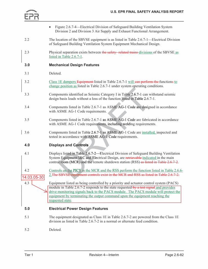
U.S. EPR FINAL SAFETY ANALYSIS REPORT
Tier 1 Revision 4—Interim Page 2.6-82
• Figure 2.6.7-4—Electrical Division of Safeguard Building Ventilation System Division 2 and Division 3 Air Supply and Exhaust Functional Arrangement.
2.2 The location of the SBVSE equipment is as listed in Table 2.6.7-1—Electrical Division of Safeguard Building Ventilation System Equipment Mechanical Design.
2.3 Physical separation exists between the safety- related trains divisions of the SBVSE as listed in Table 2.6.7-1.
3.0 Mechanical Design Features
3.1 Deleted.
3.2 Class 1E dampers Equipment listed in Table 2.6.7-1 will can perform the functions to change position as listed in Table 2.6.7-1 under system operating conditions.
3.3 Components identified as Seismic Category I in Table 2.6.7-1 can withstand seismic design basis loads without a loss of the function listed in Table 2.6.7-1.
3.4 Components listed in Table 2.6.7-1 as ASME AG-1 Code are designed in accordance with ASME AG-1 Code requirements.
3.5 Components listed in Table 2.6.7-1 as ASME AG-1 Code are fabricated in accordance with ASME AG-1 Code requirements, including welding requirements.
3.6 Components listed in Table 2.6.7-1 as ASME AG-1 Code are installed, inspected and tested in accordance with ASME AG-1 Code requirements.
4.0 Displays and Controls
4.1 Displays listed in Table 2.6.7-2—Electrical Division of Safeguard Building Ventilation System Equipment I&C and Electrical Design, are retrievable indicated in the main control room (MCR) and the remote shutdown station (RSS) as listed in Table 2.6.7-2.
4.2 Controls on the PICS in the MCR and the RSS perform the function listed in Table 2.6.6-2.The SBVSE equipment controls exist in the MCR and RSS as listed in Table 2.6.7-2.
4.3 Equipment listed as being controlled by a priority and actuator control system (PACS) module in Table 2.6.7-2 responds to the state requested by a test signal and provides drive monitoring signals back to the PACS module. The PACS module will protect the equipment by terminating the output command upon the equipment reaching the requested state.
5.0 Electrical Power Design Features
5.1 The equipment designated as Class 1E in Table 2.6.7-2 are powered from the Class 1E division as listed in Table 2.6.7-2 in a normal or alternate feed condition.
5.2 Deleted.
14.03.05-30 D equip equipDDRAFTopop
able 2.6.7-1 cable 2n listed in Table 2.6n listed in T
ME AG-1 Code are desigME AG-1 Code are de
-1 as ASME AG-1 Code ME AGrements, including weldinements, including w
ble 2.6.7-1 as ASME AG-1 as ASME AGwith ASME AG-1 Code rewith ASME AG-1 C
Controls Cont
sted in Table 2.6.7-2—Elsted in Table 2.6Equipment I&C and ElecEquipment I&C and E
ol room (MCR) and the rol room (MCR) and the r
on the PICS in on the PICS inDE equipmE equipmD

U.S. EPR FINAL SAFETY ANALYSIS REPORT
Tier 1 Revision 4—Interim Page 2.6-102
Table 2.6.7-3—Electrical Division of Safeguard Building Ventilation System ITAAC (5 Sheets)
Commitment Wording Inspections, Tests,
Analyses Acceptance Criteria 4.3 Equipment listed as
controlled by a PACS module in Table 2.6.7-2 responds to the state requested by a test signal and provides drive monitoring signals back to the PACS module. The PACS module will protect the equipment by terminating the output command upon the equipment reaching the requested state.
Tests will be performed using test signals.
Equipment listed as being controlled by a PACS module in Table 2.6.7-2 responds to the state requested by the test signal and provides drive monitoring signals back to the PACS module. The PACS module will protect the equipment by terminating the output command upon the equipment reaching the requested state.
a. Testing will be performed for the components designated as Class 1E in Table 2.6.7-2 by providing a test signal in each normally aligned division.
a. The test signal provided in the normally aligned division is present at the respective Class 1E components identified in Table 2.6.7-2.
5.1 The components designated as Class 1E in Table 2.6.7-2 are powered from the Class 1E division as listed in Table 2.6.7-2 in a normal or alternate feed condition.
b. Testing will be performed for the components designated as Class 1E in Table 2.6.7-2 by providing a test signal in each division with the alternate feed aligned to the divisional pair.
b. The test signal provided in each division with the alternate feed aligned to the divisional pair is present at the respective Class 1E components identified in Table 2.6.7-2.
5.2 Deleted. Deleted. Deleted.
14.03.05-30
eqe
Toutpu
TequipmeTrequested srequ
FTFTl be performed be performedomponents onents
AFnated as Class 1E in nated as Class 1E
AFble 2.6.7e 2.6.7A--AF2 2 AFby providing by providina test signal in each signal in each normally aligned divinormally aligned divi
a. ThhFTFTFTFTb. Testing will be peb. Testing will
for the componfor the compoRAdesignated adesignated aRTable 2.6Ra test sa tdividivfDRDD
FT

U.S. EPR FINAL SAFETY ANALYSIS REPORT
Tier 1 Revision 4—Interim Page 2.6-110
4.0 Displays and Controls
4.1 Displays listed in Table 2.6.8-3—Containment Ventilation System Equipment I&C and Electrical Design are retrievable indicated in the main control room (MCR) and the remote shutdown station (RSS) as listed in Table 2.6.8-3.
4.2 Controls on the PICS in the MCR and the RSS perform the function listed in The CBVS equipment controls that are provided in the MCR and RSS are as listed in Table 2.6.8-3.
4.3 Equipment listed as being controlled by a priority and actuator control system (PACS) module in Table 2.6.8-3 responds to the state requested by a test signal and provides drive monitoring signals back to the PACS module. The PACS module will protect the equipment by terminating the output command upon the equipment reaching the requested state.
4.4 Deleted.The CBVS provides containment pressure indication.
5.0 Electrical Power Design Features
5.1 The equipment designated as Class 1E in Table 2.6.8-3 are powered from the Class 1E division as listed in Table 2.6.8-3 in a normal or alternate feed condition.
5.2 Deleted.
6.0 Environmental Qualifications
6.1 Components designated as harsh environment in Table 2.6.8-3, that are designated as harsh environment, will perform the function listed in Tables 2.6.8-1 and 2.6.8-2 under normal environmental conditions, containment test conditions, anticipated operational occurrences, and accident and post-accident environmental conditions.in the environments that exist during and following design basis events.
7.0 Equipment and System Performance
7.1 The CBVS low flow purge exhaust subsystem exhausts through a CBVS iodine filtration train.
7.2 Containment isolation valves listed in Table 2.6.8-1 close within the containment isolation response time following initiation of a containment isolation signal.
8.0 Inspections, Tests, Analyses and Acceptance Criteria (ITAAC)
Table 2.6.8-4 lists the CBVS ITAAC.
14.03.05-30
DRAFTdicationdicat
TTable 2.6.8-3 are powereTable 2.6.8-3 are poweormal or alternate feed cormal or alternate feed c
ations ns
ed as harsh environment ed as harsh environ
RAiwill perform the functionwill perform the fun
mental conditions, containental conditions, contaiRAand accident and post-accccident and post-acc
DRnts nts
Dthat exist during and fthat exist dur
DRpment and System Pepment and System P
S low flow purS low flow pu

U.S. EPR FINAL SAFETY ANALYSIS REPORT
Tier 1 Revision 4—Interim Page 2.6-124
Table 2.6.8-4—Containment Building Ventilation System ITAAC (6 Sheets)
Commitment Wording Inspections, Tests,
Analyses Acceptance Criteria 4.1 Displays listed in Table
2.6.8-3 are retrievable indicated in the MCR and RSS as listed in Table 2.6.8-3.
a. Tests will be performed in the MCR using test signals.
a. The dDisplays listed in Table 2.6.8-3 are indicated as being retrieved in the MCR can be retrieved in the MCR.
b. Tests will be performed in the RSS using test signals.Tests will be performed for the retrieve-ability of the displays in the MCR and the RSS as listed in Table 2.6.8-3.
b. The dDisplays listed in Table 2.6.8-3 are indicated as being retrieved in the RSS can be retrieved in the RSS.
4.2 Controls on the PICS in the MCR and the RSS perform the function listedControls exist in the MCR and the RSS as identified in Table 2.6.8-3.
a. Tests will be performed using controls on the PICS in the MCR.
a. The cControls on the PICS in the MCR perform the function listed in Table 2.6.8-3 as being in the MCR exist in the MCR.
b. Tests will be performed using controls on the PICS in the RSS.Tests will be performed for the existence of control signals from the MCR and the RSS to the equipment listed in Table 2.6.8-3.
b. The cControls on the PICS in the RSS perform the function listed in Table 2.6.8-3 as being in the RSS exist in the RSS.
4.3 Equipment listed as being controlled by a PACS module in Table 2.6.8-3 responds to the state requested by a test signal and provides drive monitoring signals back to the PACS module. The PACS module will protect the equipment by terminating the output command upon the equipment reaching the requested state.
Tests will be performed using test signals.
Equipment listed as being controlled by a PACS module in Table 2.6.8-3 responds to the state requested by the signal and provides drive monitoring signals back to the PACS module. The PACS module will protect the equipment by terminating the output command upon the equipment reaching the requested state.
14.03.05-30
DRAFTR and R and Td in Table d in T
FTbTFTl be performed be performed
AFTcontrols on the PICS s on the
AFhe MCR.he M
AFa. TFTFTFTR
FTb. Tests will be perTests will b
RAusing controlusing controRAin the RSSin the RSSRperfRorformfRof coofRMMDR
eing eing DD

U.S. EPR FINAL SAFETY ANALYSIS REPORT
Tier 1 Revision 4—Interim Page 2.6-126
• Figure 2.6.9-4—Emergency Power Generating Building Ventilation System Functional Arrangement, Division 4.
2.2 The location of the EPGBVS equipment is as listed in Table 2.6.9-1—Emergency Power Generating Building Ventilation System Equipment Mechanical Design.
2.3 Physical separation exists between the four divisions of the EPGBVS as listed in Table 2.6.9-1.
3.0 Mechanical Design Features
3.1 Deleted.
3.2 Class 1E dampers Equipment listed in Table 2.6.9-1 will can perform the function to change position as listed in Table 2.6.9-1 under system operating conditions.
3.3 Components identified as Seismic Category I in Table 2.6.9-1 can withstand seismic design basis loads without a loss of the function listed in Table 2.6.9-1.
3.4 Components listed in Table 2.6.9-1 as ASME AG-1 Code are designed in accordance with ASME AG-1 Code requirements.
3.5 Components listed in Table 2.6.9-1 as ASME AG-1 Code are fabricated in accordance with ASME AG-1 Code requirements, including welding requirements.
3.6 Components listed in Table 2.6.9-1 as ASME AG-1 Code are installed, inspected and tested in accordance with ASME AG-1 Code requirements.
4.0 Displays and Controls
4.1 Displays listed in Table 2.6.9-2—Emergency Power Generating Building Ventilation System Equipment I&C and Electrical Design, are retrievable indicated in the main control room (MCR) and the remote shutdown station (RSS) as listed in Table 2.6.9-2.
4.2 Controls on the PICS in the MCR and the RSS perform the functionThe EPGBVS equipment controls are provided in the MCR and RSS as listed in Table 2.6.9-2.
4.3 Equipment listed as being controlled by a priority and actuator control system (PACS) module in Table 2.6.9-2 responds to the state requested by a test signal and provides drive monitoring signals back to the PACS module. The PACS module will protect the equipment by terminating the output command upon the equipment reaching the requested state.
5.0 Electrical Power Design Features
5.1 The equipment designated as Class 1E in Table 2.6.9-2 are powered from the Class 1E division as listed in Table 2.6.9-2 in a normal feed condition.
5.2 Motor operated dampers listed in Table 2.6.9-2 fail to the position as shown in Table 2.6.9-2 on loss of power.
14.03.05-30 Dntrols antrols aDDRAFTopop
able 2.6.9-1 cable 2n listed in Table 2.6n listed in T
ME AG-1 Code are desigME AG-1 Code are de
-1 as ASME AG-1 Code ME AGrements, including weldinements, including w
ble 2.6.9-1 as ASME AG-1 as ASME AGwith ASME AG-1 Code rewith ASME AG-1 C
Controls Cont
sted in Table 2.6.9-2—Emsted in Table 2.6Equipment I&C and ElecEquipment I&C and E
ol room (MCR) and the rol room (MCR) and the r
on the PICS in on the PICS inDontrols arontrols arD

U.S. EPR FINAL SAFETY ANALYSIS REPORT
Tier 1 Revision 4—Interim Page 2.6-140
Table 2.6.9-3—Emergency Power Generating Building Ventilation System ITAAC (3 Sheets)
Commitment Wording Inspections, Tests,
Analyses Acceptance Criteria the RSS using test signals.Tests will be performed for the retrieve-ability of the displays in the MCR and the RSS as listed in Table 2.6.9-2.
Table 2.6.9-2 are indicated as being retrieved in the RSS can be retrieved in the RSS.
4.2 Controls on the PICS in the MCR and the RSS perform the function Controls exist in the MCR and the RSS as listed in Table 2.6.9-2.
a. Tests will be performed using controls on the PICS in the MCR.
a. The cControls on the PICS in the MCR perform the function listed in Table 2.6.9-2 as being in the MCR exist in the MCR.
b. Tests will be performed using controls on the PICS in the RSS.Test will be performed for the existence of control signals from the MCR and the RSS to the equipment listed in Table 2.6.9-2.
b. The cControls on the PICS in the RSS perform the function listed in Table 2.6.9-2 as being in the RSS exist in the RSS.
4.3 Equipment listed as being controlled by a PACS module in Table 2.6.9-2 responds to the state requested by a test signaland provides drive monitoring signals back to the PACS module. The PACS module will protect the equipment by terminating the output command upon the equipment reaching the requested state.
A test will be performed using test signals.
Equipment listed as being controlled by a PACS module in Table 2.6.9-2 responds to the state requested by the test signal and provides drive monitoring signals back to the PACS module. The PACS module will protect the equipment by terminating the output command upon the equipment reaching the requested state.
5.1 The components designated as Class 1E in Table 2.6.9-2 are powered from the Class 1E division as listed in Table 2.6.9-2 in a normal feed condition.
Testing will be performed for the components designated as Class 1E in Table 2.6.9-2 by providing a test signal in each normally aligned division.
The test signal provided in the normally aligned division is present at the respective Class 1E components identified in Table 2.6.9-2.
5.2 Motor operated dampers listed in Table 2.6.9-2 fail to
Tests Testing will be performed for the motor
Following loss of power, the motor operated dampers listed
14.03.05-30
DRAFTfunT2.6.9-exist in eTFTerformed erform FTols on the PICS s on the PICSFTS.
ATest will be t will be
AFmed for the existence med for the existe
AFcontrol signals from the ntrol signals from theAFMCR and the RSS to theand the RSS to theAequipment listed in Tabequipment listed in Tab
RA2.6.92.6.9
RA-
RA2.
RAb. The cThe Tin T
RFT
g
.9-2 .9-2 tate tate
test signaltest Dive ive Dback to back Dhe he ctct
A test will be perfoest will be perftest signals. test signals. RRRA
DRRA
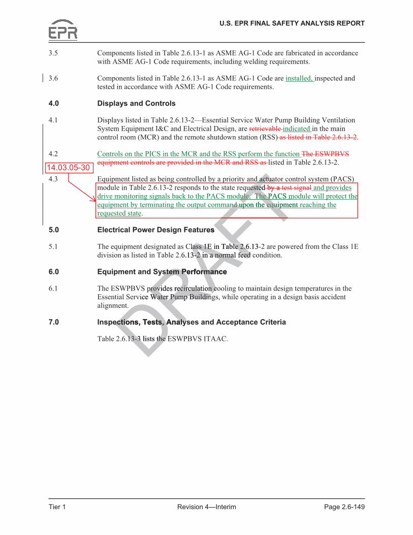
U.S. EPR FINAL SAFETY ANALYSIS REPORT
Tier 1 Revision 4—Interim Page 2.6-149
3.5 Components listed in Table 2.6.13-1 as ASME AG-1 Code are fabricated in accordance with ASME AG-1 Code requirements, including welding requirements.
3.6 Components listed in Table 2.6.13-1 as ASME AG-1 Code are installed, inspected and tested in accordance with ASME AG-1 Code requirements.
4.0 Displays and Controls
4.1 Displays listed in Table 2.6.13-2—Essential Service Water Pump Building Ventilation System Equipment I&C and Electrical Design, are retrievable indicated in the main control room (MCR) and the remote shutdown station (RSS) as listed in Table 2.6.13-2.
4.2 Controls on the PICS in the MCR and the RSS perform the function The ESWPBVS equipment controls are provided in the MCR and RSS as listed in Table 2.6.13-2.
4.3 Equipment listed as being controlled by a priority and actuator control system (PACS) module in Table 2.6.13-2 responds to the state requested by a test signal and provides drive monitoring signals back to the PACS module. The PACS module will protect the equipment by terminating the output command upon the equipment reaching the requested state.
5.0 Electrical Power Design Features
5.1 The equipment designated as Class 1E in Table 2.6.13-2 are powered from the Class 1E division as listed in Table 2.6.13-2 in a normal feed condition.
6.0 Equipment and System Performance
6.1 The ESWPBVS provides recirculation cooling to maintain design temperatures in the Essential Service Water Pump Buildings, while operating in a design basis accident alignment.
7.0 Inspections, Tests, Analyses and Acceptance Criteria
Table 2.6.13-3 lists the ESWPBVS ITAAC.
14.03.05-30
DRAFTres
Class 1E in Table 2.6.13-2lass 1E in Table 2.66.13-2 in a normal feed c-2 in a normal feed
stem Performance stem Performan
provides recirculation coprovides recirculation c
FTuesteduested
Tb
Ty
TTa
TTt
dule. The PACS mdule. The PTnd upon the equipment nd upon the equip
FTTd actuatd actu
vice Water Pump BuildinWater Pump Buildin
ections, Tests, Analysections, Tests, Analys
13-3 lists the E13-3 lists the
FT
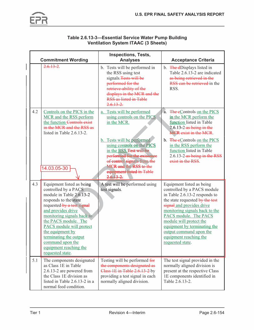
U.S. EPR FINAL SAFETY ANALYSIS REPORT
Tier 1 Revision 4—Interim Page 2.6-154
Table 2.6.13-3—Essential Service Water Pump Building Ventilation System ITAAC (3 Sheets)
Commitment Wording Inspections, Tests,
Analyses Acceptance Criteria 2.6.13-2. b. Tests will be performed in
the RSS using test signals.Tests will be performed for the retrieve-ability of the displays in the MCR and the RSS as listed in Table 2.6.13-2.
b. The dDisplays listed in Table 2.6.13-2 are indicated as being retrieved in the RSS can be retrieved in the RSS.
4.2 a. Tests will be performed using controls on the PICS in the MCR.
a. The cControls on the PICS in the MCR perform the function listed in Table 2.6.13-2 as being in the MCR exist in the MCR.
Controls on the PICS in the MCR and the RSS perform the function Controls exist in the MCR and the RSS as listed in Table 2.6.13-2.
b. Tests will be performed using controls on the PICS in the RSS.Test will be performed for the existence of control signals from the MCR and the RSS to the equipment listed in Table 2.6.13-2.
b. The cControls on the PICS in the RSS perform the function listed in Table 2.6.13-2 as being in the RSS exist in the RSS.
4.3 Equipment listed as being controlled by a PACS module in Table 2.6.13-2 responds to the state requested by a test signal and provides drive monitoring signals back to the PACS module. The PACS module will protect the equipment by terminating the output command upon the equipment reaching the requested state.
A test will be performed using test signals.
Equipment listed as being controlled by a PACS module in Table 2.6.13-2 responds to the state requested by the test signal and provides drive monitoring signals back to the PACS module. The PACS module will protect the equipment by terminating the output command upon the equipment reaching the requested state.
5.1 The components designated as Class 1E in Table 2.6.13-2 are powered from the Class 1E division as listed in Table 2.6.13-2 in a normal feed condition.
Testing will be performed for the components designated as Class 1E in Table 2.6.13-2 by providing a test signal in each normally aligned division.
The test signal provided in the normally aligned division is present at the respective Class 1E components identified in Table 2.6.13-2.
14.03.05-30
DRAReing CS CS
2.6.13-2 2.6.1e state e stat
st signalst signDck to ck to DA test will be peA test will be petest signals. test sRRRARAFTCS CS T
a. a Tin thTfunctiT2.6.13-22MCR MCRTTFTe performed performed
AFTntrols on the PICS n the PI
AFRSS.RSS
ATest will be ll be
AFrformed for the existence med for the existencAFof control signals from throl signals from th
RAMCR and the RSS to tMCR and the RSS to t
RAequipment listed inquipment lis
RA2.6.136.1RA-RA2.RAb. ThTFT
RFT
DRRA

U.S. EPR FINAL SAFETY ANALYSIS REPORT
Tier 1 Revision 4—Interim Page 2.7-3
3.18 Components listed in Table 2.7.1-1 as ASME Code Section III are fabricated, installed, and inspected in accordance with ASME Code Section III requirements.
3.19 Containment isolation valves are located close to containment penetrations.
4.0 I&C Design Features, Displays and Controls
4.1 Displays listed in Table 2.7.1-2—Component Cooling Water System Equipment I&C and Electrical Design are retrievable indicated in the main control room (MCR) and the remote shutdown station (RSS) as listed in Table 2.7.1-2.
4.2 Controls on the PICS in the MCR and the RSS perform the function The CCWS equipment controls are provided in the MCR and the RSS as listed in Table 2.7.1-2.
4.3 Equipment listed as being controlled by a priority and actuator control system (PACS) module in Table 2.7.1-2 responds to the state requested by a test signal and provides drive monitoring signals back to the PACS module. The PACS module will protect the equipment by terminating the output command upon the equipment reaching the requested state.
4.4 An interlock for the CCWS low flow condition automatically opens the low head safety injection (LHSI)/residual heat removal (RHR) heat exchanger (HX) inlet valve.
4.5 An interlock for the CCWS surge tank level of MIN3 automatically isolates the associated train common header switchover valves.
4.6 An interlock for the CCWS surge tank level of MIN4 automatically trips the associated CCWS pump and unlocks the common header switchover function to allow restoration of flow to the common users.
4.7 An interlock for the CCWS low surge tank level of MIN2 and a flow rate difference between the supply and return the supply flow rate to from the Nuclear Auxiliary Building (NAB) and the Radioactive Waste Building (RWB) is greater than the flow rate from NAB and RWB automatically isolates the non-safety-related branch.
4.8 Loss An interlock for the loss of one CCWS train initiates an automatic switchover to allow cooling of the common ‘a’ and/or ‘b’ headers.
4.9 Deleted.
4.10 An interlock for the CCWS train separation to RCP thermal barriers requires CIVs associated with one common header to be closed before the other common header CIVs can be opened.CCWS train separation to RCP thermal barriers is maintained by interlocks provided on the supply and return thermal barrier containment isolation valves. The interlocks require that CIVs associated with one common header be closed before the other common header CIVs can be opened.
4.11 An interlock for the Manual or automatic actuation of a CCWS pump, either automatically or manually automatically actuates the corresponding ESWS pump.
14.03.05-30
DRAFTeded by a bydd
Te. The PACSe. Th
Tupon the equipmenupon the eqTondition automatically opondition automatically opval (RHR) heat exchange(RHR) heat
rge tank level of MIN3 auge tank level of MINader switchover valves. switchover valves.
CWSCWS
RA surge tank level of surge tank leunlocks the common headunlocks the common
mon users. mon u
k for the CCWSk for the CCWS
DR low surgn the supply and return n the supply and return
DRthing (NAB) and the Radioing (NAB) and the Radio
AB and RWB AB a Dautomau
rlock forrlock forDf thf th
FT

U.S. EPR FINAL SAFETY ANALYSIS REPORT
Tier 1 Revision 4—Interim Page 2.7-25
Table 2.7.1-3—Component Cooling Water System ITAAC (10 Sheets)
Commitment Wording Inspections, Tests,
Analyses Acceptance Criteria 4.1 a. Tests will be performed in
the MCR using test signals. a. The dDisplays listed in
Table 2.7.1-2 are indicated as being retrieved in the MCR can be retrieved in the MCR.
Displays listed in Table 2.7.1-2 are indicated exist or can be retrieved in the MCR and the RSS as identified in Table 2.7.1-2.
b. Tests will be performed in the RSS using test signals.Tests will be performed for the retrieveability of the displays in the MCR or the RSS as listed in Table 2.7.1-2.
b. The dDisplays listed in Table 2.7.1-2 are indicated as being retrieved in the RSS can be retrieved in the RSS.
4.2 Controls on the PICS in the MCR and the RSS perform the function Controls exist in the MCR and the RSS as identified in Table 2.7.1-2.
a. Tests will be performed using controls on the PICS in the MCR.
a. The cControls on the PICS in the MCR perform the function listed in Table 2.7.1-2 as being in the MCR exist in the MCR.
b. Tests will be performed using controls on the PICS in the RSS.Tests will be performed for the existence of control signals from the MCR and the RSS to the equipment listed in Table 2.7.1-2.
b. The cControls on the PICS in the RSS perform the function listed in Table 2.7.1-2 as being in the RSS exist in the RSS.
4.3 Equipment listed as being controlled by a PACS module in Table 2.7.1-2 responds to the state requested by a test signal and provides drive monitoring signals back to the PACS module. The PACS module will protect the equipment by terminating the output command upon the equipment reaching the requested state.
Deleted. Equipment listed as being controlled by a PACS module in Table 2.7.1-2 responds to the state requested by the test signal and provides drive monitoring signals back to the PACS module. The PACS module will protect the equipment by terminating the output command upon the equipment reaching the requested state.
14.03.05-30 DRAFTR or the or th Table able
FTRS
FTbe performed performed
AFTontrols on the PICS on the P
AFMCR.MC
Aa. TFTFTFTFT
b. Tests will be performb. Tests will be p
RAusing controls on sing control
RAin the RSS.in the RSRATesTeRAperformed fperformed f
DRooDRf controRMCR MCDReququD2DRDRbeing being DDDDDR

U.S. EPR FINAL SAFETY ANALYSIS REPORT
Tier 1 Revision 4—Interim Page 2.7-63
3.5 Pressure boundary welds on components listed in Table 2.7.5-1 as ASME Code Section III are in accordance withmeet ASME Code Section III non-destructive examination requirements.
3.6 Components listed in Table 2.7.5-1 as ASME Code Section III retain their pressure boundary integrity at their design pressure.
3.7 Components listed in Table 2.7.5-1 as ASME Code Section III are fabricated, installed, and inspected in accordance with ASME Code Section III requirements.
3.8 Containment isolation valves are located close to containment penetrations.
3.9 FWDS piping between containment isolation valves is reconciled in accordance with an ASME Code Section III Design Report.
3.10 FWDS piping between containment isolation valves is fabricated, installed and inspected in accordance with ASME Code Section III requirements.
3.11 Pressure boundary welds in FWDS piping between containment isolation valves meet ASME Code Section III non-destructive examination requirements.
3.12 FWDS piping between containment isolation valves retains pressure boundary integrity at design pressure.
4.0 I&C Design Features, Displays and Controls
4.1 Displays listed in Table 2.7.5-2—Fire Water Distribution System Equipment I&C and Electrical Design are retrievable indicated in the main control room (MCR) and the remote shutdown station (RSS) as listed in Table 2.7.5-2.
4.2 Controls on the PICS in the MCR and the RSS perform the function The FWDS equipment controls are provided in the MCR and the RSS as listed in Table 2.7.5-2.
4.3 Equipment listed as being controlled by a priority and actuator control system (PACS) module in Table 2.7.5-2 responds to the state requested by a test signal and provides drive monitoring signals back to the PACS module. The PACS module will protect the equipment by terminating the output command upon the equipment reaching the requested state.
4.4 The as-builtlocation of the fire water distribution system equipment is consistent with the post-fire safe shutdown analysis.
5.0 Electrical Power Design Features
5.1 The components designated as Class 1E in Table 2.7.5-2 are powered from the Class 1E division as listed in Table 2.7.5-2 in a normal or alternate feed condition.
5.2 Valves listed in Table 2.7.5-2 fail as-is on loss of power.
14.03.05-30 DRDRAFTs fabrics fab
Tements.emen
Tetween containment isoletween containme
FTxamination requirementsxamination requireme
FTisolation valves retains plation valve
AFTisplays and Controls ays and Controls
le 2.7.5-2—Fire Water Dle 2.7.5-2—Fire Wre re retrievable retrievabl
RAindicated icat
RAinn station (RSS)station (RSS) as listed i as listed RA
n the PICS in the MCR ann the PICS in th
DRent controls are provided ent controls are provid
DRment listed as being cment listed as bein
n Table 2.7.5-2 n Table 2.7.5-2ring signring signDermermD
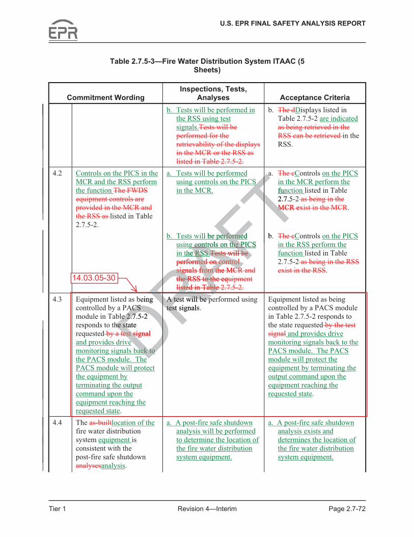
U.S. EPR FINAL SAFETY ANALYSIS REPORT
Tier 1 Revision 4—Interim Page 2.7-72
Table 2.7.5-3—Fire Water Distribution System ITAAC (5 Sheets)
Commitment Wording Inspections, Tests,
Analyses Acceptance Criteria b. Tests will be performed in
the RSS using test signals.Tests will be performed for the retrievability of the displays in the MCR or the RSS as listed in Table 2.7.5-2.
b. The dDisplays listed in Table 2.7.5-2 are indicated as being retrieved in the RSS can be retrieved in the RSS.
4.2 Controls on the PICS in the MCR and the RSS perform the function The FWDS equipment controls are provided in the MCR and the RSS as listed in Table 2.7.5-2.
a. Tests will be performed using controls on the PICS in the MCR.
a. The cControls on the PICS in the MCR perform the function listed in Table 2.7.5-2 as being in the MCR exist in the MCR.
b. Tests will be performed using controls on the PICS in the RSS.Tests will be performed on control signals from the MCR and the RSS to the equipment listed in Table 2.7.5-2.
b. The cControls on the PICS in the RSS perform the function listed in Table 2.7.5-2 as being in the RSS exist in the RSS.
4.3 Equipment listed as being controlled by a PACS module in Table 2.7.5-2 responds to the state requested by a test signal and provides drive monitoring signals back to the PACS module. The PACS module will protect the equipment by terminating the output command upon the equipment reaching the requested state.
A test will be performed using test signals.
Equipment listed as being controlled by a PACS module in Table 2.7.5-2 responds to the state requested by the test signal and provides drive monitoring signals back to the PACS module. The PACS module will protect the equipment by terminating the output command upon the equipment reaching the requested state.
4.4 The as-builtlocation of the fire water distribution system equipment is consistent with the post-fire safe shutdown analysesanalysis.
a. A post-fire safe shutdown analysis will be performed to determine the location of the fire water distribution system equipment.
a. A post-fire safe shutdown analysis exists and determines the location of the fire water distribution system equipment.
14.03.05-30
DRARbeing ACS ACS
e 2.7.5-2 e 2.7he state he st
test signaltest si Deeack to ack to D
A test will be pA test will be ptest signals. test RRRAFT
SS
Taa
TfunT2.7.5-MCR exMTFTill be performed erformed
AFg controls on the PICS g controls on the PI
AFthe RSS.e RSS.ATests will be Tests will be AFperformed on cmed on c
RAontrol ontrol Asignals from the MCRsignals from the MCR
RAthe RSS to the equthe RSS to th
RAlisted in Table 2isted in TableRAb.
RRFT
RADRRA

U.S. EPR FINAL SAFETY ANALYSIS REPORT
Tier 1 Revision 4—Interim Page 2.7-80
3.6 Components listed in Table 2.7.11-1 as ASME Code Section III are fabricated reconciled in accordance with ASME Code Section III design requirements.
3.7 Pressure boundary welds on components listed in Table 2.7.11-1 as ASME Code Section III are in accordance with meet ASME Code Section III non-destructive examinations requirements.
3.8 Components listed in Table 2.7.11-1 as ASME Code Section III retain pressure boundary integrity at design pressure.
3.9 Deleted.
3.10 Deleted.
3.11 Deleted.
3.12 ESWS piping shown as ASME Code Section III on Figure 2.7.11-1 is designed in accordance with ASME Code Section III requirements.
3.13 ESWS piping shown as ASME Code Section III on Figure 2.7.11-1 is installed reconciled in accordance with an ASME Code Section III Design Report.
3.14 Pressure boundary welds in ESWS piping shown as ASME Code Section III on Figure 2.7.11-1 are in accordance withmeet ASME Code Section III.
3.15 ESWS piping shown as ASME Code Section III on Figure 2.7.11-1 retains pressure boundary integrity at design pressure.
3.16 ESWS piping shown as ASME Code Section III on Figure 2.7.11-1 is fabricated, installed, and inspected in accordance with ASME Code Section III requirements.
3.17 Components listed in Table 2.7.11-1 as ASME Code Section III are fabricated, installed, and inspected in accordance with ASME Code Section III requirements.
3.18 The UHS fans are capable of withstanding the effects of tornado including differential pressure effects, overspeed, and the impact of differential pressure effects on other equipment located within the cooling tower structure (e.g., capability to function, potential to become missile/debris hazard).
4.0 I&C Design Features, Displays and Controls
4.1 Displays listed in Table 2.7.11-2— Essential Service Water System Equipment I&C and Electrical Design are retrievable indicated in the main control room (MCR) and the remote shutdown station (RSS) as listed in Table 2.7.11-2.
4.2 The ESWS equipment controls are provided in the MCR and the RSS as Controls on the PICS in the MCR and the RSS perform the function listed in Table 2.7.11-2.
4.3 Equipment listed as being controlled by a priority and actuator control system (PACS) module in Table 2.7.11-2 responds to the state requested by a test signal and provides drive monitoring signals back to the PACS module. The PACS module will protect the
14.03.05-30
DRAFTn Figure 2.7.n Figu
ements. ements.
ion III on Figure 2.7.11-1ion III on Figure 2.7.1ction III Design Report. ction III Design Report.
S piping shown as ASMEshownhmeetmeet
A ASME Code Sectio ASME Code tt
ASME Code Section III oode Section III odesign pressure. design pressure.
own as ASME Code Sectown as ASME Code Seinspected in accordance wected in accordance w
nents listed in Table 2.7.1nents listed in Table 2nspectednspec D in accordance wcordance wd
fans are capablfans are capabects, oversects, overs
tedted

U.S. EPR FINAL SAFETY ANALYSIS REPORT
Tier 1 Revision 4—Interim Page 2.7-81
equipment by terminating the output command upon the equipment reaching the requested state.
4.4 If An interlock for failure of one ESWS pump (30PEB10/20/30/40 AP001) fails during normal operation, results in a switchover to the other ESWS train is carried out automatically for the entire cooling train and is initiated by the CCWS Switchover sequence.
4.5 An interlock for a spurious closure of the ESWS pump discharge valve (30PEB10/20/30/40 AA005) results in a switchover to the other ESWS train automatically for the entire cooling train and is initiated by the CCWS Switchover sequence.
4.6 Deleted.
4.7 Deleted.
5.0 Electrical Power Design Features
5.1 The components designated as Class 1E in Table 2.7.11-2 are powered from the Class 1E division as listed in Table 2.7.11-2 in a normal or alternate feed condition.
5.2 Valves listed in Table 2.7.11-2 fail as-is on loss of power.
5.3 Deleted.
5.4 Items identified in Table 2.7.11-2 as “Dedicated” ESWS motor-operated components (including Division 4 cooling tower fans) are capable of being supplied by a SBODG.
6.0 Environmental Qualifications
6.1 Deleted.
7.0 Equipment and System Performance
7.1 The ESWS UHS as listed in Table 2.7.11-1 has the capacity to remove the total Max Heat Load from the CCWS and EDG heat exchangers, and the ESWPBVS room cooler, and the ESW pump mechanical work.
7.2 The pumps listed in Table 2.7.11-1 have sufficient net positive suction head available (NPSHA).
7.3 Class 1E valves listed in Table 2.7.11-2 can perform the will function to change position as listed in Table 2.7.11-1 under system operating conditions.
7.4 The ESWS provides for flow testing of the ESWS pumps during plant operation.
7.5 Deleted.
7.6 The ESWS delivers water to the CCWS and EDG heat exchangers and the ESWPBVS room cooler.
14.03.05-30
DRAFTn Table 2.7.11-2 are powen Table 2.7.11-2 are ponormal or alternate feed normal or alternate feed
il as-is on loss of power. n loss
ble 2.7.11-2 as “Dedicatedble 2.7.11-2 as “De 4 cooling tower fans) are 4 cooling tower fan
ntal Qualifications Qualifications
ment and Systemment and Syst
UHS as lisUHS as lisCCWCCW

U.S. EPR FINAL SAFETY ANALYSIS REPORT
Tier 1 Revision 4—Interim Page 2.7-105
Table 2.7.11-3—Essential Service Water System ITAAC (10 Sheets)
Commitment Wording Inspections, Tests, Analyses Acceptance Criteria
b. Tests will be performed using controls on the PICS in the RSS.Tests will be performed for the existence of control signals from the MCR and the RSS to the equipment listed in Table 2.7.11-2.
b. The cControls on the PICS in the RSS perform the function listed in Table 2.7.11-2 as being in the RSS exist in the RSS.
4.3 Equipment listed as being controlled by a PACS module in Table 2.7.11-2 responds to the state requested by a test signal and provides drive monitoring signals back to the PACS module. The PACS module will protect the equipment by terminating the output command upon the equipment reaching the requested state.
A test will be performed using test signals.
Equipment listed as being controlled by a PACS module in Table 2.7.11-2 responds to the state requested by the test signal and provides drive monitoring signals back to the PACS module. The PACS module will protect the equipment by terminating the output command upon the equipment reaching the requested state.
4.4 If An interlock for failure of one ESWS pump (30PEB10/20/30/40 AP001) fails during normal operation, results in a switchover to the other ESWS train is carried out automatically for the entire cooling train and is initiated by the CCWS Switchover sequence.
Tests will be performed using test signals to verify the interlock.
The following interlock responds as specified below when activated by a test signal:
If one ESWS pump (30PEB10/20/30/40 AP001) fails during normal operation, a switchover to the other ESWS train is carried out automatically for the entire cooling train and is initiated by the CCWS Switchover sequence.
14.03.05-30
DRof of RAP001) AP001)al al
lts inlts in D a e other e oth
ied out ied ouDentire entire DatedatedDRATests will be perforts will be perftest signalstest signalsRAFT
coin Tabthe statetsignalsignT andTmonitormonitTPACCTm
RFT
to ve to veRinterlockinte
DR. RRRADRRA

U.S. EPR FINAL SAFETY ANALYSIS REPORT
Tier 1 Revision 4—Interim Page 2.8-10
3.5 Components listed in Table 2.8.2-1 as ASME Code Section III are reconciledfabricated in accordance with ASME Code Section III requirements.
3.6 Pressure boundary welds on components listed in Table 2.8.2-1 as ASME Code Section III are in accordance withmeet ASME Code Section III non-destructive examination requirements.
3.7 Components listed in Table 2.8.2-1 as ASME Code Section III retain pressure boundary integrity at design pressure.
3.8 MSS piping shown as ASME Code Section III on Figure 2.8.2-1 areis designed in accordance with ASME Code Section III requirements.
3.9 MSS piping shown as ASME Code Section III on Figure 2.8.2-1 areis installed reconciled in accordance with an ASME Code Section III Design Report.
3.10 Pressure boundary welds in MSS piping shown as ASME Code Section III on Figure 2.8.2-1 are in accordance withmeet ASME Code Section III requirements.
3.11 MSS piping shown as ASME Code Section III on Figure 2.8.2-1 retains pressure boundary integrity at design pressure.
3.12 MSS piping shown as ASME Code Section III on Figure 2.8.2-1 are is fabricated, installed, and inspected in accordance with ASME Code Section III requirements.
3.13 Components listed in Table 2.8.2-1 as ASME Code Section III are fabricated, installed, and inspected in accordance with ASME Code Section III requirements.
4.0 Instrumentation and Controls (I&C) Design Features, Displays, and Controls
4.1 Displays listed in Table 2.8.2-2—MSS Equipment I&C and Electrical Design are retrievable indicated in the main control room (MCR) and the remote shutdown station (RSS) as listed in Table 2.8.2-2.
4.2 Controls on the PICS in the MCR and the RSS perform the function The MSS equipment controls are provided in the MCR and the RSS as listed in Table 2.8.2-2.
4.3 Equipment listed as being controlled by a priority and actuator control system (PACS) module in Table 2.8.2-2 responds to the state requested by a test signal and provides drive monitoring signals back to the PACS module. The PACS module will protect the equipment by terminating the output command upon the equipment reaching the requested state.
5.0 Electrical Power Design Features
5.1 The components designated as Class 1E in Table 2.8.2-2 are powered from the Class 1E division as listed in Table 2.8.2-2 in a normal or alternate feed condition.
5.2 Each main steam relief isolation valve fails closed on loss of electric power. to the valve actuator.
14.03.05-30 iiDRAFTIIII
ASME CodeASMe Section IIIe Section I requirTon III on Figure 2.8.2-1 reon III on Figure 2.8.2-1
de Section III on Figure 2n III oordance with ASME Coderdance with ASME
ble 2.8.2-1 as ASME Cod-1 as ASME Cordance with ASME Code rdance with ASME
on and Controls (I&C)n and Controls (I&C
s listed in Table 2.8.2-2s listed in Table 2.8.2- —Rvable vable Dindicated dDin the in mamaRas listed in Table as listed in TableD2.8Dthe PICS the PICS DvidvidD

U.S. EPR FINAL SAFETY ANALYSIS REPORT
Tier 1 Revision 4—Interim Page 2.8-27
Table 2.8.2-3—Main Steam System ITAAC (7 Sheets)
Commitment Wording Inspections, Tests,
Analyses Acceptance Criteria 4.2 Controls on the PICS in the
MCR and the RSS perform the function listed Controls exist in the MCR and the RSS as identified in Table 2.8.2-2.
a. Tests will be performed using controls on the PICS in the MCR.
a. The cControls on the PICS in the MCR perform the function listed in Table 2.8.2-2 as being in the MCR exist in the MCR.
b. Tests will be performed using controls on the PICS in the RSS.Tests will be performed for the existence of control signals from the MCR and the RSS to the equipment listed in Table 2.8.2-2.
b. The cControls on the PICS in the RSS perform the function listed in Table 2.8.2-2 as being in the RSS exist in the RSS.
4.3 Equipment listed as being controlled by a PACS module in Table 2.8.2-2 responds to the state requested by a test signal and provides drive monitoring signals back to the PACS module. The PACS module will protect the equipment by terminating the output command upon the equipment reaching the requested state.
A test will be performed using test signals.
Equipment listed as being controlled by a PACS module in Table 2.8.2-2 responds to the state requested by the test signal and provides drive monitoring signals back to the PACS module. The PACS module will protect the equipment by terminating the output command upon the equipment reaching the requested state.
5.1 The components designated as Class 1E in Table 2.8.2-2 are powered from the Class 1E division as listed in Table 2.8.2-2 in a normal or alternate feed condition.
a. Testing will be performed for components designated as Class 1E in Table 2.8.2-2 by providing a test signal in each normally aligned division.
a. The test signal provided in the normally aligned division is present at the respective Class 1E components identified in Table 2.8.2-2.
b. Testing will be performed for components designated as Class 1E in Table 2.8.2-2 by providing a test signal in each division with the alternate feed aligned to the divisional pair.
b. The test signal provided in each division with the alternate feed aligned to the divisional pair is present at the respective Class 1E components identified in Table 2.8.2-2.
14.03.05-30
DRAFTe e he he TTable Table
FT2existTFT
ect
Dutput utput
Dthe the Dhing the hing th D
erformed using formed using EquipmcontinFTFTFT
DRFT
nated nated 22DDDDDRAFT

U.S. EPR FINAL SAFETY ANALYSIS REPORT
Tier 1 Revision 4—Interim Page 2.8-33
3.5 Components listed in Table 2.8.6-1 as ASME Code Section III are designed in accordance with ASME Code Section III requirements.
3.6 Components listed in Table 2.8.6-1 as ASME Code Section III are fabricated reconciled in accordance with ASME Code Section III design requirements.
3.7 Pressure boundary welds on components listed in Table 2.8.6-1 as ASME Code Section III are in accordance withmeet ASME Code Section III non-destructive examination requirements.
3.8 Components listed in Table 2.8.6-1 as ASME Code Section III retain pressure boundary integrity at design pressure.
3.9 MFWS piping shown as ASME Code Section III on Figure 2.8.6-1 is designed in accordance with ASME Code Section III requirements.
3.10 MFWS piping shown as ASME Code Section III on Figure 2.8.6-1 is installed reconciled in accordance with an ASME Code Section III Design Report.
3.11 Pressure boundary welds in MFWS piping shown as ASME Code Section III on Figure 2.8.6-1 are in accordance withmeet ASME Code Section III requirements.
3.12 MFWS piping shown as ASME Code Section III on Figure 2.8.6-1 retains pressure boundary integrity at design pressure.
3.13 MFWS piping shown as ASME Code Section III on Figure 2.8.6-1 is fabricated, installed, and inspected in accordance with ASME Code Section III requirements.
3.14 Components listed in Table 2.8.6-1 as ASME Code Section III are fabricated, installed, and inspected in accordance with ASME Code Section III requirements.
4.0 Instrumentation and Control (I&C) Design Features, Displays, and Controls
4.1 Displays listed in Table 2.8.6-2—MFWS Equipment I&C and Electrical Design are retrievable indicated in the main control room (MCR) as listed in Table 2.8.6-2.
4.2 Controls on the PICS in the MCR and the RSS perform the function The MFWS equipment controls are provided in the MCR as listed in Table 2.8.6-2.
4.3 Equipment listed as being controlled by a priority and actuator control system (PACS) module in Table 2.8.6-2 responds to the state requested by a test signal and provides drive monitoring signals back to the PACS module. The PACS module will protect the equipment by terminating the output command upon the equipment reaching the requested state.
5.0 Electrical Power Design Features
5.1 The components designated as Class 1E in Table 2.8.6-2 are powered from the Class 1E division as listed in Table 2.8.6-2 in a normal or alternate feed condition.
5.2 The main feedwater full load isolation valves (MFWFLIVs) fail closed on loss of hydraulic pressure in each redundant dump line.to the valve actuator.
14.03.05-30
on Figure 2.8on FigDesign Report. Design Rep
g shown as ASME Code Sg shown as ASME CodME Code Section IIIME Code Sec requequT
Code Section III on Figuretion IIressure. essure.
ASME Code Section III oCode Section III d in accordance with ASMd in accordance w
ed in Table 2.8.6-1 as ASed in Table 2.8.6-1 as Ain accordance with ASMccordance with ASM
mentation and Contromentation and Con
ys listed in Table 2.8ys listed in Table ee Dindicated indicated Din thin
PICPIC

U.S. EPR FINAL SAFETY ANALYSIS REPORT
Tier 1 Revision 4—Interim Page 2.8-44
Table 2.8.6-3— Main Feedwater System ITAAC (5 Sheets)
Commitment Wording Inspections, Tests,
Analyses Acceptance Criteria 4.2 Controls on the PICS in the
MCR and the RSS perform the function listed Controls exist in the MCR as identified in Table 2.8.6-2.
a. Tests will be performed using controls on the PICS in the MCR.
a. The cControls on the PICS in the MCR perform the function listed in Table 2.8.6-2 as being in the MCR exist in the MCR.
b. Tests will be performed using controls on the PICS in the RSS.Tests will be performed for the existence of control signals from the MCR to the equipment listed in Table 2.8.6-2.
b. Controls on the PICS in the RSS perform the function listed in Table 2.8.6-2.
4.3 Equipment listed as being controlled by a PACS module in Table 2.8.6-2 responds to the state requested by a test signal and provides drive monitoring signals back to the PACS module. The PACS module will protect the equipment by terminating the output command upon the equipment reaching the requested state.
A test will be performed using test signals.
Equipment listed as being controlled by a PACS module in Table 2.8.6-2 responds to the state requested by the test signal and provides drive monitoring signals back to the PACS module. The PACS module will protect the equipment by terminating the output command upon the equipment reaching the requested state.
5.1 The components designated as Class 1E in Table 2.8.6-2 are powered from the Class 1E division as listed in Table 2.8.6-2 in a normal or alternate feed condition.
a. Testing will be performed for components designated as Class 1E in Table 2.8.6-2 by providing a test signal in each normally aligned division.
a. The test signal provided in the normally aligned division is present at the respective Class 1E component identified in Table 2.8.6-2.
b. Testing will be performed for components designated as Class 1E in Table 2.8.6-2 by providing a test signal in each division with the alternate feed aligned to the divisional pair.
b. The test signal provided in each division with the alternate feed aligned to the divisional pair is present at the respective Class 1E component identified in Table 2.8.6-2.
14.03.05-30
DRAFT.. TFTing the ing the
Dee D. .
med using med u Equipment Equipmcontrolletrollin TabstaFTFTFT
DRFT
s designated s desigle 2.8.6-2 le 2.8.6-2
Class Class
a. Ta.DDDDDRAFT

U.S. EPR FINAL SAFETY ANALYSIS REPORT
Tier 1 Revision 4—Interim Page 2.8-46
3.6 Pressure boundary welds on components listed in Table 2.8.7-1 as ASME Code Section III are in accordance withmeet ASME Code Section III non-destructive examination requirements.
3.7 Components listed in Table 2.8.7-1 as ASME Code Section III retain pressure boundary integrity at design pressure.
3.8 SGBS piping shown as ASME Code Section III on Figure 2.8.7-1 is designed in accordance with ASME Code Section III requirements.
3.9 SGBS piping shown as ASME Code Section III on Figure 2.8.7-1 is installed reconciled in accordance with an ASME Code Section III Design Report.
3.10 Pressure boundary welds in SGBS piping shown as ASME Code Section III on Figure 2.8.7-1 are in accordance withmeet ASME Code Section III requirements.
3.11 SGBS piping shown as ASME Code Section III on Figure 2.8.7-1 retains pressure boundary integrity at design pressure.
3.12 SGBS piping shown as ASME Code Section III on Figure 2.8.7-1 is fabricated, installed, and inspected in accordance with ASME Code Section III requirements.
3.13 Components listed in Table 2.8.7-1 as ASME Code Section III are fabricated, installed, and inspected in accordance with ASME Code Section III requirements.
3.14 Containment isolation valves are located close to containment penetrations.
4.0 Instrumentation and Controls (I&C) Design Features, Displays, and Controls
4.1 Displays listed in Table 2.8.7-2—SGBS Equipment I&C and Electrical Design are retrievable indicated in the main control room (MCR) and the remote shutdown station (RSS) as listed in Table 2.8.7-2.
4.2 Controls on the PICS in the MCR and the RSS perform the function SGBS equipment controls are provided in the MCR and the RSS as listed in Table 2.8.7-2.
4.3 Equipment listed as being controlled by a priority and actuator control system (PACS) module in Table 2.8.7-2 responds to the state requested by a test signal and provides drive monitoring signals back to the PACS module. The PACS module will protect the equipment by terminating the output command upon the equipment reaching the requested state.
4.4 Interlocks for the SGBS blowdown isolation valves listed in Table 2.8.7-2 result in closure for of the affected SG under the following signals:
• EFW actuation signal, or
• High main steam activity signal with a partial cooldown signal, or,
• High SG level signal with a partial cooldown signal, or
14.03.05-30 DrovidedrovidedDDR)) as listed in Table 2.8.7 as listed in Table 2.8.7DRAFTn n
n Figure 2.8.7n Figu
ion III on Figure 2.8.7-1 iion III on Figure 2.8.7-E Code Section III requirE Code Section III requir
-1 as ASME Code SectionME Coith ASME Code Section th ASME Code Sec
alves are located close to clocated close to
RAand Controls (I&C) Deand Controls (I&C
sted in Table 2.8.7-2sted in Table 2.8 —RSGRble ble
Dindicated indicated
DRin the in the main maRas listed in Table 2 8 7as listed in Table 2 8 7DRon the PICS in on the PICS inDprovidedprovidedD

U.S. EPR FINAL SAFETY ANALYSIS REPORT
Tier 1 Revision 4—Interim Page 2.8-58
Table 2.8.7-3—Steam Generator Blowdown System ITAAC (6 Sheets)
Commitment Wording Inspections, Tests,
Analyses Acceptance Criteria 4.2 Controls on the PICS in the
MCR and the RSS perform the function listed Controls exist in the MCR and the RSS as identified in Table 2.8.7-2.
a. Tests will be performed using controls on the PICS in the MCR.
a. The cControls on the PICS in the MCR perform the function listed in Table 2.8.7-2 as being in the MCR exist in the MCR.
b. Tests will be performed using controls on the PICS in the RSS.Tests will be performed for the existence of control signals from the MCR and the RSS to the equipment listed in Table 2.8.7-2.
b. The cControls on the PICS in the RSS perform the function listed in Table 2.8.7-2 as being in the RSS exist in the RSS.
4.3 Equipment listed as being controlled by a PACS module in Table 2.8.7-2 responds to the state requested by a test signal and provides drive monitoring signals back to the PACS module. The PACS module will protect the equipment by terminating the output command upon the equipment reaching the requested state.
A test will be performed using test signals.
Equipment listed as being controlled by a PACS module in Table 2.8.7-2 responds to the state requested by the test signal and provides drive monitoring signals back to the PACS module. The PACS module will protect the equipment by terminating the output command upon the equipment reaching the requested state.
14.03.05-30
DRDRRhe
RRS RDRDRnating th
DRDRupon the
DRDRching DDDRAFTAFTrformed
AFnals. TFTFTTTFTT
in
TTTstence TTom the TFTSS to
FTFTsted in
FTFTTTTTTTTAFT
DDRD
T
DRAFT
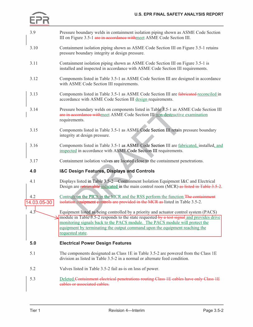
U.S. EPR FINAL SAFETY ANALYSIS REPORT
Tier 1 Revision 4—Interim Page 3.5-2
3.9 Pressure boundary welds in containment isolation piping shown as ASME Code Section III on Figure 3.5-1 are in accordance withmeet ASME Code Section III.
3.10 Containment isolation piping shown as ASME Code Section III on Figure 3.5-1 retains pressure boundary integrity at design pressure.
3.11 Containment isolation piping shown as ASME Code Section III on Figure 3.5-1 is installed and inspected in accordance with ASME Code Section III requirements.
3.12 Components listed in Table 3.5-1 as ASME Code Section III are designed in accordance with ASME Code Section III requirements.
3.13 Components listed in Table 3.5-1 as ASME Code Section III are fabricated reconciled in accordance with ASME Code Section III design requirements.
3.14 Pressure boundary welds on components listed in Table 3.5-1 as ASME Code Section III are in accordance withmeet ASME Code Section III non-destructive examination requirements.
3.15 Components listed in Table 3.5-1 as ASME Code Section III retain pressure boundary integrity at design pressure.
3.16 Components listed in Table 3.5-1 as ASME Code Section III are fabricated, installed, and inspected in accordance with ASME Code Section III requirements.
3.17 Containment isolation valves are located close to the containment penetrations.
4.0 I&C Design Features, Displays and Controls
4.1 Displays listed in Table 3.5-2—Containment Isolation Equipment I&C and Electrical Design are retrievable indicated in the main control room (MCR) as listed in Table 3.5-2.
4.2 Controls on the PICS in the MCR and the RSS perform the function The containment isolation equipment controls are provided in the MCR as listed in Table 3.5-2.
4.3 Equipment listed as being controlled by a priority and actuator control system (PACS) module in Table 3.5-2 responds to the state requested by a test signal and provides drive monitoring signals back to the PACS module. The PACS module will protect the equipment by terminating the output command upon the equipment reaching the requested state.
5.0 Electrical Power Design Features
5.1 The components designated as Class 1E in Table 3.5-2 are powered from the Class 1E division as listed in Table 3.5-2 in a normal or alternate feed condition.
5.2 Valves listed in Table 3.5-2 fail as-is on loss of power.
5.3 Deleted.Containment electrical penetrations routing Class 1E cables have only Class 1E cables or associated cables.
14.03.05-30 DRAFTble 3.5-ble 3.
II II non-destrunon
TME Code Section III retainME Code Section III ret
as ASME Code Section E CodASME Code Section III reSME Code Section
alves are located close to tlocated close to
ures, Displays and Coures, Displays an
d in Table 3.5-2—ContaiTable 3.5-2—Contairetrievable retrievable
DRindicated indi
DRin th
ols on the PICS in the Mols on the PICS in the MDon eqon eq Duipment controluipment conDisted as beisted as bee 3.e 3.D

U.S. EPR FINAL SAFETY ANALYSIS REPORT
Tier 1 Revision 4—Interim Page 3.5-23
Table 3.5-3—Containment Isolation ITAAC (8 Sheets)
Commitment Wording Inspections, Tests,
Analyses Acceptance Criteria 4.1 Displays listed in Table 3.5-2
are indicated exist or can be retrieved in the MCR as identified in Table 3.5-2.
a. Tests will be performed using controls on the PICS in the MCR.
b. Tests will be performed using controls on the PICS in the RSS.Inspections will be performed for the existence or retrievability of the displays in the MCR as listed in Table 3.5-2.
a. Controls on the PICS in the MCR perform the function listed in Table 3.5-2.
b. Controls on the PICS in the RSS perform the function listed in Table 3.5-2.The displays listed in Table 3.5-2 as being retrieved in the MCR can be retrieved in the MCR.
4.2 Controls on the PICS in the MCR and the RSS perform the function The containment isolation equipment controls are provided in the MCR as listed in Table 3.5-2.
Tests will be performed for the existence of control signals from the MCR to the equipment listed in Table 3.5-2.
The containment isolation equipment controls are provided in the MCR as listed in Table 3.5-2.
4.3 Equipment listed as being controlled by a PACS module in Table 3.5-2 responds to the state requested by a test signal and provides drive monitoring signals back to the PACS module. The PACS module will protect the equipment by terminating the output command upon the equipment reaching the requested state.
A test will be performed using test signals.
Equipment listed as being controlled by a PACS module in Table 3.5-2 responds to the state requested by the test signal and provides drive monitoring signals back to the PACS module. The PACS module will protect the equipment by terminating the output command upon the equipment reaching the requested state.
5.1 The components designated as Class 1E in Table 3.5-2 are powered from the Class 1E division as listed in Table 3.5-2 in a normal or alternate feed condition.
a. Testing will be performed for components designated as Class 1E in Table 3.5-2 by providing a test signal in each normally aligned division.
a. The test signal provided in the normally aligned division is present at the respective Class 1E components identified in Table 3.5-2.
b. Testing will be performed for components designated as Class 1E in Table 3.5-2 by providing a test signal in each division with the alternate feed aligned to the divisional pair.
b. The test signal provided in each division with the alternate feed aligned to the divisional pair is present at the respective Class 1E components identified in Table 3.5-2.
14.03.05-30
DDRRRDRDRDRThe
DDRwill protect the
DRDRterminating the DAFTTTTTTTAFTFTed for the
FTl sign
FTo the
AFTed in Table 3FTTTequTproviTTFT
Dnd upo DDng theDDDRAAFwill be performed us
RAFals. AFDRDtDDRAF

U.S. EPR FINAL SAFETY ANALYSIS REPORT
Tier 2 Revision 4—Interim Page 7.1-47
safety-related systems implement error detection algorithms to detect and accommodate failures.
7.1.1.6.5 Priority
The U.S. EPR I&C design allows for multiple I&C systems to send requests to a given actuator. To make certain that each individual actuator executes the proper action for the given plant condition, priority management rules for the PACS are provided. The following systems inputs to the PACS are listed in order of priority:
� PS/DAS.
� DAS.
� SAS.
� SICS.
� PAS.
The DAS is given a higher priority than the SAS because it is a functional substitute to the PS and is needed at this level of priority to verify proper operation of SAS functions on a SWCCF of the PS.
During normal operation, the operational I&C disable switch on the SICS is set so that the PAS can send commands to the PACS. In this configuration, automatic commands from the PAS override manual commands from the SICS because of the nature of the manual control logic in the PACS. If the operational I&C disable switch is set to DISABLE by the operator, the PAS input will be disabled (i.e., the input signals from the PAS to the communications module will be blocked from being sent to the priority module), providing the priority of the SICS manual commands. The operational I&C disable switch disables PAS inputs, all other PACS inputs remain operational.
7.1.2 Identification of Safety Criteria
Table 7.1-2—I&C System Requirements Matrix, shows the I&C system requirements matrix which details the regulatory requirements for the I&C systems of the U.S. EPR.
The U.S. EPR is designed in accordance with IEEE Std 603-1998 (Reference 1). Refer to Section 7.1.2.6 for an explanation for using IEEE Std 603-1998 in lieu of IEEE Std 603-1991 per the alternative request in Reference 45.
The following I&C systems are within the scope of the protection system as defined in IEEE Std 603-1998 (Reference 1):
� Protection system.
14.03.05-30
DRAFTthan the SAS because it an the SAS bel of priority to verify prel of priority to
e PS.PS.
ion, the operational on, the operationa I&C &Commands to the PACS. Iommands to the PA
verride manual commanerride manual commanrol logic in the PACS. Ifgic in the PACS. If
E by the operator, the PAE by the operator, AS to the communicationAS to the communicatiole), providing the priole), providing the
witch disables Pwitch disables
ofof

U.S. EPR FINAL SAFETY ANALYSIS REPORT
Tier 2 Revision 4—Interim Page 7.8-2
7.8.1.1.2 Deleted
7.8.1.1.3 Diverse Actuation System
The DAS executes manual functions initiated from SICS and automatic functions to mitigate an ATWS or SWCCF of the PS. The DAS is diverse from the PS.
The DAS executes the automatic RT, ESF actuation, and alarm and display functions listed in Section 7.8.1.2. Sensor information is acquired by the DAS from the signal conditioning and distribution system (SCDS) using a hardwired signal that is not affected by a SWCCF. This path is described in Section 7.1.1.6. The DAS also processes the manual, system level actuation of critical safety functions as described in Section 7.8.1.2.3.
For RT functions, outputs from the DAS are sent to the shunt trip coils of the RT breakers, which are a diverse means of opening the breakers from the undervoltage coils which are actuated by the PS. An output is also sent to the rod control units of the CRDCS, which are a diverse means of dropping the control rods from the reactor trip contactors which are de-energized by the PS. The DAS outputs are energized to actuate. This design is diverse from the PS outputs, which are de-energized to actuate.
For ESF actuations, outputs from the DAS are sent directly to the PACS. This path is not affected by a SWCCF of the PS. Outputs for turbine trip are sent directly to the turbine generator I&C via a hardwired connection (one per division). The TG I&C performs two-out-of-four voting logic on the turbine trip signals. See Figure 7.1-27—Turbine Trip Logic within Turbine Generator I&C for details.
The following features are implemented so that the automatic DAS functions do not interfere with PS actuations under normal circumstances and so that the PS is given the opportunity to actuate before the DAS:
� DAS setpoints are selected to provide reasonable assurance that they will be reached after a corresponding PS setpoint is reached.
� Voting logic within the DAS is such that single failures do not result in spurious actuations of the automatic DAS functions.
� Priority logic within the PACS dictates that in case of conflicting orders between the PS and the DAS, the PS orders have a higher priority (the priority rules are described in Section 7.1).
The DAS functions are designed so that once initiated, they proceed to completion. The DAS functions use the same techniques as the similar PS functions to satisfy this requirement. These techniques are described in Section 7.2.2.1.6 and Section 7.3.2.3.4.
14.03.05-30
DRAFTo the shuo the
g the breakers frg the breput is also sent to the rput is also sent
of dropping the control rof dropping the controed by the PS. The DAS od by the PS. The DAS o
m the PS outputs, whiche PS outpu
from the DAS are seom the DAS are sent dntF of the PS. Outputs for PS. Outputs for
C via a hardwired conneC via a hardwired -of-four voting logic on t-of-four voting logic
Logic within Turbine Gengic within Turbine Gen
owing features are implemowing features are ifere with PS actuations ufere with PS actuations u
portunity to actuateportunity to actu
points arpoints arerer