2012 Grand Cherokee SRT - USER Guide, upload courtesy of NJ Jeep Dealer -
148
Includes SRT8 2012 Grand Cherokee User Guide
-
Upload
seaviewjeep1 -
Category
Automotive
-
view
67 -
download
0
Transcript of 2012 Grand Cherokee SRT - USER Guide, upload courtesy of NJ Jeep Dealer -

Jeep.com
12WK741-926-AA
Grand Cherokee
Fifth Edition
User Guide
Download a FREE electronic copy of the Owner’s Manual or Warranty
Booklet by visiting the For Owners tab at:
www.Jeep.com (U.S.) or
www.Jeep.ca (Canada).
Get the free mobile app for your phone
http://gettag.mobi
Download a free Vehicle Information App by visiting your application store, Keyword (Jeep), or scanning the Microsoft Tag. To put Microsoft Tags to work for you, use your mobile phone’s browser or App store to download a Microsoft Tag reader, like the free one at www.gettag.mobi. Then follow the directions to scan the code.
Includes SRT8
2012 Grand Cherokee
User Guide

Important:This User Guide is intended to familiarize you with the important features of your vehicle. The DVD enclosed contains your Owner’s Manual, Navigation/Media Center Manuals, Warranty Booklets, Tire Warranty and 24-Hour Towing Assistance (new vehicles purchased in the U.S.) or Roadside Assistance (new vehicles purchased in Canada) in electronic format. We hope you find it useful. Replacement DVD kits may be purchased by visiting www.techauthority.com. Jeep® is a registered trademark of Chrysler Group LLC. © 2012 Chrysler Group LLC.
If you are the first registered retail owner of your
vehicle, you may obtain a complimentary printed
copy of the Owner’s Manual, Navigation/Media
Center Manuals or Warranty Booklet by calling
1-877-426-5337 (U.S.) or 1-800-387-1143 (Canada)
or by contacting your dealer.
The driver’s primary responsibility is the safe operation of the vehicle. Driving while distracted can result in loss of vehicle control, resulting in a collision and personal injury. Chrysler Group LLC strongly recommends that the driver use extreme caution when using any device or feature that may take their attention off the road. Use of any electrical devices such as cell phones, computers, portable radios, vehicle navigation or other devices by the driver while the
vehicle is moving is dangerous and could lead to a serious collision. Texting while driving is also dangerous and should never be done while the vehicle is moving. If you find yourself unable to devote your full attention to vehicle operation, pull off the road to a safe location and stop your vehicle. Some States or Provinces prohibit the use of cellular telephones or texting while driving. It is always the driver’s responsibility to comply with all local laws.
W A R N I N G !
Driving after drinking can lead to a collision. Your perceptions are less sharp, your reflexes are slower, and your judgment is impaired when you have been drinking. Never drink and then drive.
Driving and Alcohol:Drunken driving is one of the most frequent causes of collisions. Your driving ability can be seriously impaired with blood alcohol levels far below the legal minimum. If you are drinking, don’t drive. Ride with a designated non-drinking driver, call a cab, a friend, or use public transportation.
This guide has been prepared to help you get quickly acquainted with your new Jeep and to provide a convenient reference source for common questions. However, it is not a substitute for your Owner’s Manual.
For complete operational instructions, maintenance procedures and important safety messages, please consult your Owner’s Manual, Navigation/Media Center Manuals and other Warning Labels in your vehicle.
Not all features shown in this guide may apply to your vehicle. For additional information on accessories to help personalize your vehicle, visit www.mopar.com or your local Jeep dealer.

INTRODUCTION/WELCOMEWelcome From Chrysler GroupLLC . . . . . . . . . . . . . . . . . . . . . 3
CONTROLS AT A GLANCEDriver Cockpit . . . . . . . . . . . . . . 6Instrument Cluster . . . . . . . . . . . . 8
GETTING STARTEDKey Fob . . . . . . . . . . . . . . . . . 10Remote Start . . . . . . . . . . . . . . .12Keyless Enter-N-Go™ . . . . . . . . . .13Theft Alarm . . . . . . . . . . . . . . . 16Seat Belt . . . . . . . . . . . . . . . . . 16Supplemental Restraint System(SRS) — Air Bags . . . . . . . . . . . .17Child Restraints . . . . . . . . . . . . .18Front Seats . . . . . . . . . . . . . . . 20Rear Seats . . . . . . . . . . . . . . . . 23Heated/Ventilated Seats . . . . . . . 24Heated Steering Wheel . . . . . . . . 25Tilt/Telescoping Steering Column . . 26
OPERATING YOUR VEHICLEEngine Break-InRecommendations . . . . . . . . . . . 27Headlight Switch . . . . . . . . . . . . 28Turn Signal/Wiper/Washer/HighBeam Lever . . . . . . . . . . . . . . . 29Auto Dimming Mirrors . . . . . . . . 30Speed Control . . . . . . . . . . . . . 30Electronic Range Selection (ERS) . . 34Manual Climate Controls . . . . . . . 35Automatic Temperature Controls(ATC) . . . . . . . . . . . . . . . . . . 35Parksense® Rear Park Assist . . . . . 36Parkview® Rear Back-Up Camera . . 36Blind Spot Monitoring . . . . . . . . . 37Liftgate Flipper Glass . . . . . . . . . 37Power Sunroof . . . . . . . . . . . . . 38Wind Buffeting . . . . . . . . . . . . . 41
ELECTRONICSYour Vehicle's Sound System . . . . 42Media Center 130 (Sales CodeRES) . . . . . . . . . . . . . . . . . . . 44Media Center 130 With SatelliteRadio (Sales Code RES + RSC) . . . 46Media Center 430/430N (SalesCode RBZ/RHB) . . . . . . . . . . . . 48Media Center 730N (SalesCode RHR) . . . . . . . . . . . . . . . 57Sirius XM™ Satellite Radio/TravelLink . . . . . . . . . . . . . . . . . . . . 67Steering Wheel Audio Controls . . . 70iPod®/USB/MP3 Control . . . . . . . 70
Uconnect™ Phone . . . . . . . . . . . .71Uconnect™ Voice Command . . . . . 74Bluetooth® Streaming Audio . . . . . 76Video EntertainmentSystem (VES)™ . . . . . . . . . . . . . 76Electronic Vehicle InformationCenter (EVIC) . . . . . . . . . . . . . 78Programmable Features . . . . . . . 79Universal Garage Door Opener(HomeLink®) . . . . . . . . . . . . . . 79Power Inverter . . . . . . . . . . . . . 82Power Outlets . . . . . . . . . . . . . 82
OFF-ROAD CAPABILITIESQuadra-Trac I® Four-Wheel Drive . . 84Quadra-Trac II®/Quadra-Drive II®Four-Wheel Drive . . . . . . . . . . . 84Hill Start Assist/Hill DescentControl . . . . . . . . . . . . . . . . . . 88
UTILITYTrailer Towing Weights (MaximumTrailer Weight Ratings) . . . . . . . . 89Tow/Haul Mode . . . . . . . . . . . . 90Recreational Towing (BehindMotorhome, Etc.) . . . . . . . . . . . 90
SRT8AutoStick® . . . . . . . . . . . . . . . . 93Selec-Track™ . . . . . . . . . . . . . . 94Performance Features . . . . . . . . 95Summer/Three-Season Tires . . . . . 96
WHAT TO DO IN EMERGENCIES24-Hour Towing Assistance . . . . . 97Instrument Cluster WarningLights . . . . . . . . . . . . . . . . . . 97If Your Engine Overheats . . . . . . . 101Jacking And Tire Changing . . . . . 102Battery Location . . . . . . . . . . . . 108Jump-Starting . . . . . . . . . . . . . 108Emergency Tow Hooks . . . . . . . . 111Shift Lever Override . . . . . . . . . . 111Towing A Disabled Vehicle . . . . . . 112Event Data Recorder (EDR) . . . . . 113
MAINTAINING YOUR VEHICLEOpening The Hood . . . . . . . . . . 114Fuel Door Release . . . . . . . . . . . 114Engine Compartment . . . . . . . . . 116Fluids And Capacities . . . . . . . . . 119Maintenance Chart . . . . . . . . . . 121Fuses . . . . . . . . . . . . . . . . . . . 126Tire Pressures . . . . . . . . . . . . . . 129Wheel And Wheel Trim Care . . . . . 130Exterior Bulbs . . . . . . . . . . . . . 131
TABLE OF CONTENTS

CONSUMER ASSISTANCEChrysler Group LLC CustomerCenter . . . . . . . . . . . . . . . . . . 132Chrysler Canada Inc. CustomerCenter . . . . . . . . . . . . . . . . . . 132Assistance For The HearingImpaired . . . . . . . . . . . . . . . . . 132Publications Ordering . . . . . . . . . 132Reporting Safety Defects InThe 50 United States AndWashington, D.C. . . . . . . . . . . . . 133
MOPAR ACCESSORIESAuthentic Accessories ByMOPAR® . . . . . . . . . . . . . . . . . 134
INDEX . . . . . . . . . . . . . . . . . 135
FAQ (How To?)Frequently Asked Questions . . . . . 139
TABLE OF CONTENTS
2
WELCOME FROM CHRYSLER GROUP LLCCongratulations on selecting your new Chrysler Group LLC vehicle. Beassured that it represents precision workmanship, distinctive styling, andhigh quality - all essentials that are traditional to our vehicles.
Your new Chrysler Group LLC vehicle has characteristics to enhance thedriver's control under some driving conditions. These are to assist the driverand are never a substitute for attentive driving. They can never take thedriver's place. Always drive carefully.
Your new vehicle has many features for the comfort and convenience of youand your passengers. Some of these should not be used when drivingbecause they take your eyes from the road or your attention from driving.Never text while driving or take your eyes more than momentarily off theroad.
This guide illustrates and describes the operation of features and equipmentthat are either standard or optional on this vehicle. This guide may alsoinclude a description of features and equipment that are no longer availableor were not ordered on this vehicle. Please disregard any features andequipment described in this guide that are not available on this vehicle.Chrysler Group LLC reserves the right to make changes in design andspecifications and/or make additions to or improvements to its productswithout imposing any obligation upon itself to install them on productspreviously manufactured.
This User Guide has been prepared to help you quickly become acquaintedwith the important features of your vehicle. It contains most things you willneed to operate and maintain the vehicle, including emergency information.
The DVD includes a computer application containing detailed owner'sinformation which can be viewed on a personal computer or MAC computer.The multimedia DVD also includes videos which can be played on anystandard DVD player (including the Media Center Touch-Screen Radios).Additional DVD operational information is located on the back of the DVDsleeve.
For complete owner information, refer to your Owner's Manual on the DVD inthe owner’s kit provided at the time of new vehicle purchase. For yourconvenience, the information contained on the DVD may also be printed andsaved for future reference.
Chrysler Group LLC is committed to protecting our environment and naturalresources. By converting from paper to electronic delivery for the majority ofthe user information for your vehicle, together we greatly reduce thedemand for tree-based products and lessen the stress on our environment.
Vehicles Sold In CanadaWith respect to any vehicles sold in Canada, the name Chrysler Group LLCshall be deemed to be deleted and the name Chrysler Canada Inc. used insubstitution therefore.
INTRODUCTION/WELCOME
3
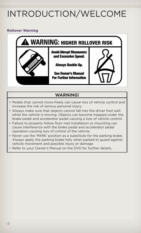
Rollover Warning
WARNING!• Pedals that cannot move freely can cause loss of vehicle control and
increase the risk of serious personal injury.• Always make sure that objects cannot fall into the driver foot well
while the vehicle is moving. Objects can become trapped under thebrake pedal and accelerator pedal causing a loss of vehicle control.
• Failure to properly follow floor mat installation or mounting cancause interference with the brake pedal and accelerator pedaloperation causing loss of control of the vehicle.
• Never use the ‘PARK’ position as a substitute for the parking brake.Always apply the parking brake fully when parked to guard againstvehicle movement and possible injury or damage.
• Refer to your Owner's Manual on the DVD for further details.
INTRODUCTION/WELCOME
4

USE OF AFTERMARKET PRODUCTS (ELECTRONICS)The use of aftermarket devices including cell phones, MP3 players, GPSsystems, or chargers may affect the performance of on-board wirelessfeatures including Keyless Enter-N-Go™ and Remote Start range. If you areexperiencing difficulties with any of your wireless features, try disconnectingyour aftermarket devices to see if the situation improves. If your symptomspersist, please see an authorized dealer.
CHRYSLER, DODGE, JEEP, RAM TRUCK, ATF+4, MOPAR and Uconnect areregistered trademarks of Chrysler Group LLC.COPYRIGHT ©2012 CHRYSLER GROUP LLC
INTRODUCTION/WELCOME
5
DR
IVER
CO
CK
PIT
CONTROLS AT A GLANCE
6
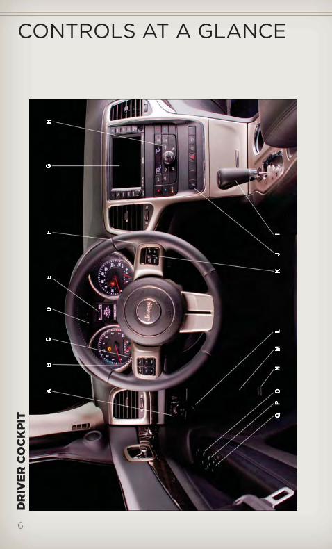
A.
Hea
dlig
htS
wit
chp
g.2
8
B.
Ele
ctro
nic
Veh
icle
Info
rmat
ion
Cen
ter
(EV
IC)
Co
ntro
lsp
g.7
8
C.
Turn
Sig
nal/
Wip
er/W
ashe
r/H
igh
Bea
ms
Leve
r(b
ehin
dst
eeri
ngw
heel
)p
g.2
9
D.
Inst
rum
ent
Clu
ster
pg
.8
E.
Ele
ctro
nic
Veh
icle
Info
rmat
ion
Cen
ter
(EV
IC)
Dis
pla
yp
g.7
8
F.Ig
niti
on
Sw
itch
(beh
ind
stee
ring
whe
el)
G.
Aud
ioS
yste
m(t
ouc
h-sc
reen
-rad
iosh
ow
n)p
g.4
2
H.
Clim
ate
Co
ntro
lsp
g.3
5
I.Tr
ansm
issi
on
Gea
rS
elec
tor
J.SW
ITC
HPA
NE
L
−E
lect
roni
cS
tab
ility
Co
ntro
lp
g.9
9
−To
w/H
aulp
g.9
0
−H
eate
dS
teer
ing
Whe
elp
g.2
5
−H
azar
dS
wit
ch
−P
ow
erIn
vert
erp
g.8
2
−P
arkS
ense
®p
g.3
6
K.
Sp
eed
Co
ntro
lpg
.30
L.F
uelD
oo
rR
elea
sep
g.1
14
M.
Ho
od
Rel
ease
pg
.114
N.
Par
king
Bra
keR
elea
se
O.
Po
wer
Mir
rors
P.P
ow
erW
ind
ow
s
Q.
Po
wer
Do
or
Lock
s
CONTROLS AT A GLANCE
7
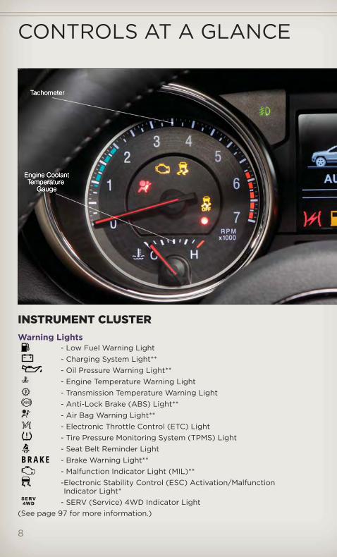
INSTRUMENT CLUSTERWarning Lights
- Low Fuel Warning Light- Charging System Light**- Oil Pressure Warning Light**- Engine Temperature Warning Light- Transmission Temperature Warning Light- Anti-Lock Brake (ABS) Light**- Air Bag Warning Light**- Electronic Throttle Control (ETC) Light- Tire Pressure Monitoring System (TPMS) Light- Seat Belt Reminder Light
BRAKE - Brake Warning Light**- Malfunction Indicator Light (MIL)**-Electronic Stability Control (ESC) Activation/MalfunctionIndicator Light*
- SERV (Service) 4WD Indicator Light(See page 97 for more information.)
CONTROLS AT A GLANCE
8
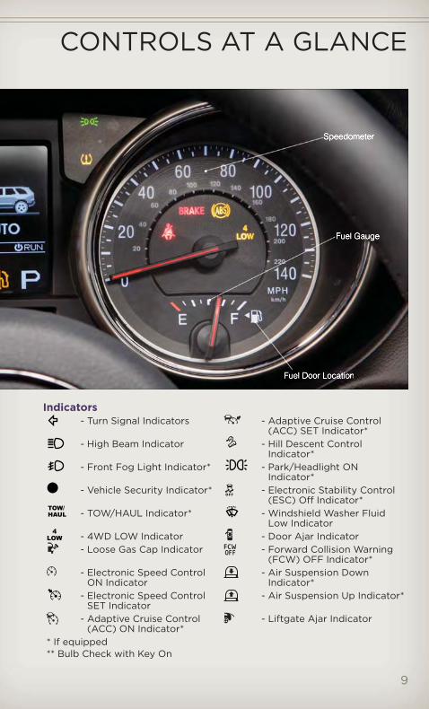
Indicators- Turn Signal Indicators - Adaptive Cruise Control
(ACC) SET Indicator*- High Beam Indicator - Hill Descent Control
Indicator*- Front Fog Light Indicator* - Park/Headlight ON
Indicator*- Vehicle Security Indicator* - Electronic Stability Control
(ESC) Off Indicator*- TOW/HAUL Indicator* - Windshield Washer Fluid
Low Indicator- 4WD LOW Indicator - Door Ajar Indicator- Loose Gas Cap Indicator - Forward Collision Warning
(FCW) OFF Indicator*- Electronic Speed Control
ON Indicator- Air Suspension Down
Indicator*- Electronic Speed Control
SET Indicator- Air Suspension Up Indicator*
- Adaptive Cruise Control(ACC) ON Indicator*
- Liftgate Ajar Indicator
* If equipped** Bulb Check with Key On
CONTROLS AT A GLANCE
9
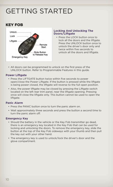
KEY FOBLocking And Unlocking TheDoors/Liftgate
• Press the LOCK button once tolock all the doors and the liftgate.Press the UNLOCK button once tounlock the driver’s door only andtwice within five seconds tounlock all the doors and liftgate.
• All doors can be programmed to unlock on the first press of theUNLOCK button. Refer to Programmable Features in this guide.
Power Liftgate• Press the LIFTGATE button twice within five seconds to power
open/close the Power Liftgate. If the button is pressed while the liftgateis being power closed, the liftgate will reverse to the full open position.
• Also, the power liftgate may be closed by pressing the Liftgate switchlocated on the left rear trim panel, near the liftgate opening. Pressingonce will close the liftgate only. This button cannot be used to open theliftgate.
Panic Alarm• Press the PANIC button once to turn the panic alarm on.
• Wait approximately three seconds and press the button a second time toturn the panic alarm off.
Emergency Key• Should the battery in the vehicle or the Key Fob transmitter go dead,
there is an emergency key located in the Key Fob that can be used forlocking and unlocking the doors. To remove the emergency key, slide thebutton at the top of the Key Fob sideways with your thumb and then pullthe key out with your other hand.
• The emergency key is used to unlock/lock the driver's door and theglove compartment.
GETTING STARTED
10

• In case the Key Fob battery isdead, use the emergency key toopen the door. If the vehicle isequipped with KeylessEnter-N-Go™, remove the ENGINESTART/STOP button by insertingthe metal part of the emergencykey under the chrome bezel at the6 o’clock position and gently prythe button loose.
NOTE: The ENGINE START/STOP button should only be removed orinserted with the ignition in the LOCK position (OFF position for KeylessEnter-N-Go™).
• With the ENGINE START/STOPbutton removed, start the vehicleby inserting the Key Fob in theignition and turning to the Startposition.
CAUTION!• If your vehicle battery becomes low or dead, your Key Fob will
become locked in the ignition.• Do not attempt to remove the Key Fob while in this condition,
damage could occur to the Key Fob or ignition module. Onlyremove the emergency key for locking and unlocking the doors.
• Leave the Key Fob in the ignition and either:• Jump Start the vehicle.• Charge the battery.• Contact your dealer for assistance on how to remove the Key
Fob using the manual over ride method.
GETTING STARTED
11

WARNING!• Leaving unattended children in a vehicle is dangerous for a number
of reasons. A child or others could be severely injured or killed.Children should be warned not to touch the parking brake, brakepedal, or the shift lever. Do not leave the Key Fob inside the vehicleor in the ignition. A child could start the vehicle, operate powerwindows, other controls, or move the vehicle.
• Do not leave children or animals inside parked vehicles in hotweather. Interior heat build-up may cause them to be severelyinjured or killed.
• Keep Key Fob transmitters away from children. Operation of theRemote Start System, windows, door locks or other controls couldcause serious injury or death.
• Driving with the liftgate open can allow poisonous exhaust gasesinto your vehicle. You and your passengers could be injured bythese fumes. Keep the flipper glass closed when you are operatingthe vehicle.
REMOTE START• Press the REMOTE START button x2 on the Key Fob twice within five
seconds. Pressing the REMOTE START button a third time shuts theengine off.
• To drive the vehicle, with a valid Keyless Enter-N-Go™ Key Fob within 5 ft(1.5m) of the driver's side of the vehicle, grab the front driver doorhandle to unlock the driver's door automatically, then press theStart/Stop switch. Or press the UNLOCK button, insert the Key Fob inthe ignition and turn to the ON/RUN position.
• With remote start, the engine will only run for 15 minutes (timeout)unless the ignition is placed in the ON/RUN position.
• The vehicle must be started with the Key Fob after two consecutivetimeouts.
WARNING!• Do not start or run an engine in a closed garage or confined area.
Exhaust gas contains Carbon Monoxide (CO) which is odorless andcolorless. Carbon Monoxide is poisonous and can cause you orothers to be severely injured or killed when inhaled.
• Keep Key Fob transmitters away from children. Operation of theRemote Start System, windows, door locks or other controls couldcause you and others to be severely injured or killed.
GETTING STARTED
12
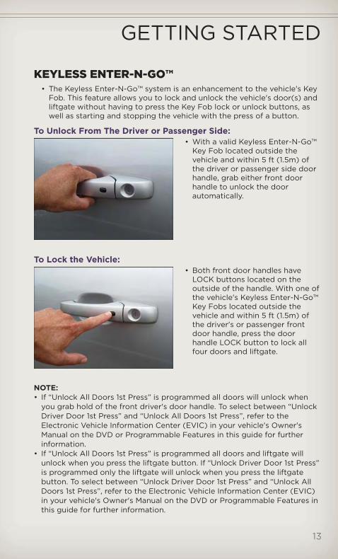
KEYLESS ENTER-N-GO™• The Keyless Enter-N-Go™ system is an enhancement to the vehicle's Key
Fob. This feature allows you to lock and unlock the vehicle's door(s) andliftgate without having to press the Key Fob lock or unlock buttons, aswell as starting and stopping the vehicle with the press of a button.
To Unlock From The Driver or Passenger Side:• With a valid Keyless Enter-N-Go™
Key Fob located outside thevehicle and within 5 ft (1.5m) ofthe driver or passenger side doorhandle, grab either front doorhandle to unlock the doorautomatically.
To Lock the Vehicle:• Both front door handles have
LOCK buttons located on theoutside of the handle. With one ofthe vehicle's Keyless Enter-N-Go™Key Fobs located outside thevehicle and within 5 ft (1.5m) ofthe driver's or passenger frontdoor handle, press the doorhandle LOCK button to lock allfour doors and liftgate.
NOTE:• If “Unlock All Doors 1st Press” is programmed all doors will unlock when
you grab hold of the front driver's door handle. To select between “UnlockDriver Door 1st Press” and “Unlock All Doors 1st Press”, refer to theElectronic Vehicle Information Center (EVIC) in your vehicle's Owner'sManual on the DVD or Programmable Features in this guide for furtherinformation.
• If “Unlock All Doors 1st Press” is programmed all doors and liftgate willunlock when you press the liftgate button. If “Unlock Driver Door 1st Press”is programmed only the liftgate will unlock when you press the liftgatebutton. To select between “Unlock Driver Door 1st Press” and “Unlock AllDoors 1st Press”, refer to the Electronic Vehicle Information Center (EVIC)in your vehicle's Owner's Manual on the DVD or Programmable Features inthis guide for further information.
GETTING STARTED
13

• If a Key Fob is detected in the vehicle when locking the vehicle using thepower door lock switch, the doors and liftgate will unlock and the horn willchirp three times. On the third attempt, your Key Fob can be locked insidethe vehicle.
• After pressing the Keyless Enter-N-Go™ LOCK button, you must wait2 seconds before you can lock or unlock the vehicle using the door handle.This is done to allow you to check if the vehicle is locked by pulling on thedoor handle without the vehicle reacting and unlocking.
• If a Keyless Enter-N-Go™ door handle has not been used for 72 hours, theKeyless Enter-N-Go™ feature for that handle may time out. Pulling thedeactivated front door handle will reactivate the door handle's KeylessEnter-N-Go™ feature.
Installing And Removing The ENGINE START/STOP ButtonInstalling The Button• Remove the Key Fob from the ignition switch.
• Insert the ENGINE START/STOP button into the ignition switch with thelettering facing up and readable.
• Press firmly on the center of the button to secure it into position.
Removing The Button• The ENGINE START/STOP button can be removed from the ignition
switch for Key Fob use.
• Insert the metal part of the emergency key under the chrome bezel atthe 6 o’clock position and gently pry the button loose.
NOTE:• The ENGINE START/STOP button
should only be removed or insertedwith the ignition in the LOCKposition (OFF position for KeylessEnter-N-Go™).
GETTING STARTED
14
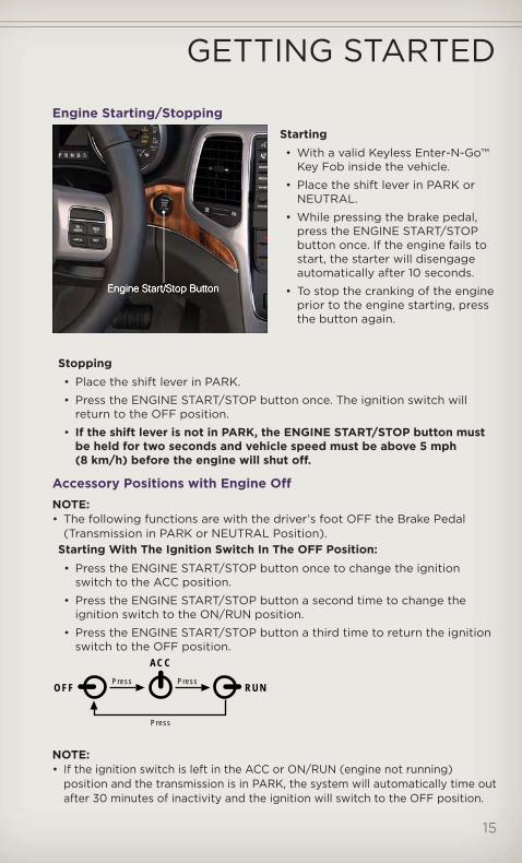
Engine Starting/StoppingStarting• With a valid Keyless Enter-N-Go™
Key Fob inside the vehicle.
• Place the shift lever in PARK orNEUTRAL.
• While pressing the brake pedal,press the ENGINE START/STOPbutton once. If the engine fails tostart, the starter will disengageautomatically after 10 seconds.
• To stop the cranking of the engineprior to the engine starting, pressthe button again.
Stopping• Place the shift lever in PARK.
• Press the ENGINE START/STOP button once. The ignition switch willreturn to the OFF position.
• If the shift lever is not in PARK, the ENGINE START/STOP button mustbe held for two seconds and vehicle speed must be above 5 mph(8 km/h) before the engine will shut off.
Accessory Positions with Engine OffNOTE:• The following functions are with the driver’s foot OFF the Brake Pedal
(Transmission in PARK or NEUTRAL Position).Starting With The Ignition Switch In The OFF Position:• Press the ENGINE START/STOP button once to change the ignition
switch to the ACC position.
• Press the ENGINE START/STOP button a second time to change theignition switch to the ON/RUN position.
• Press the ENGINE START/STOP button a third time to return the ignitionswitch to the OFF position.
NOTE:• If the ignition switch is left in the ACC or ON/RUN (engine not running)
position and the transmission is in PARK, the system will automatically time outafter 30 minutes of inactivity and the ignition will switch to the OFF position.
OFF RUN
ACC
Press Press
Press
GETTING STARTED
15

THEFT ALARMTo Arm
• Keyless Enter-N-Go™ button installed: Press the Keyless Enter-N-Go™Start/Stop button until the Electronic Vehicle Information Center (EVIC)indicates that the vehicle ignition is “OFF”. Press the power door lockswitch while the door is open, press the Key Fob LOCK button, or withone of the Key Fobs located outside the vehicle and within 5 ft (1.5m) ofthe driver's and passenger front door handles, press the KeylessEnter-N-Go™ LOCK button located on the door handle.
• Keyless Enter-N-Go™ button not installed: Turn the ignition switch to the“OFF” position. Press the power door lock switch while the door is open,press the Key Fob LOCK button, or with one of the Key Fobs locatedoutside the vehicle and within 5 ft (1.5m) of the driver's and passengerfront door handles, press the Keyless Enter-N-Go™ LOCK button locatedon the door handle.
NOTE: After pressing the Keyless Enter-N-Go™ LOCK button, you must waittwo seconds before you can lock or unlock the vehicle via the door handle.
To Disarm• Keyless Enter-N-Go™ button installed: Press the Key Fob UNLOCK
button or with one of the Key Fobs located outside the vehicle andwithin 5 ft (1.5m) of the driver's and passenger front door handles, grabthe Keyless Enter-N-Go™ door handle and enter the vehicle, then pressthe Keyless Enter-N-Go™ Start/Stop button (requires at least one validKey Fob in the vehicle).
• Keyless Enter-N-Go™ button not installed: Press the Key Fob UNLOCKbutton or with one of the Key Fobs located outside the vehicle andwithin 5 ft (1.5m) of the driver's and passenger front door handles, grabthe Keyless Enter-N-Go™ door handle and enter the vehicle, then turn theignition to the ON/RUN position.
SEAT BELT• Be sure everyone in your vehicle is in a seat and using a seat belt
properly.
• Position the lap belt across your thighs, below your abdomen. To removeslack in the lap portion, pull up a bit on the shoulder belt. To loosen thelap belt if it is too tight, tilt the latch plate and pull on the lap belt. Asnug belt reduces the risk of sliding under the belt in a collision.
• Position the shoulder belt on your chest so that it is comfortable and notresting on your neck. The retractor will withdraw any slack in the belt.
• A shoulder belt placed behind you will not protect you from injury duringa collision. You are more likely to hit your head in a collision if you do notwear your shoulder belt. The lap and shoulder belt are meant to be usedtogether.
GETTING STARTED
16

• A belt that is too loose will not protect you properly. In a sudden stopyou could move too far forward, increasing the possibility of injury. Wearyour seat belt snugly.
• A frayed or torn belt could rip apart in a collision and leave you with noprotection. Inspect the belt system periodically, checking for cuts, frays,or loose parts. Damaged parts must be replaced immediately. Do notdisassemble or modify the system. Seat belt assemblies must bereplaced after a collision if they have been damaged (bent retractor, tornwebbing, etc.).
• The seat belts for both front seating positions are equipped withpretensioning devices that are designed to remove slack from the seatbelt in the event of a collision.
• A deployed pretensioner or a deployed air bag must be replacedimmediately.
WARNING!In a collision, you and your passengers can suffer much greaterinjuries if you are not buckled up properly. You can strike the interiorof your vehicle or other passengers, or you can be thrown out of thevehicle. Always be sure you and others in your vehicle are buckled upproperly.
SUPPLEMENTAL RESTRAINT SYSTEM (SRS) — AIRBAGS
• This vehicle has Advanced Front Air Bags for both the driver and rightfront passenger as a supplement to the seat belt restraint system. TheAdvanced Front Air Bags will not deploy in every type of collision.
• Advanced Front Air Bags are designed to provide additional protectionby supplementing the seat belts in certain frontal collisions dependingon the severity and type of collision. Advanced Front Air Bags are notexpected to reduce the risk of injury in rear, side, or rollover collisions.
• This vehicle is equipped with Supplemental Side Air Bag InflatableCurtains to protect the driver, front and rear passengers sitting next to awindow.
• This vehicle is equipped with Supplemental Seat-Mounted Side Air Bagsto provide enhanced protection to help protect an occupant during aside impact.
• If the Air Bag Warning Light is not on during starting, stays on, orturns on while driving, have the vehicle serviced by an authorized servicecenter immediately.
• Refer to the Owner's Manual on the DVD for further details regarding theSupplemental Restraint System (SRS).
GETTING STARTED
17

WARNING!• Relying on the air bags alone could lead to more severe injuries in a
collision. The air bags work with your seat belt to restrain youproperly. In some collisions, the air bags won't deploy at all. Alwayswear your seat belts even though you have air bags.
• Being too close to the steering wheel or instrument panel duringAdvanced Front Air Bag deployment could cause serious injury,including death. Air bags need room to inflate. Sit back, comfortablyextending your arms to reach the steering wheel or instrumentpanel.
• Supplemental Side Air Bag Inflatable Curtains and SupplementalSeat-Mounted Side Air Bags need room to inflate. Do not leanagainst the door or window. Sit upright in the center of the seat.
• Being too close to the Supplemental Side Air Bag Inflatable Curtainand/or Seat-Mounted Side Air Bag during deployment could causeyou to be severely injured or killed.
• Do not drive your vehicle after the air bags have deployed. If youare involved in another collision, the air bags will not be in place toprotect you.
• After any collision, the vehicle should be taken to an authorizeddealer immediately.
CHILD RESTRAINTS• Children 12 years and under should ride properly buckled up in a rear
seat, if available. According to crash statistics, children are safer whenproperly restrained in the rear seats rather than in the front.
• Every state in the United States and all Canadian provinces require thatsmall children ride in proper restraint systems. This is the law, and youcan be prosecuted for ignoring it.
Installing The LATCH - Compatible Child Restraint System• Your vehicle's second row passenger seats are equipped with the child
restraint anchorage system called LATCH, which stands for LowerAnchors and Tether for CHildren.
• All three rear seating positions have lower anchorages that are capableof accommodating LATCH-compatible child seats having flexible,webbing-mounted lower attachments.
• Child seats with fixed lower attachments must be installed in theoutboard positions only.
• The vehicle's seat belt must be used for the center position.
• Never install LATCH-compatible child seats such that two seats share acommon lower anchorage.
GETTING STARTED
18
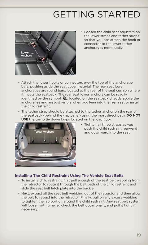
• Loosen the child seat adjusters onthe lower straps and tether strapsso that you can attach the hook orconnector to the lower tetheranchorages more easily.
• Attach the lower hooks or connectors over the top of the anchoragebars, pushing aside the seat cover material. The rear seat loweranchorages are round bars, located at the rear of the seat cushion whereit meets the seatback. The rear seat lower anchors can be readilyidentified by the symbol located on the seatback directly above theanchorages and are just visible when you lean into the rear seat to installthe child restraint.
• The tether strap should be attached to the tether anchor on the rear ofthe seatback (behind the gap panel) using the most direct path. DO NOTUSE the cargo tie down loops located on the load floor.
• Tighten all three straps as youpush the child restraint rearwardand downward into the seat.
Installing The Child Restraint Using The Vehicle Seat Belts• To install a child restraint, first pull enough of the seat belt webbing from
the retractor to route it through the belt path of the child restraint andslide the seat belt latch plate into the buckle.
• Next, extract all the seat belt webbing out of the retractor and then allowthe belt to retract into the retractor. Finally, pull on any excess webbingto tighten the lap portion around the child restraint. Any seat belt systemwill loosen with time, so check the belt occasionally, and pull it tight ifnecessary.
GETTING STARTED
19
• Once you have completed securing the child restraint with the seat belt,secure the top tether strap. The tether strap should be attached to thetether anchor on the rear of the seatback (behind the gap panel) usingthe most direct path. DO NOT USE the cargo tie down loops located onthe load floor.
WARNING!• In a collision, an unrestrained child, even a tiny baby, can become a
projectile inside the vehicle. The force required to hold even aninfant on your lap could become so great that you could not holdthe child, no matter how strong you are. The child and others couldbe severely injured or killed. Any child riding in your vehicle shouldbe in a proper restraint for the child's size.
• Improper installation of a child restraint to the LATCH anchoragescan lead to failure of an infant or child restraint. The child could beseverely injured or killed. Follow the manufacturer’s directionsexactly when installing an infant or child restraint.
• An incorrectly anchored tether strap could lead to increased headmotion and possible injury to the child. Use only the anchorpositions directly behind the child seat to secure a child restrainttop tether strap.
• Rearward-facing child seats must never be used in the front seat ofa vehicle with a front passenger air bag. An air bag deploymentcould cause infants in this position to be severely injured or killed.
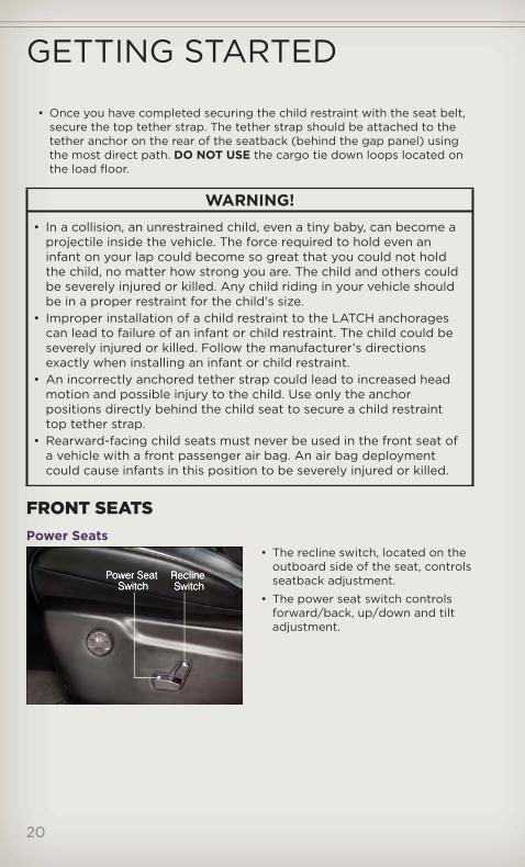
FRONT SEATSPower Seats
• The recline switch, located on theoutboard side of the seat, controlsseatback adjustment.
• The power seat switch controlsforward/back, up/down and tiltadjustment.
GETTING STARTED
20

Power Lumbar• Push the switch forward to
increase the lumbar support. Pushthe switch rearward to decreasethe lumbar support.
• Pushing upward or downward onthe switch will raise and lower theposition of the support.
Memory Seat• The memory seat feature allows
you to save two different driverseating positions (excludinglumbar position), driver's outsidemirror, tilt/telescoping steeringcolumn position, and radio stationpreset settings. The memory seatbuttons are located on the driver'sdoor panel.
• Adjust all memory profile settings,press the SET button then press 1or 2 within five seconds.
• To program a Key Fob to the memory position, place the ignition switchin the LOCK position and remove the Key Fob, press and release theLOCK button on the Key Fob to be programmed within 5 seconds ofpressing button 1 or 2.
• Place the ignition switch in the ON/RUN position, select Remote Linkedto Memory in the Electronic Vehicle Information Center (EVIC) and enterYes.
• Press 1 or 2 to recall the saved positions, or press UNLOCK on theprogrammed Key Fob.
• Refer to the Owner's Manual on the DVD for further details.
GETTING STARTED
21
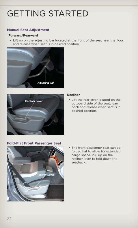
Manual Seat AdjustmentForward/Rearward• Lift up on the adjusting bar located at the front of the seat near the floor
and release when seat is in desired position.
Recliner• Lift the rear lever located on the
outboard side of the seat, leanback and release when seat is indesired position.
Fold-Flat Front Passenger Seat• The front passenger seat can be
folded flat to allow for extendedcargo space. Pull up on therecliner lever to fold down theseatback.
GETTING STARTED
22

CAUTION!Do not place any article under a power seat or impede its ability tomove as it may cause damage to the seat controls. Seat travel maybecome limited if movement is stopped by an obstruction in the seat'spath.
WARNING!• Adjusting a seat while the vehicle is moving is dangerous. The
sudden movement of the seat could cause you to lose control. Theseat belt might not be properly adjusted, and you could be severelyinjured or killed. Only adjust a seat while the vehicle is parked.
• Do not ride with the seatback reclined so that the seat belt is nolonger resting against your chest. In a collision, you could slideunder the seat belt and be severely injured or killed. Use the reclineronly when the vehicle is parked.
REAR SEATS60/40 Split Rear Seat
To Lower Rear Seatback• With the front seats fully upright
and positioned forward, pullupward on the release lever andfold the rear seatback down.
To Raise Rear Seatback• Raise the rear seatback and lock it
into place.
To Recline Rear Seatback• To recline the seatback, lean forward before lifting the handle, then lean
back to the desired position and release the handle. Lift the handle toreturn the seatback to an upright position.
GETTING STARTED
23

HEATED/VENTILATED SEATSFront Heated Seats
• The controls for front heated seatsare located near the bottomcenter of the instrument panel(below the Climate Controls).
• Press the switch once to selectHigh-level heating. Press theswitch a second time to selectLow-level heating. Press theswitch a third time to shut theheating elements Off.
• If the High-level setting is selected, the system will automatically switchto Low-level after approximately 55 minutes. The Low-level setting willturn Off automatically after approximately 45 minutes.
Front Ventilated Seats• Located in the seat cushion and seatback are small fans that draw the air
from the passenger compartment and blow air through fine perforationsin the seat cover to help keep the driver and front passenger cooler inhigher ambient temperatures.
• There are two ventilated seat switches that allow the driver andpassenger to operate the seats independently. The ventilated seatswitches are located on the switch bank in the center stack of theinstrument panel, just below the climate controls. The ventilated seatswitches are used to control the speed of the fans located in the seat.Press the switch once to choose HIGH, press it a second time to chooseLOW. Pressing the switch a third time will turn the ventilated seat OFF.When HIGH speed is selected both lights on the switch will beilluminated. When LOW speed is selected one light will be illuminated.
Rear Heated Seats• Second row heated seat switches
are located on the rear of thecenter console.
• Press the switch once to selectHigh-level heating. Press theswitch a second time to selectLow-level heating. Press theswitch a third time to shut theheating elements Off.
GETTING STARTED
24

• If the High-level setting is selected, the system will automatically switchto Low-level after approximately 55 minutes. The Low-level setting willturn Off automatically after approximately 45 minutes.
WARNING!• Persons who are unable to feel pain to the skin because of
advanced age, chronic illness, diabetes, spinal cord injury,medication, alcohol use, exhaustion or other physical conditionsmust exercise care when using the seat heater. It may cause burnseven at low temperatures, especially if used for long periods of time.
• Do not place anything on the seat that insulates against heat, suchas a blanket or cushion. This may cause the seat heater to overheat.Sitting in a seat that has been overheated could cause serious burnsdue to the increased surface temperature of the seat.
HEATED STEERING WHEEL• The steering wheel contains a
heating element that heats thesteering wheel to one temperaturesetting.
• The heated steering wheel switchis located on the centerinstrument panel below theclimate controls.
• Press the switch once to turn the heating element On. Press the switch asecond time to turn the heating element Off.
• Once the heated steering wheel has been turned on, it will operate forapproximately 58 to 70 minutes before automatically shutting off. Theheated steering wheel can shut off early or may not turn on when thesteering wheel is already warm.
GETTING STARTED
25

TILT/TELESCOPING STEERING COLUMNManual - Tilt/Telescoping Steering Column
• The tilt/telescoping control handleis located below the steeringwheel at the end of the steeringcolumn.
• Push the handle down to unlockthe steering column.
• To tilt the steering column, movethe steering wheel upward ordownward as desired. To lengthenor shorten the steering column,pull the steering wheel outward orpush it inward as desired.
• Pull up on the handle to lock the column firmly in place.
Power - Tilt/Telescoping Steering Column• The power tilt/telescoping
steering control is located belowthe turn signal/wiper/washer/highbeam lever on the steeringcolumn.
• To tilt the steering column, movethe power tilt/telescoping controlup or down as desired. Tolengthen or shorten the steeringcolumn, pull the control towardyou or push the control away fromyou as desired.
WARNING!• Do not adjust the steering wheel while driving. The tilt/telescoping
adjustment must be locked while driving. Adjusting the steeringwheel while driving or driving without the tilt/telescopingadjustment locked could cause the driver to lose control of thevehicle. Failure to follow this warning may result in you and othersbeing severely injured or killed.
• Moving the steering column while the vehicle is moving isdangerous. Without a stable steering column, you could lose controlof the vehicle and have a collision. Adjust the column only while thevehicle is stopped.
GETTING STARTED
26
ENGINE BREAK-IN RECOMMENDATIONS• A long break-in period is not required for the engine and drivetrain
(transmission and axle) in your vehicle.
• Drive moderately during the first 300 miles (500 km). After the initial60 miles (100 km), speeds up to 50 or 55 mph (80 or 90 km/h) aredesirable.
• While cruising, brief full-throttle acceleration within the limits of localtraffic laws contributes to a good break-in. Wide-open throttleacceleration in low gear can be detrimental and should be avoided.
• The engine oil installed in the engine at the factory is a high-qualityenergy conserving type lubricant. Oil changes should be consistent withanticipated climate conditions under which vehicle operations will occur.For the recommended viscosity and quality grades, refer to “MaintainingYour Vehicle”.
NOTE: A new engine may consume some oil during its first few thousandmiles (kilometers) of operation. This should be considered a normal part ofthe break-in and not interpreted as an indication of difficulty.
CAUTION!Never use Non-Detergent Oil or Straight Mineral Oil in the engine ordamage may result.
ENGINE BREAK-IN RECOMMENDATIONS — SRT8 VERSIONS• A long break-in period is not required for the drivetrain (engine,
transmission, and rear axle) in your new vehicle.
• Drive moderately during the first 500 mi (800 km). After the initial 60 mi(100 km), speeds up to 50 or 55 mph (80 or 90 km/h) are desirable.
• While cruising, brief full-throttle acceleration within the limits of localtraffic laws contributes to a good break-in. However, wide-open throttleacceleration in low gear can be detrimental and should be avoided.
• The engine oil, transmission fluid, and axle lubricant installed at thefactory is high-quality and energy-conserving. Oil, fluid, and lubricantchanges should be consistent with anticipated climate and conditionsunder which vehicle operations will occur. For the recommendedviscosity and quality grades, refer to “Maintaining Your Vehicle”.
NOTE: A new engine may consume some oil during its first few thousandmiles (kilometers) of operation. This should be considered a normal part ofthe break-in and not interpreted as an indication of difficulty.
CAUTION!Never use Non-Detergent Oil or Straight Mineral Oil in the engine ordamage may result.
OPERATING YOUR VEHICLE
27

HEADLIGHT SWITCHAutomatic Headlights/ParkingLights/Headlights
• Rotate the headlight switch,located on the instrument panel tothe left of the steering wheel, tothe first detent for parking lights
and to the second detentfor headlights .
• With the parking lights or lowbeam headlights on, push theheadlight switch once for foglights.
• Rotate the headlight switch to “A”for AUTO headlights.
• When set to “A” (AUTO), the system automatically turns the headlightson or off based on ambient light levels.
SmartBeams™• This system automatically controls the use of the headlight high beams.
Refer to Programmable Features in Electronics for further details.
Instrument Panel Dimmer• Rotate the dimmer control to the extreme bottom position to fully dim
the instrument panel lights and prevent the interior lights fromilluminating when a door is opened.
• Rotate the dimmer control up to increase the brightness of theinstrument panel when the parking lights or headlights are on.
• Rotate the dimmer control up to the next detent position to fullybrighten the odometer and radio when the parking lights or headlightsare on. Refer to your Media Center/Radio User Manual on the DVD fordisplay dimming.
• Rotate the dimmer control up to the last detent position to turn on theinterior lighting.
OPERATING YOUR VEHICLE
28
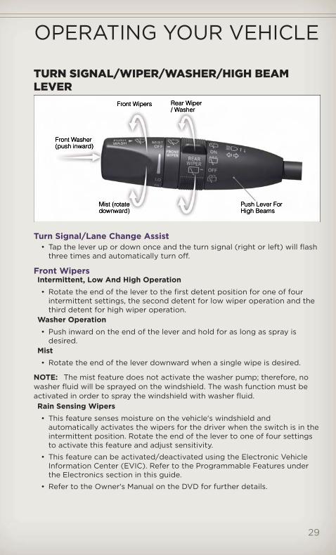
TURN SIGNAL/WIPER/WASHER/HIGH BEAMLEVER
Turn Signal/Lane Change Assist• Tap the lever up or down once and the turn signal (right or left) will flash
three times and automatically turn off.
Front WipersIntermittent, Low And High Operation• Rotate the end of the lever to the first detent position for one of four
intermittent settings, the second detent for low wiper operation and thethird detent for high wiper operation.
Washer Operation• Push inward on the end of the lever and hold for as long as spray is
desired.Mist• Rotate the end of the lever downward when a single wipe is desired.
NOTE: The mist feature does not activate the washer pump; therefore, nowasher fluid will be sprayed on the windshield. The wash function must beactivated in order to spray the windshield with washer fluid.Rain Sensing Wipers• This feature senses moisture on the vehicle's windshield and
automatically activates the wipers for the driver when the switch is in theintermittent position. Rotate the end of the lever to one of four settingsto activate this feature and adjust sensitivity.
• This feature can be activated/deactivated using the Electronic VehicleInformation Center (EVIC). Refer to the Programmable Features underthe Electronics section in this guide.
• Refer to the Owner's Manual on the DVD for further details.
OPERATING YOUR VEHICLE
29
Rear WiperWiper Operation• Rotate the center portion of the lever forward to the first detent for
intermittent operation and to the second detent for rear wiper operation.Washer Operation• Rotate the center portion of the lever past the second detent to activate
the rear washer.
High Beam Operation• Push the lever forward to activate the high beams. Pull the lever toward
you for flash to pass.
NOTE: For safe driving, turn off high beams when oncoming traffic ispresent to prevent headlight glare and as a courtesy to other motorists.
AUTO DIMMING MIRRORS• The rearview and driver side exterior mirror automatically adjusts for
headlight glare from vehicles behind you.
• You can turn the feature on or off by pressing the button at the base ofthe rearview mirror. A light next to the button will illuminate to indicatewhen the dimming feature is activated.
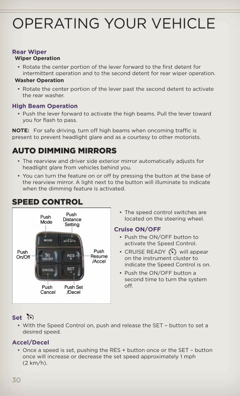
SPEED CONTROL• The speed control switches are
located on the steering wheel.
Cruise ON/OFF• Push the ON/OFF button to
activate the Speed Control.
• CRUISE READY will appearon the instrument cluster toindicate the Speed Control is on.
• Push the ON/OFF button asecond time to turn the systemoff.
Set• With the Speed Control on, push and release the SET – button to set a
desired speed.
Accel/Decel• Once a speed is set, pushing the RES + button once or the SET – button
once will increase or decrease the set speed approximately 1 mph(2 km/h).
OPERATING YOUR VEHICLE
30

• Push and hold the RES + button to accelerate in 5mph (8 km/h)increments or push and hold the SET – button to decelerate in 5mph(8 km/h) increments; release the button to save the new set speed.
Resume• To resume a previously selected set speed in memory, push the RES +
button and release.
Cancel• Push the CANCEL button, or apply the brakes to cancel the set speed
and maintain the set speed memory.
• Push the ON/OFF button to turn the system off and erase the set speedmemory.
Adaptive Cruise Control (ACC)• If your vehicle is equipped with adaptive cruise control the controls
operate exactly the same as the standard cruise control with onedifference. You can set a specified distance you would like to maintainbetween you and the vehicle in front of you.
• If the ACC sensor detects a vehicle ahead, ACC will apply limited brakingor acceleration automatically to maintain a preset following distance,while matching the speed of the vehicle ahead.
• If the sensor does not detect a vehicle directly ahead of you, it functionslike a standard cruise control system, maintaining the speed you set.
Distance Setting (ACC Only)• To set or change the distance setting, press the Distance button and
release. Each time the button is pressed, the distance setting adjustsbetween long (3), medium (2), and short (1). The distance setting willdefault to the last set mode the next time the vehicle is restarted and theACC system is turned on.
• The specified following distance for ACC can be set by varying thedistance setting between 3 (long), 2 (medium), and 1 (short). Using thisdistance setting and the vehicle speed, ACC calculates and sets thedistance to the vehicle ahead. This distance setting displays in the EVIC.
Mode (ACC Only)• If desired, the Adaptive Cruise Control mode can be turned off and the
system can be operated as a standard (fixed speed) Cruise Control.When in the standard (fixed speed) Cruise Control mode the distancesetting feature will be disabled and the system will maintain the speedyou set.
• To change between the different cruise modes, press the MODE buttonwhen the system is in either the OFF, READY or SET state. Pressing ofthe MODE button in any state will result in changing to the new Mode inthe OFF state.
• Refer to your Owner's Manual on the DVD for further information.
OPERATING YOUR VEHICLE
31

Forward Collision Warning• The Forward Collision Warning (FCW) system provides the driver with
audible and visual warnings (within the EVIC) when it detects a potentialfrontal collision. The warnings are intended to provide the driver withenough time to react and avoid the potential collision.
Changing FCW Status• The FCW feature has three settings and can be changed within the
Electronic Vehicle Information Center (EVIC).
• Far
• Near
• Off
NOTE: The FCW settings can only be changed when the vehicle is in PARK.
Far• The default status of FCW is the “Far” setting.
• The far setting provides warnings for potential collisions more distant infront of the vehicle, allowing the driver to have the most reaction time toavoid a collision.
• This setting is designed to provide early warnings per NHTSA (NationalHighway Traffic Safety Administration) recommendations.
• More cautious drivers that do not mind frequent warnings may preferthis setting.
NOTE: This setting gives you the most reaction time.
Near• Changing the FCW status to the “Near” setting, allows the system to
warn you of a potential frontal collision when you are much closer.
• This setting provides less reaction time than the “Far” setting, whichallows for a more dynamic driving experience.
• More dynamic or aggressive drivers that want to avoid frequent warningsmay prefer this setting.
Off• Changing the FCW status to “Off” prevents the system from warning you
of a potential frontal collision.
NOTE:• If FCW is set to “Off”, “FCW OFF” will be displayed in the EVIC.
Refer to the Owner's Manual on the DVD for further details.
OPERATING YOUR VEHICLE
32
WARNING!• Leaving the Electronic or Adaptive Speed Control system on when
not in use is dangerous. You could accidentally set the system orcause it to go faster than you want. You could lose control and havea collision. Always leave the Electronic or Adaptive Speed Controlsystem off when you are not using it.
• Electronic Speed Control can be dangerous where the systemcannot maintain a constant speed. Your vehicle could go too fast forthe conditions, and you could lose control. A collision could be theresult. Do not use Electronic Speed Control in heavy traffic or onroads that are winding, icy, snow-covered or slippery.
• Adaptive Cruise Control (ACC) is a convenience system. It is not asubstitute for active driving involvement. Pay attention to road,traffic, and weather conditions, vehicle speed, distance to thevehicle ahead; and, brake operation to ensure safe operation of thevehicle under all road conditions. Your attention is always requiredwhile driving to maintain safe control of your vehicle. Failure tofollow these warnings can result in a collision or serious personalinjury.
The ACC system:• Does not react to pedestrians, oncoming vehicles, and stationary
objects (i.e., a stopped vehicle in a traffic jam or a disabled vehicle).• Cannot take street, traffic, and weather conditions into account, and
may be limited upon adverse sight distance conditions.• Does not predict the lane curvature or the movement of preceding
vehicles and will not compensate for such changes.• Does not always fully recognize complex driving conditions, which
can result in wrong or missing distance warnings.• May not detect a vehicle ahead when strong light (for example,
sunrise or sunset) is directly shining on the front of the vehicle.• Can only apply a maximum of 25% of the vehicle’s braking
capability, and will not bring the vehicle to a complete stop.You should switch off the ACC system:• When driving in fog, heavy rain, heavy snow, sleet, heavy traffic, and
complex driving situations (i.e., in highway construction zones).• When entering a turn lane or highway off ramp; when driving on
roads that are winding, icy, snow-covered, slippery, or have steepuphill or downhill slopes; and when towing a trailer.
• When circumstances do not allow safe driving at a constant speed.• Failure to follow these warnings can result in a collision.
(Continued)
OPERATING YOUR VEHICLE
33

WARNING! (Continued)
• Forward Collision Warning (FCW) is not intended to avoid acollision on its own. The driver has the responsibility to avoid acollision by controlling the vehicle via braking and steering. Failureto follow this warning could lead to serious injury or death.
ELECTRONIC RANGE SELECTION (ERS)• Electronic Range Select (ERS)
allows you to limit the highestavailable transmission gear, andcan be activated during anydriving condition. When towing atrailer or operating the vehicle inoff-road conditions, using ERSshift control will help youmaximize both performance andengine braking.
• To switch from DRIVE mode to ERS mode, tap the shift lever to the left(-) once. The instrument cluster will display the current gear and thetransmission will not upshift beyond that gear. Tapping the shift lever tothe left (-) or right (+) will decrease or increase the top available gear. Todisable ERS, simply hold the shift lever to the right (+) until “D” is againdisplayed in the instrument cluster.
• Switching between ERS and DRIVE mode can be done at any vehiclespeed.
• Refer to your Owner's Manual on the DVD for further details.
OPERATING YOUR VEHICLE
34
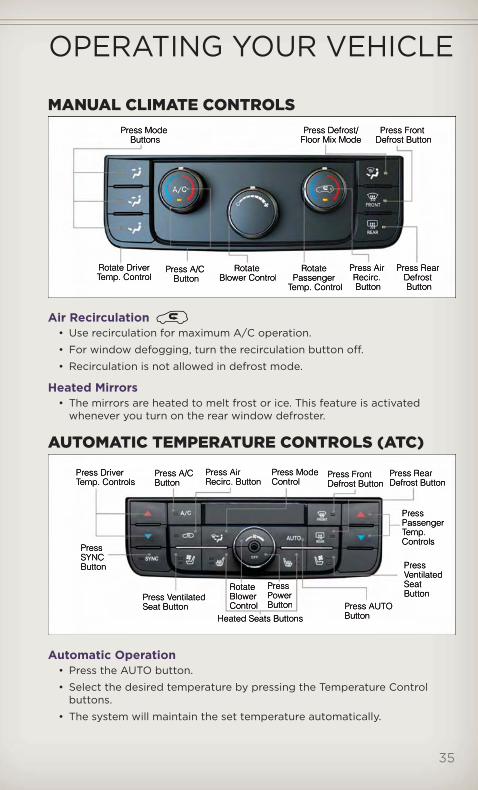
MANUAL CLIMATE CONTROLS
Air Recirculation• Use recirculation for maximum A/C operation.
• For window defogging, turn the recirculation button off.
• Recirculation is not allowed in defrost mode.
Heated Mirrors• The mirrors are heated to melt frost or ice. This feature is activated
whenever you turn on the rear window defroster.
AUTOMATIC TEMPERATURE CONTROLS (ATC)
Automatic Operation• Press the AUTO button.
• Select the desired temperature by pressing the Temperature Controlbuttons.
• The system will maintain the set temperature automatically.
OPERATING YOUR VEHICLE
35
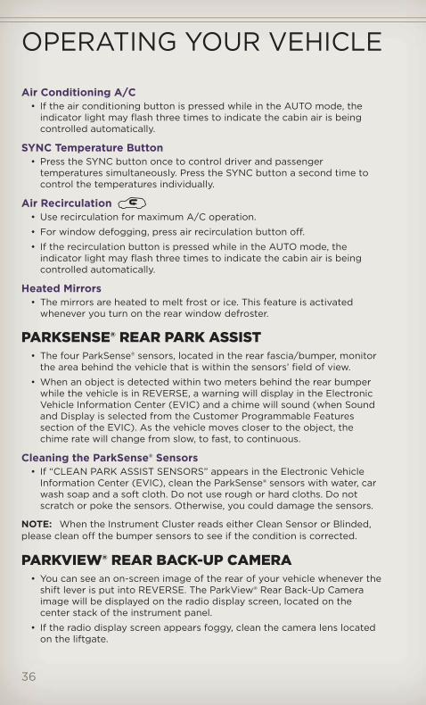
Air Conditioning A/C• If the air conditioning button is pressed while in the AUTO mode, the
indicator light may flash three times to indicate the cabin air is beingcontrolled automatically.
SYNC Temperature Button• Press the SYNC button once to control driver and passenger
temperatures simultaneously. Press the SYNC button a second time tocontrol the temperatures individually.
Air Recirculation• Use recirculation for maximum A/C operation.
• For window defogging, press air recirculation button off.
• If the recirculation button is pressed while in the AUTO mode, theindicator light may flash three times to indicate the cabin air is beingcontrolled automatically.
Heated Mirrors• The mirrors are heated to melt frost or ice. This feature is activated
whenever you turn on the rear window defroster.
PARKSENSE® REAR PARK ASSIST• The four ParkSense® sensors, located in the rear fascia/bumper, monitor
the area behind the vehicle that is within the sensors’ field of view.
• When an object is detected within two meters behind the rear bumperwhile the vehicle is in REVERSE, a warning will display in the ElectronicVehicle Information Center (EVIC) and a chime will sound (when Soundand Display is selected from the Customer Programmable Featuressection of the EVIC). As the vehicle moves closer to the object, thechime rate will change from slow, to fast, to continuous.
Cleaning the ParkSense® Sensors• If “CLEAN PARK ASSIST SENSORS” appears in the Electronic Vehicle
Information Center (EVIC), clean the ParkSense® sensors with water, carwash soap and a soft cloth. Do not use rough or hard cloths. Do notscratch or poke the sensors. Otherwise, you could damage the sensors.
NOTE: When the Instrument Cluster reads either Clean Sensor or Blinded,please clean off the bumper sensors to see if the condition is corrected.
PARKVIEW® REAR BACK-UP CAMERA• You can see an on-screen image of the rear of your vehicle whenever the
shift lever is put into REVERSE. The ParkView® Rear Back-Up Cameraimage will be displayed on the radio display screen, located on thecenter stack of the instrument panel.
• If the radio display screen appears foggy, clean the camera lens locatedon the liftgate.
OPERATING YOUR VEHICLE
36

WARNING!Drivers must be careful when backing up even when using theParkView® Rear Back-Up Camera. Always check carefully behind yourvehicle, and be sure to check for pedestrians, animals, other vehicles,obstructions, or blind spots before backing up. You must continue topay attention while backing up. Failure to do so can result in seriousinjury or death.
BLIND SPOT MONITORING• The Blind Spot Monitoring (BSM) system uses two radar-based sensors,
located inside the rear bumper fascia, to detect Highway licensablevehicles (automobiles, trucks, motorcycles etc.) that enter the blind spotzones from the rear/front/side of the vehicle.
• The Blind Spot Monitoring (BSM) system warning light, located in theoutside mirrors, will illuminate if a vehicle moves into a blind spot zone.
• The BSM system can also be configured to sound an audible (chime)alert and mute the radio to notify you of objects that have entered thedetection zones.
• Refer to your owner's manual on the DVD for further details.
LIFTGATE FLIPPER GLASS• The liftgate flipper glass is
unlocked when the liftgate isunlocked. To open the flipperglass, push up on the windowswitch located on the liftgate.When flipper glass is unlatched itwill not completely raise, lift up onflipper glass handle to open.
NOTE: If a malfunction to the liftgate latch should occur, an emergencyliftgate latch release, located on the inside of the vehicle, can be used toopen the liftgate. The emergency liftgate latch release can be accessedthrough a snap-in cover located on the liftgate trim panel.
OPERATING YOUR VEHICLE
37

WARNING!• Driving with the liftgate or flipper glass open can allow poisonous
exhaust gases into your vehicle. You and your passengers could beinjured by these fumes. Keep the flipper glass closed when you areoperating the vehicle.
• To avoid injury, stand back when opening. Glass may automaticallyrise.
POWER SUNROOF
Manual Open/Close• Press and hold the switch rearward to open or forward to close the
sunroof. Any release of the switch will stop the movement, and thesunroof will remain in a partially open or closed position until the switchis pressed again.
OPERATING YOUR VEHICLE
38
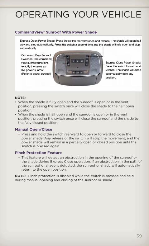
CommandView® Sunroof With Power Shade
NOTE:• When the shade is fully open and the sunroof is open or in the vent
position, pressing the switch once will close the shade to the half openposition.
• When the shade is half open and the sunroof is open or in the ventposition, pressing the switch once will close the sunroof and the shade tothe fully closed position.
Manual Open/Close• Press and hold the switch rearward to open or forward to close the
power shade. Any release of the switch will stop the movement, and thepower shade will remain in a partially open or closed position until theswitch is pressed again.
Pinch Protection Feature• This feature will detect an obstruction in the opening of the sunroof or
the shade during Express Close operation. If an obstruction in the path ofthe sunroof or shade is detected, the sunroof or shade will automaticallyreturn to the open position.
NOTE: Pinch protection is disabled while the switch is pressed and heldduring manual opening and closing of the sunroof or shade.
OPERATING YOUR VEHICLE
39

WARNING!• Never leave children in a vehicle with the key in the ignition switch.
Occupants, particularly unattended children, can become entrappedby the power sunroof while operating the power sunroof switch.Such entrapment may result in serious injury or death.
• In a collision, there is a greater risk of being thrown from a vehiclewith an open sunroof. You could also be severely injured or killed.Always fasten your seat belt properly and make sure all passengersare properly secured.
• Do not allow small children to operate the sunroof. Never allow yourfingers, other body parts, or any object to project through thesunroof opening. Injury may result.
OPERATING YOUR VEHICLE
40
WIND BUFFETING• Wind buffeting can be described as a helicopter-type percussion sound.
If buffeting occurs with the rear windows open, adjust the front and rearwindows together.
• If buffeting occurs with the sunroof open, adjust the sunroof opening, oradjust any window. This will minimize buffeting.
OPERATING YOUR VEHICLE
41

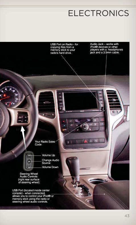
YOUR VEHICLE'S SOUND SYSTEM
ELECTRONICS
42
ELECTRONICS
43

Media Center 130 (Sales Code RES)
NOTE:• Your radio has many features that add to the comfort and convenience of
you and your passengers. Some of these radio features should not be usedwhen driving because they take your eyes from the road or your attentionfrom driving.
Clock Setting• Press and hold the “TIME” button until the hours blink; turn the
“TUNE/SCROLL” control knob to set the hours.
• Press the “TUNE/SCROLL” control knob until the minutes begin to blink;turn the “TUNE/SCROLL” control knob to set the minutes.
• Press the “TUNE/SCROLL” control knob to save the time change.
• To exit, press any button/knob or wait five seconds.
Equalizer, Balance And Fade• Press the “TUNE/SCROLL” control knob and BASS, MID, TREBLE,
BALANCE and FADE will display. Rotate the “TUNE/SCROLL” controlknob to select the desired setting.
ELECTRONICS
44
Radio Operation
Seek Up/Down Buttons• Press to seek through radio stations in AM, FM, or SAT bands.
• Hold either button to bypass stations without stopping.
Store Radio Presets• Press the “SET/RND” button once and SET 1 will show in the display.
Then select button (1–6).
• A second station may be added to each push button. Press the“SET/RND” button twice and SET 2 will show in the display. Then selectbutton (1–6).
CD/DISC Operation
Seek Up/Down Buttons• Press to seek through CD tracks.
• Hold either button to bypass tracks without stopping.
SET/RND Button (Random Play)• Press this button while the CD is playing to activate Random Play.
• This feature plays the selections on the CD in random order to provide aninteresting change of pace.
Audio Jack Operation• The Audio Jack allows a portable device, such as an MP3 player or a
cassette player, to be plugged into the radio and utilize the vehicle’saudio system, using a 3.5 mm audio cable, to amplify the source and playthrough the vehicle speakers.
• Pressing the “AUX” button will change the mode to auxiliary device if theAudio Jack is connected, allowing the music from your portable deviceto play through the vehicle's speakers.
• The functions of the portable device are controlled using the devicebuttons. The volume may be controlled using the radio or portabledevice.
ELECTRONICS
45
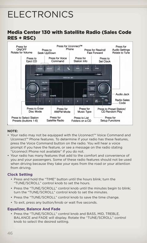
Media Center 130 with Satellite Radio (Sales CodeRES + RSC)
NOTE:• Your radio may not be equipped with the Uconnect™ Voice Command and
Uconnect™ Phone features. To determine if your radio has these features,press the Voice Command button on the radio. You will hear a voiceprompt if you have the feature, or see a message on the radio stating“Uconnect Phone not available” if you do not.
• Your radio has many features that add to the comfort and convenience ofyou and your passengers. Some of these radio features should not be usedwhen driving because they take your eyes from the road or your attentionfrom driving.
Clock Setting• Press and hold the “TIME” button until the hours blink; turn the
“TUNE/SCROLL” control knob to set the hours.
• Press the “TUNE/SCROLL” control knob until the minutes begin to blink;turn the “TUNE/SCROLL” control knob to set the minutes.
• Press the “TUNE/SCROLL” control knob to save the time change.
• To exit, press any button/knob or wait five seconds.
Equalizer, Balance And Fade• Press the “TUNE/SCROLL” control knob and BASS, MID, TREBLE,
BALANCE and FADE will display. Rotate the “TUNE/SCROLL” controlknob to select the desired setting.
ELECTRONICS
46
Radio Operation
Seek Up/Down Buttons• Press to seek through radio stations in AM, FM, or SAT bands.
• Hold either button to bypass stations without stopping.
Store Radio Presets• Press the “SET/RND” button once and SET 1 will show in the display.
Then select button (1–6).
• A second station may be added to each push button. Press the“SET/RND” button twice and SET 2 will show in the display. Then selectbutton (1–6).
Music Type• Press the “MUSIC TYPE” button to activate this mode. Press the “MUSIC
TYPE” button again or turn the “TUNE/SCROLL” control knob to selectthe desired music type (Adult Hits, Country, Jazz, Oldies, Rock, etc.).
• Once a music type is chosen and the icon is displayed, press either“SEEK” button and the radio will only search for stations with theselected music type.
NOTE: The Music Type function only operates when in FM mode.
SETUP Button• Pressing the “SETUP” button allows you to select between items that are
available in that particular mode.
• Turn the “TUNE/SCROLL” control knob to scroll through the entries.Push the “AUDIO/SELECT” button to select an entry and make changes.
Sirius XM™ Satellite Radio• Sirius XM™ Satellite Radio gives you over 130 channels, including 100%
commercial-free music from nearly every genre, plus all your favoritesports, news, talk and entertainment channels–all with crystal clear,coast-to-coast coverage, all in one place and all at your fingertips.
• To access Sirius XM™ Satellite Radio, press the “SAT” hard-key.
CD/DISC Operation
Seek Up/Down Buttons• Press to seek through CD tracks.
• Hold either button to bypass tracks without stopping.
SET/RND Button (Random Play)• Press this button while the CD is playing to activate Random Play.
• This feature plays the selections on the CD in random order to provide aninteresting change of pace.
ELECTRONICS
47

LIST Button• Press the “LIST” button to bring up a list of all folders on the CD. Scroll
up or down the list by turning the “TUNE/SCROLL” control knob.
• To select a folder from the list, press the “TUNE/SCROLL” control knoband the radio will begin playing the files contained in that folder.
Audio Jack Operation• The Audio Jack allows a portable device, such as an MP3 player or a
cassette player, to be plugged into the radio and utilize the vehicle’saudio system, using a 3.5 mm audio cable, to amplify the source and playthrough the vehicle speakers.
• Pressing the “AUX” button will change the mode to auxiliary device if theAudio Jack is connected, allowing the music from your portable deviceto play through the vehicle's speakers.
• The functions of the portable device are controlled using the devicebuttons. The volume may be controlled using the radio or portabledevice.
Media Center 430/430N (Sales Code RBZ/RHB)
NOTE:• Your radio may not be equipped with the Uconnect™ Voice Command and
Uconnect™ Phone features. To determine if your radio has these features,press the Voice Command button on the radio. You will hear a voiceprompt if you have the feature, or see a message on the radio stating“Uconnect Phone not available” if you do not.
ELECTRONICS
48

• Your radio has many features that add to the comfort and convenience ofyou and your passengers. Some of these radio features should not be usedwhen driving because they take your eyes from the road or your attentionfrom driving.
Clock Setting• Turn the radio on, then touch the screen where the time is displayed.
• Touch the “USER CLOCK” soft-key (Navigation radio only).
• To adjust the hours, touch either the “HOUR FORWARD” or “HOURBACKWARD” soft-key.
• To adjust the minutes, touch either the “MINUTE FORWARD” or “MINUTEBACKWARD” soft-key.
• To save the new time setting, touch the screen where the word “Save” isdisplayed.
Menu• Press the “MENU” hard-key to access the System Setup menu and the My
Files menu.
• Press the “MENU” hard-key in an active mode (SAT, CD, AUX, etc.) inorder to change mode specific settings.
Equalizer, Balance And FadeAudio Control Menu
• Press the “AUDIO” hard-key onthe right side of the radio.
• Use either the arrow soft-keys orthe cross-hair on the screen tochange Balance and Fade. The“CENTER” soft-key resets thesettings.
• Touch the “Equalizer” soft-key and use either the arrow soft-keys or thesliders on the screen to adjust BASS, MID, and/or TREBLE.
Display Settings• Press the “MENU” hard-key and
touch the “Display Settings”soft-key to access the DisplaySettings menu.
• Select the “Daytime Colors”soft-key to switch to manualdaytime mode and to adjust thebrightness of the display usingdaytime colors.
• Select the “Nighttime Colors” soft-key to switch to manual nighttimemode and to adjust the brightness of the display using nighttime colors.
ELECTRONICS
49

• Select the “Auto Color Mode” soft-key to switch to automaticdaytime/nighttime mode and to control the brightness of the displayusing the dimmer switch of the vehicle.
• Touch the “EXIT” soft-key to save your settings.
Radio Operation
• To access Radio Mode, touch the “RADIO” hard-key on the left side ofthe faceplate, then touch the “AM,” “FM” or “SAT” soft-key at the top ofthe screen to select the band.
Seek Up/Seek Down• Press the “Seek Up” or “Seek Down” soft-keys to seek through radio
stations in AM, FM, or SAT bands. Hold either Seek to bypass stationswithout stopping.
Store Radio Presets• Select the radio band by touching either the “AM,” “FM,” or “SAT”
soft-key.
• Find the station to store by either pressing the “Seek Up” or “SeekDown” soft-keys, touching the “SCAN” soft-key, or by using the “DIRECTTUNE” soft-key.
• Once the station is found, touch and hold one of the “PRESET” soft-keysin the list to the right, until you hear a confirmation beep.
NOTE: If the Presets are not visible on the right side of the screen, press the“Presets” soft-key.
ELECTRONICS
50

CD/DVD Disc Operation
• Press the “MEDIA” hard key to display the media source tabs at the topof the screen. Select the source by touching the “HDD,” “DISC,” or “AUX”media source soft-key tab.
NOTE: Your Touch-Screen Radio will usually automatically switch to theappropriate mode when something is first connected or inserted into thesystem.
Insert a CD/DVD Disc• To insert a disc, press the “LOAD” hard-key.
• With the printed side upwards, insert the disc into the disc slot of theradio. The radio pulls the disc in automatically and closes the flip screen.The radio selects the appropriate mode after the disc is recognized, andstarts playing the first track. The display shows “Reading...” during thisprocess.
Seek Up/Seek Down• Press the “Seek Up” or “Seek Down” soft-keys to seek through tracks in
Disc Mode. Hold either Seek to bypass tracks without stopping.
Audio Jack Operation• The Audio Jack allows a portable device, such as an MP3 player or a
cassette player, to be plugged into the radio and utilize the vehicle’saudio system, using a 3.5 mm audio cable, to amplify the source and playthrough the vehicle speakers.
ELECTRONICS
51
• Pressing the “MEDIA” hard-key and then the “AUX” soft-key to changethe mode to auxiliary device if the Audio Jack is connected, allowing themusic from your portable device to play through the vehicle's speakers.
• The functions of the portable device are controlled using the devicebuttons. The volume may be controlled using the radio or portabledevice.
Hard Disk Drive (HDD) Operation• The Hard Disk Drive (HDD) mode gives you access to the audio files on
the internal hard disk drive. It functions similar to a CD player, with theexception that the internal HDD can hold more tracks.
• It is also possible to import display pictures to the internal hard diskdrive. The pictures can be displayed on the right half of the radio screen.
• Before using the HDD mode, you will need to copy songs and pictures tothe internal hard drive. Songs and pictures can be added to the harddrive by using a CD or USB device (e.g. thumb drive or memory stick).
NOTE: WMA/MP3 Files and Selective Songs from a CD can also be addedto the HDD. See the Media Center 430/430N User's Manual for moreinformation.
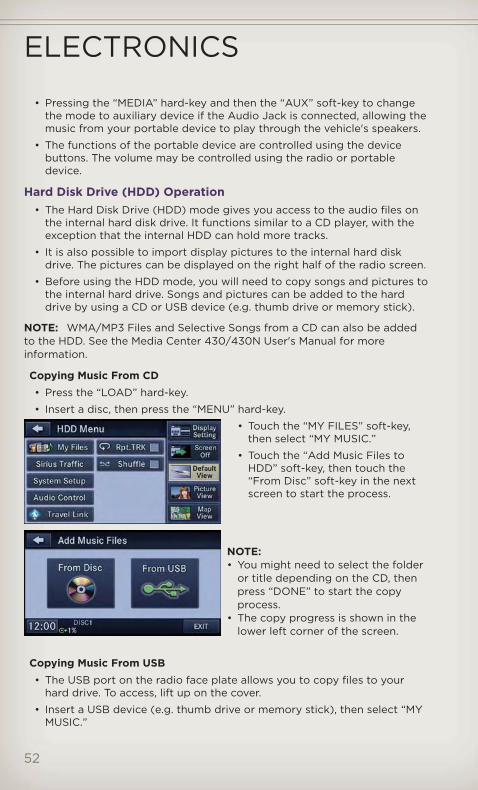
Copying Music From CD• Press the “LOAD” hard-key.
• Insert a disc, then press the “MENU” hard-key.
• Touch the “MY FILES” soft-key,then select “MY MUSIC.”
• Touch the “Add Music Files toHDD” soft-key, then touch the“From Disc” soft-key in the nextscreen to start the process.
NOTE:• You might need to select the folder
or title depending on the CD, thenpress “DONE” to start the copyprocess.
• The copy progress is shown in thelower left corner of the screen.
Copying Music From USB• The USB port on the radio face plate allows you to copy files to your
hard drive. To access, lift up on the cover.
• Insert a USB device (e.g. thumb drive or memory stick), then select “MYMUSIC.”
ELECTRONICS
52

• Touch the “Add Music Files to HDD” soft-key, then touch the “From USB”soft-key in the next screen.
• Select the folders or titles youwould like to copy, then touch the“DONE” soft-key to start the copyprocess.
NOTE: The copy progress is shown inthe lower left corner of the screen.
Copying Pictures To The HDD• Insert either a CD or a USB device containing your pictures in JPEG
format.
• Press the “MY FILES” hard-key.
• Touch the “My Pictures” soft-key to get an overview of the currentlystored images, then touch the “Add” soft-key.
• Touch the “From Disc” or “FromUSB” soft-key, then select thefolders or pictures you wish tocopy to the HDD. Use the “PAGE”soft-keys to page through the listof pictures.
• Touch the desired pictures or press the “All” soft-key for all pictures.Confirm your selections by touching the “SAVE” soft key.
NOTE: The copy progress is shown in the lower left corner of the screen.
Display a Picture on the Radio Screen• Once the import is complete, the pictures will then be available in the
“MY PICTURES” screen.
• Press the “MY FILES” hard-key, then touch the “My Pictures” soft-key.Touch the desired picture, then touch the “Set as Picture View” soft-keyand then touch the “Exit” soft-key. Lastly press the “MENU” hard-key andthen touch the “Picture View” soft-key to display the chosen picture onthe radio screen.
NOTE:• A check mark in the My Pictures screen indicates the currently used
picture.• You can also delete pictures by touching the “Delete” soft-key.
ELECTRONICS
53
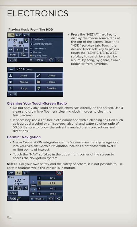
Playing Music From The HDD• Press the “MEDIA” hard key to
display the media source tabs atthe top of the screen. Touch the“HDD” soft-key tab. Touch thedesired track soft-key to play ortouch the “SEARCH/BROWSE”soft-key to search by artist, byalbum, by song, by genre, from afolder, or from Favorites.
Cleaning Your Touch-Screen Radio• Do not spray any liquid or caustic chemicals directly on the screen. Use a
clean and dry micro fiber lens cleaning cloth in order to clean thetouch-screen.
• If necessary, use a lint-free cloth dampened with a cleaning solution suchas isopropyl alcohol or an isopropyl alcohol and water solution ratio of50:50. Be sure to follow the solvent manufacturer's precautions anddirections.
Garmin® Navigation• Media Center 430N integrates Garmin’s consumer-friendly navigation
into your vehicle. Garmin Navigation includes a database with over 6million points of interest.
• Touch the “NAV” soft-key in the upper right corner of the screen toaccess the Navigation system.
NOTE: For your own safety and the safety of others, it is not possible to usecertain features while the vehicle is in motion.
ELECTRONICS
54

Main Navigation Menu
Finding Points Of Interest• From the main Navigation menu,
touch “Where To?,” then touch“Points of Interest.”
• Select a Category and then asubcategory, if necessary.
• Select your destination and touch“Go.”
Finding A Place By Spelling The Name• From the Main Navigation Menu, touch “Where to?,” then touch “Points
of Interest” and then touch “Spell Name.”
• Enter the name of your destination.
• Touch “Done.”
• Select your destination and touch “Go.”
Entering A Destination Address• From the main Navigation menu, touch “Where To?,” then touch
“Address.”
• Follow the on-screen prompts to enter the address and touch “Go.”
Searching Near Another Location• From the main Navigation menu, touch “Where To?,” then touch a
destination and then touch “Near.”
• Select an option from the available choices.
Setting Your Home Location• From the main Navigation menu, touch “Where To?,” then touch “Go
Home.”
• You may enter your address directly, use your current location as yourhome address, or choose from recently found locations.
Edit Home Location• From the main Navigation menu, touch “Where To?,” then touch
“Favorites.”
• Next, touch the location you would like to edit, then touch “Press forMore,” and then “Edit.”
Go Home• A Home location must be saved in the system. From the Main Navigation
menu, touch “Where To?,” then touch “Go Home.”
ELECTRONICS
55
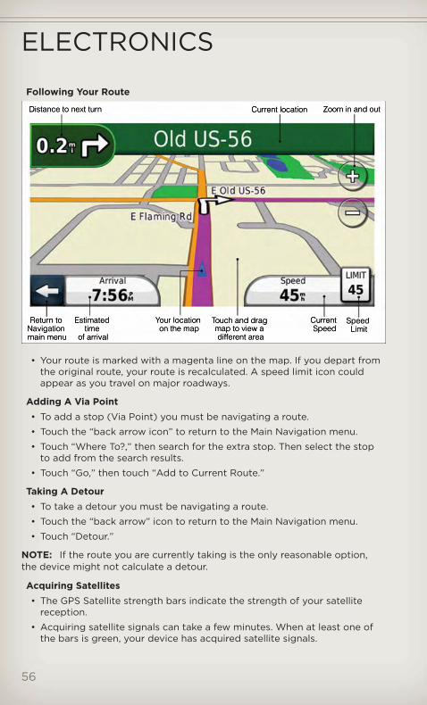
Following Your Route
• Your route is marked with a magenta line on the map. If you depart fromthe original route, your route is recalculated. A speed limit icon couldappear as you travel on major roadways.
Adding A Via Point• To add a stop (Via Point) you must be navigating a route.
• Touch the “back arrow icon” to return to the Main Navigation menu.
• Touch “Where To?,” then search for the extra stop. Then select the stopto add from the search results.
• Touch “Go,” then touch “Add to Current Route.”
Taking A Detour• To take a detour you must be navigating a route.
• Touch the “back arrow” icon to return to the Main Navigation menu.
• Touch “Detour.”
NOTE: If the route you are currently taking is the only reasonable option,the device might not calculate a detour.
Acquiring Satellites• The GPS Satellite strength bars indicate the strength of your satellite
reception.
• Acquiring satellite signals can take a few minutes. When at least one ofthe bars is green, your device has acquired satellite signals.
ELECTRONICS
56

• You may experience delays in acquisition of satellite signals when inareas with an obstructed view to the sky, such as garages, tunnels, orlarge cities with tall buildings.
Media Center 730N (Sales Code RHR)
NOTE: Your radio may not be equipped with the Uconnect™ VoiceCommand and Uconnect™ Phone features. To determine if your radio hasthese features, press the Voice Command button on the radio. You will hear avoice prompt if you have the feature, or see a message on the radio stating“Uconnect Phone not available” if you do not.
• Your radio has many features that add to the comfort and convenienceof you and your passengers. Some of these radio features should not beused when driving because they take your eyes from the road or yourattention from driving.
Clock Setting• Turn the radio on, then touch the screen where the time is displayed.
• Touch the “USER CLOCK” soft-key.
• To adjust the hours, touch either the “HOUR FORWARD” or “HOURBACKWARD” soft-key.
• To adjust the minutes, touch either the “MINUTE FORWARD” or “MINUTEBACKWARD” soft-key.
• To save the new time setting, touch the screen where the word “Save” isdisplayed.
ELECTRONICS
57
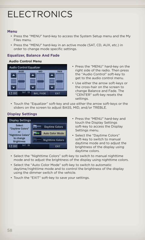
Menu• Press the “MENU” hard-key to access the System Setup menu and the My
Files menu.
• Press the “MENU” hard-key in an active mode (SAT, CD, AUX, etc.) inorder to change mode specific settings.
Equalizer, Balance And FadeAudio Control Menu
• Press the “MENU” hard-key on theright side of the radio. Then pressthe “Audio Control” soft-key toget to the audio control menu.
• Use either the arrow soft-keys orthe cross-hair on the screen tochange Balance and Fade. The“CENTER” soft-key resets thesettings.
• Touch the “Equalizer” soft-key and use either the arrow soft-keys or thesliders on the screen to adjust BASS, MID, and/or TREBLE.
Display Settings• Press the “MENU” hard-key and
touch the Display Settingssoft-key to access the DisplaySettings menu.
• Select the “Daytime Colors”soft-key to switch to manualdaytime mode and to adjust thebrightness of the display usingdaytime colors.
• Select the “Nighttime Colors” soft-key to switch to manual nighttimemode and to adjust the brightness of the display using nighttime colors.
• Select the “Auto Color Mode” soft-key to switch to automaticdaytime/nighttime mode and to control the brightness of the displayusing the dimmer switch of the vehicle.
• Touch the “EXIT” soft-key to save your settings.
ELECTRONICS
58

Radio Operation
• To access Radio Mode, touch the “RADIO/MEDIA” hard-key on the leftside of the faceplate repeatedly until AM/FM/SAT appears at the top ofthe screen, then touch the “AM,” “FM” or “SAT” soft-key to select theband.
Seek Up/Seek Down• Press the “Seek Up” or “Seek Down” hard-keys to seek through radio
stations in AM, FM, or SAT bands. Hold either Seek to bypass stationswithout stopping.
Store Radio Presets• Select the radio band by touching either the “AM,” “FM,” or “SAT”
soft-key.
• Find the station to store by either pressing the “Seek Up” or “SeekDown” hard-keys, touching the “SCAN” soft-key, or by using the “DIRECTTUNE” soft-key.
• Once the station is found, touch and hold one of the PRESET soft-keys inthe list to the right, until you hear a confirmation beep.
NOTE: If the Presets are not visible on the right side of the screen, press the“Presets” soft-key.
ELECTRONICS
59
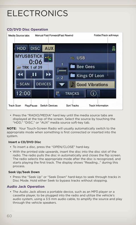
CD/DVD Disc Operation
• Press the “RADIO/MEDIA” hard key until the media source tabs aredisplayed at the top of the screen. Select the source by touching the“HDD,” “DISC,” or “AUX” media source soft-key tab.
NOTE: Your Touch-Screen Radio will usually automatically switch to theappropriate mode when something is first connected or inserted into thesystem.
Insert a CD/DVD Disc• To insert a disc, press the “OPEN/CLOSE” hard-key.
• With the printed side upwards, insert the disc into the disc slot of theradio. The radio pulls the disc in automatically and closes the flip screen.The radio selects the appropriate mode after the disc is recognized, andstarts playing the first track. The display shows “Reading...” during thisprocess.
Seek Up/Seek Down• Press the “Seek Up” or “Seek Down” hard-keys to seek through tracks in
Disc Mode. Hold either Seek to bypass tracks without stopping.
Audio Jack Operation• The Audio Jack allows a portable device, such as an MP3 player or a
cassette player, to be plugged into the radio and utilize the vehicle’saudio system, using a 3.5 mm audio cable, to amplify the source and playthrough the vehicle speakers.
ELECTRONICS
60

• Pressing the “RADIO/MEDIA” hard-key and then the “AUX” soft-key tochange the mode to auxiliary device if the Audio Jack is connected,allowing the music from your portable device to play through thevehicle's speakers.
• The functions of the portable device are controlled using the devicebuttons. The volume may be controlled using the radio or portabledevice.
Hard Disk Drive (HDD) Operation• The Hard Disk Drive (HDD) mode gives you access to the audio files on
the internal hard disk drive. It functions similar to a CD player, with theexception that the internal HDD can hold more tracks.
• It is also possible to import display pictures to the internal hard diskdrive. The pictures can be displayed on the right half of the radio screen.
• Before using the HDD mode, you will need to copy songs and pictures tothe internal hard drive. Songs and pictures can be added to the harddrive by using a CD or USB device (e.g. thumb drive or memory stick).
NOTE: WMA/MP3 Files and Selective Songs from a CD can also be addedto the HDD. See the Media Center 730N User's Manual for more information.
Copying Music From CD• Press the “OPEN/CLOSE” hard-key.
• Insert a disc, then press the “MENU” hard-key.
• Touch the “MY FILES” soft-key,then select “MY MUSIC.”
• Touch the “Add Music Files toHDD” soft-key, then touch the“From Disc” soft-key in the nextscreen to start the process.
NOTE:• You might need to select the folder
or title depending on the CD, thenpress “Done” to start the copyprocess.
• The copy progress is shown in thelower left corner of the screen.
Copying Music From USB• The USB port on the radio face plate allows you to copy files to your
hard drive. To access, lift up on the cover.
• Insert a USB device (e.g. thumb drive or memory stick), then select “MYFILES”.
ELECTRONICS
61

• Touch the “MY MUSIC” soft-key,then touch the “Add Music Files”to HDD soft-key.
• Touch “From USB” soft-key, thenselect the folders or titles youwould like to copy, and then touchthe “SAVE” soft-key to start thecopy process.
NOTE: The copy progress is shown inthe lower left corner of the screen.
Copying Pictures To The HDD• Insert either a CD or a USB device containing your pictures in JPEG
format.
• Press the “MENU” hard-key to access the Settings Menu, then touch the“My Files” soft-key.
• Touch the “My Pictures” soft-key to get an overview of the currentlystored images, then touch the “Add” soft-key.
• Touch the “From Disc” or “FromUSB” soft-key, then select thefolders or pictures you wish tocopy to the HDD. Use the “PAGE”soft-keys to page through the listof pictures.
• Touch the desired pictures or press the “All” soft-key for all pictures.Confirm your selections by touching the “SAVE” soft key.
NOTE: The copy progress is shown in the lower left corner of the screen.
Display a Picture on the Radio Screen• Once the import is complete, the pictures will then be available in the
“MY PICTURES” screen.
ELECTRONICS
62
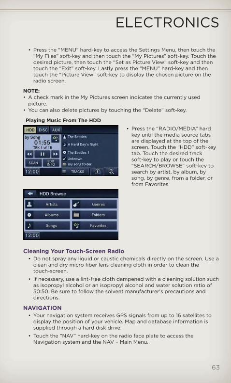
• Press the “MENU” hard-key to access the Settings Menu, then touch the“My Files” soft-key and then touch the “My Pictures” soft-key. Touch thedesired picture, then touch the “Set as Picture View” soft-key and thentouch the “Exit” soft-key. Lastly press the “MENU” hard-key and thentouch the “Picture View” soft-key to display the chosen picture on theradio screen.
NOTE:• A check mark in the My Pictures screen indicates the currently used
picture.• You can also delete pictures by touching the “Delete” soft-key.
Playing Music From The HDD• Press the “RADIO/MEDIA” hard
key until the media source tabsare displayed at the top of thescreen. Touch the “HDD” soft-keytab. Touch the desired tracksoft-key to play or touch the“SEARCH/BROWSE” soft-key tosearch by artist, by album, bysong, by genre, from a folder, orfrom Favorites.
Cleaning Your Touch-Screen Radio• Do not spray any liquid or caustic chemicals directly on the screen. Use a
clean and dry micro fiber lens cleaning cloth in order to clean thetouch-screen.
• If necessary, use a lint-free cloth dampened with a cleaning solution suchas isopropyl alcohol or an isopropyl alcohol and water solution ratio of50:50. Be sure to follow the solvent manufacturer's precautions anddirections.
NAVIGATION• Your navigation system receives GPS signals from up to 16 satellites to
display the position of your vehicle. Map and database information issupplied through a hard disk drive.
• Touch the “NAV” hard-key on the radio face plate to access theNavigation system and the NAV – Main Menu.
ELECTRONICS
63
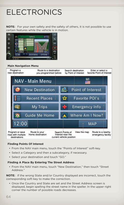
NOTE: For your own safety and the safety of others, it is not possible to usecertain features while the vehicle is in motion.
Main Navigation Menu
Finding Points Of Interest• From the NAV main menu, touch the “Points of Interest” soft-key.
• Select a Category and then a subcategory, if necessary.
• Select your destination and touch “GO.”
Finding A Place By Entering The Street Address• From the NAV main menu, touch “New Destination,” then touch “Street
Address.”
NOTE: If the wrong State and/or Country displayed are incorrect, touch thecorresponding soft-key to make the correction.
• Once the Country and State are set and the Street Address screen isdisplayed, begin spelling the street name in the speller. In the upper rightcorner the number of possible roads decreases.
ELECTRONICS
64

• Touch the “LIST” soft-key to display a list of possible street names. Selectthe correct street name.
• Next input the number.
• In the Confirm Route screen the navigation radio displays the completeaddress, a map of the destination area, and the current routing methodfor you to verify.
• Touch the “GO” soft-key to activate the route guidance.
Entering Your Home Location• Press the “NAV” hard-key on the right side of the radio.
• From the Nav – Main Menu, touch “Guide Me Home” to enter your homeaddress. If no home address has been set, touch “YES” to access theEnter Home Address menu.
• Touch “Street Address” to enter your address. Touch the soft-key withyour state’s name and enter your street name into the speller.
• Once the street name has been input, touch “CONTINUE” to confirm.Enter the house number into the next screen. If more than one city hasthis address, you will then need to select your city from a list.
• Once the address is entered completely, the system shows a map of yourhome address area. Touch “SAVE” to confirm the address. The systemwill then ask if you want to go there, yes or no.
Change Home Address• This procedure will allow you to change your Home Address if one has
already been entered.
• Press the “MENU” hard-key, touch “My Files” and then touch “MyAddress Book.”
• Touch “Home,” then touch “Edit Contacts” and then “Change Address.”
• Touch the soft-key with your state’s name and enter your street nameinto the speller.
• Once the street name has been input, touch “CONTINUE” to confirm.
• Enter the house number into the next screen. If more than one city hasthis address, you will then need to select your city from a list.
• Touch the “SAVE” soft-key to confirm the address.
Go Home• From the NAV main menu, touch “Guide Me Home” when you want to
route to your home destination.
Where Am I Now?• From the NAV main menu, touch “Where Am I Now?.” The Where Am I
Now? menu displays location information for the current vehicle position.
• Touch the “NEARBY POI”soft-key to search for a local Point of Interest.
• Touch the “SAVE LOCATION” soft-key to save the current location in theSaved Locations memory.
ELECTRONICS
65

Route Guidance
• After starting route guidance, the system calculates the route andannounces: “Follow the arrows on the display.” You will receivenavigation recommendations by voice messages and screen displays.
Route Options• After pressing the “OPTIONS” soft-key in the Route Guidance Menu, the
following information is displayed:
• In the left half of the screen, the current position and the current routingmethod are displayed.
• “Take Detour” will allow you to calculate a different route.
• “Find Nearby POI” to search for a local POI.
• “Destination Info” displays destination information.
• “View Turn List” lists streets utilized for the current route.
• “Save Destination” to save the destination address.
• “Change Method” will allow you to change the routing method.
ELECTRONICS
66

Sirius XM™ SATELLITE RADIO/TRAVEL LINK• The following describes features that are available when in Sirius XM™
Satellite Radio mode.
• To access Sirius XM™ Satellite Radio, press the “RADIO/MEDIA” or“RADIO” and then touch the “SAT” soft-key tab.
Info• Touch the “i” soft-key to view detailed information about the current
Sirius XM™ Satellite channel.
Sirius XM™ Parental Controls• Sirius XM™ offers the option to permanently block selected channels. Call
1-888-539-7474 and request the Family Package.
• Media Center 430/430N and 730N: Press the “MENU” hard-key while inSirius XM™ Satellite Radio Mode, then touch the “Channel Lock” toenable and/or disable desired channels. The SEEK and SCAN functionwill then only display channels without Channel lock.
Search/Browse• Touch the “magnifying glass”
soft-key to search/browse theSirius XM™ channel listing byFavorites and Categories such asSong, Artist and Channel Name.The Search/Browse also allowsyou manage your Favorites.
Sirius XM™ Satellite Radio Favorites(SAT Favorites)• You can save 50 favorite songs
and 50 favorite artists.
• Touch the “add favorite” soft-keyto add either the song or the artistof the currently playing programto the SAT Favorites list.
• You will see a favorite star indicator in the lower left side of the screenand a pop up will alert you that a favorite song or artist is currentlyplaying on one of the Sirius XM™ satellite radio channels.
NOTE: Refer to your Media Center730N or Media Center 430/430NUser's Manual for more information.
ELECTRONICS
67

Display SAT Favorites List• Touch the “Search/Browse” soft-key and select “Favorites” from the SAT
Browse screen.
• Touch the desired favoritessoft-key to switch the SAT tunerto the corresponding channel.
• You may use the “LIST” soft-key totoggle between:
• Favorite Songs.
• Favorite Artists.
• Currently playing favorites.
Replay• While you are in SAT mode, you
can replay 44 minutes of thecurrent Sirius XM™ channel (whenthe channel is changed, this audiobuffer is erased). Press theREPLAY button to listen to thestored audio.
• You can touch the on-screen controls to pause and rewind audioplayback, touch the SCAN button to preview each of the tracks stored inthe buffer, or select a track from the list.
• The time displayed below the bar indicates how much time is presentbetween the current buffer play position and the live broadcast.
ReplayOption
Option Description
Play/Pause Touch to Pause content playback. Touch Pause/Play againto resume playback.
Rewind/RW Rewinds the channel content in steps of 5 seconds. Touchand hold to rewind continuously, then release to beginplaying content at that point.
FastForward/FW
Forwards the content, and works similarly to Rewind/RW.However, Fast Forward/FW can only be used when contenthas been previously rewound.
ELECTRONICS
68

ReplayOption
Option Description
Replay Time Displays the amount of time in the upper center of thescreen by which your content lags the Live channel.
Live Resumes playback of Live content at any time whilereplaying rewound content.
Sirius Travel Link (Media Center 730N (RHR) & Media Center 430N(RHB) Only)
• Sirius Travel Link brings a wealth of useful information into your vehicleand right to your fingertips.
• To access Travel Link, press the MENU hard-key, then the Travel Linksoft-key.
NOTE:• Sirius Travel Link requires a subscription, sold separately after the 1 year
trial subscription included with your vehicle purchase.• Sirius Travel Link is only available in the United States.
1 – Favorites View and store your favorite location, theater andsport teams for quick access.
2 – Forecast View detailed weather conditions, forecasts andski/snowboarding conditions at local resorts.
3 – Ski Info View ski and snowboarding conditions at local skiresorts.
4 – Fuel Prices View detailed price information for fuel stations nearyour current location.
5 – Movies View information on movies that are playing attheaters near your current location.
6 – Sports View sports scores and upcoming events for all majorsports.
ELECTRONICS
69
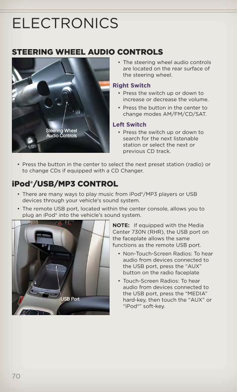
STEERING WHEEL AUDIO CONTROLS• The steering wheel audio controls
are located on the rear surface ofthe steering wheel.
Right Switch• Press the switch up or down to
increase or decrease the volume.
• Press the button in the center tochange modes AM/FM/CD/SAT.
Left Switch• Press the switch up or down to
search for the next listenablestation or select the next orprevious CD track.
• Press the button in the center to select the next preset station (radio) orto change CDs if equipped with a CD Changer.
iPod®/USB/MP3 CONTROL• There are many ways to play music from iPod®/MP3 players or USB
devices through your vehicle's sound system.
• The remote USB port, located within the center console, allows you toplug an iPod® into the vehicle's sound system.
NOTE: If equipped with the MediaCenter 730N (RHR), the USB port onthe faceplate allows the samefunctions as the remote USB port.
• Non-Touch-Screen Radios: To hearaudio from devices connected tothe USB port, press the “AUX”button on the radio faceplate
• Touch-Screen Radios: To hearaudio from devices connected tothe USB port, press the “MEDIA”hard-key, then touch the “AUX” or“iPod®” soft-key.
ELECTRONICS
70

• When connected to this feature:
• The iPod® can be controlled usingthe radio buttons to Play, Browse,and List the iPod® or externaldevices contents.
• The iPod® battery charges whenplugged into the USB port (ifsupported by the specific audiodevice).
• Compatible iPod® devices may also be controllable using voicecommands. Refer to the Owner's Manual on the DVD for details.
NOTE:• The USB port supports certain Mini, Classic, Nano, Touch, and iPhone®
devices. The USB port also supports playing music from compatibleexternal USB Mass Storage Class memory devices. For supported audio fileformats, refer to the USB Port section in the Owner's Manual on the DVD.Refer to www.UconnectPhone.com website for a list of tested iPod®s. SomeiPod® software versions may not fully support the USB port features.Please visit Apple’s website for iPod® software updates.
WARNING!Do not plug in or remove the iPod® or external device while driving.Failure to follow this warning could result in a collision.
Uconnect™ Phone• To determine if your vehicle is equipped with Uconnect™ Phone, press
the “Uconnect™ Phone” button . If your vehicle has this feature, aftera couple seconds you will hear a voice prompt. If not, you will see amessage on the radio “Uconnect phone not available”.
• The Uconnect™ Phone is a voice-activated, hands-free, in-vehiclecommunications system with Voice Command Capability (see VoiceCommand section).
NOTE: To access the tutorial, press the “Uconnect™ Phone” button .After the BEEP, say “tutorial”. Press any hard-key/button or touch the display(Touch-Screen radio) to cancel the tutorial.
• The Uconnect™ Phone allows you to dial a phone number with yourmobile phone using simple voice commands.
• Refer to your vehicle Owner's Manual on the DVD for further details.
NOTE: The Uconnect™ Phone requires a mobile phone equipped with theBluetooth® Hands-Free Profile, Version 1.0 or higher. For Uconnect™ customersupport, call 1–877–855–8400 or visit www.UconnectPhone.com.
ELECTRONICS
71
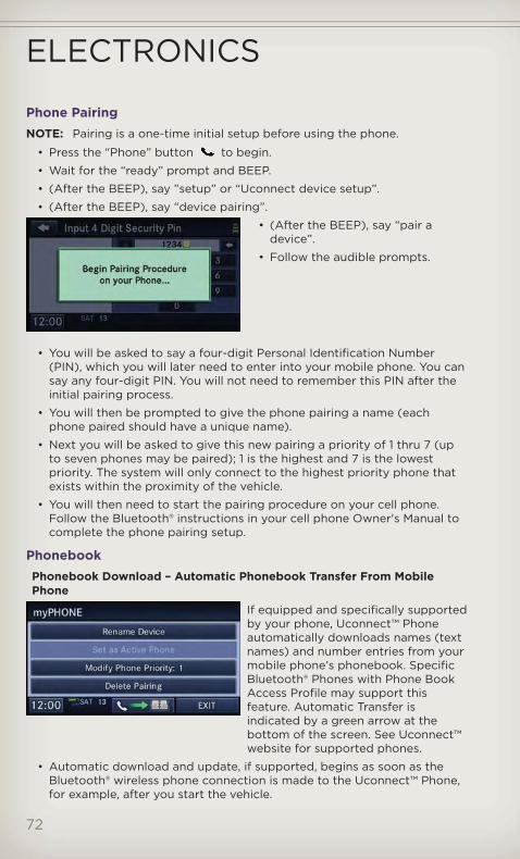
Phone PairingNOTE: Pairing is a one-time initial setup before using the phone.
• Press the “Phone” button to begin.
• Wait for the “ready” prompt and BEEP.
• (After the BEEP), say ”setup” or “Uconnect device setup”.
• (After the BEEP), say “device pairing”.
• (After the BEEP), say “pair adevice”.
• Follow the audible prompts.
• You will be asked to say a four-digit Personal Identification Number(PIN), which you will later need to enter into your mobile phone. You cansay any four-digit PIN. You will not need to remember this PIN after theinitial pairing process.
• You will then be prompted to give the phone pairing a name (eachphone paired should have a unique name).
• Next you will be asked to give this new pairing a priority of 1 thru 7 (upto seven phones may be paired); 1 is the highest and 7 is the lowestpriority. The system will only connect to the highest priority phone thatexists within the proximity of the vehicle.
• You will then need to start the pairing procedure on your cell phone.Follow the Bluetooth® instructions in your cell phone Owner's Manual tocomplete the phone pairing setup.
PhonebookPhonebook Download – Automatic Phonebook Transfer From MobilePhone
If equipped and specifically supportedby your phone, Uconnect™ Phoneautomatically downloads names (textnames) and number entries from yourmobile phone’s phonebook. SpecificBluetooth® Phones with Phone BookAccess Profile may support thisfeature. Automatic Transfer isindicated by a green arrow at thebottom of the screen. See Uconnect™website for supported phones.
• Automatic download and update, if supported, begins as soon as theBluetooth® wireless phone connection is made to the Uconnect™ Phone,for example, after you start the vehicle.
ELECTRONICS
72
• A maximum of 1000 entries per phone will be downloaded and updatedevery time a phone is connected to the Uconnect™ Phone.
• Depending on the maximum number of entries downloaded, there maybe a short delay before the latest downloaded names can be used. Untilthen, if available, the previously downloaded phonebook is available foruse.
• Only the phonebook of the currently connected mobile phone isaccessible.
• Only the mobile phone’s phonebook is downloaded. SIM cardphonebook is not part of the Mobile phonebook.
• This downloaded phonebook cannot be edited or deleted on theUconnect™ Phone. These can only be edited on the mobile phone. Thechanges are transferred and updated to Uconnect™ Phone on the nextphone connection.
Phonebook Edit• Press the “Phone” button .
• (After the BEEP), say “phonebook”.
• (After the BEEP), say “new entry” or “list names” or “delete”.
• Follow the prompts.
Making A Phone Call• Press the “Phone” button .
• (After the BEEP), say “dial” (or “call” a name).
• (After the BEEP), say number (or name).
Receiving A Call – Accept (And End)• When an incoming call rings/is announced on Uconnect™, press the
Phone button .
• To end a call, press the Phone button .
Mute (Or Unmute) Microphone During Call• During a call, press the “Voice Command” button .
• (After the BEEP), say “mute” (or “mute off”).
Transfer Ongoing Call Between Handset And Vehicle• During a call, press the “Voice Command” button .
• (After the BEEP), say “transfer call”.
Changing The Volume• Start a dialogue by pressing the “Phone” button , then adjust the
volume during a normal call.
• Use the radio ON/OFF VOLUME rotary knob to adjust the volume to acomfortable level while the Uconnect™ system is speaking. Please notethe volume setting for Uconnect™ is different than the audio system.
ELECTRONICS
73

WARNING!• Any voice commanded system should be used only in safe driving
conditions following local laws and phone use. All attention shouldbe kept on the roadway ahead. Failure to do so may result in acollision causing you and others to be severely injured or killed.
• In an emergency, to use Uconnect™ Phone, your mobile phone mustbe:• turned on,• paired to Uconnect™ Phone,• and have network coverage.
Uconnect™ VOICE COMMAND• The Uconnect™ Voice Command system allows you to control your AM,
FM radio, satellite radio, disc player, HDD, Uconnect™ Phone, a memorecorder, and supported portable media devices.
• When you press the “Voice Command” button located on theradio faceplate or steering wheel, you will hear a beep. The beep is yoursignal to give a command. If you do not say a command within a fewseconds, the system will present you with a list of options. If you everwish to interrupt the system while it lists options, press the “VoiceCommand” button , listen for the BEEP, and say your command.
Voice Command Operation• Start a dialogue by pressing the
“Voice Command” button ,you will hear a beep. The beep isyour signal to give a command.Below are a list of voicecommands for each of thedifferent modes.
Common Voice Commands (Examples)
Main Menu “Radio” (to switch to the radio mode)“Disc” (to switch to the disc mode)“Memo” (to switch to the memo recorder)“System Setup” (to switch to system setup)
Radio Mode “Frequency” (to change the frequency)“Next Station” (to select the next station)“Previous Station” (to select the previous station)“Radio Menu” (to switch to the radio menu)“Main Menu” (to switch to the main menu)
ELECTRONICS
74

Sirius XM™Satellite RadioMode
“Channel Number” (to change the channel by its spokennumber)“Next Channel” (to select the next channel)“Previous Channel” (to select the previous channel)“List Channel” (to hear a list of available channels)“Select Name” (to say the name of a channel)“Radio Menu” (to switch to the radio menu)“Main Menu” (to switch to the main menu)
Disc Mode “Track” (#) (to change the track)“Next Track” (to play the next track)“Previous Track” (to play the previous track)“Main Menu” (to switch to the main menu)
Memo Mode To switch to the voice recorder mode, say “Memo”. Thefollowing are common voice commands for this mode:“New Memo” (to record a new memo) — During therecording, you may press the Voice Command button
to stop recording. You proceed by saying one ofthe following commands:— “Save” (to save the memo)— “Continue” (to continue recording)— “Delete” (to delete the recording)— “Play Memos” (to play previously recorded memos) —During the playback you may press the Voice Commandbutton
to stop playing memos. You proceed by sayingone of the following commands:— “Repeat” (to repeat a memo)— “Next” (to play the next memo)— “Previous” (to play the previous memo)— “Delete” (to delete a memo)— “Delete All” (to delete all memos)
SMS (Text Messaging)• If equipped with Uconnect™ Voice Command, your Media Center 430N &
730N radios may be able to play incoming Short Message Service (SMS)messages (text messages) through the vehicle's sound system.
• It also allows you to respond by selecting from various pre-definedphrases.
• Not all phones are compatible with this feature. Refer to the phonecompatibility list at www.UconnectPhone.com. Connected mobilephones must be bluetooth-compatible, and paired with your radio.
• Press the “Voice Command” button and after the BEEP, say“SMS” to get started.
NOTE: To access the tutorial, press the “Voice Command” button .After the BEEP, say “tutorial”. Press any hard-key/button or touch the display(Touch-Screen radio) to cancel the tutorial.
ELECTRONICS
75
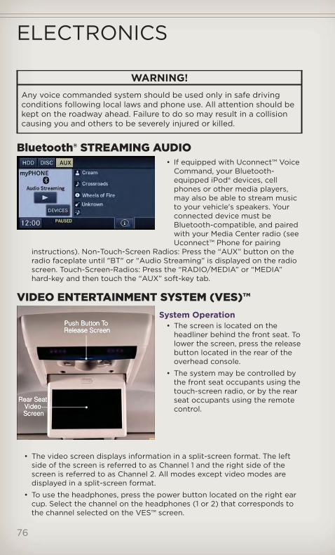
WARNING!Any voice commanded system should be used only in safe drivingconditions following local laws and phone use. All attention should bekept on the roadway ahead. Failure to do so may result in a collisioncausing you and others to be severely injured or killed.
Bluetooth® STREAMING AUDIO• If equipped with Uconnect™ Voice
Command, your Bluetooth-equipped iPod® devices, cellphones or other media players,may also be able to stream musicto your vehicle's speakers. Yourconnected device must beBluetooth-compatible, and pairedwith your Media Center radio (seeUconnect™ Phone for pairing
instructions). Non-Touch-Screen Radios: Press the “AUX” button on theradio faceplate until "BT" or “Audio Streaming” is displayed on the radioscreen. Touch-Screen-Radios: Press the “RADIO/MEDIA” or “MEDIA”hard-key and then touch the “AUX” soft-key tab.
VIDEO ENTERTAINMENT SYSTEM (VES)™System Operation
• The screen is located on theheadliner behind the front seat. Tolower the screen, press the releasebutton located in the rear of theoverhead console.
• The system may be controlled bythe front seat occupants using thetouch-screen radio, or by the rearseat occupants using the remotecontrol.
• The video screen displays information in a split-screen format. The leftside of the screen is referred to as Channel 1 and the right side of thescreen is referred to as Channel 2. All modes except video modes aredisplayed in a split-screen format.
• To use the headphones, press the power button located on the right earcup. Select the channel on the headphones (1 or 2) that corresponds tothe channel selected on the VES™ screen.
ELECTRONICS
76

Operation Of The Touch-Screen Radio• To view a DVD video, press the OPEN/CLOSE or LOAD hard-key and
insert the disc. Playback will begin automatically after the DVD isrecognized by the disc drive. If playback does not begin automatically,follow these steps:
• Press the MENU hard-key, then touch the Rear VES™ soft-key. If achapter list appears on the right side of the screen touch the HIDE LISTsoft-key to display the Rear VES™ Control screen.
• Touch the 1 soft-key to select an audio channel, then touch the DISCsoft-key in the MEDIA column.
Operation Of The Remote• The remote control operates similarly to any DVD remote you have used
before and allows the rear seat passengers to change stations, tracks,discs and audio/video modes.
• The remote control is designed to control either channel by using theselector switch located on the right side of the remote.
• Pressing the power button will turn the VES™ system ON/OFF.
• Pressing the MODE button causes the Mode Selection menu to appearon the VES™ screen. Use the remote control arrow buttons to scrollthrough the available modes, then press ENTER to select the desiredmode.
Auxiliary Audio/Video Input Jacks• The Aux jacks are located on the rear of the center console.
• Connect the video game or other external media devices to the AUXjacks following the color coding for VES™ jacks.
• Using either the touch-screen radio or remote control, select AUX fromthe Rear VES™ Control or Mode Selection screen.
• Refer to your vehicle's Owners Manual on the DVD for further details.
ELECTRONICS
77

ELECTRONIC VEHICLE INFORMATION CENTER(EVIC)
• The EVIC features a driverinteractive display that is locatedin the instrument cluster. Pressingthe controls on the left side of thesteering wheel allows the driver toselect vehicle information andPersonal Settings. For additionalinformation, refer toProgrammable Features in thisguide.
• Press and release the UPbutton to scroll upward throughthe main menus (Fuel Economy,Vehicle Info, Tire PSI, Cruise,Messages, Units, System Setup)and sub menus.
• Press and release the DOWN button to scroll downward through themain menus and sub menus.
• Press and release the SELECT button for access to main menus, submenus or to select a personal setting in the setup menu.
• Press the BACK button to scroll back to a previous menu or sub menu.
Compass Calibration• This compass is self-calibrating, which eliminates the need to set the
compass manually. When the vehicle is new, the compass may appearerratic and the EVIC will display “CAL” until the compass is calibrated.
• You may also calibrate the compass by completing one or more 360degree turns (in an area free from large metal or metallic objects) untilthe “CAL” message displayed in the EVIC turns off. The compass will nowfunction normally.
ECO• The ECO message will appear in your EVIC display whenever you are
driving in a fuel efficient manner.
• This feature allows you to monitor when you are driving in a fuel efficientmanner, and it can be used to modify driving habits in order to increasefuel economy.
ELECTRONICS
78

PROGRAMMABLE FEATURESElectronic Vehicle Information Center (EVIC)
• The EVIC can be used to program the following Personal Settings. Pressthe UP or DOWN button until System Setup displays, then pressthe SELECT button. Scroll through the settings using the UP orDOWN buttons. Press the SELECT button to change the setting.Press the BACK button to scroll back to a previous menu or sub menu.
• Select Language • Illuminated Approach• Nav – Turn By Turn • Display ECO Symbol• Auto Unlock Doors • Keyless Enter-N-Go™• Remote Unlock Sequence • Auto High Beams• RKE Linked To Memory • Wiper Mode• Remote Start Comfort Sys. • Hill Start Assist (HSA)• Horn With Remote Lock • Blind Spot Alert• Horn With Remote Start • Forward Collision Warning• Flash Lamps With Lock • Park Assist System• Headlamp Off Delay • Display Units of Measure In:• Headlamps With Wipers • Liftgate Chime• Easy Entry/Exit Seat • Calibrate Compass• Tilt Mirror in Reverse • Compass Variance• Key-Off Power Delay
UNIVERSAL GARAGE DOOR OPENER (HomeLink®)• HomeLink® replaces up to three hand-held transmitters that operate
devices such as garage door openers, motorized gates, lighting or homesecurity systems. The HomeLink® unit is powered by your vehicles 12 Voltbattery.
• The HomeLink® buttons that are located in the overhead console orsunvisor designate the three different HomeLink® channels.
• The HomeLink® indicator is located above the center button.
Before You Begin ProgrammingHomeLink®
• Be sure that your vehicle is parkedoutside of the garage before youbegin programming.
• For more efficient programmingand accurate transmission of theradio-frequency signal it isrecommended that a new batterybe placed in the hand-heldtransmitter of the device that isbeing programmed to theHomeLink® system.
ELECTRONICS
79

• Erase all channels before you begin programming. To erase the channels,place the ignition switch into the ON/RUN position, then press and holdthe two outside HomeLink® buttons (I and III) for up 20 seconds or untilthe red indicator flashes.
NOTE:• Erasing all channels should only be performed when programming
HomeLink® for the first time. Do not erase channels when programmingadditional buttons.
• If you have any problems, or require assistance, please call toll-free1–800–355–3515 or, on the Internet at www.HomeLink.com for informationor assistance.
Programming A Rolling Code• For programming Garage Door Openers that were manufactured after
1995. These Garage Door Openers can be identified by the “LEARN” or“TRAIN” button located where the hanging antenna is attached to theGarage Door Opener. It is NOT the button that is normally used to openand close the door. The name and color of the button may vary bymanufacturer.
• Place the ignition switch into the ON/RUN position.
• Place the hand-held transmitter 1 to 3 in (3 to 8 cm) away from theHomeLink® button you wish to program while keeping the HomeLink®indicator light in view.
• Simultaneously press and hold both the HomeLink® button you want toprogram and the hand-held transmitter button.
• Continue to hold both buttons and observe the indicator light. TheHomelink® indicator will flash slowly and then rapidly after Homelink® hasreceived the frequency signal from the hand-held transmitter. Releaseboth buttons after the indicator light changes from slow to rapid.
• At the garage door opener motor (in the garage), locate the “LEARN” or“TRAINING” button. This can usually be found where the hangingantenna wire is attached to the garage door opener motor. Firmly pressand release the “LEARN” or “TRAINING” button.
NOTE: You have 30 seconds in which to initiate the next step after theLEARN button has been pressed.
• Return to the vehicle and press the programmed HomeLink® buttontwice (holding the button for two seconds each time). If the device isplugged in and activates, programming is complete.
NOTE: If the device does not activate, press the button a third time (for twoseconds) to complete the training.
• To program the remaining two HomeLink® buttons, repeat each step foreach remaining button. DO NOT erase the channels.
ELECTRONICS
80

Programming A Non-Rolling Code• For programming Garage Door Openers manufactured before 1995.
• Turn the ignition switch to the ON/RUN position.
• Place the hand-held transmitter 1 to 3 in (3 to 8 cm) away from theHomeLink® button you wish to program while keeping the HomeLink®indicator light in view.
• Simultaneously press and hold both the HomeLink® button you want toprogram and the hand-held transmitter button.
• Continue to hold both buttons and observe the indicator light. TheHomelink® indicator will flash slowly and then rapidly after Homelink® hasreceived the frequency signal from the hand-held transmitter. Releaseboth buttons after the indicator light changes from slow to rapid.
• Press and hold the programmed HomeLink® button and observe theindicator light.
NOTE:• If the indicator light stays on constantly, programming is complete and the
garage door (or device) should activate when the HomeLink® button ispressed.
• To program the two remaining HomeLink® buttons, repeat each step foreach remaining button. DO NOT erase the channels.
Using HomeLink®• To operate, press and release the programmed HomeLink® button.
Activation will now occur for the programmed device (i.e., garage dooropener, gate operator, security system, entry door lock, home/officelighting, etc.,). The hand-held transmitter of the device may also be usedat any time.
WARNING!• Your motorized door or gate will open and close while you are
programming the universal transceiver. Do not program thetransceiver if people or pets are in the path of the door or gate.
• Do not run your vehicle in a closed garage or confined area whileprogramming the transceiver. Exhaust gas from your vehiclecontains Carbon Monoxide (CO) which is odorless and colorless.Carbon Monoxide is poisonous when inhaled and can cause you andothers to be severely injured or killed.
ELECTRONICS
81
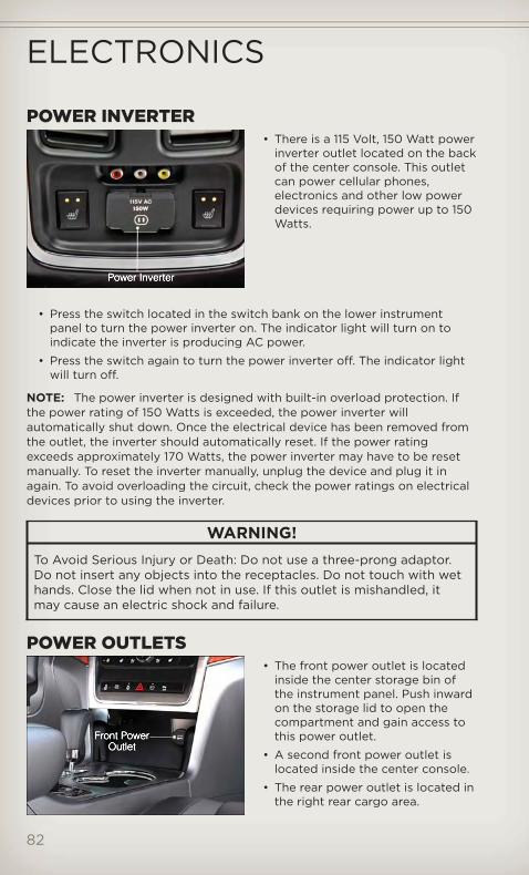
POWER INVERTER• There is a 115 Volt, 150 Watt power
inverter outlet located on the backof the center console. This outletcan power cellular phones,electronics and other low powerdevices requiring power up to 150Watts.
• Press the switch located in the switch bank on the lower instrumentpanel to turn the power inverter on. The indicator light will turn on toindicate the inverter is producing AC power.
• Press the switch again to turn the power inverter off. The indicator lightwill turn off.
NOTE: The power inverter is designed with built-in overload protection. Ifthe power rating of 150 Watts is exceeded, the power inverter willautomatically shut down. Once the electrical device has been removed fromthe outlet, the inverter should automatically reset. If the power ratingexceeds approximately 170 Watts, the power inverter may have to be resetmanually. To reset the inverter manually, unplug the device and plug it inagain. To avoid overloading the circuit, check the power ratings on electricaldevices prior to using the inverter.
WARNING!To Avoid Serious Injury or Death: Do not use a three-prong adaptor.Do not insert any objects into the receptacles. Do not touch with wethands. Close the lid when not in use. If this outlet is mishandled, itmay cause an electric shock and failure.
POWER OUTLETS• The front power outlet is located
inside the center storage bin ofthe instrument panel. Push inwardon the storage lid to open thecompartment and gain access tothis power outlet.
• A second front power outlet islocated inside the center console.
• The rear power outlet is located inthe right rear cargo area.
ELECTRONICS
82

• The power outlets are labeled with either a “key” or a “battery” symbolto indicate how the outlet is powered. Power outlets labeled with a “key”are powered when the ignition switch is in the ON/RUN or ACC position,while the outlets labeled with a “battery” are connected directly to thebattery and powered at all times.
NOTE:• Do not exceed the maximum power of 160 Watts (13 Amps) at 12 Volts. If
the 160 Watt (13 Amp) power rating is exceeded, the fuse protecting thesystem will need to be replaced.
• Power outlets are designed for accessory plugs only. Do not insert anyother object in the power outlet as this will damage the outlet and blowthe fuse. Improper use of the power outlet can cause damage not coveredby your new vehicle warranty.
• The rear cargo power outlet can be switched to “battery” powered all thetime by switching the power outlet right rear quarter panel fuse in the fusepanel.
ELECTRONICS
83

QUADRA-TRAC I® FOUR-WHEEL DRIVEQuadra-Trac I® Operating Instructions/Precautions - 3.6L Only
• The Quadra-Trac I® is a single-speed (HI range only) transfer case, whichprovides convenient full-time four-wheel drive. No driver interaction isrequired. The Brake Traction Control (BTC) System, which combinesstandard ABS and Traction Control, provides resistance to any wheel thatis slipping to allow additional torque transfer to wheels with traction.
QUADRA-TRAC II®/QUADRA-DRIVE II®FOUR-WHEEL DRIVEQuadra-Trac II®/Quadra-Drive II® Operating Instructions/Precautions
• The Quadra-Trac II®/Quadra-DriveII® transfer case is fully automaticin the normal driving 4WD HImode. The Quadra-TracII®/Quadra-Drive II® transfer caseprovides three mode positions:
• 4WD HI
• NEUTRAL
• 4WD LOW
• This transfer case is fullyautomatic in the 4WD HI mode.
• When additional traction is required, the 4WD LOW position can be usedto lock the front and rear driveshafts together and force the front andrear wheels to rotate at the same speed. The 4WD LOW position isintended for loose, slippery surfaces only. Driving in the 4WD LOWposition on dry, hard-surfaced roads may cause increased tire wear anddamage to driveline components.
• When operating your vehicle in 4WD LOW, the engine speed isapproximately three times that of the 4WD HI position at a given roadspeed. Take care not to overspeed the engine and do not exceed 25 mph(40 km/h).
NOTE:• If shift conditions/interlocks are not met, or a transfer case motor
temperature protection condition exists, a “For 4x4 Low Slow Below5 MPH or 8 KPH Put Trans in N Press 4 Low” message will flash from theElectronic Vehicle Information Center (EVIC).
OFF-ROAD CAPABILITIES
84

Shifting Procedures4WD HI To 4WD LOW• With the vehicle at speeds of 0 to 3 mph (0 to 5 km/h), the ignition
switch in the ON/RUN position or the engine running, shift thetransmission into NEUTRAL, and press the “4WD LOW” button once onthe transfer case switch. The “4WD LOW” indicator light in theinstrument cluster will begin to flash and remain on solid when the shiftis complete.
4WD LOW To 4WD HI• With the vehicle at speeds of 0 to 3 mph (0 to 5 km/h), the ignition
switch in the ON/RUN position or the engine running, shift thetransmission into NEUTRAL, and press the “4WD LOW” button once onthe transfer case switch. The “4WD LOW” indicator light in theinstrument cluster will flash and turn off when the shift is complete.
NOTE:• If the shift conditions/interlocks are not met, or a transfer case motor
temperature protection exists, a “For 4x4 Low Slow Below 5 MPH or 8 KPHPut Trans in N Press 4 Low” message will flash on the Electronic VehicleInformation Center (EVIC).
• Shifting into or out of 4WD LOW is possible with the vehicle completelystopped; however, difficulty may occur due to the mating clutch teeth notbeing properly aligned. Several attempts may be required for clutch teethalignment and shift completion to occur. The preferred method is with thevehicle rolling 0 to 3 mph (0 to 5 km/h). If the vehicle is moving faster than3 mph (5 km/h), the transfer case will not allow the shift.
NEUTRAL Shift Procedure• Turn the ignition switch to the ON/RUN position, engine off.
• Vehicle stopped, with foot on brake.
• Place the transmission into NEUTRAL.
• Press and hold the NEUTRAL button located near the 4WD mode controlknob with a pen or similar object for four seconds. The indicator light willbegin to flash indicating the shift is in progress. The light will stopblinking (stay on solid) when the NEUTRAL shift is complete. A “4WDSYSTEM IN NEUTRAL” message will display on the Electronic VehicleInformation Center (EVIC).
• Repeat these Steps to shift out of NEUTRAL.
OFF-ROAD CAPABILITIES
85

SELEC-TERRAIN™• Selec-Terrain™ combines the capabilities of the vehicle control systems,
along with driver input, to provide the best performance for all terrains.
Rotate the mode control knob to select the following Selec-Terrain™positions:
• Sport – Dry weather, on-road calibration. Only available in 4WD Highrange. Performance-based tuning that provides a rear wheel drive feelbut with improved handling and acceleration over a two-wheel drivevehicle. The Electronic Stability Control will set to allow more drivercontrol of the vehicle while maintaining safe handling controls. Thevehicle will lower (if equipped with Air Suspension) by 0.59 inches(15 mm) in the SPORT mode.
• Snow – The Electronic Stability Control is set for additional stability ininclement weather. Use on and off road on loose traction surfaces suchas snow.
• Auto – Fully automatic full-time four-wheel drive operation can be usedon and off road. Balances traction with steering feel to provide improvedhandling and acceleration over two-wheel drive vehicles.
• Sand/Mud – Off-road calibration for use on low traction surfaces such asmud, sand, or wet grass. Driveline is maximized for traction. Somebinding may be felt on less forgiving surfaces. The electronic brakecontrols are set to limit traction control management of throttle andwheel spin.
• Rock – Off-road calibration only available in 4WD Low range. The vehicleis raised (if equipped with Air Suspension) for improved groundclearance. Traction based tuning with improved steer-ability for use onhigh traction off-road surfaces. Activates the Hill Descent Control forsteep downhill control. Use for low speed obstacles such as large rocks,deep ruts, etc.
Quadra-Lift™• The Quadra-Lift™ air suspension
system provides full time loadleveling capability along with thebenefit of being able to adjustvehicle height by the push of abutton. Quadra-Lift™ is availablewith both Quadra-Trac II® andQuadra-Drive II™.
• The system requires that theengine be running for all changes.When lowering the vehicle all ofthe doors, including the liftgate,must be closed.
OFF-ROAD CAPABILITIES
86
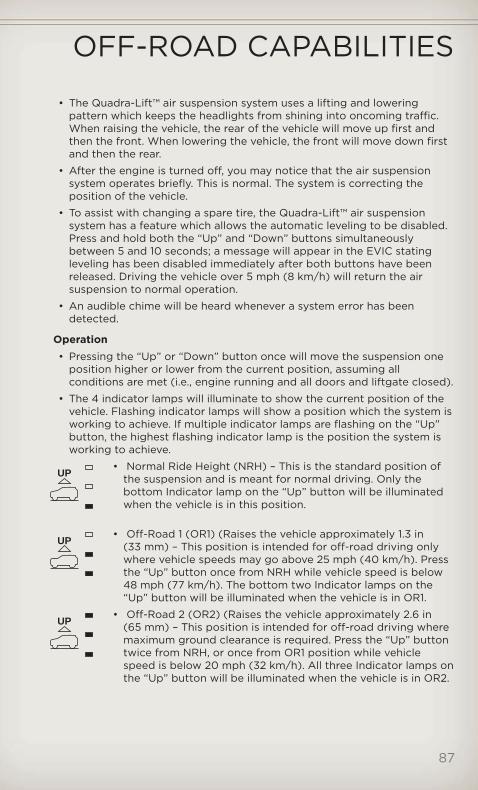
• The Quadra-Lift™ air suspension system uses a lifting and loweringpattern which keeps the headlights from shining into oncoming traffic.When raising the vehicle, the rear of the vehicle will move up first andthen the front. When lowering the vehicle, the front will move down firstand then the rear.
• After the engine is turned off, you may notice that the air suspensionsystem operates briefly. This is normal. The system is correcting theposition of the vehicle.
• To assist with changing a spare tire, the Quadra-Lift™ air suspensionsystem has a feature which allows the automatic leveling to be disabled.Press and hold both the “Up” and “Down” buttons simultaneouslybetween 5 and 10 seconds; a message will appear in the EVIC statingleveling has been disabled immediately after both buttons have beenreleased. Driving the vehicle over 5 mph (8 km/h) will return the airsuspension to normal operation.
• An audible chime will be heard whenever a system error has beendetected.
Operation• Pressing the “Up” or “Down” button once will move the suspension one
position higher or lower from the current position, assuming allconditions are met (i.e., engine running and all doors and liftgate closed).
• The 4 indicator lamps will illuminate to show the current position of thevehicle. Flashing indicator lamps will show a position which the system isworking to achieve. If multiple indicator lamps are flashing on the “Up”button, the highest flashing indicator lamp is the position the system isworking to achieve.
• Normal Ride Height (NRH) – This is the standard position ofthe suspension and is meant for normal driving. Only thebottom Indicator lamp on the “Up” button will be illuminatedwhen the vehicle is in this position.
• Off-Road 1 (OR1) (Raises the vehicle approximately 1.3 in(33 mm) – This position is intended for off-road driving onlywhere vehicle speeds may go above 25 mph (40 km/h). Pressthe “Up” button once from NRH while vehicle speed is below48 mph (77 km/h). The bottom two Indicator lamps on the“Up” button will be illuminated when the vehicle is in OR1.
• Off-Road 2 (OR2) (Raises the vehicle approximately 2.6 in(65 mm) – This position is intended for off-road driving wheremaximum ground clearance is required. Press the “Up” buttontwice from NRH, or once from OR1 position while vehiclespeed is below 20 mph (32 km/h). All three Indicator lamps onthe “Up” button will be illuminated when the vehicle is in OR2.
UP
UP
UP
OFF-ROAD CAPABILITIES
87

• Park Mode (Lowers the vehicle approximately 1.5 in (38 mm) –This position lowers the vehicle for easier passenger entry andexit. Press the “Down” button once from NRH while the vehiclespeed is below 25 mph (40 km/h). Once the vehicle speedgoes below 15 mph (24 km/h) the vehicle height will begin tolower. The Indicator lamp on the “Down” button will beilluminated when the vehicle is in Park Mode.
WARNING!• You or others could be injured if you leave the vehicle unattended
with the transfer case in the N (Neutral) position without first fullyengaging the parking brake. The transfer case N (Neutral) positiondisengages both the front and rear driveshafts from the powertrainand will allow the vehicle to move regardless of the transmissionposition. The parking brake should always be applied when thedriver is not in the vehicle.
• The air suspension system uses a high pressure volume of air tooperate the system. To avoid personal injury or damage to thesystem, see your authorized dealer for service.
Hill Start Assist/Hill Descent Control• The Hill Start Assist system assists the driver when starting a vehicle
from a stop on a hill.
• The Hill Descent Control system maintains vehicle speed whiledescending hills during off-road driving situations and is available in4WD HIGH range and 4WD LOW range.
• Refer to your Owner's Manual on the DVD for further details.
DOWN
PARK
OFF-ROAD CAPABILITIES
88
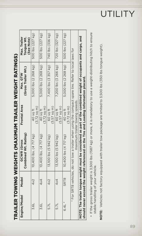
TRA
ILER
TOW
ING
WEI
GH
TS(M
AX
IMU
MTR
AIL
ERW
EIG
HT
RA
TIN
GS)
Eng
ine/
Mo
del
Mo
del
GC
WR
(Gro
ssC
om
bin
edW
t.R
atin
g)
Fro
ntal
Are
aM
ax.G
TW(G
ross
Trai
ler
Wt.
)M
ax.T
raile
rTo
ngue
Wt.
(See
No
te)
3.6
L4
x210
,40
0lb
s.(4
717
kg)
40
sqft
(3.7
2sq
m)
5,0
00
lbs
(226
8kg
)50
0lb
s(2
27kg
)
3.6
L4
x410
,40
0lb
s.(4
717
kg)
40
sqft
(3.7
2sq
m)
5,0
00
lbs
(226
8kg
)50
0lb
s(2
27kg
)
5.7L
4x2
13,10
0lb
s(5
94
2kg
)6
0sq
ft(5
.57
sqm
)7,
40
0lb
s(3
357
kg)
740
lbs
(336
kg)
5.7L
4x4
13,10
0lb
s(5
94
2kg
)6
0sq
ft(5
.57
sqm
)7,
200
lbs
(326
6kg
)72
0lb
s(3
27kg
)
6.4
L*
SR
T8
10,4
00
lbs
(471
7kg
)4
0sq
ft(3
.72
sqm
)5,
00
0lb
s(2
268
kg)
500
lbs
(227
kg)
*F
or
SR
T8
vehi
cles
,do
not
tow
atr
aile
rw
hen
usin
gth
eco
mp
act
spar
eti
re.R
efer
tolo
call
aws
for
max
imum
trai
ler
tow
ing
spee
ds.
NO
TE:T
hetr
aile
rto
ngue
wei
ght
mus
tb
eco
nsid
ered
asp
art
of
the
com
bin
edw
eig
hto
fo
ccup
ants
and
carg
o,an
dsh
oul
dne
ver
exce
edth
ew
eig
htre
fere
nced
on
the
Tire
and
Load
ing
Info
rmat
ion
pla
card
.
•If
the
gro
sstr
aile
rw
eig
htis
3,50
0lb
s(1
587
kg)
or
mo
re,i
tis
man
dat
ory
tous
ea
wei
ght
-dis
trib
utin
ghi
tch
toen
sure
stab
leha
ndlin
go
fyo
urve
hicl
e.
NO
TE:
Veh
icle
sno
tfa
cto
ryeq
uip
ped
wit
htr
aile
rto
wp
acka
ge
are
limit
edto
3,50
0lb
s(3
50lb
sto
ngue
wei
ght
).
UTILITY
89
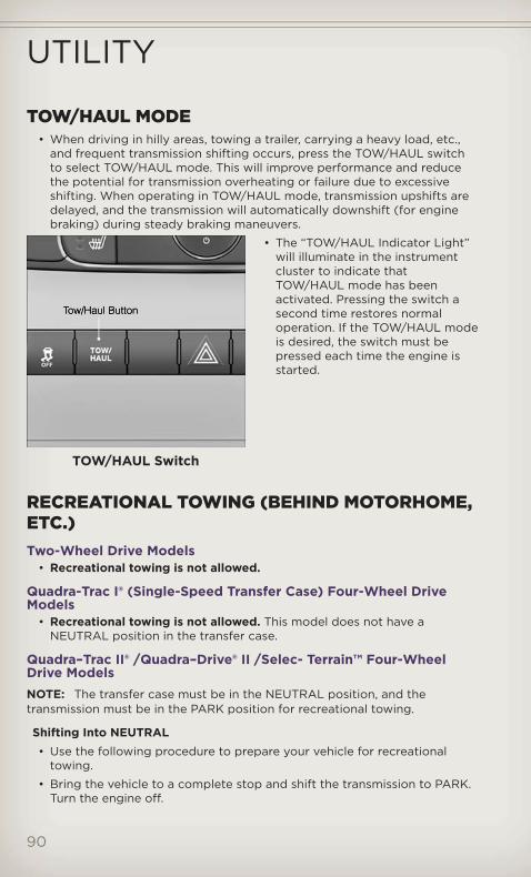
TOW/HAUL MODE• When driving in hilly areas, towing a trailer, carrying a heavy load, etc.,
and frequent transmission shifting occurs, press the TOW/HAUL switchto select TOW/HAUL mode. This will improve performance and reducethe potential for transmission overheating or failure due to excessiveshifting. When operating in TOW/HAUL mode, transmission upshifts aredelayed, and the transmission will automatically downshift (for enginebraking) during steady braking maneuvers.
• The “TOW/HAUL Indicator Light”will illuminate in the instrumentcluster to indicate thatTOW/HAUL mode has beenactivated. Pressing the switch asecond time restores normaloperation. If the TOW/HAUL modeis desired, the switch must bepressed each time the engine isstarted.
RECREATIONAL TOWING (BEHIND MOTORHOME,ETC.)Two-Wheel Drive Models
• Recreational towing is not allowed.
Quadra-Trac I® (Single-Speed Transfer Case) Four-Wheel DriveModels
• Recreational towing is not allowed. This model does not have aNEUTRAL position in the transfer case.
Quadra–Trac II® /Quadra–Drive® II /Selec- Terrain™ Four-WheelDrive ModelsNOTE: The transfer case must be in the NEUTRAL position, and thetransmission must be in the PARK position for recreational towing.
Shifting Into NEUTRAL• Use the following procedure to prepare your vehicle for recreational
towing.
• Bring the vehicle to a complete stop and shift the transmission to PARK.Turn the engine off.
TOW/HAUL Switch
UTILITY
90

• For vehicles with Keyless Enter-N-Go™, remove the Keyless Enter-N-Go™button and use the Key Fob to complete this procedure.
• Turn the ignition switch to the ON/RUN position, but do not start theengine.
• Press and hold the brake pedal and shift the transmission into NEUTRAL.
• Using a ballpoint pen or similar object, press and hold the recessedtransfer case N (Neutral) button for four seconds, until the light next tothe N symbol starts to blink, indicating shift in progress. The light willstop blinking (stay on solid) when the shift to N (Neutral) is complete. A“FOUR WHEEL DRIVE SYSTEM IN NEUTRAL” message will display onthe EVIC (Electronic Vehicle Information Center).
• Start the engine and shift the transmission into REVERSE.
• Release the brake pedal for five seconds and ensure that there is novehicle movement.
• Turn the engine off and firmly apply the parking brake.
• Shift the transmission into PARK and remove the Key Fob.
• Attach the vehicle to the tow vehicle using a suitable tow bar and releasethe parking brake.
NOTE: Vehicles equipped with Quadra-Lift™ must be lowered to the “Park”(lowest) level, and have automatic leveling disabled, before tying them down(from the body) on a trailer or a flatbed truck. Refer to “Quadra-Lift™” in“Off-Road Capabilities” for more information. If the vehicle cannot belowered to the “Park” level (for example, engine will not run), tie-downs mustbe fastened to the axles (not the body). Failure to follow these instructionsmay cause fault codes to be set and/or loss of proper tie-down tension.
CAUTION!• Towing with the rear wheels on the ground will cause severe
transmission damage. Damage from improper towing is not coveredunder the New Vehicle Limited Warranty.
• Front or rear wheel lifts should not be used. Internal damage to thetransmission or transfer case will occur if a front or rear wheel lift isused when recreational towing.
• It is necessary to follow these steps to be certain that the transfercase is fully in NEUTRAL before recreational towing to preventdamage to internal parts.
UTILITY
91
WARNING!You or others could be injured if you leave the vehicle unattendedwith the transfer case in the NEUTRAL position without first fullyengaging the parking brake. The transfer case NEUTRAL positiondisengages both the front and rear driveshafts from the powertrainand will allow the vehicle to move even if the transmission is in PARK.The parking brake should always be applied when the driver is not inthe vehicle.
UTILITY
92
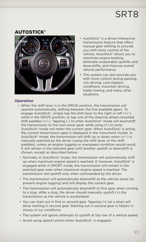
AUTOSTICK®• AutoStick® is a driver-interactive
transmission feature that offersmanual gear shifting to provideyou with more control of thevehicle. AutoStick® allows you tomaximize engine braking,eliminate undesirable upshifts anddownshifts, and improve overallvehicle performance.
• This system can also provide youwith more control during passing,city driving, cold slipperyconditions, mountain driving,trailer towing, and many othersituations.
Operation• When the shift lever is in the DRIVE position, the transmission will
operate automatically, shifting between the five available gears. Toengage AutoStick®, simply tap the shift lever to the right or left (+/-)while in the DRIVE position, or tap one of the steering wheel-mountedshift paddles (+/-). Tapping (-) to enter AutoStick® mode will downshiftthe transmission to the next lower gear, while using (+) to enterAutoStick® mode will retain the current gear. When AutoStick® is active,the current transmission gear is displayed in the instrument cluster. InAutoStick® mode, the transmission will shift up or down when (+/-) ismanually selected by the driver (using the shift lever, or the shiftpaddles), unless an engine lugging or overspeed condition would result.It will remain in the selected gear until another upshift or downshift ischosen, except as described below:
• Normally, in AutoStick® mode, the transmission will automatically shiftup when maximum engine speed is reached. If, however, AutoStick® isengaged while in SPORT mode, the transmission will remain in theselected gear even when maximum engine speed is reached. Thetransmission will upshift only when commanded by the driver.
• The transmission will automatically downshift as the vehicle slows (toprevent engine lugging) and will display the current gear.
• The transmission will automatically downshift to first gear when comingto a stop. After a stop, the driver should manually upshift (+) thetransmission as the vehicle is accelerated.
• You can start out in first or second gear. Tapping (+) (at a stop) willallow starting in second gear. Starting out in second gear is helpful insnowy or icy conditions.
• The system will ignore attempts to upshift at too low of a vehicle speed.
• Avoid using speed control when AutoStick® is engaged.
SRT8
93

• Transmission shifting will be more noticeable when AutoStick® isengaged.
• To disengage AutoStick® mode, hold the shift lever to the right or pressand hold the (+) shift paddle until “D” is once again displayed in theinstrument cluster. You can shift in or out of the AutoStick® mode at anytime without taking your foot off the accelerator pedal.
WARNING!Do not downshift for additional engine braking on a slippery surface.The drive wheels could lose their grip and the vehicle could skid,causing a collision or personal injury.
SELEC-TRACK™• Selec-Track™ combines the capabilities of the vehicle control systems,
along with driver input, to provide the best performance for all terrains.
• Rotate the mode control knob toselect the following Selec-Track™positions:
• Sport – Dry weather, on-roadcalibration. Performance basedtuning that provides a rear wheeldrive feel but with improvedhandling and acceleration over atwo-wheel drive vehicle. Theactive suspension system will bein Semi Firm mode, and a greenflag will light up in the instrumentcluster.
• Snow – Tuning set for additional stability in inclement weather. Use onand off road on loose traction surfaces such as snow.
• Auto – Fully automatic full time four-wheel drive operation can be usedon and off road. This position balances traction with seamless steeringfeel to provide improved handling and acceleration over two-wheeldrive vehicles.
• Track – This position offers track road calibration for use on hightraction surfaces. Driveline is maximized for traction. Some binding maybe felt on less forgiving surfaces.
• Tow – Use this mode for towing. Vehicle suspension will go to Firmmode and peak power will be limited in the engine controls.
SRT8
94
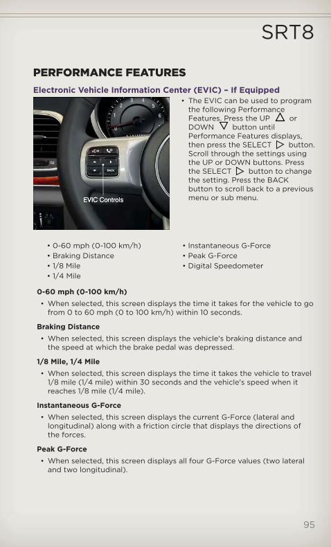
PERFORMANCE FEATURESElectronic Vehicle Information Center (EVIC) – If Equipped
• The EVIC can be used to programthe following PerformanceFeatures. Press the UP orDOWN button untilPerformance Features displays,then press the SELECT button.Scroll through the settings usingthe UP or DOWN buttons. Pressthe SELECT button to changethe setting. Press the BACKbutton to scroll back to a previousmenu or sub menu.
• 0-60 mph (0-100 km/h) • Instantaneous G-Force• Braking Distance • Peak G-Force• 1/8 Mile • Digital Speedometer• 1/4 Mile
0-60 mph (0-100 km/h)• When selected, this screen displays the time it takes for the vehicle to go
from 0 to 60 mph (0 to 100 km/h) within 10 seconds.
Braking Distance• When selected, this screen displays the vehicle's braking distance and
the speed at which the brake pedal was depressed.
1/8 Mile, 1/4 Mile• When selected, this screen displays the time it takes the vehicle to travel
1/8 mile (1/4 mile) within 30 seconds and the vehicle's speed when itreaches 1/8 mile (1/4 mile).
Instantaneous G-Force• When selected, this screen displays the current G-Force (lateral and
longitudinal) along with a friction circle that displays the directions ofthe forces.
Peak G-Force• When selected, this screen displays all four G-Force values (two lateral
and two longitudinal).
SRT8
95

Digital Speedometer• When selected, this screen displays vehicle speed and records top speed.
WARNING!Measurement of vehicle statistics with the Performance Features isintended for off-highway or off-road use only and should not be doneon any public roadways. It is recommended that these features beused in a controlled environment and within the limits of the law. Thecapabilities of the vehicle as measured by the performance pagesmust never be exploited in a reckless or dangerous manner, which canjeopardize the user’s safety or the safety of others. Only a safe,attentive, and skillful driver can prevent accidents.
SUMMER/THREE-SEASON TIRES• This vehicle may be equipped with wheels and tires to enhance traction
in both wet and dry conditions.
• Summer tires are not intended to be driven in snow or on ice.
• Use summer tires only in sets of four.
NOTE: Summer tires will not contain the all season designation ormountain/snowflake symbol on the sidewall of the tire.
WARNING!Do not use summer tires in snow/ice conditions. You could losecontrol, resulting in severe injury or death.
SRT8
96

24-HOUR TOWING ASSISTANCE• Dial toll-free 1-800-521-2779 or 1-800-363-4869 for Canadian residents.
• Provide your name, vehicle identification number and license platenumber.
• Provide your location, including telephone number, from which you arecalling.
• Briefly describe the nature of the problem and answer a few simplequestions.
• You will be given the name of the service provider and an estimated timeof arrival. If you feel you are in an “unsafe situation”, please let us know.With your consent, we will contact local police or safety authorities.
INSTRUMENT CLUSTER WARNING LIGHTS- Tire Pressure Monitoring System (TPMS) Light
• Each tire, including the spare (if provided), should be checked monthly,when cold and inflated to the inflation pressure recommended by thevehicle manufacturer on the vehicle placard or tire inflation pressurelabel. (If your vehicle has tires of a different size than the size indicatedon the vehicle placard or tire inflation pressure label, you shoulddetermine the proper tire inflation pressure for those tires.)
• As an added safety feature, your vehicle has been equipped with a TirePressure Monitoring System (TPMS) that illuminates a low tire pressuretelltale when one or more of your tires is significantly under-inflated.Accordingly, when the low tire pressure telltale illuminates, you shouldstop and check your tires as soon as possible, and inflate them to theproper pressure. Driving on a significantly under-inflated tire causes thetire to overheat and can lead to tire failure. Under-inflation also reducesfuel efficiency and tire tread life, and may affect the vehicle’s handlingand stopping ability.
• IF THE LIGHT STARTS FLASHING INDICATING A LOW TIRE PRESSURE,ADJUST THE AIR PRESSURE IN THE LOW TIRE TO THE AIR PRESSURESHOWN ON THE VEHICLE PLACARD OR TIRE INFLATION PRESSURELABEL LOCATED ON THE DRIVER'S DOOR. NOTE: AFTER INFLATION,THE VEHICLE MAY NEED TO BE DRIVEN FOR 20 MINUTES BEFORETHE FLASHING LIGHT WILL TURN OFF.
• Please note that the TPMS is not a substitute for proper tiremaintenance, and it is the driver’s responsibility to maintain correct tirepressure, even if under-inflation has not reached the level to triggerillumination of the TPMS low tire pressure telltale.
WHAT TO DO IN EMERGENCIES
97
• Your vehicle has also been equipped with a TPMS malfunction indicatorto indicate when the system is not operating properly. The TPMSmalfunction indicator is combined with the low tire pressure telltale.When the system detects a malfunction, the telltale will flash forapproximately one minute and then remain continuously illuminated. Thissequence will continue each time the vehicle is restarted as long as themalfunction exists.
• When the malfunction indicator is illuminated, the system may not beable to detect or signal low tire pressure as intended. TPMS malfunctionsmay occur for a variety of reasons, including the installation ofreplacement or alternate tires or wheels on the vehicle that prevent theTPMS from functioning properly. Always check the TPMS malfunctiontelltale after replacing one or more tires or wheels on your vehicle, toensure that the replacement or alternate tires and wheels allow the TPMSto continue to function properly.
NOTE: Tire pressures change by approximately 1 psi (7 kPa) per 12° F (7° C)of air temperature change. Keep this in mind when checking tire pressureinside a garage, especially in the Winter. Example: If garage temperature is68°F (20°C) and the outside temperature is 32°F (0°C), then the cold tireinflation pressure should be increased by 3 psi (21 kPa), which equals 1 psi(7 kPa) for every 12°F (7°C) for this outside temperature condition.
CAUTION!The TPMS has been optimized for the original equipment tires andwheels. TPMS pressures and warning have been established for thetire size equipped on your vehicle. Undesirable system operation orsensor damage may result when using replacement equipment that isnot of the same size, type, and/or style. Aftermarket wheels can causesensor damage. Do not use tire sealant from a can, or balance beads ifyour vehicle is equipped with a TPMS, as damage to the sensors mayresult.
BRAKE - Brake Warning Light• The Brake Warning light illuminates when there is either a system
malfunction or the parking brake is applied. If the light is on and theparking brake is not applied, it indicates a possible brake hydraulicmalfunction, brake booster problem or an Anti-Lock Brake Systemproblem.
• Please have your vehicle serviced immediately.
WARNING!Driving a vehicle with the red brake light on is dangerous. Part of thebrake system may have failed. It will take longer to stop the vehicle.You could have a collision. Have the vehicle checked immediately.
WHAT TO DO IN EMERGENCIES
98

- Malfunction Indicator Light (MIL)• Certain conditions, such as a loose or missing gas cap, poor fuel quality,
etc., may illuminate the MIL after engine start. The vehicle should beserviced if the light stays on through several typical driving cycles. Inmost situations, the vehicle will drive normally and not require towing.
• If the MIL flashes when the engine is running, serious conditions mayexist that could lead to immediate loss of power or severe catalyticconverter damage. We recommend you do not operate the vehicle. Havethe vehicle serviced immediately.
- Electronic Stability Control (ESC) Activation/MalfunctionIndicator Light
• If the “ESC Activation/Malfunction Indicator Light” comes oncontinuously with the engine running, a malfunction has been detectedin the ESC system. If this light remains on after several ignition cycles,and the vehicle has been driven several miles (kilometers) at speedsgreater than 30 mph (48 km/h), we recommend you drive to the nearestservice center and have the vehicle serviced immediately.
• The “ESC Activation/Malfunction Indicator Light” starts to flash as soonas the tires lose traction and the ESC system becomes active. If the lightbegins to flash during acceleration, ease up on the accelerator and applyas little throttle as possible. Be sure to adapt your speed and driving tothe prevailing road conditions. The light also flashes when TCS is active.To improve the vehicle's traction when starting off in deep snow, sand orgravel, it may be desirable to switch the ESC system to Partial Off modeby momentarily pressing the ESC Off switch located below theclimate controls, on the switch panel.
- Charging System Light• This light shows the status of the electrical charging system. If the
charging system light remains on, it means that the vehicle isexperiencing a problem with the charging system.
• We recommend you do not continue driving if the charging system lightis on. Have the vehicle serviced immediately.
- Oil Pressure Warning Light• This light indicates low engine oil pressure. If the light turns on while
driving, stop the vehicle and shut off the engine as soon as possible. Achime will sound for four minutes when this light turns on.
• We recommend you do not operate the vehicle or engine damage willoccur. Have the vehicle serviced immediately.
- Anti-Lock Brake (ABS) Light• This light monitors the Anti-Lock Brake System (ABS).
• If the light is not on during starting, stays on, or turns on while driving,we recommend you drive to the nearest service center and have thevehicle serviced immediately.
WHAT TO DO IN EMERGENCIES
99
- Electronic Throttle Control (ETC) Light• This light informs you of a problem with the Electronic Throttle Control
(ETC) system.
• If a problem is detected, the light will come on while the engine isrunning. Cycle the ignition key when the vehicle has completely stoppedand the shift lever is placed in the PARK position; the light should turnoff.
• If the light remains lit with the engine running, your vehicle will usually bedrivable; however, see an authorized service center immediately. If thelight is flashing when the engine is running, immediate service is requiredand you may experience reduced performance, an elevated/rough idle orengine stall and your vehicle may require towing.
- Air Bag Warning Light• If the light is not on during starting, stays on, or turns on while driving,
have the vehicle serviced by an authorized service center immediately.
Fuel Cap/Loose Gas Cap Message• If a “gas cap” message (shown as Check Gascap) appears, tighten the
gas cap until a “clicking” sound is heard.
• If the message continues to appear for more than three days aftertightening the gas cap, have the vehicle serviced by an authorizedservice center immediately.
Oil Change IndicatorMessage• If an “oil change” message (shown as Oil Change Required) appears and
a single chime sounds, it is time for your next required oil change.
Resetting The Light After ServicingVehicles Equipped With Keyless Enter-N-Go™• Without pressing the brake pedal, push the ENGINE START/STOP button
and cycle the ignition to the ON/RUN position (Do not start the engine.)
• Fully depress the accelerator pedal, slowly, three times within10 seconds.
• Without pressing the brake pedal, push the ENGINE START/STOP buttononce to return the ignition to the OFF/LOCK position.
Vehicles Not Equipped With Keyless Enter-N-Go™• Turn the ignition switch to the ON/RUN position (Do not start the
engine.)
• Fully depress the accelerator pedal, slowly, three times within10 seconds.
• Turn the ignition switch to the OFF/LOCK position.
WHAT TO DO IN EMERGENCIES
100

IF YOUR ENGINE OVERHEATS• In any of the following situations, you can reduce the potential for
overheating by taking the appropriate action.
• On the highways — slow down.
• In city traffic — while stopped, place the transmission in NEUTRAL, butdo not increase engine idle speed.
NOTE: There are steps that you can take to slow down an impendingoverheat condition:• If your air conditioner (A/C) is on, turn it off. The A/C system adds heat to
the engine cooling system and turning the A/C off can help remove thisheat.
• You can also turn the temperature control to maximum heat, the modecontrol to floor and the blower control to high. This allows the heater coreto act as a supplement to the radiator and aids in removing heat from theengine cooling system.
CAUTION!Driving with a hot cooling system could damage your vehicle. If thetemperature gauge reads 240°F (116 °C) or greater pull over and stopthe vehicle. Idle the vehicle with the air conditioner turned off until thepointer drops back into the normal range 200–230°F (93–110°C). Ifthe pointer remains at 240°F (116°C) or greater and you hear a chime,turn the engine off immediately and call for service.
WARNING!You or others can be badly burned by hot engine coolant (antifreeze)or steam from your radiator. If you see or hear steam coming fromunder the hood, do not open the hood until the radiator has had timeto cool. Never try to open a cooling system pressure cap when theradiator or coolant bottle is hot.
WHAT TO DO IN EMERGENCIES
101

JACKING AND TIRE CHANGINGRun Flat Tires – SRT8 Only
• This vehicle is equipped with a compact spare along with run flat tires.Although the tires are designed with a “run flat” feature that allows thevehicle to be driven approximately 50 miles (80 km) at 55 mph(88 km/h). immediate service should be obtained.
NOTE: The compact spare tire is to be used for rear wheel(s) only. For a flatfront tire, move the rear tire to the front and use the compact spare on the rear.
WARNING!• Do not exceed 50 mph (80 km/h) if the “Tire Pressure Monitoring
Telltale Light” is illuminated. Vehicle handling and braking may bereduced. You could have a collision and be severely or fatallyinjured.
• Do not tow a trailer when using the compact spare tire.
WHAT TO DO IN EMERGENCIES
102

Jack Location• The scissor-type jack and tire changing tools are located in rear cargo
area, below the load floor.
Spare Tire Stowage• The spare tire is stowed under the load floor in the rear cargo area and is
secured to the body with a special wing nut.
WHAT TO DO IN EMERGENCIES
103

Preparations For Jacking1. Park the vehicle on a firm, level surface. Avoid ice or slippery surfaces.
2. Turn on the Hazard Warning flasher.
3. Set the parking brake.
4. Place the shift lever into PARK.
5. Turn the ignition OFF.
6. For vehicle equipped with Quadra-Lift® refer to “Quadra-Lift — IfEquipped” in “Starting And Operating” on the DVD for furtherinformation on disabling automatic leveling.
Block both the front and rear of thewheel diagonally opposite of thejacking position. For example, ifchanging the right front tire, block theleft rear wheel.
NOTE: Passengers should not remainin the vehicle when the vehicle isbeing jacked.
Jacking Instructions1. Remove the spare tire, jack, and
tools from storage.
2. Loosen (but do not remove) thewheel lug nuts by turning them tothe left, one turn, while the wheelis still on the ground.
3. Assemble the jack and jackingtools.
WHAT TO DO IN EMERGENCIES
104

4. For the front axle, place the jack on the body flange just behind thefront tire as indicated by the triangular lift point symbol on the sillmolding. Do not raise the vehicle until you are sure the jack is fullyengaged.
5. For a rear tire, place the jack inthe slot on the rear tie-downbracket, just forward of the reartire (as indicated by thetriangular lift point symbol on thesill molding). Do not raise thevehicle until you are sure thejack is fully engaged.
WHAT TO DO IN EMERGENCIES
105

6. Raise the vehicle by turning thejack screw clockwise. Raise thevehicle only until the tire justclears the surface and enoughclearance is obtained to installthe spare tire. Minimum tire liftprovides maximum stability.
7. Remove the lug nuts and wheel.
8. Position the spare wheel/tire onthe vehicle and install the lugnuts with the cone-shaped endtoward the wheel. Lightly tightenthe nuts.
9. Lower the vehicle by turning thejack screw counterclockwise, andremove the jack and wheelblocks.
10. Finish tightening the lug nuts.Push down on the wrench whileat the end of the handle forincreased leverage. Tighten thelug nuts in a star pattern untileach nut has been tightenedtwice. The correct wheel nuttightness is 110 ft lbs (150 N·m).If in doubt about the correcttightness, have them checkedwith a torque wrench by yourauthorized dealer or at a servicestation.
11. Lower the jack to the fully closed position and return it and the tools tothe proper positions in the foam tray.
12. Remove the small center cap and securely store the road wheel in thecargo area.
13. Have the aluminum road wheeland tire repaired as soon aspossible, properly secure thespare tire with the special wingnut torqued to 3.7 ft-lbs (5 N·m),reinstall the jack and tool kitfoam tray, and latch the rear loadfloor cover.
WHAT TO DO IN EMERGENCIES
106

Road Tire Installation1. Mount the road tire on the axle.
2. Install the remaining lug nuts with the cone shaped end of the nuttoward the wheel. Lightly tighten the lug nuts.
3. Lower the vehicle to the ground by turning the jack handlecounterclockwise.
4. Finish tightening the lug nuts. Push down on the wrench while at theend of the handle for increased leverage. Tighten the lug nuts in a starpattern until each nut has been tightened twice. The correct tightness ofeach lug nut is 110 ft/lbs (150 N·m). If in doubt about the correcttightness, have them checked with a torque wrench by your authorizeddealer or service station.
5. After 25 miles (40 km) check the lug nut torque with a torque wrench toensure that all lug nuts are properly seated against the wheel.
CAUTION!• Do not attempt to raise the vehicle by jacking on locations other
than those indicated in the Jacking Instructions for this vehicle.• Be sure to mount the spare tire with the valve stem facing outward.
The vehicle could be damaged if the spare tire is mountedincorrectly.
WARNING!• Do not attempt to change a tire on the side of the vehicle close to
moving traffic. Pull far enough off the road to avoid the danger ofbeing hit when operating the jack or changing the wheel.
• Being under a jacked-up vehicle is dangerous. The vehicle could slipoff the jack and fall on you. You could be crushed. Never put anypart of your body under a vehicle that is on a jack. If you need toget under a raised vehicle, take it to a service center where it can beraised on a lift.
• Never start or run the engine while the vehicle is on a jack.• The jack is designed to be used as a tool for changing tires only. The
jack should not be used to lift the vehicle for service purposes. Thevehicle should be jacked on a firm level surface only. Avoid ice orslippery areas.
• Always park on a firm, level surface as far from the edge of theroadway as possible before raising the vehicle.
• Turn on the Hazard Warning flasher.• Block the wheel diagonally opposite the wheel to be raised.• Set the parking brake firmly and set an automatic transmission in
PARK.
(Continued)
WHAT TO DO IN EMERGENCIES
107
WARNING! (Continued)
• Do not let anyone sit in the vehicle when it is on a jack.• Do not get under the vehicle when it is on a jack.• Only use the jack in the positions indicated and for lifting this
vehicle during a tire change.• If working on or near a roadway, be extremely careful of motor
traffic.• To assure that spare tires, flat or inflated, are securely stowed,
spares must be stowed with the valve stem facing the ground.• Carefully follow these tire changing warnings to help prevent
personal injury or damage to your vehicle:• Raising the vehicle higher than necessary can make the vehicle less
stable. It could slip off the jack and hurt someone near it. Raise thevehicle only enough to remove the tire.
• To avoid the risk of forcing the vehicle off the jack, do not tightenthe wheel nuts fully until the vehicle has been lowered. Failure tofollow this warning may result in personal injury.
• A loose tire or jack, thrown forward in a collision or hard stop couldendanger the occupants of the vehicle. Always stow the jack partsand the spare tire in the places provided. Have the deflated (flat)tire repaired or replaced immediately.
BATTERY LOCATION• The battery in your vehicle is located under the passenger's front seat.
Remote battery posts are located on the right side of the enginecompartment for jump-starting.
JUMP-STARTING• If your vehicle has a discharged battery it can be jump-started using a
set of jumper cables and a battery in another vehicle or by using aportable battery booster pack.
• Jump-starting can be dangerous if done improperly so please follow theprocedures in this section carefully.
NOTE: When using a portable battery booster pack follow themanufacturer’s operating instructions and precautions.
WHAT TO DO IN EMERGENCIES
108

Preparations for Jump-Start• The battery in your vehicle is
located under the passengersfront seat. There are remotelocations under the hood to assistin jump starting.
• Set the parking brake, shift theautomatic transmission into PARKand turn the ignition to LOCK.
• Turn off the heater, radio, and allunnecessary electrical accessories.
• Remove the protective cover overthe remote positive (+) batterypost. Pull upward on the cover toremove it.
• If using another vehicle to jump-start the battery, park the vehicle withinthe jumper cables reach, set the parking brake and make sure theignition is OFF.
Jump-Starting Procedure• Connect the positive (+) end of the jumper cable to the remote positive
(+) post of the discharged vehicle.
• Connect the opposite end of the positive (+) jumper cable to the positive(+) post of the booster battery.
• Connect the negative end (-) of the jumper cable to the negative (-) postof the booster battery.
• Connect the opposite end of the negative (-) jumper cable to the remotenegative (-) post of the vehicle with the discharged battery.
• Start the engine in the vehicle that has the booster battery, let the engineidle a few minutes, and then start the engine in the vehicle with thedischarged battery.
Once the engine is started, remove the jumper cables in the reversesequence:
• Disconnect the negative (-) jumper cable from the remote negative (-)post of the vehicle with the discharged battery.
• Disconnect the negative end (-) of the jumper cable from the negative(-) post of the booster battery.
• Disconnect the opposite end of the positive (+) jumper cable from thepositive (+) post of the booster battery.
• Disconnect the positive (+) end of the jumper cable from the remotepositive (+) post of the discharged vehicle.
• Reinstall the protective cover over the remote positive (+) battery postof the discharged vehicle.
WHAT TO DO IN EMERGENCIES
109

• If frequent jump-starting is required to start your vehicle you should havethe battery and charging system inspected at your authorized dealer.
CAUTION!• Do not use a portable battery booster pack or any other booster
source with a system voltage greater than 12 Volts or damage to thebattery, starter motor, alternator or electrical system may occur.
• Failure to follow these procedures could result in damage to thecharging system of the booster vehicle or the discharged vehicle.
• Accessories that can be plugged into the vehicle power outletsdraw power from the vehicle’s battery, even when not in use (i.e.,cellular phones, etc.). Eventually, if plugged in long enough, thevehicle’s battery will discharge sufficiently to degrade battery lifeand/or prevent the engine from starting.
WARNING!• When temperatures are below the freezing point, electrolyte in a
discharged battery may freeze. Do not attempt jump-startingbecause the battery could rupture or explode and cause personalinjury. Battery temperature must be brought above freezing pointbefore attempting a jump-start.
• Take care to avoid the radiator cooling fan whenever the hood israised. It can start anytime the ignition switch is on. You can beinjured by moving fan blades.
• Remove any metal jewelry, such as watch bands or bracelets, thatmight make an inadvertent electrical contact. You could be severelyinjured.
• Batteries contain sulfuric acid that can burn your skin or eyes andgenerate hydrogen gas which is flammable and explosive. Keepopen flames or sparks away from the battery.
• Do not allow vehicles to touch each other as this could establish aground connection and personal injury could result.
• Failure to follow this procedure could result in personal injury orproperty damage due to battery explosion.
• Do not connect the cable to the negative post (-) of the dischargedbattery. The resulting electrical spark could cause the battery toexplode and could result in personal injury.
WHAT TO DO IN EMERGENCIES
110

EMERGENCY TOW HOOKS• If your vehicle is equipped with tow hooks, they are mounted in the front
and the rear.
NOTE: For off-road recovery, it is recommended to use both of the fronttow hooks to minimize the risk of damage to the vehicle.
CAUTION!Tow hooks are for emergency use only, to rescue a vehicle strandedoff-road. Do not use tow hooks for tow truck hookup or highwaytowing. You could damage your vehicle. Tow straps are recommendedwhen towing the vehicle; chains may cause vehicle damage.
WARNING!• Chains are not recommended for freeing a stuck vehicle. Chains
may break, causing serious injury or death.• Stand clear of vehicles when pulling with tow hooks. Tow straps
may become disengaged, causing serious injury.
SHIFT LEVER OVERRIDE• If a malfunction occurs and the
shift lever cannot be moved out ofthe PARK position, you can usethe following procedure totemporarily move the shift lever:
• To access the shift lever override,remove the rubber cupholderliner to the right of the shift lever.
• Firmly set the parking brake.
• Turn the ignition switch to theACC or ON position withoutstarting the engine.
• Press and maintain firm pressureon the brake pedal.
• Using a screwdriver or similar tool, press and hold the override tabthrough the access port on the center console.
• Move the shift lever into the NEUTRAL position.
• The vehicle may then be started in NEUTRAL.
• Reinstall the override cover.
WHAT TO DO IN EMERGENCIES
111

TOW
ING
AD
ISA
BLE
DV
EHIC
LETo
win
gC
ond
itio
nW
heel
sO
FFth
eG
roun
d2W
DM
od
els
4W
DM
od
els
Fla
tTo
wN
ON
E•
Tran
sin
NE
UTR
AL
•30
mp
hm
ax(4
8km
/h)
•15
mile
s(2
4km
)m
axd
ista
nce
•Tr
ans
inPA
RK
•T/
case
inN
EU
TRA
L•
Tow
info
rwar
dd
irec
tio
nW
heel
Lift
or
Do
llyTo
wF
ront
NO
Rea
rO
KN
OF
latb
edA
LLB
EST
ME
THO
DB
EST
ME
THO
D
WHAT TO DO IN EMERGENCIES
112

EVENT DATA RECORDER (EDR)• This vehicle is equipped with an event data recorder (EDR). The main
purpose of an EDR is to record, in certain crash or near crash-likesituations, such as an air bag deployment or hitting a road obstacle, datathat will assist in understanding how a vehicle’s systems performed. TheEDR is designed to record data related to vehicle dynamics and safetysystems for a short period of time, typically 30 seconds or less. The EDRin this vehicle is designed to record such data as:
• How various systems in your vehicle were operating;
• Whether or not the driver and passenger safety belts werebuckled/fastened;
• How far (if at all) the driver was depressing the accelerator and/orbrake pedal; and,
• How fast the vehicle was traveling.
• These data can help provide a better understanding of the circumstancesin which crashes and injuries occur.
NOTE: EDR data are recorded by your vehicle only if a non-trivial crashsituation occurs; no data are recorded by the EDR under normal drivingconditions and no personal data (e.g. name, gender, age, and crash location)are recorded. However, other parties, such as law enforcement, couldcombine the EDR data with the type of personally identifying data routinelyacquired during a crash investigation.
• To read data recorded by an EDR, special equipment is required, andaccess to the vehicle or the EDR is needed. In addition to the vehiclemanufacturer, other parties such as law enforcement, that have thespecial equipment, can read the information if they have access to thevehicle or the EDR.
WHAT TO DO IN EMERGENCIES
113
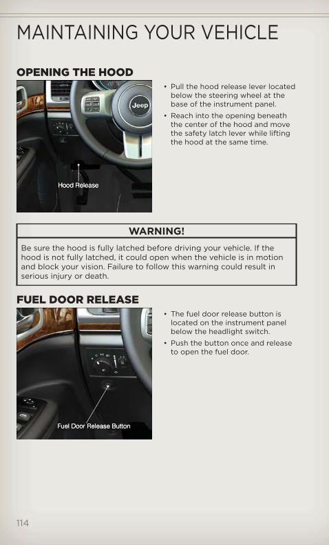
OPENING THE HOOD• Pull the hood release lever located
below the steering wheel at thebase of the instrument panel.
• Reach into the opening beneaththe center of the hood and movethe safety latch lever while liftingthe hood at the same time.
WARNING!Be sure the hood is fully latched before driving your vehicle. If thehood is not fully latched, it could open when the vehicle is in motionand block your vision. Failure to follow this warning could result inserious injury or death.
FUEL DOOR RELEASE• The fuel door release button is
located on the instrument panelbelow the headlight switch.
• Push the button once and releaseto open the fuel door.
MAINTAINING YOUR VEHICLE
114

Fuel Door Emergency Release• To manually open the fuel door,
remove the storage bin located inthe rear cargo area and pull therelease cable located in thestorage bin opening.
Storage Bin Removal• Push down on inboard edge. This will pop up outboard edge.
• Grab popped up outboard edge with other hand to disengage snaps.
• Remove storage bin.
MAINTAINING YOUR VEHICLE
115

ENG
INE
CO
MPA
RTM
ENT
3.6
LE
NG
INE
MAINTAINING YOUR VEHICLE
116

5.7L
Eng
ine
MAINTAINING YOUR VEHICLE
117
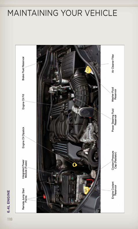
6.4
LE
NG
INE
MAINTAINING YOUR VEHICLE
118
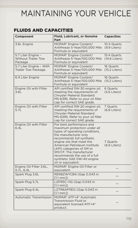
FLUIDS AND CAPACITIESComponent Fluid, Lubricant, or Genuine
PartCapacities
3.6L Engine MOPAR® Engine Coolant/Antifreeze 5-Year/100,000 MileFormula or equivalent
10.4 Quarts(9.9 Liters)
5.7 Liter Engine –Without Trailer TowPackage
MOPAR® Engine Coolant/Antifreeze 5-Year/100,000 MileFormula or equivalent
15.4 Quarts(14.6 Liters)
5.7 Liter Engine – WithTrailer Tow Package.
MOPAR® Engine Coolant/Antifreeze 5-Year/100,000 MileFormula or equivalent
16 Quarts(15.2 Liters)
6.4 Liter Engine MOPAR® Engine Coolant/Antifreeze 5-Year/100,000 MileFormula or equivalent
16 Quarts(15.2 Liters)
Engine Oil with Filter3.6L
API certified 5W-30 engine oil,meeting the requirements ofChrysler Material StandardMS-6395. Refer to your oil fillercap for correct SAE grade.
6 Quarts(5.6 Liters)
Engine Oil with Filter5.7L
API certified 5W-20 engine oil,meeting the requirements ofChrysler Material StandardMS-6395. Refer to your oil fillercap for correct SAE grade.
7 Quarts(6.6 Liters)
Engine Oil with Filter6.4L
For best performance andmaximum protection under alltypes of operating conditions,the manufacturer onlyrecommends full syntheticengine oils that meet theAmerican Petroleum Institute(API) categories of SM orSM/CF. The manufacturerrecommends the use of a fullsynthetic SAE 0W-40 engineoil or equivalent.
7 Quarts(6.6 Liters)
Engine Oil Filter 3.6L,5.7L, 6.4L
MOPAR® Engine Oil Filter orequivalent. —
Spark Plug 3.6L RER8ZWYCB4 (Gap 0.043 in[1.1 mm]) —
Spark Plug 5.7L LZFR5C–11G (Gap 0.043 in[1.1 mm]) —
Spark Plug 6.4L LZTR6AP11EG (Gap 0.043 in[1.1 mm]) —
Automatic Transmission MOPAR® ATF+4® AutomaticTransmission Fluid orequivalent licensed ATF+4®product.
—
MAINTAINING YOUR VEHICLE
119
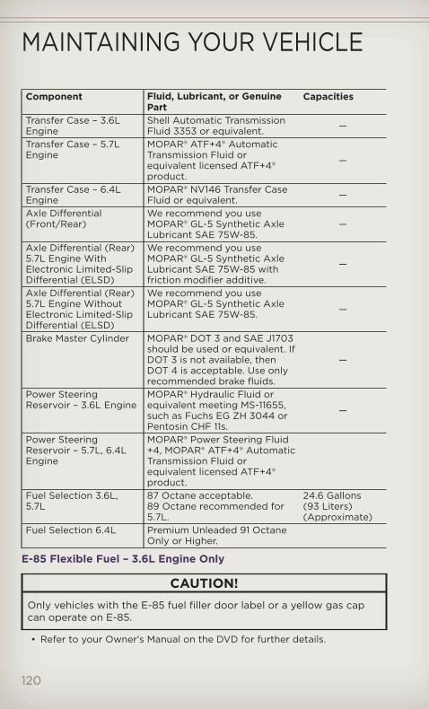
Component Fluid, Lubricant, or GenuinePart
Capacities
Transfer Case – 3.6LEngine
Shell Automatic TransmissionFluid 3353 or equivalent. —
Transfer Case – 5.7LEngine
MOPAR® ATF+4® AutomaticTransmission Fluid orequivalent licensed ATF+4®product.
—
Transfer Case – 6.4LEngine
MOPAR® NV146 Transfer CaseFluid or equivalent. —
Axle Differential(Front/Rear)
We recommend you useMOPAR® GL-5 Synthetic AxleLubricant SAE 75W-85.
—
Axle Differential (Rear)5.7L Engine WithElectronic Limited-SlipDifferential (ELSD)
We recommend you useMOPAR® GL-5 Synthetic AxleLubricant SAE 75W-85 withfriction modifier additive.
—
Axle Differential (Rear)5.7L Engine WithoutElectronic Limited-SlipDifferential (ELSD)
We recommend you useMOPAR® GL-5 Synthetic AxleLubricant SAE 75W-85. —
Brake Master Cylinder MOPAR® DOT 3 and SAE J1703should be used or equivalent. IfDOT 3 is not available, thenDOT 4 is acceptable. Use onlyrecommended brake fluids.
—
Power SteeringReservoir – 3.6L Engine
MOPAR® Hydraulic Fluid orequivalent meeting MS-11655,such as Fuchs EG ZH 3044 orPentosin CHF 11s.
—
Power SteeringReservoir – 5.7L, 6.4LEngine
MOPAR® Power Steering Fluid+4, MOPAR® ATF+4® AutomaticTransmission Fluid orequivalent licensed ATF+4®product.
Fuel Selection 3.6L,5.7L
87 Octane acceptable.89 Octane recommended for5.7L.
24.6 Gallons(93 Liters)(Approximate)
Fuel Selection 6.4L Premium Unleaded 91 OctaneOnly or Higher.
E-85 Flexible Fuel – 3.6L Engine Only
CAUTION!Only vehicles with the E-85 fuel filler door label or a yellow gas capcan operate on E-85.
• Refer to your Owner's Manual on the DVD for further details.
MAINTAINING YOUR VEHICLE
120

MA
INTE
NA
NC
EC
HA
RT
Mile
s:8,
000
16,0
0024
,000
32,0
0040
,000
48,0
0056
,000
64,0
0072
,000
80,0
0088
,000
96,0
0010
4,00
0
Or
Mo
nths
:6
1218
2430
364
24
854
60
66
7278
Or
Kilo
met
ers:
13,0
0026
,000
39,0
0052
,000
65,0
0078
,000
91,0
0010
4,00
0117
,000
130,
000
143,
000
156,
000
169,
000
Cha
nge
the
eng
ine
oil
and
eng
ine
oil
filt
er.
XX
XX
XX
XX
XX
XX
X
Ro
tate
the
tire
s,ro
tate
atth
efi
rst
sig
no
fir
-re
gul
arw
ear,
even
ifit
occ
urs
bef
ore
sche
dul
edm
aint
enan
ce.
XX
XX
XX
XX
XX
XX
X
Ifus
ing
your
vehi
cle
for
any
of
the
follo
win
g:
dus
tyo
ro
ff-r
oad
cond
itio
ns.I
nsp
ect
the
en-
gin
eai
rcl
eane
rfi
lter
;rep
lace
ifne
cess
ary.
XX
X
Insp
ect
the
bra
kelin
ing
s;re
pla
ceif
nece
ssar
y.X
XX
XX
X
Insp
ect
the
CV
join
ts.
XX
XX
Insp
ect
the
exha
ust
syst
em.
XX
XX
X
Insp
ect
the
tran
sfer
case
flui
dan
dch
ang
eif
nece
ssar
y.X
XX
Ad
just
the
par
king
bra
keo
nve
hicl
eseq
uip
ped
wit
hfo
urw
heel
dis
cb
rake
s.X
XX
Cha
nge
the
auto
mat
ictr
ansm
issi
on
flui
dan
dfi
lter
ifus
ing
your
vehi
cle
for
any
of
the
follo
w-
ing
:po
lice,
taxi
,fle
eto
rfr
eque
nttr
aile
rto
win
g.
X
Insp
ect
the
fro
ntan
dre
arax
lefl
uid
,cha
nge
ifne
cess
ary.
XX
XX
Insp
ect
fro
ntsu
spen
sio
n,ti
ero
den
ds,
and
bo
ot
seal
s,fo
rcr
acks
or
leak
san
dal
lpar
tsfo
rd
amag
e,w
ear,
imp
rop
erlo
ose
ness
or
end
pla
y;re
pla
ceif
nece
ssar
y.
XX
XX
XX
Rep
lace
the
eng
ine
air
clea
ner.
XX
X
Rep
lace
the
air
cond
itio
ning
filt
er.
XX
XX
XX
Rep
lace
the
spar
kp
lug
s(5
.7L
eng
ine)
XX
X
Rep
lace
the
spar
kp
lug
s(3
.6L
eng
ine)
X
MAINTAINING YOUR VEHICLE
121

Mile
s:8,
000
16,0
0024
,000
32,0
0040
,000
48,0
0056
,000
64,0
0072
,000
80,0
0088
,000
96,0
0010
4,00
0
Or
Mo
nths
:6
1218
2430
364
24
854
60
66
7278
Or
Kilo
met
ers:
13,0
0026
,000
39,0
0052
,000
65,0
0078
,000
91,0
0010
4,00
0117
,000
130,
000
143,
000
156,
000
169,
000
Insp
ect
and
rep
lace
PC
Vva
lve.
*X
Flu
shan
dre
pla
ceth
een
gin
eco
ola
ntat
60
mo
nths
or
104
,00
0m
iles
(16
9,0
00
km)
whi
chev
erco
mes
firs
t.X
Flu
shan
dre
pla
ceth
een
gin
eco
ola
ntat
104
,00
0m
iles
(16
9,0
00
km)
or
60
mo
nths
whi
chev
erco
mes
firs
t.X
•*
Thi
sm
aint
enan
ceis
reco
mm
end
edb
yth
em
anuf
actu
rer
toth
eo
wne
r,b
utis
not
req
uire
dto
mai
ntai
nem
issi
ons
war
rant
y.
•R
efer
toth
eO
wne
r's
Man
ualo
nth
eD
VD
for
com
ple
tem
aint
enan
cesc
hed
ule.
MAINTAINING YOUR VEHICLE
122
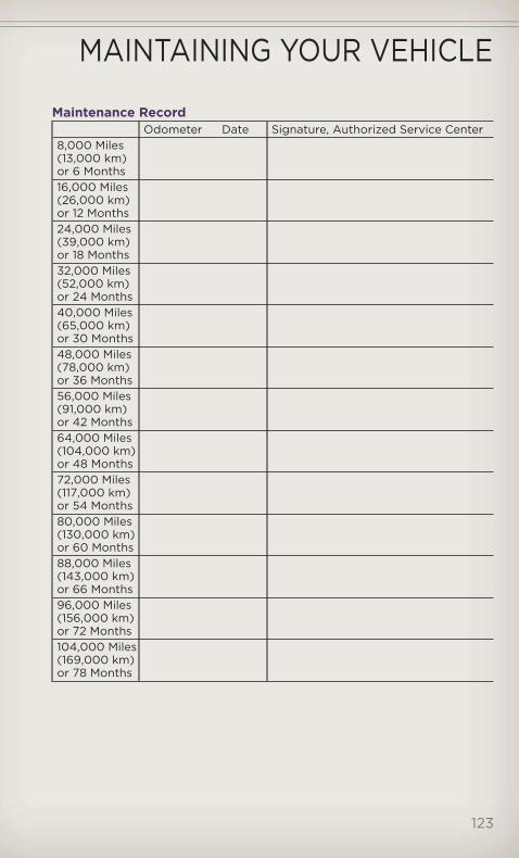
Maintenance RecordOdometer Date Signature, Authorized Service Center
8,000 Miles(13,000 km)or 6 Months16,000 Miles(26,000 km)or 12 Months24,000 Miles(39,000 km)or 18 Months32,000 Miles(52,000 km)or 24 Months40,000 Miles(65,000 km)or 30 Months48,000 Miles(78,000 km)or 36 Months56,000 Miles(91,000 km)or 42 Months64,000 Miles(104,000 km)or 48 Months72,000 Miles(117,000 km)or 54 Months80,000 Miles(130,000 km)or 60 Months88,000 Miles(143,000 km)or 66 Months96,000 Miles(156,000 km)or 72 Months104,000 Miles(169,000 km)or 78 Months
MAINTAINING YOUR VEHICLE
123
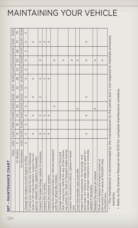
SRT
–M
AIN
TEN
AN
CE
CH
AR
TM
iles:
6,00
012
,000
18,0
0024
,000
30,0
0036
,000
42,0
0048
,000
54,0
0060
,000
66,0
0072
,000
78,0
00
Or
Mo
nths
:6
1218
2430
364
24
854
60
66
7278
Or
Kilo
met
ers:
10,0
0020
,000
30,0
0040
,000
50,0
0060
,000
70,0
0080
,000
90,0
0010
0,00
0110
,000
120,
000
130,
000
Cha
nge
the
eng
ine
oil
and
eng
ine
oil
filt
er.
XX
XX
XX
XX
XX
XX
X
Ifus
ing
your
vehi
cle
for
any
of
the
follo
win
g:
dus
tyo
ro
ff-r
oad
cond
itio
ns.I
nsp
ect
the
en-
gin
eai
rcl
eane
rfi
lter
;rep
lace
ifne
cess
ary.
XX
XX
X
Insp
ect
the
bra
kelin
ing
s;re
pla
ceif
nece
ssar
y.X
XX
XX
X
Insp
ect
the
CV
join
ts.
XX
XX
Insp
ect
the
exha
ust
syst
em.
XX
XX
Ad
just
the
par
king
bra
keo
nve
hicl
eseq
uip
ped
wit
hfo
urw
heel
dis
cb
rake
s.X
X
Cha
nge
the
auto
mat
ictr
ansm
issi
on
flui
dan
dfi
lter
ifus
ing
your
vehi
cle
for
any
of
the
follo
w-
ing
:po
lice,
taxi
,fle
eto
rfr
eque
nttr
aile
rto
win
g.
X
Insp
ect
the
acce
sso
ryb
elt(
s),r
epla
ceif
nece
s-sa
ry.
X
Dra
inth
etr
ansf
erca
sean
dre
fill.
XX
Insp
ect
fro
ntsu
spen
sio
n,ti
ero
den
ds,
and
bo
ot
seal
s,fo
rcr
acks
or
leak
san
dal
lpar
tsfo
rd
amag
e,w
ear,
imp
rop
erlo
ose
ness
or
end
pla
y;re
pla
ceif
nece
ssar
y.
XX
XX
X
Rep
lace
the
eng
ine
air
clea
ner.
XX
Flu
shan
dre
pla
ceth
een
gin
eco
ola
ntat
60
mo
nths
ifno
td
one
at10
2,0
00
mile
s(1
70,0
00
km).
X
•*
Thi
sm
aint
enan
ceis
reco
mm
end
edb
yth
em
anuf
actu
rer
toth
eo
wne
r,b
utis
not
req
uire
dto
mai
ntai
nem
issi
ons
war
rant
y.
•R
efer
toth
eO
wne
r's
Man
ualo
nth
eD
VD
for
com
ple
tem
aint
enan
cesc
hed
ule.
MAINTAINING YOUR VEHICLE
124

SRT – Maintenance RecordOdometer Date Signature, Authorized Service
Center6,000 Miles(10,000 km)or 6 Months12,000 Miles(20,000 km)or 12 Months18,000 Miles(30,000 km)or 18 Months24,000 Miles(40,000 km)or 24 Months30,000 Miles(50,000 km)or 30 Months36,000 Miles(60,000 km)or 36 Months42,000 Miles(70,000 km)or 42 Months48,000 Miles(80,000 km)or 48 Months54,000 Miles(90,000 km)or 54 Months60,000 Miles(100,000 km)or 60 Months66,000 Miles(110,000 km)or 66 Months72,000 Miles(120,000 km)or 72 Months78,000 Miles(130,000 km)or 78 Months
MAINTAINING YOUR VEHICLE
125

FUSES
MAINTAINING YOUR VEHICLE
126

Integrated Power Module (fuses)The integrated power module is located on the right side of the enginecompartment. This center contains cartridge fuses and mini fuses. Adescription of each fuse and component may be stamped on the insidecover, otherwise the cavity number of each fuse is stamped on the insidecover that corresponds to the following chart.
Cavity CartridgeFuse
Mini Fuse Description
J01 40 AmpGreen
Air Suspension
J02 30 Amp Pink Power Liftgate ModuleJ03 30 Amp Pink Trailer TowJ04 25 Amp
NaturalDriver Door Node
J05 25 AmpNatural
Passenger Door Node
J06 40 AmpGreen
ABS Pump Feed/ESP
J07 30 Amp Pink ABS Valve Feed/ESPJ08 40 Amp
GreenPower Seat
J09 30 Amp Pink E-BrakeJ10 30 Amp Pink Headlamp Wash Relay ContactJ11 30 Amp Pink DTCMJ13 60 Amp
YellowStreaming Video Module/VES3 Module/VES2Module/DISP/DVD
J14 20 Amp Blue Trailer Tow Lamps/Park LampsJ15 40 Amp
GreenRear Window Defroster
J17 40 AmpGreen
Starter Motor Solenoid Feed
J18 20 Amp Blue NGC/PCM Transmission RangeJ19 60 Amp
YellowRad Fan Motor HI/Rad FanMotor Low
J20 30 Amp Pink Front Wiper GroundJ21 20 Amp Blue Front Washer Control/Rear
Washer ControlJ22 25 Amp
NaturalPWR Batt – Sunroof Mod
M1 15 Amp Blue Sw Stop Switch Lamp FeedM2 20 Amp
YellowELSD/Air Suspension
M3 20 AmpYellow
Liftgate Unlock/DRL Relay
M4 10 Amp Red Trailer Tow
MAINTAINING YOUR VEHICLE
127
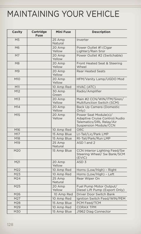
Cavity CartridgeFuse
Mini Fuse Description
M5 25 AmpNatural
Inverter
M6 20 AmpYellow
Power Outlet #1 (CigarLighter)/Rain Snsr
M7 20 AmpYellow
Power Outlet #2 (Switchable)
M8 20 AmpYellow
Front Heated Seat & SteeringWheel
M9 20 AmpYellow
Rear Heated Seats
M10 20 AmpYellow
HFM/Vanity Lamp/UGDO Mod
M11 10 Amp Red HVAC (ATC)M12 30 Amp
GreenRadio/Amplifier
M13 20 AmpYellow
Main #2 CCN/WIN/ITM/Siren/Multifunction Switch (SCM)
M14 20 AmpYellow
Back Up Camera (DomesticOnly)
M15 20 AmpYellow
Power Seat Module(s)/Adaptive Cruise Control/AudioTelematics/DRL Relay/AirSuspension Module/CCN
M16 10 Amp Red ORCM17 15 Amp Blue Lt-Tail/Lic/Park LMPM18 15 Amp Blue Rt-Tail/Park/Run LMPM19 25 Amp
NaturalASD 1 and 2
M20 15 Amp Blue CCN Interior Lighting Feed/SwSteering Wheel/ Sw Bank/SCM(EVIC)
M21 20 AmpYellow
ASD 3
M22 10 Amp Red Horns (Low/High) – RightM23 10 Amp Red Horns (Low/High) – LeftM24 25 Amp
NaturalRear Wiper On
M25 20 AmpYellow
Fuel Pump Motor Output/Diesel Lift Pump (Export Only)
M26 10 Amp Red Driver Door Switch BankM27 10 Amp Red Ignition Switch Feed/WIN/PEMM28 15 Amp Blue PCM Feed/TCMM29 10 Amp Red CORAX TPMM30 15 Amp Blue J1962 Diag Connector
MAINTAINING YOUR VEHICLE
128

Cavity CartridgeFuse
Mini Fuse Description
M31 20 AmpYellow
B/U Lamps
M32 10 Amp Red ORC FeedM33 10 Amp Red NGC (PCM)/TCMM34 10 Amp Red Park Assist Module/HVAC
Module/IR Sensor/CompassModule
M35 15 Amp Blue LH Rear ParklampsM36 20 Amp
YellowPower Outlet
M37 10 Amp Red ABS/ESP Module/StoplampSwitch Sensor
M38 25 AmpNatural
All Door Lock & Unlock
CAUTION!• When installing the integrated power module cover, it is important
to ensure the cover is properly positioned and fully latched. Failureto do so may allow water to get into the integrated power moduleand possibly result in a electrical system failure.
• When replacing a blown fuse, it is important to use only a fusehaving the correct amperage rating. The use of a fuse with a ratingother than indicated may result in a dangerous electrical systemoverload. If a properly rated fuse continues to blow, it indicates aproblem in the circuit that must be corrected.
TIRE PRESSURES• Check the inflation pressure of each tire, including the spare tire, at least
monthly and inflate to the recommended pressure for your vehicle.
• The tire pressures recommended for your vehicle are found on the “Tireand Loading Information” label located on the driver’s side dooropening.
NOTE: Refer to the Owner's Manualon the DVD for more informationregarding tire warnings andinstructions.
MAINTAINING YOUR VEHICLE
129

WARNING!• Overloading of your tires is dangerous. Overloading can cause tire
failure, affect vehicle handling, and increase your stopping distance.Use tires of the recommended load capacity for your vehicle. Neveroverload them.
• Improperly inflated tires are dangerous and can cause collisions.Under-inflation is the leading cause of tire failure and may result insevere cracking, component separation, or “blow out”. Over-inflation reduces a tire’s ability to cushion shock. Objects on theroad and chuck holes can cause damage that results in tire failure.Unequal tire pressures can cause steering problems. You could losecontrol of your vehicle. Over-inflated or under-inflated tires canaffect vehicle handling and can fail suddenly, resulting in loss ofvehicle control.
WHEEL AND WHEEL TRIM CARE• All wheels and wheel trim, especially aluminum and chrome plated
wheels, should be cleaned regularly with a mild soap and water toprevent corrosion.
• To remove heavy soil and/or excessive brake dust, use MOPAR® WheelCleaner or equivalent or select a non-abrasive, non-acidic cleaner.
CAUTION!Do not use scouring pads, steel wool, a bristle brush, or metalpolishes. Do not use oven cleaner. These products may damage thewheel's protective finish. Avoid automatic car washes that use acidicsolutions or harsh brushes that may damage the wheel's protectivefinish. Only MOPAR® Wheel Cleaner or equivalent is recommended.
MAINTAINING YOUR VEHICLE
130

EXTERIOR BULBSLIGHT BULBS – Exterior Bulb NumberTail, Stop, Turn Lamp 3057Liftgate Backup Lamps 921 (W16W)Center High-Mounted Stop Lamp(CHMSL)
LED (*)
Fog Lamp – If Equipped PSX24WFront Park/Turn Signal 7444NAFront Side Marker, License Lamp W5WHeadlamp – High Intensity Discharge(HID)
D1S – Serviced at Authorized Dealer(**)
Headlamp – Low Beam H11Headlamp – High Beam 9005
* CHMSL is not serviceable. It is a LED lamp. To replace the LED, the entireCHMSL assembly must be replaced.
** The headlamps are a type of high-voltage discharge tube. High voltagecan remain in the circuit even with the headlamp switch off and the Key Fobremoved. Because of this, you should not attempt to service a headlampbulb yourself. If a headlamp bulb fails, take your vehicle to an authorizeddealer for service.
MAINTAINING YOUR VEHICLE
131

CHRYSLER GROUP LLC CUSTOMER CENTERP.O. Box 21–8004
Auburn Hills, MI 48321–8004
Phone: 1–877–426–5337
CHRYSLER CANADA INC. CUSTOMER CENTERP.O. Box 1621
Windsor, Ontario N9A 4H6
Phone: 1–800–465–2001 (English)
Phone: 1–800–387–9983 (French)
ASSISTANCE FOR THE HEARING IMPAIRED• To assist customers who have hearing difficulties, the manufacturer has
installed special TDD (Telecommunication Devices for the Deaf)equipment at its customer center. Any hearing or speech impairedcustomer, who has access to a TDD or a conventional teletypewriter(TTY) in the United States, can communicate with the manufacturer bydialing 1–800–380–CHRY. Canadian residents with hearing difficultiesthat require assistance can use the special needs relay service offered byBell Canada. For TTY teletypewriter users, dial 711 and for Voice callers,dial 1–800–855–0511 to connect with a Bell Relay Service operator.
WARNING!Engine exhaust, some of its constituents, and certain vehiclecomponents contain, or emit, chemicals known to the State ofCalifornia to cause cancer and birth defects, or other reproductiveharm. In addition, certain fluids contained in vehicles and certainproducts of component wear contain, or emit, chemicals known to theState of California to cause cancer and birth defects, or otherreproductive harm.
PUBLICATIONS ORDERING• If you are the first registered retail owner of your vehicle, you may
obtain one free printed copy of the Owner's Manual, Warranty Booklet orRadio Manuals on your DVD by calling 1–877–426–5337 (U.S.) or1–800–387–1143 (Canada) or by contacting your dealer.
• Replacement User Guide kits or DVDs or, if you prefer, additional printedcopies of the Owner's Manual, Warranty Booklet or Radio Manuals maybe purchased by visiting www.techauthority.com or by calling1–800–890–4038 (U.S.) or 1–800–387–1143 (Canada). Visa, Master Card,American Express and Discover orders are accepted. If you prefermailing your order, please call the above numbers for an order form.
CONSUMER ASSISTANCE
132

NOTE: A street address is required when ordering manuals (no P.O. Boxes).
NOTE:• The Owner's Manual and User Guide electronic files are also available on
the Chrysler, Jeep, Ram Truck and Dodge websites.• Click on the "For Owners" tab, select "Owner/Service Manuals", then select
your desired model year and vehicle from the drop-down lists.
REPORTING SAFETY DEFECTS IN THE 50 UNITEDSTATES AND WASHINGTON, D.C.
• If you believe that your vehicle has a defect that could cause a collisionor cause injury or death, you should immediately inform the NationalHighway Traffic Safety Administration (NHTSA) in addition to notifyingthe manufacturer.
• If NHTSA receives similar complaints, it may open an investigation, and ifit finds that a safety defect exists in a group of vehicles, it may order arecall and remedy campaign. However, NHTSA cannot become involvedin individual problems between you, your authorized dealer, and themanufacturer.
• To contact NHTSA, you may either call the Auto Safety Hotline toll freeat 1–888–327–4236 (TTY: 1–800–424– 9153), or go to http://www.safercar.gov; or write to: Administrator, NHTSA, 1200 New JerseyAvenue, SE., West Building, Washington, D.C. 20590. You can also obtainother information about motor vehicle safety fromhttp://www.safercar.gov.
In Canada• If you believe that your vehicle has a safety defect, you should contact
the Customer Service Department immediately. Canadian customers whowish to report a safety defect to the Canadian government shouldcontact Transport Canada, Motor Vehicle Defect Investigations andRecalls at 1-800-333-0510 or go to http://www.tc.gc.ca/roadsafety/
• French Canadian customers who wish to report a safety defect to theCanadian government should contact Transport Canada, Motor VehicleDefect Investigations and Recalls at 1-800-333-0510 or go tohttp://www.tc.gc.ca/securiteroutiere/
CONSUMER ASSISTANCE
133
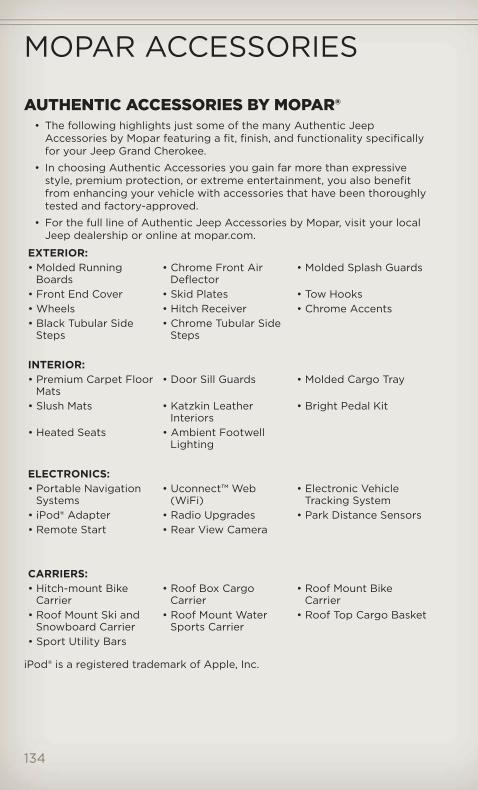
AUTHENTIC ACCESSORIES BY MOPAR®• The following highlights just some of the many Authentic Jeep
Accessories by Mopar featuring a fit, finish, and functionality specificallyfor your Jeep Grand Cherokee.
• In choosing Authentic Accessories you gain far more than expressivestyle, premium protection, or extreme entertainment, you also benefitfrom enhancing your vehicle with accessories that have been thoroughlytested and factory-approved.
• For the full line of Authentic Jeep Accessories by Mopar, visit your localJeep dealership or online at mopar.com.
EXTERIOR:• Molded Running
Boards• Chrome Front Air
Deflector• Molded Splash Guards
• Front End Cover • Skid Plates • Tow Hooks• Wheels • Hitch Receiver • Chrome Accents• Black Tubular Side
Steps• Chrome Tubular Side
Steps
INTERIOR:• Premium Carpet Floor
Mats• Door Sill Guards • Molded Cargo Tray
• Slush Mats • Katzkin LeatherInteriors
• Bright Pedal Kit
• Heated Seats • Ambient FootwellLighting
ELECTRONICS:• Portable Navigation
Systems• Uconnect™ Web
(WiFi)• Electronic Vehicle
Tracking System• iPod® Adapter • Radio Upgrades • Park Distance Sensors• Remote Start • Rear View Camera
CARRIERS:• Hitch-mount Bike
Carrier• Roof Box Cargo
Carrier• Roof Mount Bike
Carrier• Roof Mount Ski and
Snowboard Carrier• Roof Mount Water
Sports Carrier• Roof Top Cargo Basket
• Sport Utility Bars
iPod® is a registered trademark of Apple, Inc.
MOPAR ACCESSORIES
134

Adaptive Cruise Control (ACC)(Cruise Control) . . . . . . . . . . . 31Air Conditioning . . . . . . . . . 35,36Air Suspension . . . . . . . . . . . . 86Airbag . . . . . . . . . . . . . . . . . . 17Airbag Light . . . . . . . . . . . . . 100Alarm, Panic . . . . . . . . . . . . . . 10Anti-Lock Brake System(ABS) . . . . . . . . . . . . . . . . . . 99Arming Theft System (SecurityAlarm) . . . . . . . . . . . . . . . . . 16Audio Settings . . 44,45,46,48,51,60Automatic Dimming Mirror . . . . 30Automatic Headlights . . . . . . . 28Automatic Temperature Control(ATC) . . . . . . . . . . . . . . . . . . 35Automatic Transmission
Autostick . . . . . . . . . . . . . . 93Fluid Type . . . . . . . . . . . . . 119
Autostick . . . . . . . . . . . . . . . 93Auxiliary Audio/VideoInput Jacks . . . . . . . . . . . . . . 77Axle Fluid . . . . . . . . . . . . 119,120Axle Lubrication (Axle Fluid) . . 120
Back-Up Camera . . . . . . . . . . . 36Battery
Charging System Light . . . . . 99Belts, Seat . . . . . . . . . . . . . . . 16Blind Spot Monitoring . . . . . . . 37Brake Fluid . . . . . . . . . . . . 119,120Brake System
Warning Light . . . . . . . . . . . 98Break-In Recommendations,New Vehicle . . . . . . . . . . . . . . 27Bulb Replacement . . . . . . . . . . 131Button, Start/Stop Removal . . 10,14
Calibration, Compass . . . . . . . . 78Change Oil Indicator . . . . . . . 100Changing A Flat Tire . . . . . . . . 102Charging System Light . . . . . . . 99Check Engine Light (MalfunctionIndicator Light) . . . . . . . . . . . 99Child Restraint . . . . . . . . . . . . 18Child Restraint Tether Anchors . . 18Climate Control . . . . . . . . . . . 35Clock Setting . . . . . . . 44,46,49,57
Command View Skylights . . . . . 39Compass Calibration . . . . . . . . 78Cooling System
Coolant Capacity . . . . . . . . . 119Cruise Control (SpeedControl) . . . . . . . . . . . . . . . . 30Cruise Light . . . . . . . . . . . . . . 30Customer Assistance . . . . . . . 132
Defects, Reporting . . . . . . . . . 133Defroster, Rear Window . . . . . . 35Defroster, Windshield . . . . . . . . 35Dimmer Control . . . . . . . . . . . 28Dimmer Switch, Headlight . . . . . 28Disarming, Theft System . . . . . . 16
E-85 Fuel . . . . . . . . . . . . . . . 120ECO . . . . . . . . . . . . . . . . . . . 78Electronic Range Select (ERS) . . 34Electronic Speed Control (CruiseControl) . . . . . . . . . . . . . . . . 30Electronic Stability Control(ESC) . . . . . . . . . . . . . . . . . . 99Electronic Throttle Control WarningLight . . . . . . . . . . . . . . . . . . 100Electronic Vehicle InformationCenter (EVIC) . . . . . . . . . 78,79,95Electronics
Your Vehicle's Sound System . 42Emergency Key . . . . . . . . . . . . 10Emergency, In Case of
Jacking . . . . . . . . . . . . . . . 102Overheating . . . . . . . . . . . . 101
EngineBreak-In Recommendations . . 27Compartment . . . . . . . . . . . 116Coolant (Antifreeze) . . . . . . . 119Malfunction Indicator (CheckEngine) . . . . . . . . . . . . . . . 99Oil . . . . . . . . . . . . . . . . . . 119Oil Filter . . . . . . . . . . . . . . . 119Oil Selection . . . . . . . . . . . . 119Overheating . . . . . . . . . . . . 101Starting . . . . . . . . . . . . . . . 15Stopping . . . . . . . . . . . . . . . 15
Event Data Recorder . . . . . . . . 113Exterior Lights . . . . . . . . . . . . 131
INDEX
135
Flexible Fuel Vehicles . . . . . . . 120Flipper Glass, Liftgate . . . . . . . 37Fluid Capacities . . . . . . . . . . . 119Fluids . . . . . . . . . . . . . . . . . . 119Fog Lights . . . . . . . . . . . . . . . 28Folding Front Passenger Seat . . 22Folding Rear Seat . . . . . . . . . . 23Four Wheel Drive . . . . . . . . . . 84
Shifting . . . . . . . . . . . . . . . 85Four Wheel Drive Operation . . . 84
Shifting into Transfer CaseNeutral (N) . . . . . . . . . . . . . 85Shifting out of Transfer CaseNeutral (N) . . . . . . . . . . . . . 85
Front Heated Seats . . . . . . . . . 24Fuel
Filler Cap (Gas Cap) . . . . . . 100Filler Door (Gas Cap) . . . . . . 114Filler Door EmergencyRelease . . . . . . . . . . . . . . . 115Specifications . . . . . . . . 119,120
Fuses . . . . . . . . . . . . . . . . . 126
Garage Door Opener(HomeLink®) . . . . . . . . . . . . . 79Gas Cap (Fuel Filler Cap) . . . . 100
Headlights . . . . . . . . . . . . . . . 28Automatic . . . . . . . . . . . . . . 28Dimmer Switch . . . . . . . . . . 28High Beam . . . . . . . . . . . . . 30High Beam/Low Beam SelectSwitch . . . . . . . . . . . . . . . . 30
Heated Mirrors . . . . . . . . . . 35,36Heated Seats . . . . . . . . . . . . . 24Heated Steering Wheel . . . . . . 25High Beam/Low Beam Select(Dimmer) Switch . . . . . . . . . . 30Hill Descent Control . . . . . . . . . 88Hill Start Assist . . . . . . . . . . . . 88HomeLink® (Garage DoorOpener) Transmitter . . . . . . . . 79Hood Release . . . . . . . . . . . . 114
Instrument Cluster . . . . . . . . . . 8Indicators . . . . . . . . . . . . . . . 9
Instrument Cluster WarningLights . . . . . . . . . . . . . . . . 8,97Integrated Power Module(Fuses) . . . . . . . . . . . . . . . . 127Intermittent Wipers(Delay Wipers) . . . . . . . . . . . . 29Introduction . . . . . . . . . . . . . . 3Inverter Outlet (115V) . . . . . . . . 82Inverter, Power . . . . . . . . . . . . 82
iPod®/USB/MP3 Control . . . . . . 70Bluetooth Streaming Audio . . 76
Jack Location . . . . . . . . . . . . 103Jack Operation . . . . . . . . 102,104Jacking Instructions . . . . . . . . 104Jump Starting . . . . . . . . . . . . 108
Key Fob . . . . . . . . . . . . . . . . . 10Keyless Enter-N-Go™ . . . . . . . . 13
Lock/Unlock . . . . . . . . . . . . 13Starting/Stopping . . . . . . . . . 15
Lane Change Assist . . . . . . . . . 29LATCH (Lower Anchors andTether for CHildren) . . . . . . . . . 18Liftgate . . . . . . . . . . . . . . . . . 37Liftgate Flipper Glass . . . . . . . . 37Liftgate, Power . . . . . . . . . . 10,37Light Bulbs . . . . . . . . . . . . . . 131Lights
Warning (Instrument ClusterDescription) . . . . . . . . . . . . . 8
Maintenance Record . . . . . 123,125Maintenance Schedule . . . . 121,124Malfunction Indicator Light(Check Engine) . . . . . . . . . . . 99Media Center Radio . . . . . . . 44,46Memory Seat . . . . . . . . . . . . . 21Mirrors
Automatic Dimming . . . . . . . 30Heated . . . . . . . . . . . . . . 35,36
MOPAR® Accessories . . . . . . . 134
Navigation . . . . . . . . . . . . . 54,63New Vehicle Break-In Period . . . 27
INDEX
136

Oil Change Indicator . . . . . . . 100Oil Change Indicator, Reset . . . 100Oil Pressure Light . . . . . . . . . . 99Oil, Engine
Capacity . . . . . . . . . . . . . . 119Outlet
Power . . . . . . . . . . . . . . . . 82Overheating, Engine . . . . . . . . 101
Panic Alarm . . . . . . . . . . . . . . 10Park Sense System, Rear . . . . . 36Phone (Pairing) . . . . . . . . . . . 72Phone (Uconnect) . . . . . . . . . . 71Placard, Tire and LoadingInformation . . . . . . . . . . . . . . 129Power
Glass Sunroof . . . . . . . . . . . 38Inverter . . . . . . . . . . . . . . . 82Lift Gate . . . . . . . . . . . . . . . 10Outlet (Auxiliary ElectricalOutlet) . . . . . . . . . . . . . . . . 82Seats . . . . . . . . . . . . . . . . . 20Steering . . . . . . . . . . . . 119,120Tilt/Telescoping SteeringColumn . . . . . . . . . . . . . . . 26
Preparation for Jacking . . . . . . 104Programmable ElectronicFeatures . . . . . . . . . . . . . . 79,95
Quadra-Lift . . . . . . . . . . . . . . 86Quadra-Trac . . . . . . . . . . . . . 84
Radio Operation . . . . . . . . . 48,57Rain Sensitive Wiper System . . . 29Rear Camera . . . . . . . . . . . . . 36Rear Cross Path . . . . . . . . . . . 37Rear Heated Seats . . . . . . . . . 24Rear Park Sense System . . . . . . 36Rear Seat, Folding . . . . . . . . . . 23Recreational Towing . . . . . . . . 90
Shifting into Transfer CaseNeutral (N) . . . . . . . . . . . . . 90
Remote Starting System . . . . . . 12Removal, Start/Stop Button . . 10,14Replacement Bulbs . . . . . . . . . 131Reporting Safety Defects . . . . . 133Restraints, Child . . . . . . . . . . . 18
Roll Over Warning . . . . . . . . . . 4
Seat Belts . . . . . . . . . . . . . . . 16Seats . . . . . . . . . . . . . . . . . . 20
Adjustment . . . . . . . . . . . . . 22Folding Front Passenger . . . . 22Heated . . . . . . . . . . . . . . . . 24Lumbar Support . . . . . . . . . . 21Memory . . . . . . . . . . . . . . . 21Power . . . . . . . . . . . . . . . . 20Rear Folding . . . . . . . . . . . . 23Ventilated . . . . . . . . . . . . . . 24
Seek Button . . . . . . . . . . . . 45,47Selec-Terrain . . . . . . . . . . . . . 86Setting the Clock . . . . 44,46,49,57Shift Lever Override . . . . . . . . . 111Short Message Service (SMS) . . 75Signals, Turn . . . . . . . . . . . . . 29SIRIUS Travel Link . . . . . . . . . . 69SmartBeams . . . . . . . . . . . . . 28Spare Tire . . . . . . . . . . . . . . 103Spark Plugs . . . . . . . . . . . . . . 119Speed Control
Accel/Decel . . . . . . . . . . . . 30Cancel . . . . . . . . . . . . . . . . 30Distance Setting (ACC Only) . . 31Mode Setting (ACC Only) . . . . 31Resume . . . . . . . . . . . . . . . 32
Speed Control (CruiseControl) . . . . . . . . . . . . . . . . 30Start/Stop Button Removal . . 10,14Starting
Remote . . . . . . . . . . . . . . . . 12Steering
Tilt Column . . . . . . . . . . . . . 26Wheel, Heated . . . . . . . . . . . 25
Steering Wheel AudioControls . . . . . . . . . . . . . . . . 70Store Radio Presets . . . . . . . 45,47Sun Roof . . . . . . . . . . . . . . . . 38Supplemental Restraint System -Airbag . . . . . . . . . . . . . . . . . . 17
Temperature Control,Automatic (ATC) . . . . . . . . . . . 35Temperature Gauge, EngineCoolant . . . . . . . . . . . . . . . . 101Text Messaging . . . . . . . . . . . . 75
INDEX
137

Theft Alarm (Security Alarm) . . . 16Theft System Arming . . . . . . . . 16Theft System Disarming . . . . . . 16Tilt Steering Column . . . . . . . . 26Tires
Air Pressure . . . . . . . . . . . . 129Changing . . . . . . . . . . . . . 102Jacking . . . . . . . . . . . . . . . 102Pressure Warning Light . . . . . 97Spare Tire . . . . . . . . . . . . . 103
Tow Hooks, Emergency . . . . . . . 111Tow/Haul . . . . . . . . . . . . . . . 90Towing . . . . . . . . . . . . . . . . . 89
24-Hour Towing Assistance . . 97Disabled Vehicle . . . . . . . . . 112Recreational . . . . . . . . . . . . 90
Towing Vehicle Behind aMotorhome . . . . . . . . . . . . . . 90Trailer Towing
Trailer and Tongue Weight . . . 89Trailer Weight . . . . . . . . . . . . 89Transfer Case
Fluid . . . . . . . . . . . . . . 119,120Transmission
Fluid . . . . . . . . . . . . . . . . . 119
Turn Signals . . . . . . . . . . . . . . 29
Uconnect™ Phone . . . . . . . . . . 71Uconnect™ Voice Command . . . 74
Ventilated Seats . . . . . . . . . . . 24Video Entertainment System™(Rear Seat Video System) . . . . . 76Voice Commands . . . . . . . . . . 74
Warning Lights . . . . . . . . . . . . 97Warning, Roll Over . . . . . . . . . . 4Washer
Rear . . . . . . . . . . . . . . . . . 30Washers, Windshield . . . . . . . . 29Wheel and Wheel Trim Care . . . 130Wind Buffeting . . . . . . . . . . . . 41Windshield Washers . . . . . . . . 29Windshield Wipers . . . . . . . . . 29Wiper, Rear . . . . . . . . . . . . . . 30Wipers, Intermittent . . . . . . . . 29Wipers, Rain Sensitive . . . . . . . 29
INDEX
138

FREQUENTLY ASKED QUESTIONSGETTING STARTED
• How do I install my LATCH Equipped Child Seat? pg. 18
• How do I program my Front Seat Memory? pg. 21
OPERATING YOUR VEHICLE• How does the Electronic Range Select (ERS) operate? pg. 34
ELECTRONICS• Which radio is in my vehicle? pg. 44, 46, 48, 57
• How do I activate the Audio Jack? pg. 45, 48, 51, 60
• How do I set the clock on my radio? pg. 44, 46, 49, 57
• How do I use the Navigation feature? pg. 54, 63
• How do I pair my cell phone via Bluetooth® with the UConnect™Hands-Free Voice Activation System? pg. 71
• How do I use my iPod®? pg. 70
• How do I use my USB port to listen to audio through my touch-screenradio? pg. 70
• What does the ECO message mean on the EVIC display? pg. 78
• How do I configure my Universal Garage Door Opener (HomeLink)?pg. 79
OFF-ROAD CAPABILITIES• How do I shift into different four-wheel drive selections? pg. 84
UTILITY• How do I know how much I can tow with my Jeep Grand Cherokee?
pg. 89
SRT8• How do I operate the paddle shifters? pg. 93
WHAT TO DO IN EMERGENCIES• What do I do if my TPMS warning light is blinking? pg. 97
• How do I change a flat tire? pg. 102
• How do I Jump-Start my vehicle? pg. 108
MAINTAINING YOUR VEHICLE• Where is my Fuse Block located? pg. 126
• What type of oil do I use? pg. 119
• How often should I change my engine’s oil? pg. 121
• What should my tire pressure be set at? pg. 129
FAQ (How To?)
139

NOTES
140

NOTES
141

NOTES
142

NOTES
143

NOTES
144
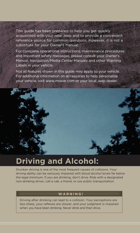
Important:This User Guide is intended to familiarize you with the important features of your vehicle. The DVD enclosed contains your Owner’s Manual, Navigation/Media Center Manuals, Warranty Booklets, Tire Warranty and 24-Hour Towing Assistance (new vehicles purchased in the U.S.) or Roadside Assistance (new vehicles purchased in Canada) in electronic format. We hope you find it useful. Replacement DVD kits may be purchased by visiting www.techauthority.com. Jeep® is a registered trademark of Chrysler Group LLC. © 2012 Chrysler Group LLC.
If you are the first registered retail owner of your
vehicle, you may obtain a complimentary printed
copy of the Owner’s Manual, Navigation/Media
Center Manuals or Warranty Booklet by calling
1-877-426-5337 (U.S.) or 1-800-387-1143 (Canada)
or by contacting your dealer.
The driver’s primary responsibility is the safe operation of the vehicle. Driving while distracted can result in loss of vehicle control, resulting in a collision and personal injury. Chrysler Group LLC strongly recommends that the driver use extreme caution when using any device or feature that may take their attention off the road. Use of any electrical devices such as cell phones, computers, portable radios, vehicle navigation or other devices by the driver while the
vehicle is moving is dangerous and could lead to a serious collision. Texting while driving is also dangerous and should never be done while the vehicle is moving. If you find yourself unable to devote your full attention to vehicle operation, pull off the road to a safe location and stop your vehicle. Some States or Provinces prohibit the use of cellular telephones or texting while driving. It is always the driver’s responsibility to comply with all local laws.
W A R N I N G !
Driving after drinking can lead to a collision. Your perceptions are less sharp, your reflexes are slower, and your judgment is impaired when you have been drinking. Never drink and then drive.
Driving and Alcohol:Drunken driving is one of the most frequent causes of collisions. Your driving ability can be seriously impaired with blood alcohol levels far below the legal minimum. If you are drinking, don’t drive. Ride with a designated non-drinking driver, call a cab, a friend, or use public transportation.
This guide has been prepared to help you get quickly acquainted with your new Jeep and to provide a convenient reference source for common questions. However, it is not a substitute for your Owner’s Manual.
For complete operational instructions, maintenance procedures and important safety messages, please consult your Owner’s Manual, Navigation/Media Center Manuals and other Warning Labels in your vehicle.
Not all features shown in this guide may apply to your vehicle. For additional information on accessories to help personalize your vehicle, visit www.mopar.com or your local Jeep dealer.
Jeep.com
12WK741-926-AA
Grand Cherokee
Fifth Edition
User Guide
Download a FREE electronic copy of the Owner’s Manual or Warranty
Booklet by visiting the For Owners tab at:
www.Jeep.com (U.S.) or
www.Jeep.ca (Canada).
Get the free mobile app for your phone
http://gettag.mobi
Download a free Vehicle Information App by visiting your application store, Keyword (Jeep), or scanning the Microsoft Tag. To put Microsoft Tags to work for you, use your mobile phone’s browser or App store to download a Microsoft Tag reader, like the free one at www.gettag.mobi. Then follow the directions to scan the code.
Includes SRT8
2012 Grand Cherokee
User Guide