
2012 Energy Codes: Performance Standards for Air Sealing ...
30
5/16/2016 1 2012 Energy Codes: Performance Standards for Air Sealing and Duct Leakage Presented by: Peter Harding Home Energy Technologies • Energy Codes – 2009, 2012 & 2015 IECC codes – Mandatory requirements – Prescriptive compliance options – Performance compliance options • Ventilation Requirements • Envelope Sealing Requirements • Duct Sealing Requirements Outline
Transcript of 2012 Energy Codes: Performance Standards for Air Sealing ...

5/16/2016
1
2012 Energy Codes: Performance Standards for Air Sealing and Duct Leakage
Presented by:Peter Harding
Home Energy Technologies
• Energy Codes – 2009, 2012 & 2015 IECC codes
– Mandatory requirements
– Prescriptive compliance options
– Performance compliance options
• Ventilation Requirements
• Envelope Sealing Requirements
• Duct Sealing Requirements
Outline

5/16/2016
2
Compliance Options for 2009 & 2012 IECC/IRC
Mandatory Provisions
• Labeling• Air sealing• Duct leakage• Programmable
thermostats• Building cavities• Equipment sizing• Lighting• Ventilation (2012)• Pipe insulation (2012)
Prescriptive Path Option
Prescriptive Envelope SpecsOr
Total UA Alternative (REScheck)Plus
Specific Insulation, Fenestration and Lighting
Provisions
Performance Path Option
Simulated Cost Performance Alternative
Compliance Options for 2015 IECC
Energy Rating Index Alternative(ERI ≤ 55 in CZ5, ≤ 54 in CZ6)
5/16/2016
3
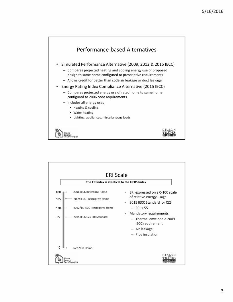
• Simulated Performance Alternative (2009, 2012 & 2015 IECC)– Compares projected heating and cooling energy use of proposed
design to same home configured to prescriptive requirements
– Allows credit for better than code air leakage or duct leakage
• Energy Rating Index Compliance Alternative (2015 IECC)– Compares projected energy use of rated home to same home
configured to 2006 code requirements
– Includes all energy uses
• Heating & cooling
• Water heating
• Lighting, appliances, miscellaneous loads
Performance-based Alternatives
• ERI expressed on a 0-100 scale of relative energy usage
• 2015 IECC Standard for CZ5
– ERI ≤ 55
• Mandatory requirements
– Thermal envelope ≥ 2009 IECC requirement
– Air leakage
– Pipe insulation
ERI Scale
100
0
2006 IECC Reference Home
2009 IECC Prescriptive Home
2012/15 IECC Prescriptive Home
2015 IECC CZ5 ERI Standard
~85
~70
55
Net Zero Home
The ER Index is identical to the HERS Index

5/16/2016
4
• 2009 IECC requires
– A permanent certificate posted on or in the electrical distribution panel
– Completed by the builder or registered design professional
– List predominant R-values, fenestration U and SHGC values, and types and efficiencies of heating, cooling and water heating equipment
• 2012 IECC additional requirements
– Air leakage test results
– Duct leakage test results
Labeling - Mandatory
Prescriptive Insulation for CZ5
Component 2009 IECC 2012/2015 IECC
Fenestration U-factor 0.35 0.32
Ceiling 38 49
Framed wall 20 or 13+5 20 or 13+5
Basement/crawl wall 10/13 15/19
Frame floor 30 30
Slab R & depth 10, 2’ 10, 2’

5/16/2016
5
• REScheck allows builders to trade-off envelope insulation values– e.g. better windows for lower R-
values in other assemblies
• Only applies to insulation requirements– No mechanical equipment trade-
offs
Prescriptive Total UA Alternative
HVAC - Mandatory2009 IECC 2012/2015 IECC
Load & sizing calculations
Manuals J & S (by reference to Section M of the 2009 IRC)
Manuals J & S
Mechanical ventilation
Not required Mandatory
Duct insulationR8 for supply ducts in
unconditioned attics. R6 in other unconditioned spaces
R8 for supply & return ducts in unconditioned attics (2015 IECC). R6 in other unconditioned spaces
Building cavitiesBuilding framing cavities shall not be used as supply ducts
Building framing cavities shall not be used as supply or return ducts
Programmable thermostats
Required for all forced-air systems
Duct leakageTesting required unless system is located completely inside the
conditioned space

5/16/2016
6
Recirculating Systems• Automatic control or readily-accessible switch• R3 insulation
R3 Hot water pipe insulation• Piping >3/4” diameter• From water heater to
• Distribution manifold• Kitchen outlets
• Buried or under-slab piping• Piping outside the conditioned space• Pipe runs exceeding prescribed length
• E.g. ½” pipe over 20’
Pipe Insulation - Mandatory
A minimum of 75% of the lamps in permanently installed fixtures shall be high-efficacy lamps (50% in 2009 IECC)
Or
A minimum of 75% of the permanently installed lighting fixtures shall contain only high-efficacy lamps
Lighting (except low-voltage lighting)

5/16/2016
7
Ventilation - Mandatory
The building shall be provided with a mechanical ventilation system per the IRC
e.g. A 4-bedroom 2,500 sf home must have 75 cfm of continuous mechanical ventilation
Intermittent systems providing the equivalent ventilation rate over a four-hour period are acceptable
• Exhaust only– Often combined with local exhaust
• Supply only– Often combined with ducted heating/cooling systems
• Balanced systems– Standalone or combined with ducted heating/cooling system
Ventilation System Types

5/16/2016
8
Exhaust-only ventilation
Two commonly installed options:1. Controller in unit2. Separate controller
Advantages• Lowest cost• Uses local exhaust equipment
Disadvantages• No control over makeup air sources• No heat recovery
Supply-only ventilationTwo system components• Fresh air intake duct with mechanical
damper• Ventilation controller
• Opens damper for set minutes per hour• Cycles air handler if insufficient
heating/cooling run time
Advantages• Known air source• Filtered, conditioned air
Disadvantages• High energy use in fan-only mode
• IECC mandates ECM blower motors in supply-only systems

5/16/2016
9
Balanced ventilation
Balanced supply and exhaust airflows• HRV - Heat transfer only• ERV – Heat & moisture transfer
Advantages• Neutral pressure effect on home• Controlled source• Heat/moisture recovery
Disadvantages• Highest initial cost
HRV/ERV Installation
Standalone System Integrated System
Three installation options• Standalone – dedicated exhaust and supply ducts
• Best ventilation, most expensive installation• Hybrid – dedicated exhaust, supply through heating/cooling ducts
• Reasonably effective • Integrated system – exhaust & supply from heating/cooling ducts
• Lowest cost installation, requires air handler fan operation

5/16/2016
10
• Exhaust openings must terminate >3’ from operable and inoperable openings and >10’ from mechanical air intakes
• Whole house ventilation systems must be provided with controls that enable manual override
• Kitchen range hoods >400 cfm capacity must have automatically-controlled makeup air with a means of closure (2009 IRC)
Other Ventilation Requirements
Air Sealing - Mandatory
2009 IECC 2012/2015 IECC
Air sealing mandatory
Verification by
Tested Leakage ≤ 7 ACH50
OR
Completed Inspection Checklist(Table 402.4.2)
Air sealing mandatory
Verification by
Tested Leakage ≤ 3 ACH50
AND
Completed Inspection Checklist(Table 402.4.1.1)

5/16/2016
11
• Energy efficiency– Low cost/high impact measures
– Principal improvement measures used in existing home weatherization programs
• Comfort– Reduced thermal stratification, drafts, hot/cold spots
• Air quality– Reduced infiltration from garages, basements, crawl spaces, etc.
• Initial cost– Smaller, simpler mechanical systems
Benefits of Envelope Sealing
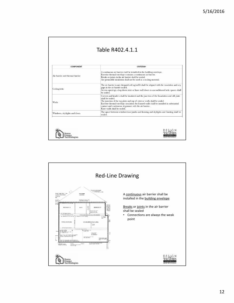
Table R402.4.1.1
• A great builders guide!– If Table 402.4.1.1 is
followed builders should not have difficulty in meeting the < 3 ACH50 requirement
5/16/2016
12
Table R402.4.1.1
Red-Line Drawing
A continuous air barrier shall be installed in the building envelope
Breaks or joints in the air barrier shall be sealed• Connections are always the weak
point

5/16/2016
13
Table R402.4.1.1
Table R402.4.1.1

5/16/2016
14
Critical Air Leakage Points
Joint ACH50
Top plate to attic 0.29 to 1.60
Duct boots 0.13 to 0.26
Recessed lights 0.15 to 0.31
Band joists 0.37 to 0.42
Garage-house common wall 0.14 to 0.26
Sheathing to plate 0.04 to 0.38
Window/door framing to sheathing 0.02 to 0.10
Bottom plate to subfloor 0 to 0.11
Source: Owens Corning Just How Airtight are Your Homes?
Knee wall sealing

5/16/2016
15
Eave vents
Attic rooms

5/16/2016
16
Floor/ceiling blocking & sealing
Floor/ceiling truss blocking
5/16/2016
17
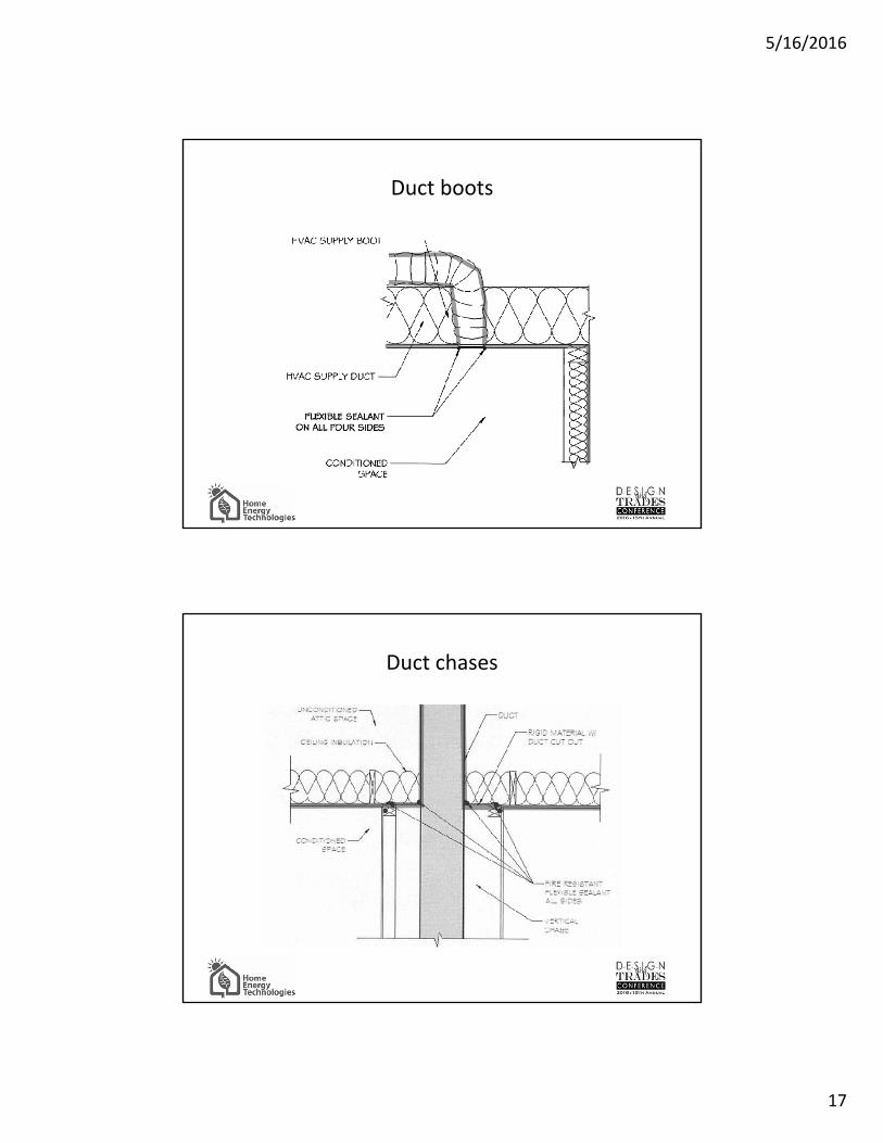
Duct boots
Duct chases
5/16/2016
18
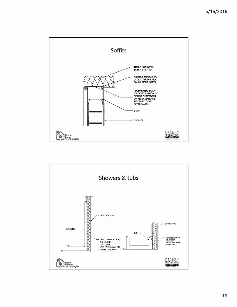
Soffits
Showers & tubs

5/16/2016
19
Gas fireplaces
Blower Door Testing - Equipment
Rings are installed as necessary to ensure adequate air flow for accurate flow readings

5/16/2016
20
Manometer measures pressure differences
• Left channel: Between inside house and the outside
• Right channel: Measures fan pressure– Automatically converted to CFM of air flow
based on ring size used
Manometer
• Code states: – “Testing shall occur after rough-in and after installation of
penetrations in the building envelope, including penetrations for utilities, plumbing, electrical, ventilation and combustion appliances”
• In practice– Test immediately before final CO
• Duct boots sealed to air barrier
• Attic hatch gasketed
• Door & window seals in place
Blower Door Testing - Timing

5/16/2016
21
2009 IECC Section 402.4.2.1 requires that1. Exterior windows and doors, fireplace and stove doors shall be closed but
not sealed
2. Dampers shall be closed, but not sealed, including exhaust, intake, makeup air, backdraft and flue dampers
3. Interior doors shall be open
4. Exterior openings for continuous ventilation systems and heat recovery systems shall be closed and sealed
5. Heating, cooling and ventilation system(s) shall be turned off
6. HVAC ducts shall not be sealed; and
7. Supply and return registers shall not be sealed
Test preparation
RESNET Standard Section 802.5 Procedure for Conducting a One-Point Depressurization Air Tightness Test1. With fan sealed, measure baseline inside/outside pressure differential and set in
manometer
2. Unseal fan, turn on and increase exhaust flow until inside/outside pressure differential equals 50 Pascals
3. Record fan flow in CFM from manometer (minimum 10 second average), inside & outside temperatures, fan and manometer model and serial numbers
4. Calculate corrected CFM50 value if inside/outside ∆T > 30 degrees
Test protocol
While fan is running it is good practice to show builder any notable sources of air infiltration

5/16/2016
22
• ACH50 is the number of complete air exchanges the home would experience in one hour with a 50 Pascal inside/outside pressure differential
• Volume may be calculated from (conditioned floor area) x (average ceiling height)– Includes all volume within the thermal envelope, e.g. insulated
basements and crawlspaces, sealed attics
Interpretation
Benchmarks
ACH50 CFM/sf* ELA (sq. in.) Example
15+ 2.0+ 150 Older homes, balloon framed
10 1.3 100 Recent code-built homes
7 0.93 70 2009 IECC standard
4 0.53 40 ENERGY STAR v3 prescriptive standard
3 0.4 30 2012 &2015 IECC standard
0.6 0.08 6 Passive House standard
0.05 0.007 0.5 Claimed record (Dillingham, Alaska)
* 8’ ceiling height

5/16/2016
23
The natural rate of air exchange (ACHn) can be estimated from the ACH50 results:
ACHn = ACH50 ∕ n
In Connecticut, for a normally exposed, 2-story building n=14.8 so
7 ACH50 = (7/14.8) ACHn = 0.47 ACHn
and
3 ACH50 = (3/14.8) ACHn = 0.20 ACHn
ACH50 and ACHn
• Additions– Generally impossible to isolate old and new construction in
one building
• Multi-family units– Most infiltration is from adjacent units and common spaces
– Compartmentalization is critical. Demising building assemblies must be airsealed to exterior wall standards
Testing challenges

5/16/2016
24
Blower door may identify specific problem areas
Treat drywall as the air barrier
• Seal duct boots and recessed lights
• Seal baseboard and trim
• Seal electrical outlets & plumbing penetrations
• Seal top plate-attic joints
Insulate the basement to bring it inside the conditioned volume
What if I fail?
Duct Leakage - Mandatory
2009 IECC 2012 IECC
Post ConstructionDLO ≤ 8 CFM25/100SF orTDL ≤ 12 CFM25/100 SF
OrRough In
TDL ≤6 CFM25/100 SF including air handler or
TDL ≤ 4 CFM25/100SF excluding air handler
Post ConstructionTDL ≤4 CFM/100SF
OrRough In
TDL ≤ 4 CFM/100 SF including air handler or
TDL ≤ 3 CFM25/100SF excluding air handler
Duct leakage testing not required if air handler and all ductwork are inside the conditioned space

5/16/2016
25
• Duct testing is done at 25 Pascals (0.1” wc), similar to normal operating pressure
• Total Duct Leakage– All leakage from the duct system regardless of whether the loss is to
conditioned or unconditioned space
• Leakage to Outside– That part of total duct leakage that is outside the conditioned space
Leakage Test Types
Duct Leakage Testing - Equipment
5/16/2016
26
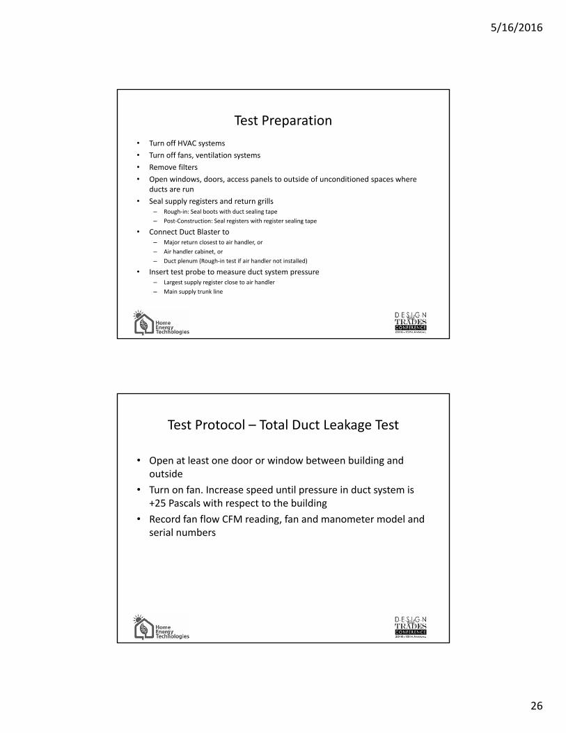
• Turn off HVAC systems
• Turn off fans, ventilation systems
• Remove filters
• Open windows, doors, access panels to outside of unconditioned spaces where ducts are run
• Seal supply registers and return grills– Rough-in: Seal boots with duct sealing tape
– Post-Construction: Seal registers with register sealing tape
• Connect Duct Blaster to– Major return closest to air handler, or
– Air handler cabinet, or
– Duct plenum (Rough-in test if air handler not installed)
• Insert test probe to measure duct system pressure– Largest supply register close to air handler
– Main supply trunk line
Test Preparation
• Open at least one door or window between building and outside
• Turn on fan. Increase speed until pressure in duct system is +25 Pascals with respect to the building
• Record fan flow CFM reading, fan and manometer model and serial numbers
Test Protocol – Total Duct Leakage Test

5/16/2016
27
• Ensure all doors and windows to outside are closed
• Reverse direction of blower door fan (installed as for blower door test) so that building will be pressurized rather than depressurized
• Turn on blower door fan. Increase speed to make building pressure +25 Pascals with respect to outside
– Pressure in duct system will be negative with respect to the building if there is any leakage outside the conditioned space
• Turn on and increase Duct Blaster fan speed to blow air into duct system until the pressure in the duct system is equal to the building pressure (zero pressure differential)
• Record fan flow CFM, fan and manometer model and serial numbers
Test Protocol – Leakage to Outside Test
Duct leakage test result is normalized for building size by dividing by the Conditioned Floor Area:
Interpretation
Leakage/100 sf CFA = CFM25 Leakage Test ResultConditioned Floor Area

5/16/2016
28
Failures
The vast majority of failures are due to the contractor’s failure to seal the duct boots to the building thermal/pressure envelope allowing leakage into unconditioned spaces. Fortunately this is (usually) easy to correct
Less common problems are due to:- Toe kick ducts not connected- Buried ducts- Disconnected fittings- Unsealed connections
• Keep all ducts and air handlers in conditioned space
• Test ducts at rough-in– Problems easier to find and fix
– Sealing boots during installation keeps duct systems clean
– OK for code compliance, ENERGY STAR still requires post construction testing
• Use mastic!
• Ensure boots are sealed to floor or drywall– Ensure cabinet installer aware of proper toe kick duct installation
requirements
Recommendations

5/16/2016
29
• Duct and Envelope Tightness standards account for the majority of the energy efficiency gains in the 2009 and 2012 IECC– 2009 Standards: A learning opportunity
– 2012 Standards: The bar is raised
• Reducing Duct and Envelope Leakage is the most cost effective energy efficiency improvement in most homes– Success requires paying attention to details, not expensive upgrades
Recap
The CT Energy Efficiency Fund offers a $300 incentive for homes that meet the 2009 IECC Duct & Envelope tightness standards.
Testing must be performed by a qualified verifier. Applications and information may be obtained at www.EnergizeCT.com.
Incentives for Duct & Envelope Tightness Testing

5/16/2016
30
Peter Harding
Home Energy Technologies LLC
(877) 800-6440
www.homeenergytechnologies.com
Questions?


