
2011 REV SAE SpaceFrame Waterman
61
1 Design and Construction of a Space-frame Chassis Brendan. J. Waterman 20348559 School of Mechanical and Chemical Engineering University of Western Australia Supervisor: Assoc/Prof Adam Wittek School of Mechanical and Chemical Engineering University of Western Australia Final Year Project Thesis School of Mechanical and Chemical Engineering University of Western Australia Submitted: November 7 th , 2011
-
Upload
arunachelam -
Category
Documents
-
view
269 -
download
5
Transcript of 2011 REV SAE SpaceFrame Waterman
7/27/2019 2011 REV SAE SpaceFrame Waterman
http://slidepdf.com/reader/full/2011-rev-sae-spaceframe-waterman 1/61
1
Design and Construction of a Space-frame
Chassis
Brendan. J. Waterman
20348559
School of Mechanical and Chemical Engineering
University of Western Australia
Supervisor: Assoc/Prof Adam Wittek
School of Mechanical and Chemical Engineering
University of Western Australia
Final Year Project Thesis
School of Mechanical and Chemical Engineering
University of Western Australia
Submitted: November 7
th
, 2011
7/27/2019 2011 REV SAE SpaceFrame Waterman
http://slidepdf.com/reader/full/2011-rev-sae-spaceframe-waterman 2/61
2
Abstract
The purpose of this project is to design and build a space-frame chassis for a race car to
compete in the FSAE-A competition as part of the UWA REV team. The FSAEcompetition is a competition for university students to design, build and race their own
open wheeled race cars, there are also a number of static design events in the
competition. The 2011 REV FSAE car will be powered by four electric motors with one
mounted to each wheel’s upright. This is a new configuration for a FSAE car and as
such requires an entirely new chassis design that both supports the loads placed on it but
also weighs as little as possible. The chassis design implements structural battery boxes
which have the dual purpose of protecting the driver from the batteries and addingstrength to the frame, this has not previously been used in any other FSAE car. Using
these stressed battery boxes gives the chassis excellent torsional stiffness, yet the entire
frame still weighs just over 40kg.
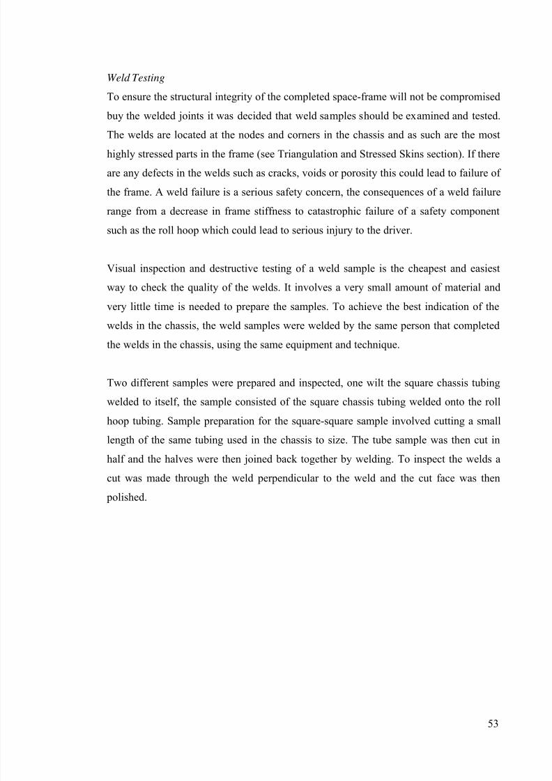
7/27/2019 2011 REV SAE SpaceFrame Waterman
http://slidepdf.com/reader/full/2011-rev-sae-spaceframe-waterman 3/61
4
Acknowledgements
I would like to thank Adam Wittek for his advice throughout this project, the REV team
and Swan Energy for funding the team for which the chassis has been designed, IanHooper for assisting with and providing the tools and facilities used for construction and
Ed Farrar for aiding in and providing the press used for weld testing. Finally I would
like to thank my family and partner for their support throughout the duration of my
studies.
7/27/2019 2011 REV SAE SpaceFrame Waterman
http://slidepdf.com/reader/full/2011-rev-sae-spaceframe-waterman 4/61
5
Contents
Abstract ............................................................................................................................. 2
Letter of Transmittal ......................................................................................................... 3
Acknowledgements ........................................................................................................... 4
Introduction ....................................................................................................................... 7
Literature Review ............................................................................................................ 10
Design Process ................................................................................................................ 11
Rules ............................................................................................................................ 11
Suspension Design and Forces .................................................................................... 15
Packaging .................................................................................................................... 17
Material ....................................................................................................................... 17
Manufacture ................................................................................................................ 18
Square vs Round ......................................................................................................... 19
Triangulation and Stressed Skins ................................................................................ 20
Stressed Battery Boxes ................................................................................................ 24
Final Design .................................................................................................................... 27
Front and rear sections ................................................................................................ 27
Roll hoops ................................................................................................................... 33
Side impact structure ................................................................................................... 37
Front Bulkhead and Foot-well .................................................................................... 38
Completing the Space-Frame ...................................................................................... 39
Battery boxes ............................................................................................................... 40
Final Design Summary .................................................................................................... 41
Construction .................................................................................................................... 42
Welding ....................................................................................................................... 42
Construction Process ................................................................................................... 43
Work completed .......................................................................................................... 48
7/27/2019 2011 REV SAE SpaceFrame Waterman
http://slidepdf.com/reader/full/2011-rev-sae-spaceframe-waterman 5/61
6
Safety............................................................................................................................... 49
Construction ................................................................................................................ 49
Operation of the completed chassis ............................................................................ 51
Torsion testing ............................................................................................................. 52
Weld Testing ............................................................................................................... 53
Conclusion ...................................................................................................................... 59
Future work ..................................................................................................................... 60
Construction ................................................................................................................ 60
Chassis testing ............................................................................................................. 60
Ultrasonic weld testing ................................................................................................ 60
Tuning ......................................................................................................................... 60
Future designs ............................................................................................................. 61
References ....................................................................................................................... 62

7/27/2019 2011 REV SAE SpaceFrame Waterman
http://slidepdf.com/reader/full/2011-rev-sae-spaceframe-waterman 6/61
7
Introduction
The purpose of this project is to design and construct a chassis for an electric powered
Formula SAE (FSAE) car to compete in the December 2011 FSAE-A competition. The
competition is for students to design, build and race small open-wheeled race cars
against the clock in a number of events. The competition also includes some static
design events, where the cost and design of the car is judged by a panel. A unique
chassis design is required as the car will be powered by four electric hub motors, as
opposed to the more conventional internal combustion engine mounted within the
frame. This is the first time that electric hub motors will be used in the Australian F-
SAE competition and the first time four wheel-hub motors have been used in any FSAE
competition around the world.
In 2010 the REV team converted a previously used petrol FSAE chassis to electric
power in a similar configuration to the conventional combustion engine configuration.
The chassis was made by UWA Motorsports and competed in the 2002 F-SAE
competition. It was never intended for this petrol to electric converted car to compete in
any FSAE event as it was only done as a prototyping exercise in an effort to investigate
the potential of an electric F-SAE car. The chassis no longer meets the requirements for
the FSAE competition as the rules for the competition have changed since 2002.
Figure 1 2001 UWAM Chassis converted to electric power using a conventional inboard enginelayout
7/27/2019 2011 REV SAE SpaceFrame Waterman
http://slidepdf.com/reader/full/2011-rev-sae-spaceframe-waterman 7/61
8
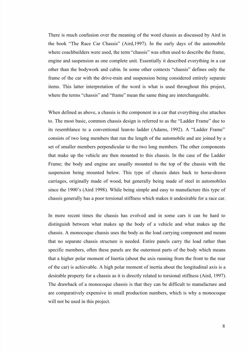
There is much confusion over the meaning of the word chassis as discussed by Aird in
the book “The Race Car Chassis” (Aird,1997). In the early days of the automobile
where coachbuilders were used, the term “chassis” was often used to describe the frame,
engine and suspension as one complete unit. Essentially it described everything in a car other than the bodywork and cabin. In some other contexts “chassis” defines only the
frame of the car with the drive-train and suspension being considered entirely separate
items. This latter interpretation of the word is what is used throughout this project,
where the terms “chassis” and “frame” mean the same thing are interchangeable.
When defined as above, a chassis is the component in a car that everything else attaches
to. The most basic, common chassis design is referred to as the “Ladder Frame” due toits resemblance to a conventional lean-to ladder (Adams, 1992). A “Ladder Frame”
consists of two long members that run the length of the automobile and are joined by a
set of smaller members perpendicular to the two long members. The other components
that make up the vehicle are then mounted to this chassis. In the case of the Ladder
Frame; the body and engine are usually mounted to the top of the chassis with the
suspension being mounted below. This type of chassis dates back to horse-drawn
carriages, originally made of wood, but generally being made of steel in automobiles
since the 1900’s (Aird 1998). While being simple and easy to manufacture this type of
chassis generally has a poor torsional stiffness which makes it undesirable for a race car.
In more recent times the chassis has evolved and in some cars it can be hard to
distinguish between what makes up the body of a vehicle and what makes up the
chassis. A monocoque chassis uses the body as the load carrying component and means
that no separate chassis structure is needed. Entire panels carry the load rather than
specific members, often these panels are the outermost parts of the body which means
that a higher polar moment of Inertia (about the axis running from the front to the rear
of the car) is achievable. A high polar moment of inertia about the longitudinal axis is a
desirable property for a chassis as it is directly related to torsional stiffness (Aird, 1997).
The drawback of a monocoque chassis is that they can be difficult to manufacture and
are comparatively expensive in small production numbers, which is why a monocoque
will not be used in this project.
7/27/2019 2011 REV SAE SpaceFrame Waterman
http://slidepdf.com/reader/full/2011-rev-sae-spaceframe-waterman 8/61
9
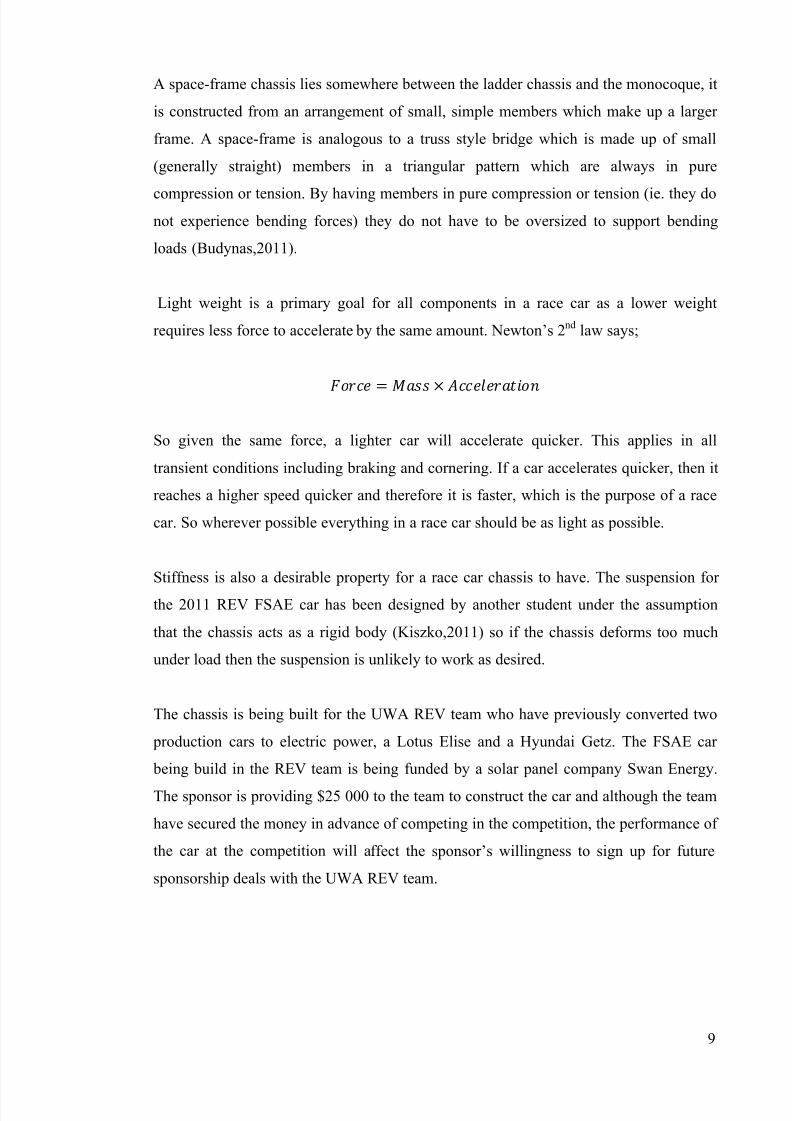
A space-frame chassis lies somewhere between the ladder chassis and the monocoque, it
is constructed from an arrangement of small, simple members which make up a larger
frame. A space-frame is analogous to a truss style bridge which is made up of small
(generally straight) members in a triangular pattern which are always in pure
compression or tension. By having members in pure compression or tension (ie. they donot experience bending forces) they do not have to be oversized to support bending
loads (Budynas,2011).
Light weight is a primary goal for all components in a race car as a lower weight
requires less force to accelerate by the same amount. Newton’s 2nd law says;
= ×
So given the same force, a lighter car will accelerate quicker. This applies in all
transient conditions including braking and cornering. If a car accelerates quicker, then it
reaches a higher speed quicker and therefore it is faster, which is the purpose of a race
car. So wherever possible everything in a race car should be as light as possible.
Stiffness is also a desirable property for a race car chassis to have. The suspension for
the 2011 REV FSAE car has been designed by another student under the assumption
that the chassis acts as a rigid body (Kiszko,2011) so if the chassis deforms too much
under load then the suspension is unlikely to work as desired.
The chassis is being built for the UWA REV team who have previously converted two
production cars to electric power, a Lotus Elise and a Hyundai Getz. The FSAE car
being build in the REV team is being funded by a solar panel company Swan Energy.
The sponsor is providing $25 000 to the team to construct the car and although the team
have secured the money in advance of competing in the competition, the performance of
the car at the competition will affect the sponsor’s willingness to sign up for future
sponsorship deals with the UWA REV team.
7/27/2019 2011 REV SAE SpaceFrame Waterman
http://slidepdf.com/reader/full/2011-rev-sae-spaceframe-waterman 9/61
10
Literature Review
Before commencing any design work it is useful to see what is already being done by
others in the same field. As mentioned in the introduction the 2011 REV FSAE car will
be powered by a unique drive-train and as such requires a unique chassis, however the basic principles of chassis design still apply.
For a background into chassis design a relevant text was discovered and reviewed. The
book published by Penguin Books is entitled “The Race Car Chassis” and is written by
Forbes Aird. The book discusses different types of chassis’ and the history of chassis
evolution. It focuses primarily on space-frames and stressed skin type chassis’ which is
highly relevant to this project due to the low cost, readily available materials used andrelatively simple manufacturing processes. “The Race Car Chassis” is somewhat of a
review of different chassis designs used by different race cars, discussing chassis’ from
all manner of classes such as drag, circle track and even passenger cars. The book also
covers the different materials commonly used to construct chassis’ and lists each
material’s advantages and disadvantages. Aird includes information regarding
suspension and other loads on the chassis and how these should be supported.
Significantly the book covers the design process for space-frame chassis’ including
material selection, tube sizing and member arrangement. “The Race Car Chassis” was
originally written in 1997 which means it is not up to date with the latest and most
advanced technology however space-frames have not changed significantly in recent
years so the book is still highly relevant. The main advancements that have been made
in chassis technology since 1997 are in composite monocoque frames which are not
relevant to this project due to their relatively high cost and the REV team’s limited
budget. Overall this is a very useful book for the project covering much relevant
information without any significant bias.
Another text that was analysed for this project was “Chassis Engineering” written by
Herb Adams and published by Penguin Books. The book was first published in 1992
making it slightly older than “The Race Car Chassis” described above. Contrary to Aird
and this project, Adams considers the chassis to include suspension and bodywork
components so the book contains a large amount of information about suspension setup
and tuning as well as tyre characteristics which is not relevant for this project as the
suspension for the car has already been designed by another student. Much of the frame
7/27/2019 2011 REV SAE SpaceFrame Waterman
http://slidepdf.com/reader/full/2011-rev-sae-spaceframe-waterman 10/61
11
design information covered in this book is the same as found in “The Race Car Chassis”
which serves to validate and confirm the information already found rather than actually
providing any new information. This does not make the book useless though as it is
useful to have a second source back up the information already gathered. “Chassis
Engineering” does include some useful pictures of various chassis design models beingtested in torsion which serve to give a good idea of what designs work well and which
ones don’t. This information is not quantitative and cannont be directly applied in the
design process, but it is likely to be useful in that the design will have a better starting
point.
The University of Western Australia has a history of competing at the FSAE event
successfully. UWA Motorsport (UWAM) has been competing at the event since 2001,winning the Australian competition in 2005 and 2007 and even winning the
international competition in 2008. UWAM has been using carbon fibre monocoque
chassis’ since 2003, as discussed earlier the 2011 UWA REV team would not be using a
carbon monocoque due to the cost associated.
Design Process
Design Requirements
The design of the chassis must work around a number of parameters and constraints in
order for it to perform well and for it to be eligible to compete in the competition. These
requirements can be broken into several categories which will be discussed below. If
any of these requirements are not met, the consequences range from sub-optimal
performance to not being eligible to compete in the competition or even chassis failure.
So it is clear that all requirements must be carefully considered and even re-visited
when designing and building the chassis.
Rules
The first thing that must be considered when designing the chassis is the 2011 FSAE-A
rules, there is no point in designing a chassis if it will not be allowed to compete in the
competition for which it is designed. The FSAE rules require a front and rear roll hoop,
a side impact structure, a front bulkhead and supports for the aforementioned
components be integrated into the chassis. By representing graphically these
7/27/2019 2011 REV SAE SpaceFrame Waterman
http://slidepdf.com/reader/full/2011-rev-sae-spaceframe-waterman 11/61
12
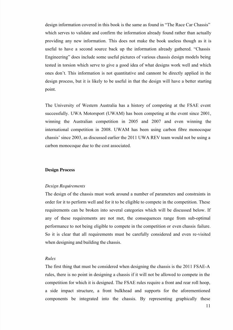
requirements one may create a “minimum chassis’ Figure 2 which shows the simplest
possible configuration of members that include the required components mentioned
above. Figure 2 is a side view diagram of what this “minimum chassis” looks like, i t
does not consider driver ergonomics, cockpit entry or suspension points etc, and is
merely a pictorial representation of some of the required members.
Figure 2. Pictorial representation of the members required by the FSAE rules.
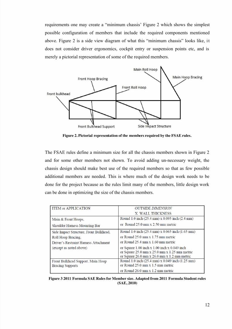
The FSAE rules define a minimum size for all the chassis members shown in Figure 2
and for some other members not shown. To avoid adding un-necessary weight, the
chassis design should make best use of the required members so that as few possible
additional members are needed. This is where much of the design work needs to be
done for the project because as the rules limit many of the members, little design work
can be done in optimizing the size of the chassis members.
Figure 3 2011 Formula SAE Rules for Member size. Adapted from 2011 Formula Student rules
(SAE, 2010)
7/27/2019 2011 REV SAE SpaceFrame Waterman
http://slidepdf.com/reader/full/2011-rev-sae-spaceframe-waterman 12/61
13
The FSAE rules also require a firewall barrier to isolate the batteries from the driver, it
must cover the vertical and horizontal portions of the battery box that face the driver.
2.6mm aluminium sheet is suggested for this firewall but 1mm steel has been approved
as an alternative by the FSAE-A rules committee. The chassis must also provide
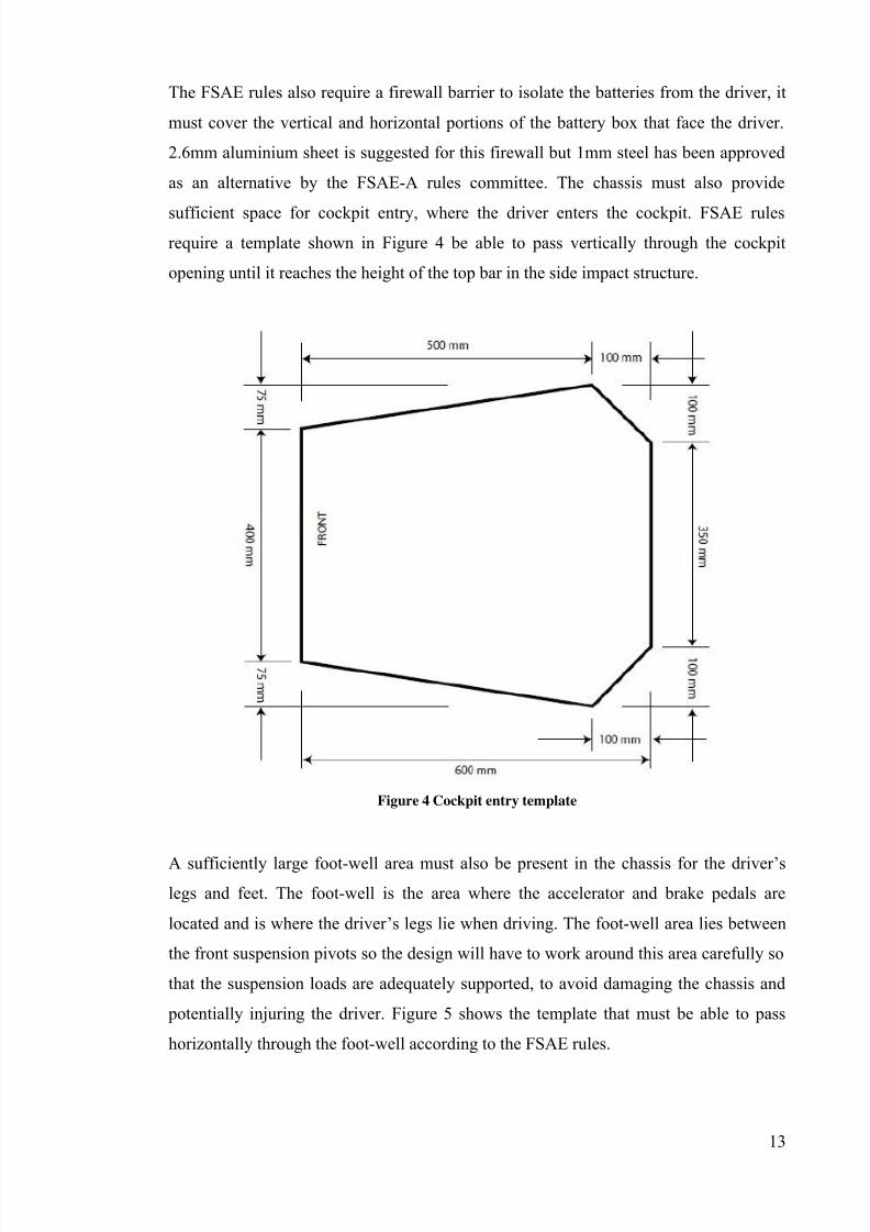
sufficient space for cockpit entry, where the driver enters the cockpit. FSAE rules
require a template shown in Figure 4 be able to pass vertically through the cockpit
opening until it reaches the height of the top bar in the side impact structure.
Figure 4 Cockpit entry template
A sufficiently large foot-well area must also be present in the chassis for the driver ’s
legs and feet. The foot-well is the area where the accelerator and brake pedals are
located and is where the driver ’s legs lie when driving. The foot-well area lies between
the front suspension pivots so the design will have to work around this area carefully so
that the suspension loads are adequately supported, to avoid damaging the chassis and
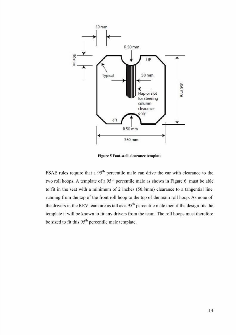
potentially injuring the driver. Figure 5 shows the template that must be able to pass
horizontally through the foot-well according to the FSAE rules.
7/27/2019 2011 REV SAE SpaceFrame Waterman
http://slidepdf.com/reader/full/2011-rev-sae-spaceframe-waterman 13/61
14
Figure 5 Foot-well clearance template
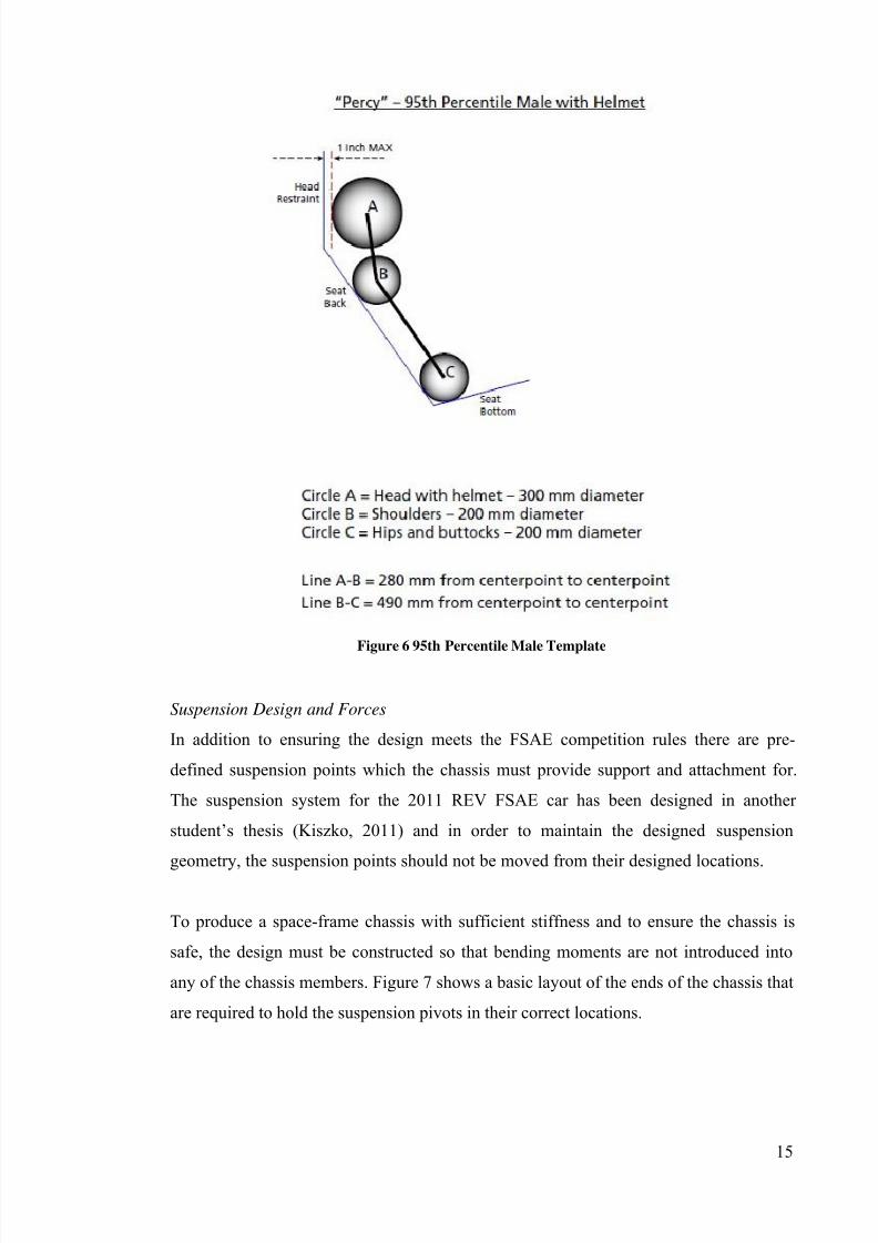
FSAE rules require that a 95th percentile male can drive the car with clearance to the
two roll hoops. A template of a 95 th percentile male as shown in Figure 6 must be able
to fit in the seat with a minimum of 2 inches (50.8mm) clearance to a tangential line
running from the top of the front roll hoop to the top of the main roll hoop. As none of
the drivers in the REV team are as tall as a 95th percentile male then if the design fits the
template it will be known to fit any drivers from the team. The roll hoops must therefore
be sized to fit this 95th percentile male template.
7/27/2019 2011 REV SAE SpaceFrame Waterman
http://slidepdf.com/reader/full/2011-rev-sae-spaceframe-waterman 14/61
15
Figure 6 95th Percentile Male Template
Suspension Design and Forces
In addition to ensuring the design meets the FSAE competition rules there are pre-
defined suspension points which the chassis must provide support and attachment for.
The suspension system for the 2011 REV FSAE car has been designed in another
student’s thesis (Kiszko, 2011) and in order to maintain the designed suspension
geometry, the suspension points should not be moved from their designed locations.
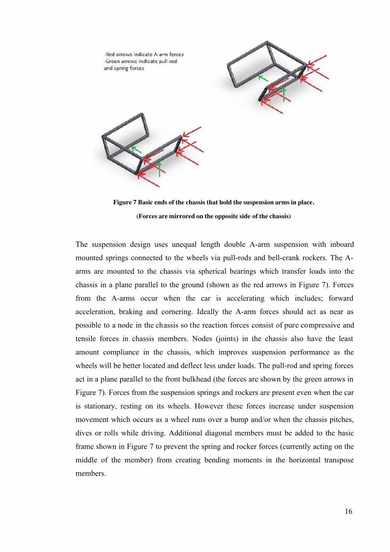
To produce a space-frame chassis with sufficient stiffness and to ensure the chassis is
safe, the design must be constructed so that bending moments are not introduced into
any of the chassis members. Figure 7 shows a basic layout of the ends of the chassis that
are required to hold the suspension pivots in their correct locations.
7/27/2019 2011 REV SAE SpaceFrame Waterman
http://slidepdf.com/reader/full/2011-rev-sae-spaceframe-waterman 15/61
16
Figure 7 Basic ends of the chassis that hold the suspension arms in place.
(Forces are mirrored on the opposite side of the chassis)
The suspension design uses unequal length double A-arm suspension with inboard
mounted springs connected to the wheels via pull-rods and bell-crank rockers. The A-
arms are mounted to the chassis via spherical bearings which transfer loads into the
chassis in a plane parallel to the ground (shown as the red arrows in Figure 7). Forces
from the A-arms occur when the car is accelerating which includes; forward
acceleration, braking and cornering. Ideally the A-arm forces should act as near as
possible to a node in the chassis so the reaction forces consist of pure compressive and
tensile forces in chassis members. Nodes (joints) in the chassis also have the least
amount compliance in the chassis, which improves suspension performance as the
wheels will be better located and deflect less under loads. The pull-rod and spring forces
act in a plane parallel to the front bulkhead (the forces are shown by the green arrows in
Figure 7). Forces from the suspension springs and rockers are present even when the car
is stationary, resting on its wheels. However these forces increase under suspension
movement which occurs as a wheel runs over a bump and/or when the chassis pitches,
dives or rolls while driving. Additional diagonal members must be added to the basic
frame shown in Figure 7 to prevent the spring and rocker forces (currently acting on the
middle of the member) from creating bending moments in the horizontal transpose
members.
7/27/2019 2011 REV SAE SpaceFrame Waterman
http://slidepdf.com/reader/full/2011-rev-sae-spaceframe-waterman 16/61
17
Packaging
In conjunction with meeting all the rules and providing attachments for the suspension
components, the chassis must also fit the driver and all the required components into the
frame. The most significant of these components being:
Seat and driver harnesses
Batteries
Electronic control components (motor controllers, BMS, Sensors etc.)
Driver controls (steering wheel, pedals, switches etc)
The driver must be considered first as he/she will be bigger than any other component in
the car and must fit comfortably. Driver ergonomics must be considered to ensure the
driver is able to complete each driving event comfortably. Points are also awarded in thestatic phase of the competition for driver ergonomics so it is beneficial to pay close
attention to this area while designing. As mentioned in the rules section, the 95 th
percentile male must be able to fit in the chassis with clearance to the front and rear roll
hoops so
Fortunately most of the other required components can be made to fit into the small
remaining spaces as their shape is quite flexible. The batteries will be made from 600small cylindrical cells meaning their required volume is significant but their shape can
be made to suit the chassis design. However a relatively simple shape is desirable in
order to prevent un-necessary complexity in connecting the cells. A motor controller is
required to control each of the 4 motors and should be mounted as close to each motor
as practically possible. The motor controllers must be mounted as close to the motor
that they are controlling as possible so the front motor controllers can be mounted to the
back of the front bulkhead, in front of the driver’s feet. The remaining rear motor
controllers and other electronic control units are able to be located in the rear section of
the chassis behind the driver, space which is otherwise unused as the 2011 REV FSAE
car does not have an inboard mounted engine.
Material
It was decided that the frame would be constructed from steel due to its availability and
relatively low cost. There are many different grades of steel available however many of
the FSAE teams around the world from universities such as UWA (for the rear space-
frame section), Curtin, RMIT, Missouri S&T use 4130 SAE grade steel (which contains
7/27/2019 2011 REV SAE SpaceFrame Waterman
http://slidepdf.com/reader/full/2011-rev-sae-spaceframe-waterman 17/61
18
Chromium and Molybdenum alloying elements) due to its higher yield strength. In the
first part of the design phase when the chassis material was chosen, the team had a
limited budget which resulted in the decision to use mild steel instead of 4130.
Lightweight and stiffness are the most important properties of a chassis and the stiffnessof the completed chassis will be affected by the stiffness of the material from which it is
built. Material stiffness is known as Young’s Modulus and the controlling mechanism
for stiffness in a material is the inter-molecular forces. So stiffness or Young’s Modulus
is a material constant which cannot be significantly changed by any mechanical or
chemical processes. Alloying elements also have little effect on stiffness meaning that
more expensive grades of steel have the same stiffness as mild steel (Callister, 2007).
This justifies the decision to use mild steel for chassis construction as more expensivesteels are unlikely to improve the chassis’ stiffness.
Aside from cost there are other advantages to using mild steel over more expensive
alloy steel, it is easy to machine and weld, also it does not become brittle in the heat
affected zone when welding. (Black,2008) The FSAE rules also state that using stronger
steels does not allow the use of smaller chassis members so there would be no weight
advantage in using the more expensive SAE grade 4130 steel for these members. The
downside to using mild steel comes with its lower yield strength, in the event of a
collision or some other impact the chassis may become damaged at a lower stress than if
it were built from 4130. This disadvantage is also present when there are small impacts
on the chassis, an example of this would be small stones being picked up off the road by
the tyres and hitting the chassis. The chassis may dent and its structural integrity may be
compromised easier than an equivalent alloy steel chassis. In order to prevent this from
endangering the driver, routine checks of the chassis for dents and damage must be
made prior to anyone driving the car.
Manufacture
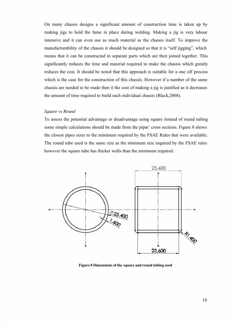
In order to improve manufacturability, square tubing may be used for many of the
horizontal frame members. This makes cutting planar joints easier and simplifies
suspension mounting points. Due to availability 25.4mm x 25.4mm x 1.4mm square
tubing was used, which is larger than the minimum size required by the FSAE rules in
Figure 3.
7/27/2019 2011 REV SAE SpaceFrame Waterman
http://slidepdf.com/reader/full/2011-rev-sae-spaceframe-waterman 18/61
7/27/2019 2011 REV SAE SpaceFrame Waterman
http://slidepdf.com/reader/full/2011-rev-sae-spaceframe-waterman 19/61
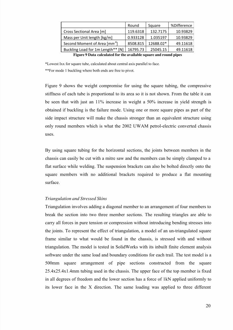
20
Round Square %Difference
Cross Sectional Area [m] 119.6318 132.7175 10.93829
Mass per Unit length [kg/m] 0.933128 1.035197 10.93829
Second Moment of Area [mm4] 8508.815 12688.02* 49.11618
Buckling Load for 1m Length** [N] 16795.73 25045.15 49.11618
Figure 9 Data calculated for the available square and round pipes
*Lowest Ixx for square tube, calculated about central axis parallel to face.
**For mode 1 buckling where both ends are free to pivot.
Figure 9 shows the weight compromise for using the square tubing, the compressive
stiffness of each tube is proportional to its area so it is not shown. From the table it can
be seen that with just an 11% increase in weight a 50% increase in yield strength is
obtained if buckling is the failure mode. Using one or more square pipes as part of the
side impact structure will make the chassis stronger than an equivalent structure using
only round members which is what the 2002 UWAM petrol-electric converted chassis
uses.
By using square tubing for the horizontal sections, the joints between members in the
chassis can easily be cut with a mitre saw and the members can be simply clamped to a
flat surface while welding. The suspension brackets can also be bolted directly onto the
square members with no additional brackets required to produce a flat mounting
surface.
Triangulation and Stressed Skins
Triangulation involves adding a diagonal member to an arrangement of four members to
break the section into two three member sections. The resulting triangles are able to
carry all forces in pure tension or compression without introducing bending stresses into
the joints. To represent the effect of triangulation, a model of an un-triangulated square
frame similar to what would be found in the chassis, is stressed with and without
triangulation. The model is tested in SolidWorks with its inbuilt finite element analysis
software under the same load and boundary conditions for each trail. The test model is a
500mm square arrangement of pipe sections constructed from the square
25.4x25.4x1.4mm tubing used in the chassis. The upper face of the top member is fixed
in all degrees of freedom and the lower section has a force of 1kN applied uniformly to
its lower face in the X direction. The same loading was applied to three different
7/27/2019 2011 REV SAE SpaceFrame Waterman
http://slidepdf.com/reader/full/2011-rev-sae-spaceframe-waterman 20/61
21
iterations of the same basic structure and the maximum displacement and maximum
Von-Mises stress was recorded.
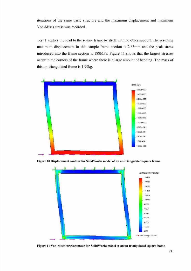
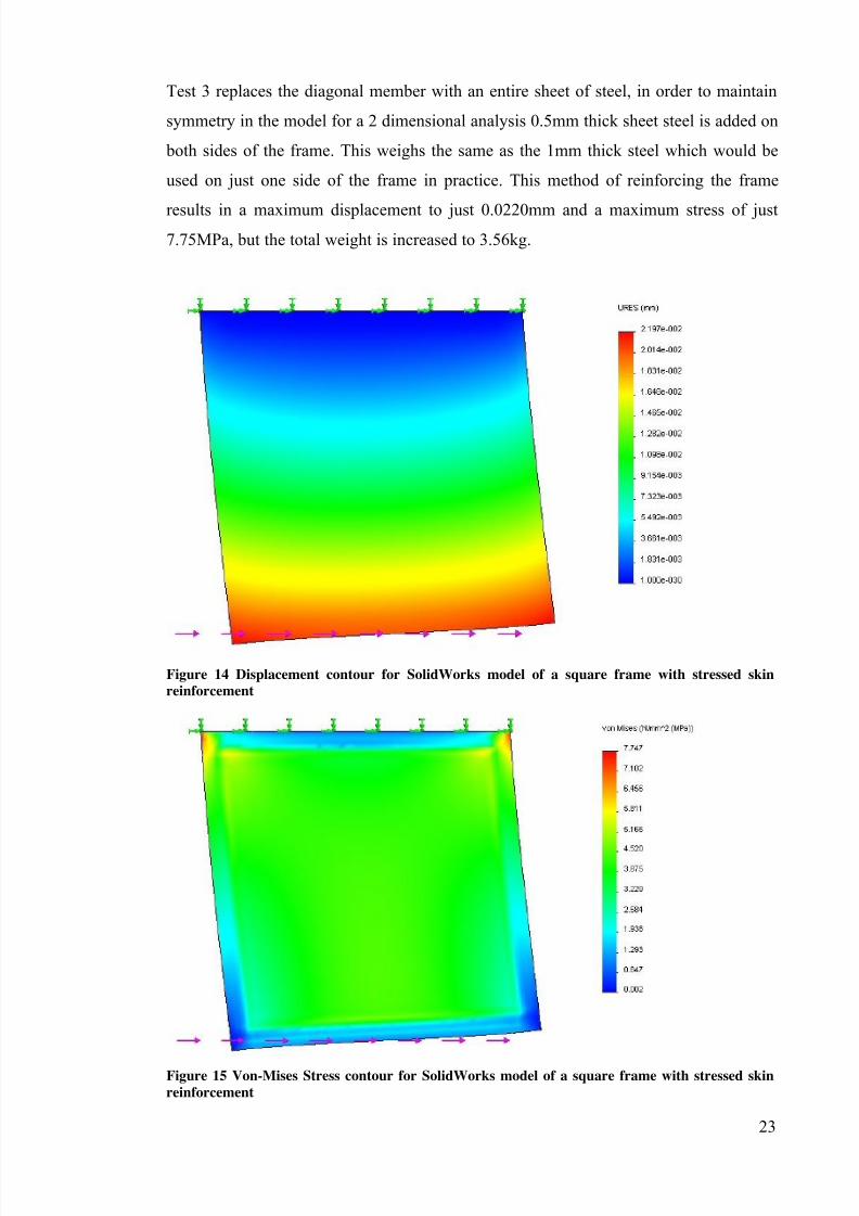
Test 1 applies the load to the square frame by itself with no other support. The resulting
maximum displacement in this sample frame section is 2.65mm and the peak stressintroduced into the frame section is 188MPa, Figure 11 shows that the largest stresses
occur in the corners of the frame where there is a large amount of bending. The mass of
this un-triangulated frame is 1.99kg.
Figure 10 Displacement contour for SolidWorks model of an un-triangulated square frame
Figure 11 Von-Mises stress contour for SolidWorks model of an un-triangulated square frame
7/27/2019 2011 REV SAE SpaceFrame Waterman
http://slidepdf.com/reader/full/2011-rev-sae-spaceframe-waterman 21/61
22
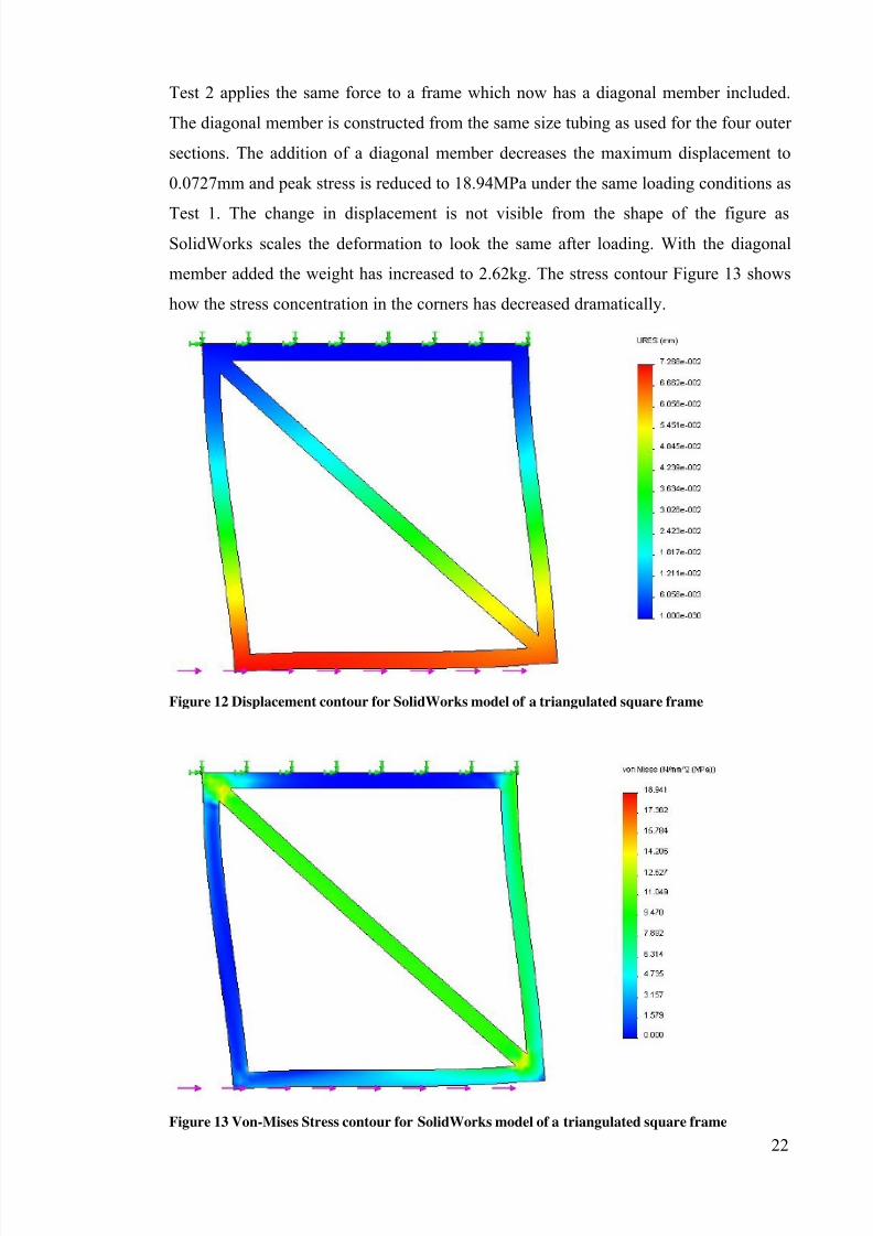
Test 2 applies the same force to a frame which now has a diagonal member included.
The diagonal member is constructed from the same size tubing as used for the four outer
sections. The addition of a diagonal member decreases the maximum displacement to
0.0727mm and peak stress is reduced to 18.94MPa under the same loading conditions as
Test 1. The change in displacement is not visible from the shape of the figure asSolidWorks scales the deformation to look the same after loading. With the diagonal
member added the weight has increased to 2.62kg. The stress contour Figure 13 shows
how the stress concentration in the corners has decreased dramatically.
Figure 12 Displacement contour for SolidWorks model of a triangulated square frame
Figure 13 Von-Mises Stress contour for SolidWorks model of a triangulated square frame
7/27/2019 2011 REV SAE SpaceFrame Waterman
http://slidepdf.com/reader/full/2011-rev-sae-spaceframe-waterman 22/61
7/27/2019 2011 REV SAE SpaceFrame Waterman
http://slidepdf.com/reader/full/2011-rev-sae-spaceframe-waterman 23/61
24
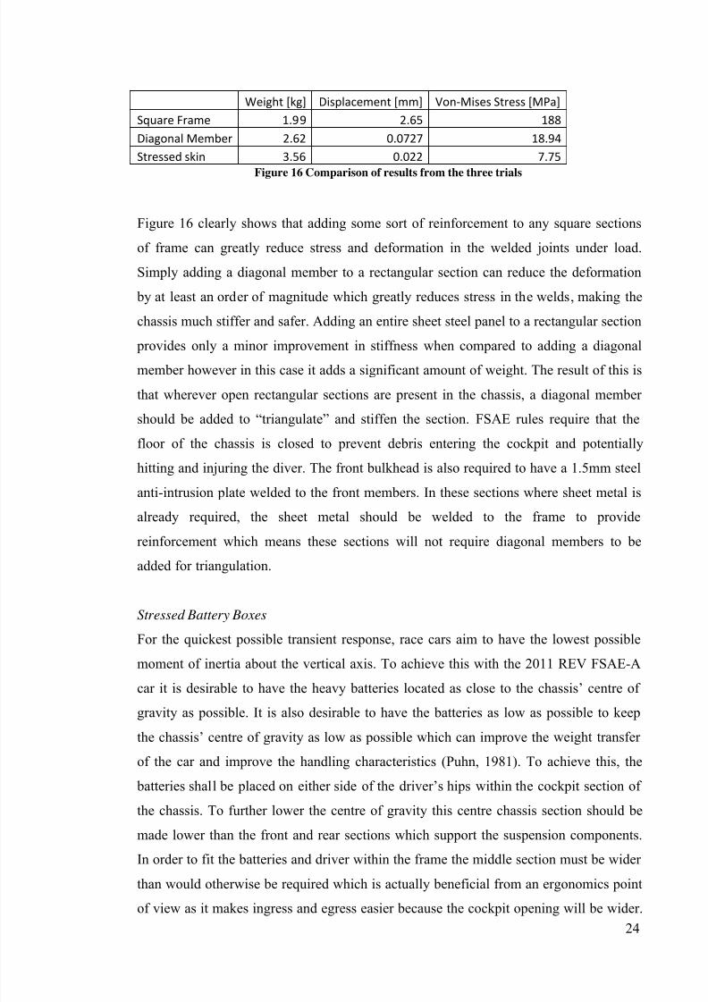
Weight [kg] Displacement [mm] Von-Mises Stress [MPa]
Square Frame 1.99 2.65 188
Diagonal Member 2.62 0.0727 18.94
Stressed skin 3.56 0.022 7.75
Figure 16 Comparison of results from the three trials
Figure 16 clearly shows that adding some sort of reinforcement to any square sections
of frame can greatly reduce stress and deformation in the welded joints under load.
Simply adding a diagonal member to a rectangular section can reduce the deformation
by at least an order of magnitude which greatly reduces stress in the welds, making the
chassis much stiffer and safer. Adding an entire sheet steel panel to a rectangular section
provides only a minor improvement in stiffness when compared to adding a diagonalmember however in this case it adds a significant amount of weight. The result of this is
that wherever open rectangular sections are present in the chassis, a diagonal member
should be added to “triangulate” and stiffen the section. FSAE rules require that the
floor of the chassis is closed to prevent debris entering the cockpit and potentially
hitting and injuring the diver. The front bulkhead is also required to have a 1.5mm steel
anti-intrusion plate welded to the front members. In these sections where sheet metal is
already required, the sheet metal should be welded to the frame to provide
reinforcement which means these sections will not require diagonal members to be
added for triangulation.
Stressed Battery Boxes
For the quickest possible transient response, race cars aim to have the lowest possible
moment of inertia about the vertical axis. To achieve this with the 2011 REV FSAE-A
car it is desirable to have the heavy batteries located as close to the chassis’ centre of
gravity as possible. It is also desirable to have the batteries as low as possible to keep
the chassis’ centre of gravity as low as possible which can improve the weight transfer
of the car and improve the handling characteristics (Puhn, 1981). To achieve this, the
batteries shall be placed on either side of the driver’s hips within the cockpit section of
the chassis. To further lower the centre of gravity this centre chassis section should be
made lower than the front and rear sections which support the suspension components.
In order to fit the batteries and driver within the frame the middle section must be wider
than would otherwise be required which is actually beneficial from an ergonomics point
of view as it makes ingress and egress easier because the cockpit opening will be wider.
7/27/2019 2011 REV SAE SpaceFrame Waterman
http://slidepdf.com/reader/full/2011-rev-sae-spaceframe-waterman 24/61
25
Having a wider chassis also means the chassis easily meets the requirements for the
cockpit opening Figure 4.
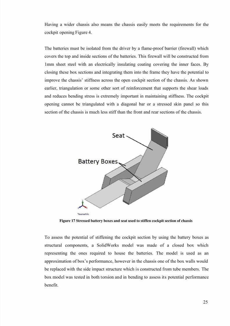
The batteries must be isolated from the driver by a flame-proof barrier (firewall) which
covers the top and inside sections of the batteries. This firewall will be constructed from1mm sheet steel with an electrically insulating coating covering the inner faces. By
closing these box sections and integrating them into the frame they have the potential to
improve the chassis’ stiffness across the open cockpit section of the chassis. As shown
earlier, triangulation or some other sort of reinforcement that supports the shear loads
and reduces bending stress is extremely important in maintaining stiffness. The cockpit
opening cannot be triangulated with a diagonal bar or a stressed skin panel so this
section of the chassis is much less stiff than the front and rear sections of the chassis.
Figure 17 Stressed battery boxes and seat used to stiffen cockpit section of chassis
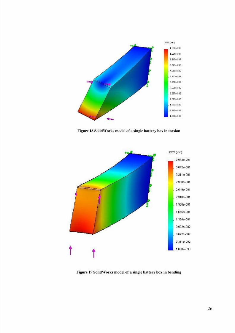
To assess the potential of stiffening the cockpit section by using the battery boxes as
structural components, a SolidWorks model was made of a closed box which
representing the ones required to house the batteries. The model is used as an
approximation of box’s performance, however in the chassis one of the box walls would
be replaced with the side impact structure which is constructed from tube members. The
box model was tested in both torsion and in bending to assess its potential performance
benefit.
7/27/2019 2011 REV SAE SpaceFrame Waterman
http://slidepdf.com/reader/full/2011-rev-sae-spaceframe-waterman 25/61
26
Figure 18 SolidWorks model of a single battery box in torsion
Figure 19 SolidWorks model of a single battery box in bending
7/27/2019 2011 REV SAE SpaceFrame Waterman
http://slidepdf.com/reader/full/2011-rev-sae-spaceframe-waterman 26/61
27
The SolidWorks model of a single battery box showed that each box had a torsional
stiffness of roughly 10000Nm/degree. However the bending simulation is more likely to
give a better representation of how the battery boxes are likely to improve the chassis
performance. The vertical applied force is multiplied by the distance to the vehicle
centreline to get a torque and the vertical displacement divided by the distance gives thetangent of the twist angle, thus a torsional stiffness of 6600Nm/degree is obtained for
the two battery boxes as they would be mounted in the chassis. This stiffness would
significantly increase the stiffness of the open cockpit section so it is worthwhile
investing the extra time to integrate the boxes into the frame as a structural component.
As the firewall(s) are constructed form steel they can be welded straight to the chassis
members rather than using fixing screws/bolts, which can work loose over time.
The FSAE rules also require a side impact structure be present on the outside of the
battery boxes so by placing them within the cockpit section where a side impact
structure is already present, there is no need to add a second side impact structure
elsewhere just for the batteries which would add otherwise un-necessary weight.
To further improve the effect of using the battery boxes as structural components to
stiffen the cockpit section, the seat should be welded to these battery boxes to increase
the stiffness of the assembly. This would also add support to the large side faces of the
boxes to prevent them from buckling.
Final Design
Front and rear sections
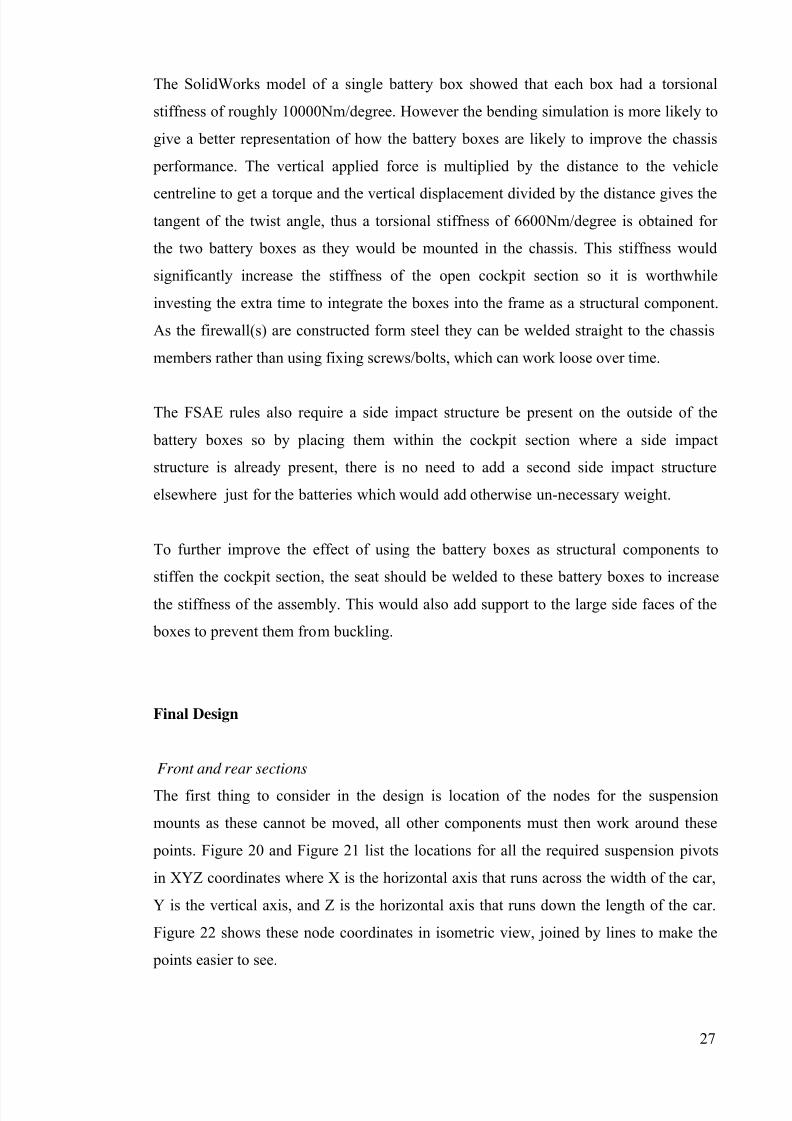
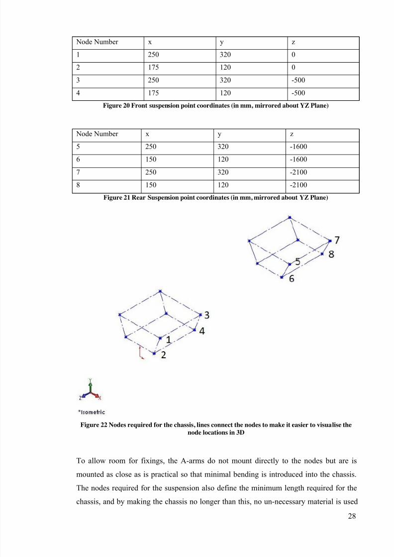
The first thing to consider in the design is location of the nodes for the suspension
mounts as these cannot be moved, all other components must then work around these
points. Figure 20 and Figure 21 list the locations for all the required suspension pivots
in XYZ coordinates where X is the horizontal axis that runs across the width of the car,
Y is the vertical axis, and Z is the horizontal axis that runs down the length of the car.
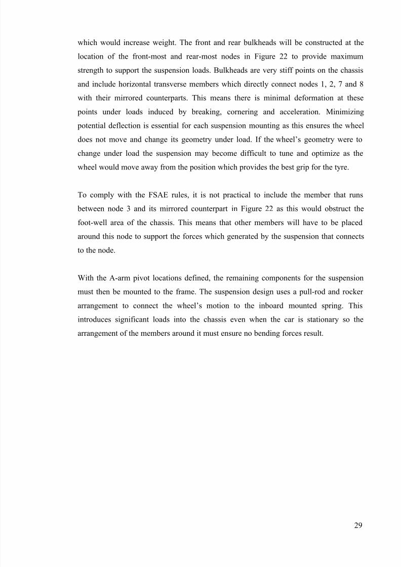
Figure 22 shows these node coordinates in isometric view, joined by lines to make the
points easier to see.
7/27/2019 2011 REV SAE SpaceFrame Waterman
http://slidepdf.com/reader/full/2011-rev-sae-spaceframe-waterman 27/61
28
Node Number x y z
1 250 320 0
2 175 120 0
3 250 320 -500
4 175 120 -500
Figure 20 Front suspension point coordinates (in mm, mirrored about YZ Plane)
Node Number x y z
5 250 320 -1600
6 150 120 -1600
7 250 320 -2100
8 150 120 -2100
Figure 21 Rear Suspension point coordinates (in mm, mirrored about YZ Plane)
Figure 22 Nodes required for the chassis, lines connect the nodes to make it easier to visualise the
node locations in 3D
To allow room for fixings, the A-arms do not mount directly to the nodes but are is
mounted as close as is practical so that minimal bending is introduced into the chassis.
The nodes required for the suspension also define the minimum length required for the
chassis, and by making the chassis no longer than this, no un-necessary material is used
7/27/2019 2011 REV SAE SpaceFrame Waterman
http://slidepdf.com/reader/full/2011-rev-sae-spaceframe-waterman 28/61
7/27/2019 2011 REV SAE SpaceFrame Waterman
http://slidepdf.com/reader/full/2011-rev-sae-spaceframe-waterman 29/61
30
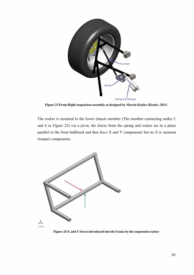
Figure 23 Front-Right suspension assembly as designed by Marcin Kiszko (Kiszko, 2011)
The rocker is mounted to the lower chassis member (The member connecting nodes 2
and 4 in Figure 22) via a pivot, the forces from the spring and rocker act in a plane
parallel to the front bulkhead and thus have X and Y components but no Z or moment
(torque) components.
Figure 24 X and Y forces introduced into the frame by the suspension rocker
7/27/2019 2011 REV SAE SpaceFrame Waterman
http://slidepdf.com/reader/full/2011-rev-sae-spaceframe-waterman 30/61
31
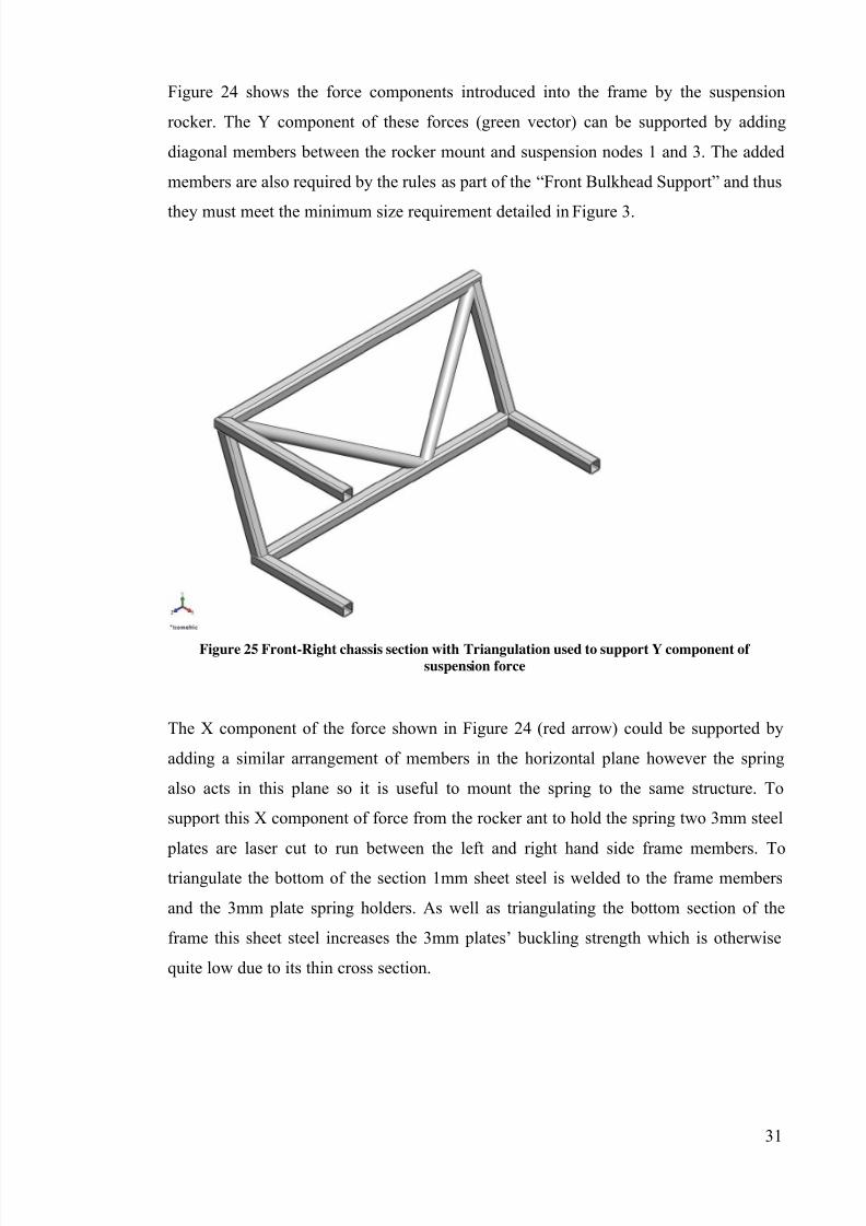
Figure 24 shows the force components introduced into the frame by the suspension
rocker. The Y component of these forces (green vector) can be supported by adding
diagonal members between the rocker mount and suspension nodes 1 and 3. The added
members are also required by the rules as part of the “Front Bulkhead Support” and thus
they must meet the minimum size requirement detailed in Figure 3.
Figure 25 Front-Right chassis section with Triangulation used to support Y component of suspension force
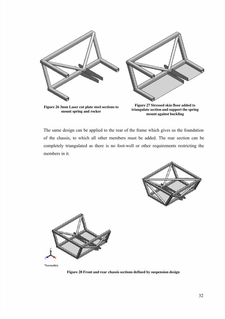
The X component of the force shown in Figure 24 (red arrow) could be supported by
adding a similar arrangement of members in the horizontal plane however the spring
also acts in this plane so it is useful to mount the spring to the same structure. To
support this X component of force from the rocker ant to hold the spring two 3mm steel
plates are laser cut to run between the left and right hand side frame members. To
triangulate the bottom of the section 1mm sheet steel is welded to the frame members
and the 3mm plate spring holders. As well as triangulating the bottom section of the
frame this sheet steel increases the 3mm plates’ buckling strength which is otherwise
quite low due to its thin cross section.
7/27/2019 2011 REV SAE SpaceFrame Waterman
http://slidepdf.com/reader/full/2011-rev-sae-spaceframe-waterman 31/61
32
Figure 27 Stressed skin floor added to
triangulate section and support the spring
mount against buckling
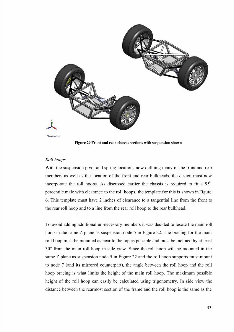
The same design can be applied to the rear of the frame which gives us the foundation
of the chassis, to which all other members must be added. The rear section can be
completely triangulated as there is no foot-well or other requirements restricting the
members in it.
Figure 28 Front and rear chassis sections defined by suspension design
Figure 26 3mm Laser cut plate steel sections to
mount spring and rocker
7/27/2019 2011 REV SAE SpaceFrame Waterman
http://slidepdf.com/reader/full/2011-rev-sae-spaceframe-waterman 32/61
33
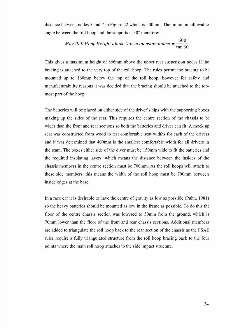
Figure 29 Front and rear chassis sections with suspension shown
Roll hoops
With the suspension pivot and spring locations now defining many of the front and rear
members as well as the location of the front and rear bulkheads, the design must now
incorporate the roll hoops. As discussed earlier the chassis is required to fit a 95 th
percentile male with clearance to the roll hoops, the template for this is shown in Figure
6. This template must have 2 inches of clearance to a tangential line from the front to
the rear roll hoop and to a line from the rear roll hoop to the rear bulkhead.
To avoid adding additional un-necessary members it was decided to locate the main roll
hoop in the same Z plane as suspension node 5 in Figure 22. The bracing for the main
roll hoop must be mounted as near to the top as possible and must be inclined by at least
30° from the main roll hoop in side view. Since the roll hoop will be mounted in the
same Z plane as suspension node 5 in Figure 22 and the roll hoop supports must mount
to node 7 (and its mirrored counterpart), the angle between the roll hoop and the roll
hoop bracing is what limits the height of the main roll hoop. The maximum possible
height of the roll hoop can easily be calculated using trigonometry. In side view the
distance between the rearmost section of the frame and the roll hoop is the same as the
7/27/2019 2011 REV SAE SpaceFrame Waterman
http://slidepdf.com/reader/full/2011-rev-sae-spaceframe-waterman 33/61
34
distance between nodes 5 and 7 in Figure 22 which is 500mm. The minimum allowable
angle between the roll hoop and the supports is 30° therefore:
ℎ =500
tan 30
This gives a maximum height of 866mm above the upper rear suspension nodes if the
bracing is attached to the very top of the roll hoop. The rules permit the bracing to be
mounted up to 160mm below the top of the roll hoop, however for safety and
manufacturability reasons it was decided that the bracing should be attached to the top-
most part of the hoop.
The batteries will be placed on either side of the driver’s hips with the supporting boxes
making up the sides of the seat. This requires the centre section of the chassis to be
wider than the front and rear sections so both the batteries and driver can fit. A mock up
seat was constructed from wood to test comfortable seat widths for each of the drivers
and it was determined that 400mm is the smallest comfortable width for all drivers in
the team. The boxes either side of the diver must be 150mm wide to fit the batteries and
the required insulating layers, which means the distance between the insides of the
chassis members in the centre section must be 700mm. As the roll hoops will attach to
these side members, this means the width of the roll hoop must be 700mm between
inside edges at the base.
In a race car it is desirable to have the centre of gravity as low as possible (Puhn, 1981)
so the heavy batteries should be mounted as low in the frame as possible. To do this the
floor of the centre chassis section was lowered to 50mm from the ground, which is
70mm lower than the floor of the front and rear chassis sections. Additional members
are added to triangulate the roll hoop back to the rear section of the chassis as the FSAE
rules require a fully triangulated structure from the roll hoop bracing back to the four
points where the main roll hoop attaches to the side impact structure.
7/27/2019 2011 REV SAE SpaceFrame Waterman
http://slidepdf.com/reader/full/2011-rev-sae-spaceframe-waterman 34/61
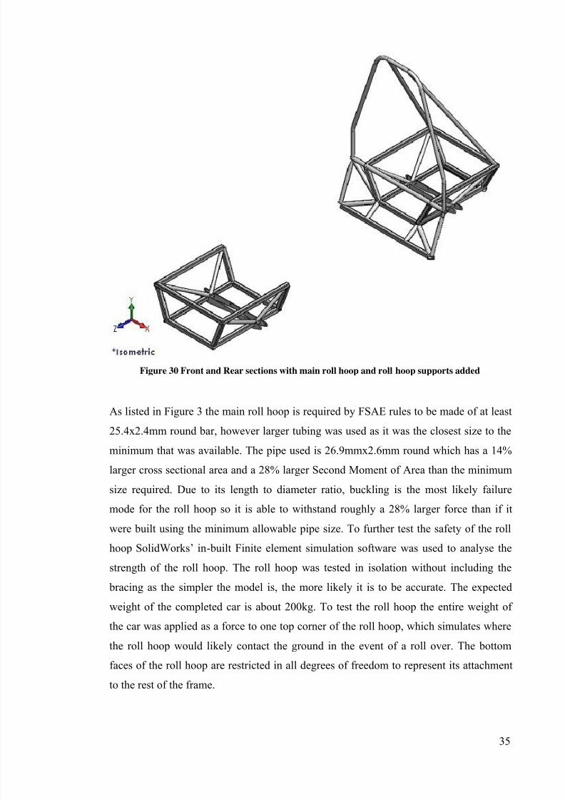
35
Figure 30 Front and Rear sections with main roll hoop and roll hoop supports added
As listed in Figure 3 the main roll hoop is required by FSAE rules to be made of at least
25.4x2.4mm round bar, however larger tubing was used as it was the closest size to the
minimum that was available. The pipe used is 26.9mmx2.6mm round which has a 14%
larger cross sectional area and a 28% larger Second Moment of Area than the minimum
size required. Due to its length to diameter ratio, buckling is the most likely failure
mode for the roll hoop so it is able to withstand roughly a 28% larger force than if it
were built using the minimum allowable pipe size. To further test the safety of the roll
hoop SolidWorks’ in-built Finite element simulation software was used to analyse the
strength of the roll hoop. The roll hoop was tested in isolation without including the
bracing as the simpler the model is, the more likely it is to be accurate. The expected
weight of the completed car is about 200kg. To test the roll hoop the entire weight of
the car was applied as a force to one top corner of the roll hoop, which simulates where
the roll hoop would likely contact the ground in the event of a roll over. The bottom
faces of the roll hoop are restricted in all degrees of freedom to represent its attachment
to the rest of the frame.
7/27/2019 2011 REV SAE SpaceFrame Waterman
http://slidepdf.com/reader/full/2011-rev-sae-spaceframe-waterman 35/61
36
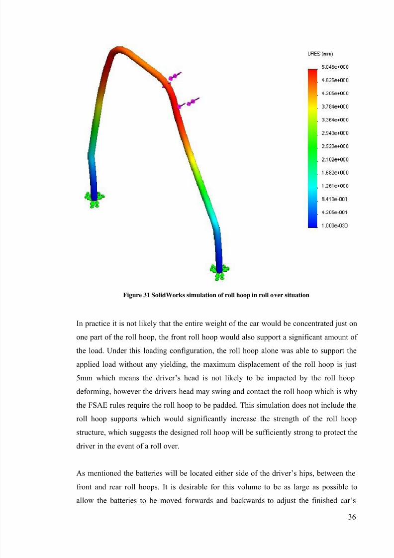
Figure 31 SolidWorks simulation of roll hoop in roll over situation
In practice it is not likely that the entire weight of the car would be concentrated just on
one part of the roll hoop, the front roll hoop would also support a significant amount of
the load. Under this loading configuration, the roll hoop alone was able to support the
applied load without any yielding, the maximum displacement of the roll hoop is just
5mm which means the driver’s head is not likely to be impacted by the roll hoop
deforming, however the drivers head may swing and contact the roll hoop which is why
the FSAE rules require the roll hoop to be padded. This simulation does not include the
roll hoop supports which would significantly increase the strength of the roll hoop
structure, which suggests the designed roll hoop will be sufficiently strong to protect the
driver in the event of a roll over.
As mentioned the batteries will be located either side of the driver’s hips, between the
front and rear roll hoops. It is desirable for this volume to be as large as possible toallow the batteries to be moved forwards and backwards to adjust the finished car’s
7/27/2019 2011 REV SAE SpaceFrame Waterman
http://slidepdf.com/reader/full/2011-rev-sae-spaceframe-waterman 36/61
37
centre of gravity. This can be used to alter the car’s handling characteristics which has
the potential to make the car faster (Puhn,1981). To keep the volume for the batteries
between the roll hoops as large as possible, the front roll hoop is angled rearwards from
vertical. Doing so maximises the distance between the bases of the roll hoops but keeps
the top of the front roll hoop in the desired position. The location of the front roll hoop’s
upper horizontal section governs the position of the steering wheel. According to the
FSAE rules the steering wheel must be no greater than 250mm from the front roll hoop.
The front roll hoop must therefore be leant rearwards so that the driver can comfortably
reach the steering wheel while in the seat.
Leaning the roll hoop in the rearward direction as such requires additional bracing be
added to the rear of the front roll hoop according to FSAE rules. Having additional bracing on either side of the driver has the potential to hinder the driver while getting in
and out of the cockpit. This is more than just an inconvenience for the driver as the
FSAE rules requires the driver be able to exit the cockpit in less than 5 seconds. If it is
difficult for the driver to exit the cockpit then this could also be a safety concern, in the
event of a fire, possibly caused by a failed battery for example, the driver could be
injured if he/she is not able to exit the car easily and quickly enough. In order to make it
as easy as possible for the driver to get over these required roll hoop supports they are
connected to the rear roll hoop where it meets the side impact structure. This makes it
easy for the driver to swing his/her legs over the lower rear part of this support while
holding their weight with their arms on the higher front part of the roll hoop support.
Side impact structure
The FSAE rules require a side impact structure to be present in the frame to protect the
driver in the event of a side-on collision. It consists of two horizontal members and one
diagonal member, the side impact structure connects the front and rear roll hoops. With
the car at its normal ride height with a 77kg driver seated in the driving position the
upper member must be 300mm to 350mm from the ground. This height corresponds to
the height of the upper chassis members in the front and rear sections so the upper side
impact member can simply connect these sections. There is no requirement for the
height of the lower side impact member so it can be placed at the desired height of
50mm above the ground. The diagonal side impact member simply runs between the
intersection of the front hoop and upper side impact member, and the intersection of the
7/27/2019 2011 REV SAE SpaceFrame Waterman
http://slidepdf.com/reader/full/2011-rev-sae-spaceframe-waterman 37/61
38
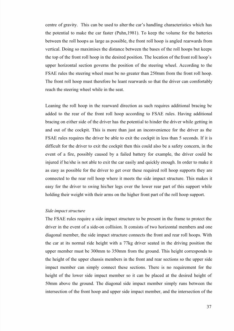
rear hoop and the lower side impact member. This diagonal also provides additional
support for the front roll hoop and triangulates the sides of the frame.
Figure 32 Front roll hoop, roll hoop supports and side impact structure now shown
.
Front Bulkhead and Foot-well
The FSAE Rules require supports that extend from the front roll hoop to the structure in
front of the drivers feet. In this chassis design that requires the forward hoop supportsconnect to the front bulkhead. The foot-well will have a raised floor to clear the
internally mounted front springs so the front bulkhead must be high enough so the
braces clear the foot-well template in Figure 5. The springs necessitate a floor that is
50mm above the height of the upper surface of the lower frame members in the front
section.
7/27/2019 2011 REV SAE SpaceFrame Waterman
http://slidepdf.com/reader/full/2011-rev-sae-spaceframe-waterman 38/61
39
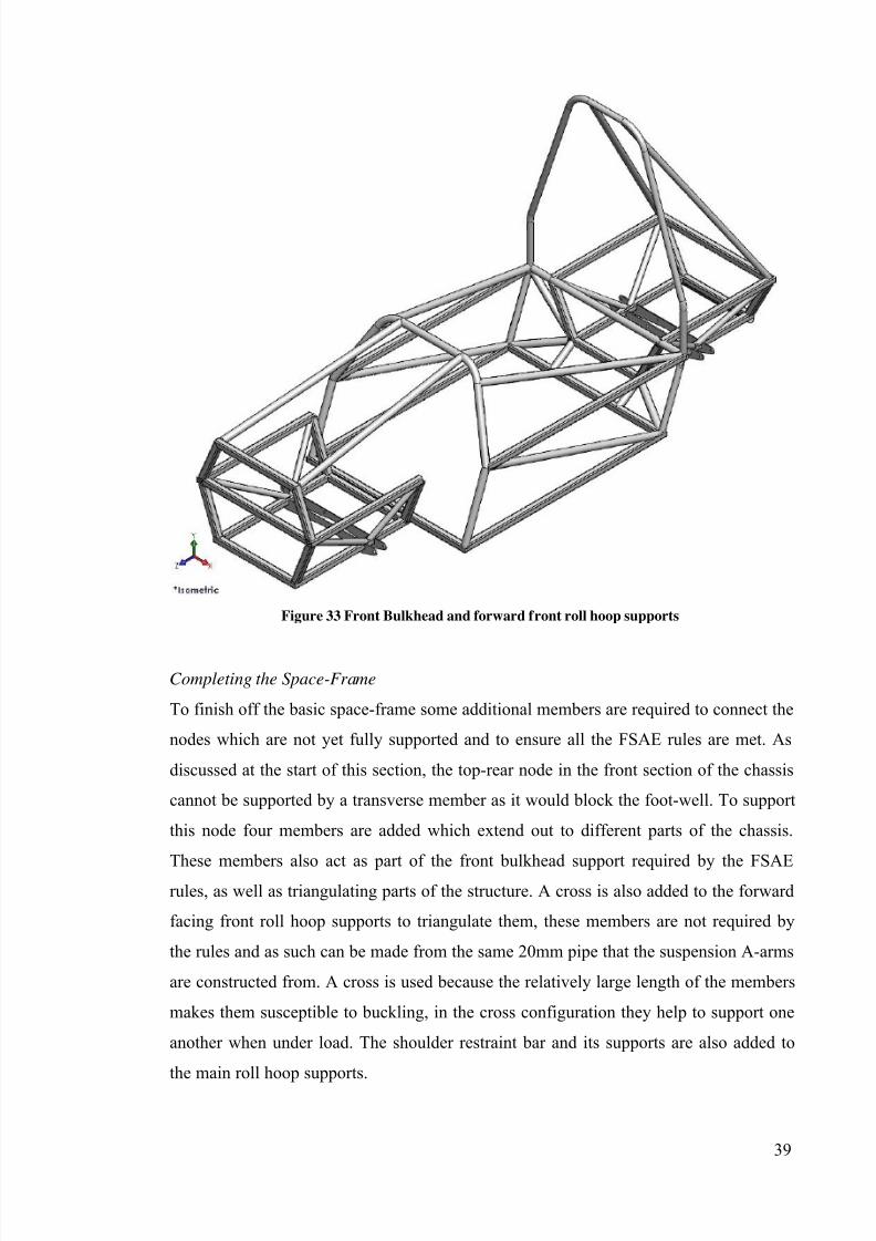
Figure 33 Front Bulkhead and forward front roll hoop supports
Completing the Space-Frame
To finish off the basic space-frame some additional members are required to connect the
nodes which are not yet fully supported and to ensure all the FSAE rules are met. As
discussed at the start of this section, the top-rear node in the front section of the chassis
cannot be supported by a transverse member as it would block the foot-well. To support
this node four members are added which extend out to different parts of the chassis.
These members also act as part of the front bulkhead support required by the FSAErules, as well as triangulating parts of the structure. A cross is also added to the forward
facing front roll hoop supports to triangulate them, these members are not required by
the rules and as such can be made from the same 20mm pipe that the suspension A-arms
are constructed from. A cross is used because the relatively large length of the members
makes them susceptible to buckling, in the cross configuration they help to support one
another when under load. The shoulder restraint bar and its supports are also added to
the main roll hoop supports.
7/27/2019 2011 REV SAE SpaceFrame Waterman
http://slidepdf.com/reader/full/2011-rev-sae-spaceframe-waterman 39/61
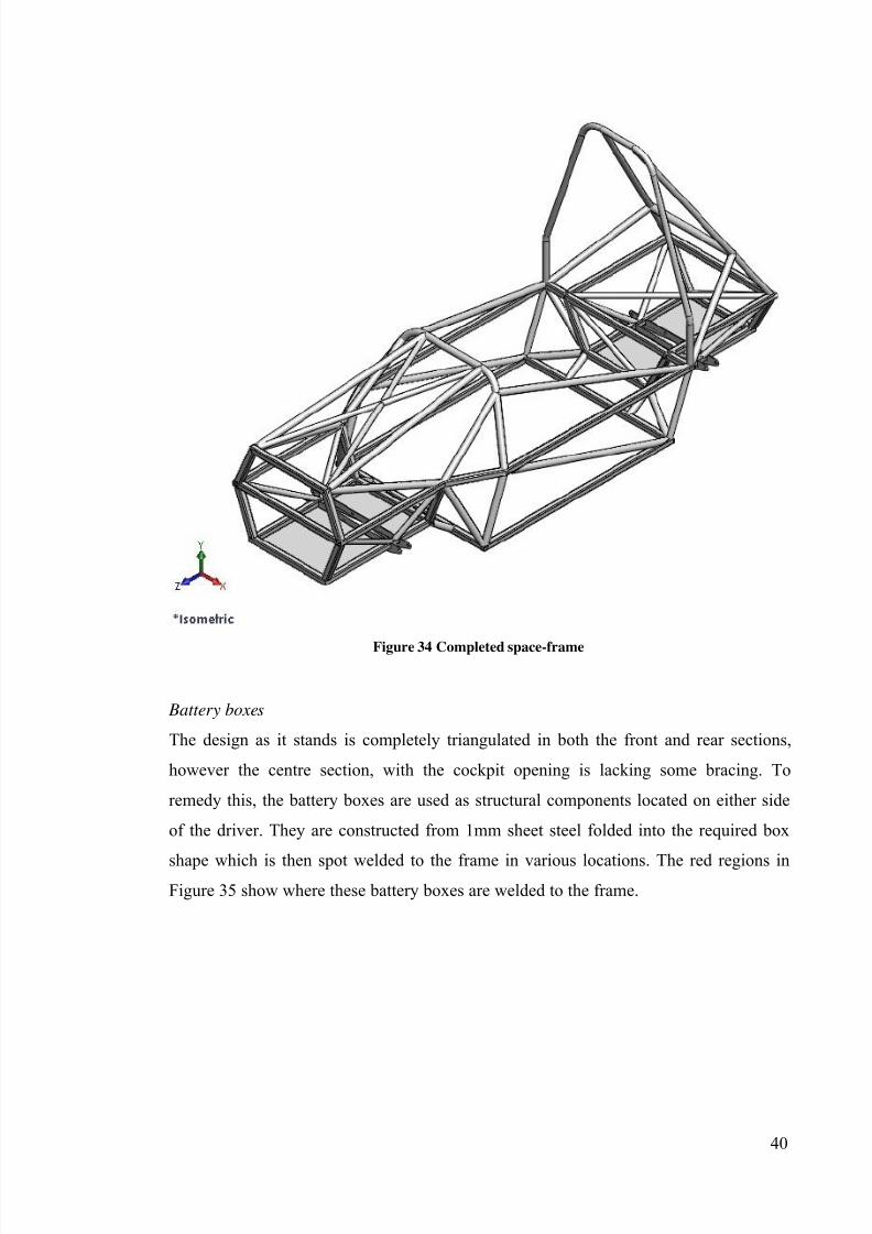
40
Figure 34 Completed space-frame
Battery boxes
The design as it stands is completely triangulated in both the front and rear sections,
however the centre section, with the cockpit opening is lacking some bracing. To
remedy this, the battery boxes are used as structural components located on either side
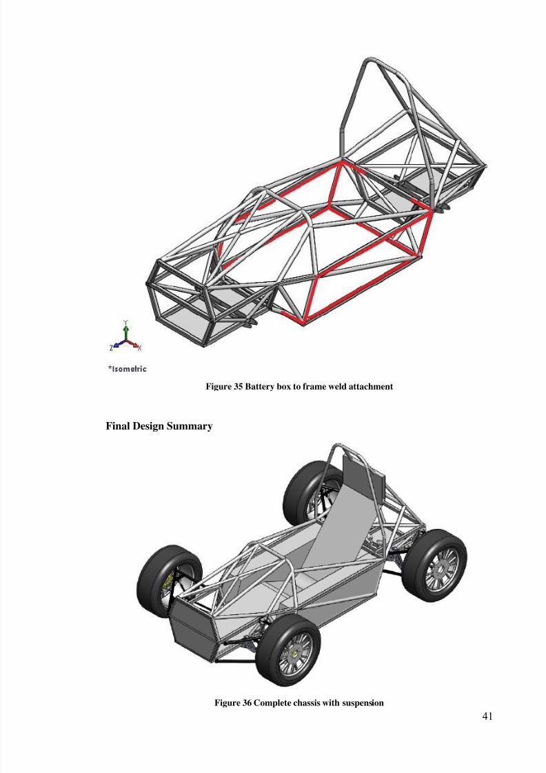
of the driver. They are constructed from 1mm sheet steel folded into the required box
shape which is then spot welded to the frame in various locations. The red regions inFigure 35 show where these battery boxes are welded to the frame.
7/27/2019 2011 REV SAE SpaceFrame Waterman
http://slidepdf.com/reader/full/2011-rev-sae-spaceframe-waterman 40/61
41
Figure 35 Battery box to frame weld attachment
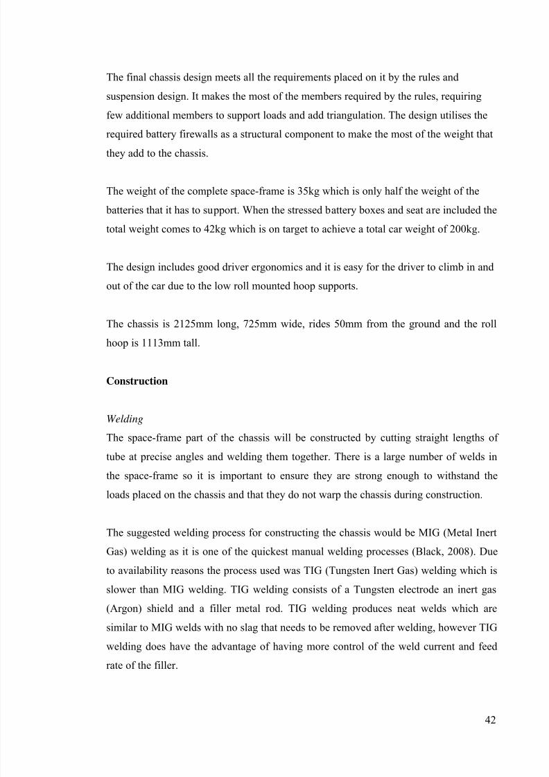
Final Design Summary
Figure 36 Complete chassis with suspension
7/27/2019 2011 REV SAE SpaceFrame Waterman
http://slidepdf.com/reader/full/2011-rev-sae-spaceframe-waterman 41/61
42
The final chassis design meets all the requirements placed on it by the rules and
suspension design. It makes the most of the members required by the rules, requiring
few additional members to support loads and add triangulation. The design utilises the
required battery firewalls as a structural component to make the most of the weight thatthey add to the chassis.
The weight of the complete space-frame is 35kg which is only half the weight of the
batteries that it has to support. When the stressed battery boxes and seat are included the
total weight comes to 42kg which is on target to achieve a total car weight of 200kg.
The design includes good driver ergonomics and it is easy for the driver to climb in andout of the car due to the low roll mounted hoop supports.
The chassis is 2125mm long, 725mm wide, rides 50mm from the ground and the roll
hoop is 1113mm tall.
Construction
Welding
The space-frame part of the chassis will be constructed by cutting straight lengths of
tube at precise angles and welding them together. There is a large number of welds in
the space-frame so it is important to ensure they are strong enough to withstand the
loads placed on the chassis and that they do not warp the chassis during construction.
The suggested welding process for constructing the chassis would be MIG (Metal Inert
Gas) welding as it is one of the quickest manual welding processes (Black, 2008). Due
to availability reasons the process used was TIG (Tungsten Inert Gas) welding which is
slower than MIG welding. TIG welding consists of a Tungsten electrode an inert gas
(Argon) shield and a filler metal rod. TIG welding produces neat welds which are
similar to MIG welds with no slag that needs to be removed after welding, however TIG
welding does have the advantage of having more control of the weld current and feed
rate of the filler.
7/27/2019 2011 REV SAE SpaceFrame Waterman
http://slidepdf.com/reader/full/2011-rev-sae-spaceframe-waterman 42/61
43
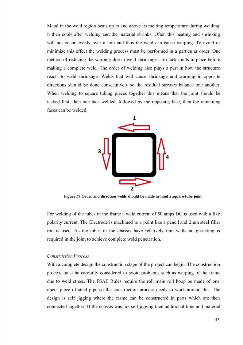
Metal in the weld region heats up to and above its melting temperature during welding,
it then cools after welding and the material shrinks. Often this heating and shrinking
will not occur evenly over a join and thus the weld can cause warping. To avoid or
minimize this effect the welding process must be performed in a particular order. One
method of reducing the warping due to weld shrinkage is to tack joints in place beforemaking a complete weld. The order of welding also plays a part in how the structure
reacts to weld shrinkage. Welds that will cause shrinkage and warping in opposite
directions should be done consecutively so the residual stresses balance one another.
When welding to square tubing pieces together this means that the joint should be
tacked first, then one face welded, followed by the opposing face, then the remaining
faces can be welded.
Figure 37 Order and direction welds should be made around a square tube joint
For welding of the tubes in the frame a weld current of 50 amps DC is used with a fixe
polarity current. The Electrode is machined to a point like a pencil and 2mm steel filler
rod is used. As the tubes in the chassis have relatively thin walls no gusseting is
required in the joint to achieve complete weld penetration.
Construction Process
With a complete design the construction stage of the project can begin. The construction
process must be carefully considered to avoid problems such as warping of the frame
due to weld stress. The FSAE Rules require the roll main roll hoop be made of one
uncut piece of steel pipe so the construction process needs to work around this. The
design is self jigging where the frame can be constructed in parts which are then
connected together. If the chassis was not self jigging then additional time and material

7/27/2019 2011 REV SAE SpaceFrame Waterman
http://slidepdf.com/reader/full/2011-rev-sae-spaceframe-waterman 43/61
44
would be used up making jigs to hold different members in place for welding. This
method is not viable for one off builds due to the time and materials that needs to be
invested into a jig, however if a number of the same chassis are being built then this
process can make construction faster after the jig is constructed. (Black, 2008)
The design of the space-frame includes four horizontal sections made from square tube
that can be constructed on a flat surface where they can be clamped down. As each of
these sections is in a single plane the cuts that make up the angled joints can be made
accurately with a mitre saw, meaning that the weld does not have to bridge a gap in the
joint due to poor cutting tolerances. With the members clamped to a flat surface they
can be welded together to form each rectangular section as well as the more complicated
top section.
Figure 38 Horizontal Planar sections are welded first
Once the flat horizontal sections are complete then they need to be joined together with
the vertical plane members. By using square tube for the horizontal sections these
upright members can also be cut simply with a mitre saw rather than requiring a “fish
mouth” joint which would be needed if round pipe was used for the horizontal sections.
7/27/2019 2011 REV SAE SpaceFrame Waterman
http://slidepdf.com/reader/full/2011-rev-sae-spaceframe-waterman 44/61
45
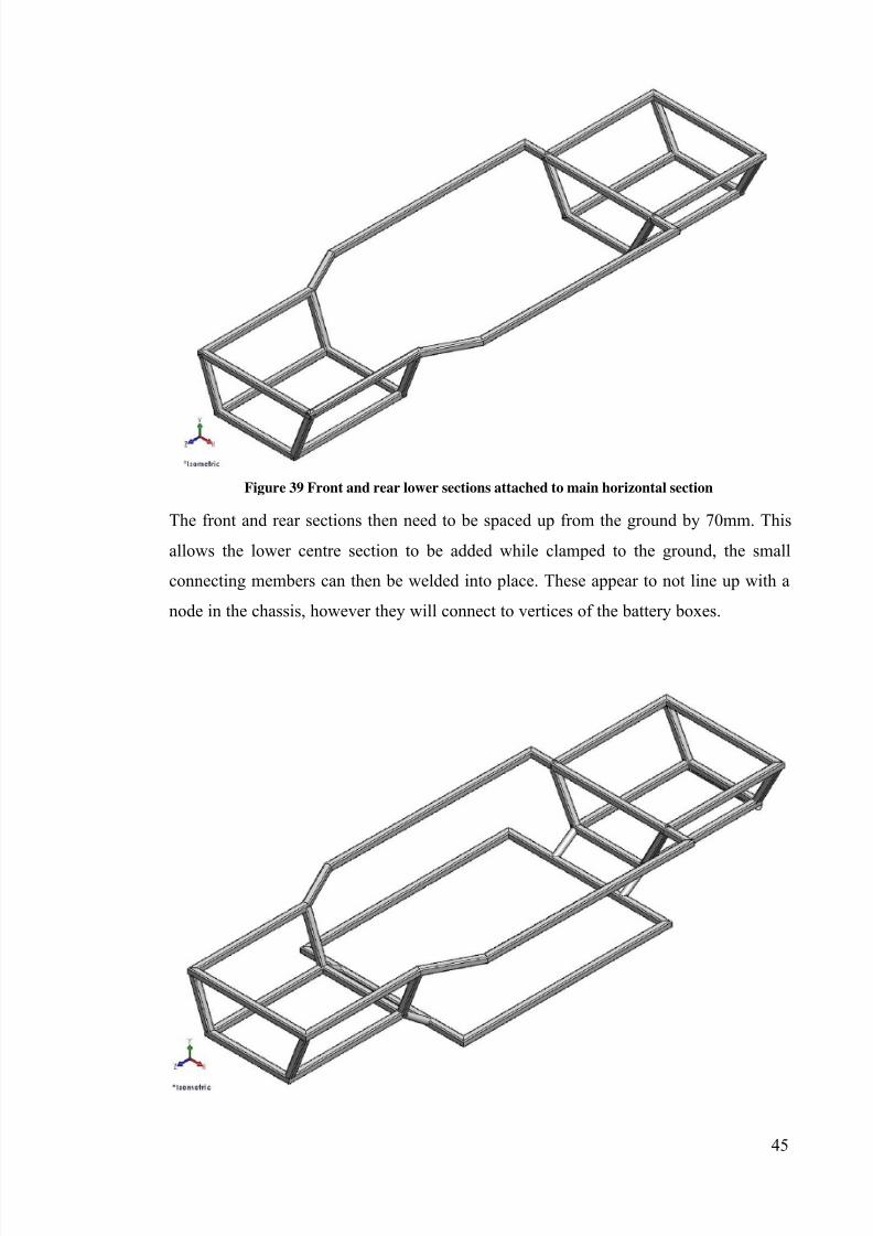
Figure 39 Front and rear lower sections attached to main horizontal section
The front and rear sections then need to be spaced up from the ground by 70mm. This
allows the lower centre section to be added while clamped to the ground, the small
connecting members can then be welded into place. These appear to not line up with a
node in the chassis, however they will connect to vertices of the battery boxes.
7/27/2019 2011 REV SAE SpaceFrame Waterman
http://slidepdf.com/reader/full/2011-rev-sae-spaceframe-waterman 45/61
46
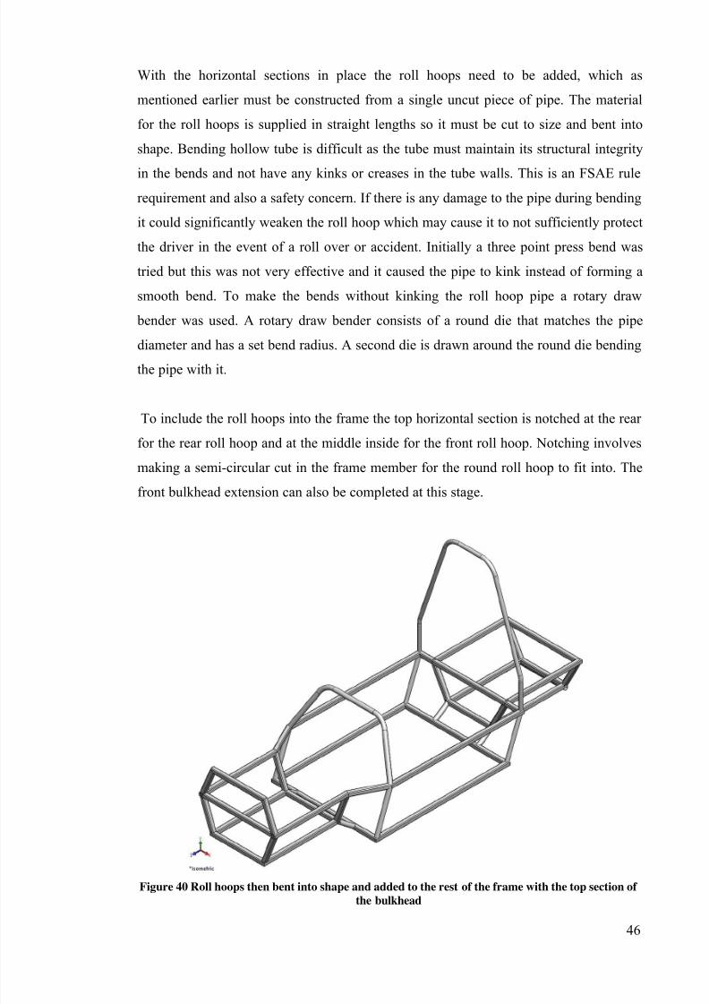
With the horizontal sections in place the roll hoops need to be added, which as
mentioned earlier must be constructed from a single uncut piece of pipe. The material
for the roll hoops is supplied in straight lengths so it must be cut to size and bent into
shape. Bending hollow tube is difficult as the tube must maintain its structural integrity
in the bends and not have any kinks or creases in the tube walls. This is an FSAE rulerequirement and also a safety concern. If there is any damage to the pipe during bending
it could significantly weaken the roll hoop which may cause it to not sufficiently protect
the driver in the event of a roll over or accident. Initially a three point press bend was
tried but this was not very effective and it caused the pipe to kink instead of forming a
smooth bend. To make the bends without kinking the roll hoop pipe a rotary draw
bender was used. A rotary draw bender consists of a round die that matches the pipe
diameter and has a set bend radius. A second die is drawn around the round die bendingthe pipe with it.
To include the roll hoops into the frame the top horizontal section is notched at the rear
for the rear roll hoop and at the middle inside for the front roll hoop. Notching involves
making a semi-circular cut in the frame member for the round roll hoop to fit into. The
front bulkhead extension can also be completed at this stage.
Figure 40 Roll hoops then bent into shape and added to the rest of the frame with the top section of
the bulkhead
7/27/2019 2011 REV SAE SpaceFrame Waterman
http://slidepdf.com/reader/full/2011-rev-sae-spaceframe-waterman 46/61
47
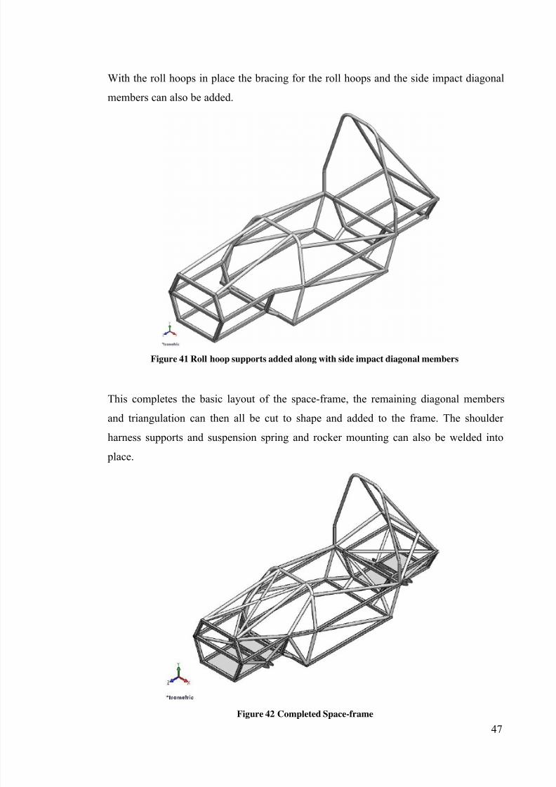
With the roll hoops in place the bracing for the roll hoops and the side impact diagonal
members can also be added.
Figure 41 Roll hoop supports added along with side impact diagonal members
This completes the basic layout of the space-frame, the remaining diagonal members
and triangulation can then all be cut to shape and added to the frame. The shoulder
harness supports and suspension spring and rocker mounting can also be welded into
place.
Figure 42 Completed Space-frame
7/27/2019 2011 REV SAE SpaceFrame Waterman
http://slidepdf.com/reader/full/2011-rev-sae-spaceframe-waterman 47/61
48
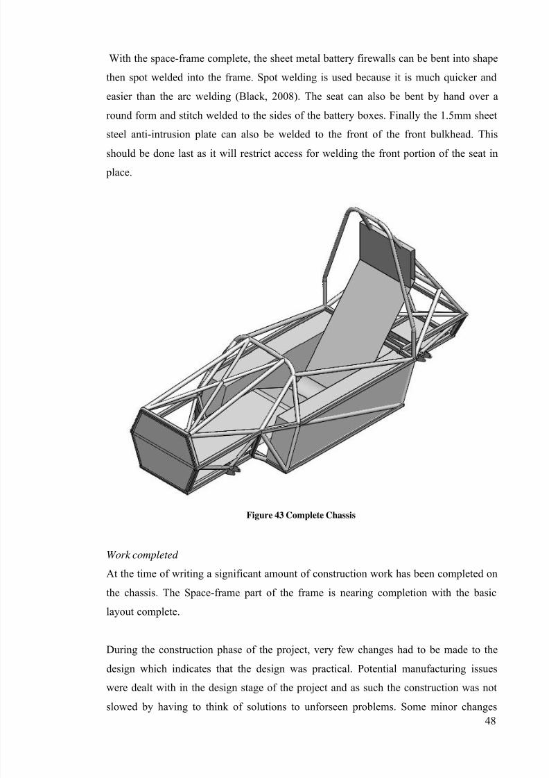
With the space-frame complete, the sheet metal battery firewalls can be bent into shape
then spot welded into the frame. Spot welding is used because it is much quicker and
easier than the arc welding (Black, 2008). The seat can also be bent by hand over a
round form and stitch welded to the sides of the battery boxes. Finally the 1.5mm sheet
steel anti-intrusion plate can also be welded to the front of the front bulkhead. Thisshould be done last as it will restrict access for welding the front portion of the seat in
place.
Figure 43 Complete Chassis
Work completed
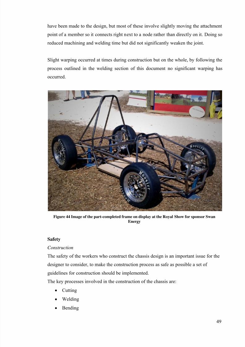
At the time of writing a significant amount of construction work has been completed on
the chassis. The Space-frame part of the frame is nearing completion with the basic
layout complete.
During the construction phase of the project, very few changes had to be made to the
design which indicates that the design was practical. Potential manufacturing issues
were dealt with in the design stage of the project and as such the construction was not
slowed by having to think of solutions to unforseen problems. Some minor changes
7/27/2019 2011 REV SAE SpaceFrame Waterman
http://slidepdf.com/reader/full/2011-rev-sae-spaceframe-waterman 48/61
49
have been made to the design, but most of these involve slightly moving the attachment
point of a member so it connects right next to a node rather than directly on it. Doing so
reduced machining and welding time but did not significantly weaken the joint.
Slight warping occurred at times during construction but on the whole, by following the process outlined in the welding section of this document no significant warping has
occurred.
Figure 44 Image of the part-completed frame on display at the Royal Show for sponsor Swan
Energy
Safety
Construction
The safety of the workers who construct the chassis design is an important issue for the
designer to consider, to make the construction process as safe as possible a set of
guidelines for construction should be implemented.
The key processes involved in the construction of the chassis are:
Cutting
Welding
Bending
7/27/2019 2011 REV SAE SpaceFrame Waterman
http://slidepdf.com/reader/full/2011-rev-sae-spaceframe-waterman 49/61
50
The construction of the chassis will take place in a workshop environment so closed
shoes should be worn by all people in the workshop at all times. Any person using tools
in the workshop should ensure that they do not have any loose clothing or jewellery
which may become tangled in machinery leading to serious injury or death.
As mentioned in previous sections much of the cutting can be done on a mitre saw due
to the use of square tubing. When cutting with an automated mitre band-saw several
safety precautions should be taken. The pipe should be securely clamped into the saw’s
holding clamps for cutting to ensure the piece does not get thrown out of the tool if the
blade catches on the work-piece. Safety glasses should be worn by anyone near the saw
while it is cutting to protect them from flying chips that may be thrown off the work-
piece. Before starting the saw, the operator should ensure that their own and others’hands and all other body parts are well clear of the saw to avoid being severely cut by
the blade. Where tubing is being cut to attach to a round member it needs to be cut with
a notching tool. This tool is like a hole saw but it is held in its own jig that also clamps
the work-piece in place. The same precautions as using the mitre band-saw should be
taken when using the notching tool.
Welding the joints in the chassis is potentially very hazardous work. Welding emits
very bright light including ultra-violet light, if care is not taken than people near the
welder may experience flash-burns to their retinas or even sunburn on their skin. To
prevent this welding should be done away from other workers and the welder must wear
clothing that covers all exposed skin. A welding mask must be worn when doing any
welding. Welding also makes the work-piece very hot (the weld region reaches the
metal’s melting temperature of ~1500°C (Callister, 2007)) so gloves made for welding
must be worn when handling any work-pieces that have been welded. Due to the mass
and cooling rate of the steel, a welded work-piece will stay hot for several minutes so to
ensure no person is burnt by handling a recently welded work-piece, hot parts should be
cooled in a designated area. If the hot work-piece cannot be isolated from all people in
the workshop then they should be informed that a particular part is hot and should not
be touched.
Bending the roll hoops is not as dangerous as cutting or welding but the process still
involves risk. The pipe bender applies significant amount of force to the work piece so
there is a hazard of crushing fingers in the bender, to avoid this, a check should be made
7/27/2019 2011 REV SAE SpaceFrame Waterman
http://slidepdf.com/reader/full/2011-rev-sae-spaceframe-waterman 50/61
51
before bending to ensure that the operator’s fingers are safely located on the bender’s
handle. The bender causes the work-piece to undergo significant strain and if there is
any coating (such as paint or rust) on the piece then this may chip and fly off, this could
potentially injure someone’s eyes so safety glasses should be worn when operating the
pipe bender.
Operation of the completed chassis
Once the construction of the chassis is complete then there is a risk of the chassis failing
in use which may injure the driver or bystanders. Failure of the chassis may involve a
weld breaking under normal operation which could lead to a part or complete loss of
control of the vehicle. In an effort to ensure this does not happen, the completed chassis
should be tested in a controlled environment before being used. The testing shouldstress the chassis in a similar way to how it is stressed in use and as such it should be
tested in torsion. Doing so will give a quantitative indication of how the chassis
performs by giving a measured value for the torsional stiffness in N/m. The testing
procedure will stress the frame and all the welded joints to a higher amount than they
would be in normal operation, if the chassis does not fail or yield in any way then the
chassis can be considered safe.
The chassis may also be involved in an accident, colliding with a barrier or rolling over,
it should be sufficiently strong to withstand the loads induced by the accident. The
FSAE rules for the minimum sizes of some chassis members are chosen such that the
chassis should be strong enough to survive these types of collisions. The chassis
designed in this project uses larger and stronger members than required by the FSAE
rules and also has more supports connected to the front bulkhead than required by the
FSAE rules. This means that the REV chassis will be much stronger in the event of a
front-on impact than the FSAE rules require. An impact attenuator is also required by
the FSAE rules to be mounted to the front bulkhead which dissipates some of the energy
of the impact and reduces the accelerations. As discussed the use of square tubing in the
side impact structure makes it much stronger than the minimum required by the FSAE
rules.
The location of the batteries and the lack of a tall petrol engine mean that the completed
car will have a very low centre of gravity, which means that it is highly unlikely the
vehicle will roll over given that it only competes on flat tarmac surfaces. The roll hoop
7/27/2019 2011 REV SAE SpaceFrame Waterman
http://slidepdf.com/reader/full/2011-rev-sae-spaceframe-waterman 51/61
52
used in this chassis design is also larger than the minimum required by the FSAE rules
and as such should be able to withstand a roll over if one were to occur. The design
section of this document also shows that the designed roll hoop can withstand the force
of a roll-over and should protect the driver. As shown in the weld testing section of this
document, if a weld is stressed to its yield point, it undergoes ductile failure rather than brittle fracture. Ductile yielding is much safer than brittle fracture as if a chassis joint
were to crack and fail in a brittle manner then the driver may be cut or impaled on the
sharp fracture.
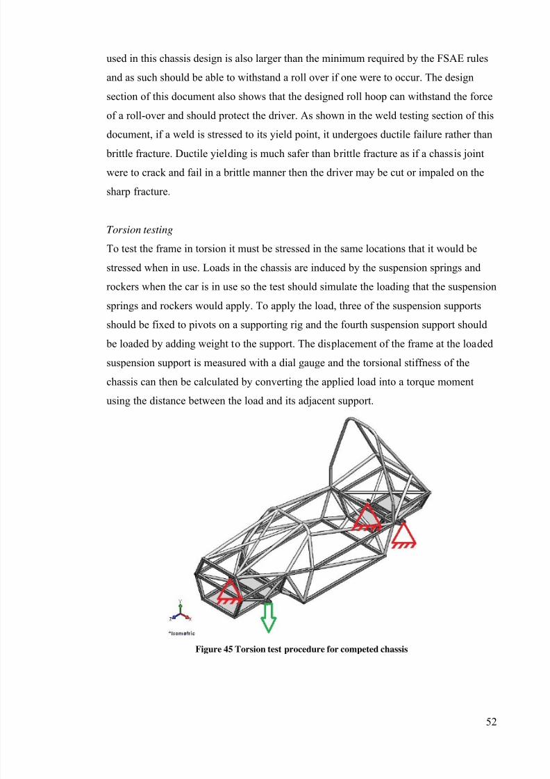
Torsion testing
To test the frame in torsion it must be stressed in the same locations that it would be
stressed when in use. Loads in the chassis are induced by the suspension springs androckers when the car is in use so the test should simulate the loading that the suspension
springs and rockers would apply. To apply the load, three of the suspension supports
should be fixed to pivots on a supporting rig and the fourth suspension support should
be loaded by adding weight to the support. The displacement of the frame at the loaded
suspension support is measured with a dial gauge and the torsional stiffness of the
chassis can then be calculated by converting the applied load into a torque moment
using the distance between the load and its adjacent support.
Figure 45 Torsion test procedure for competed chassis
7/27/2019 2011 REV SAE SpaceFrame Waterman
http://slidepdf.com/reader/full/2011-rev-sae-spaceframe-waterman 52/61
53
Weld Testing
To ensure the structural integrity of the completed space-frame will not be compromised
buy the welded joints it was decided that weld samples should be examined and tested.
The welds are located at the nodes and corners in the chassis and as such are the mosthighly stressed parts in the frame (see Triangulation and Stressed Skins section). If there
are any defects in the welds such as cracks, voids or porosity this could lead to failure of
the frame. A weld failure is a serious safety concern, the consequences of a weld failure
range from a decrease in frame stiffness to catastrophic failure of a safety component
such as the roll hoop which could lead to serious injury to the driver.
Visual inspection and destructive testing of a weld sample is the cheapest and easiestway to check the quality of the welds. It involves a very small amount of material and
very little time is needed to prepare the samples. To achieve the best indication of the
welds in the chassis, the weld samples were welded by the same person that completed
the welds in the chassis, using the same equipment and technique.
Two different samples were prepared and inspected, one wilt the square chassis tubing
welded to itself, the sample consisted of the square chassis tubing welded onto the roll
hoop tubing. Sample preparation for the square-square sample involved cutting a small
length of the same tubing used in the chassis to size. The tube sample was then cut in
half and the halves were then joined back together by welding. To inspect the welds a
cut was made through the weld perpendicular to the weld and the cut face was then
polished.
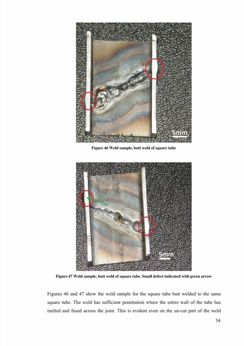
7/27/2019 2011 REV SAE SpaceFrame Waterman
http://slidepdf.com/reader/full/2011-rev-sae-spaceframe-waterman 53/61
54
Figure 46 Weld sample, butt weld of square tube
Figure 47 Weld sample, butt weld of square tube. Small defect indicated with green arrow
Figures 46 and 47 show the weld sample for the square tube butt welded to the same
square tube. The weld has sufficient penetration where the entire wall of the tube hasmelted and fused across the joint. This is evident even on the un-cut part of the weld
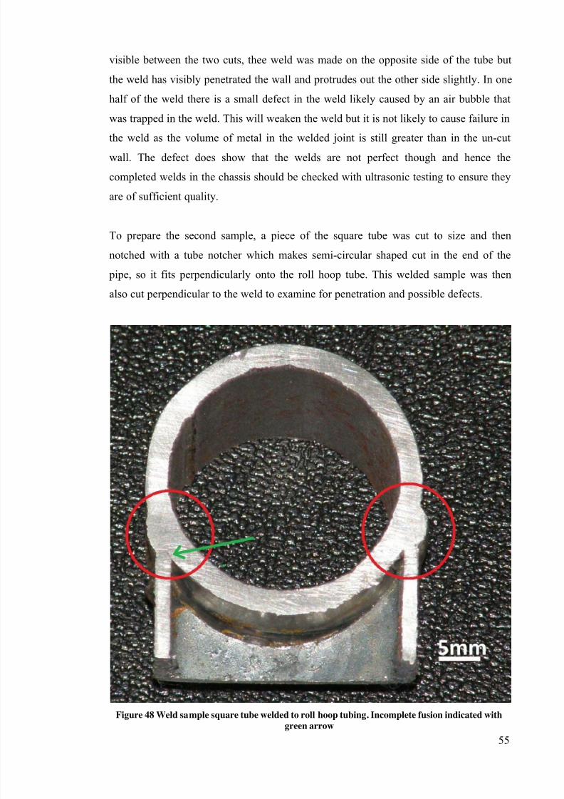
7/27/2019 2011 REV SAE SpaceFrame Waterman
http://slidepdf.com/reader/full/2011-rev-sae-spaceframe-waterman 54/61
55
visible between the two cuts, thee weld was made on the opposite side of the tube but
the weld has visibly penetrated the wall and protrudes out the other side slightly. In one
half of the weld there is a small defect in the weld likely caused by an air bubble that
was trapped in the weld. This will weaken the weld but it is not likely to cause failure in
the weld as the volume of metal in the welded joint is still greater than in the un-cutwall. The defect does show that the welds are not perfect though and hence the
completed welds in the chassis should be checked with ultrasonic testing to ensure they
are of sufficient quality.
To prepare the second sample, a piece of the square tube was cut to size and then
notched with a tube notcher which makes semi-circular shaped cut in the end of the
pipe, so it fits perpendicularly onto the roll hoop tube. This welded sample was thenalso cut perpendicular to the weld to examine for penetration and possible defects.
Figure 48 Weld sample square tube welded to roll hoop tubing. Incomplete fusion indicated with
green arrow
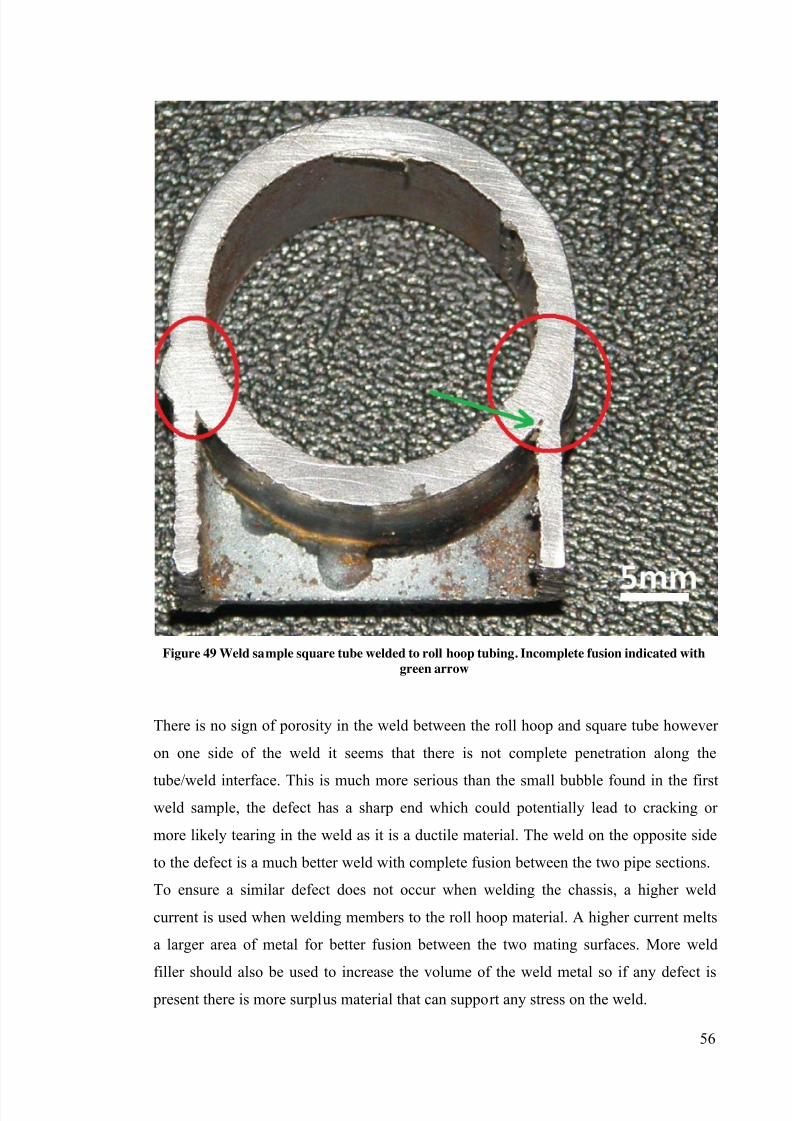
7/27/2019 2011 REV SAE SpaceFrame Waterman
http://slidepdf.com/reader/full/2011-rev-sae-spaceframe-waterman 55/61
56
Figure 49 Weld sample square tube welded to roll hoop tubing. Incomplete fusion indicated with
green arrow
There is no sign of porosity in the weld between the roll hoop and square tube however
on one side of the weld it seems that there is not complete penetration along the
tube/weld interface. This is much more serious than the small bubble found in the firstweld sample, the defect has a sharp end which could potentially lead to cracking or
more likely tearing in the weld as it is a ductile material. The weld on the opposite side
to the defect is a much better weld with complete fusion between the two pipe sections.
To ensure a similar defect does not occur when welding the chassis, a higher weld
current is used when welding members to the roll hoop material. A higher current melts
a larger area of metal for better fusion between the two mating surfaces. More weld
filler should also be used to increase the volume of the weld metal so if any defect is
present there is more surplus material that can support any stress on the weld.
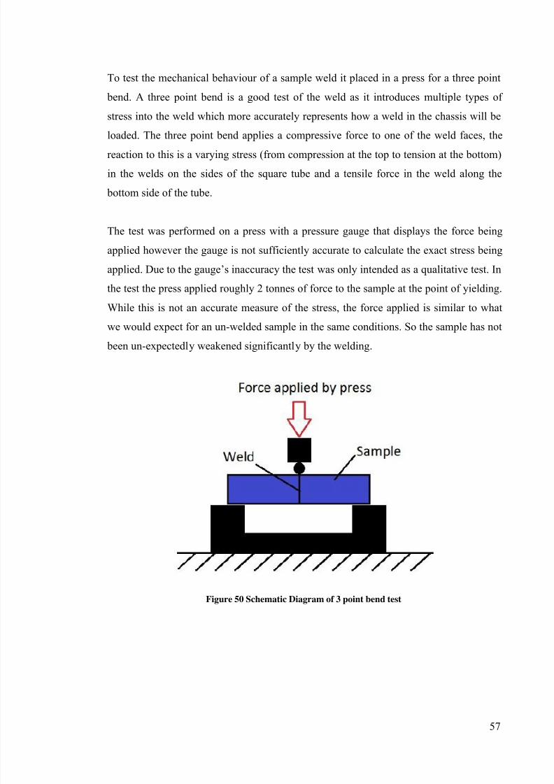
7/27/2019 2011 REV SAE SpaceFrame Waterman
http://slidepdf.com/reader/full/2011-rev-sae-spaceframe-waterman 56/61
57
To test the mechanical behaviour of a sample weld it placed in a press for a three point
bend. A three point bend is a good test of the weld as it introduces multiple types of
stress into the weld which more accurately represents how a weld in the chassis will be
loaded. The three point bend applies a compressive force to one of the weld faces, thereaction to this is a varying stress (from compression at the top to tension at the bottom)
in the welds on the sides of the square tube and a tensile force in the weld along the
bottom side of the tube.
The test was performed on a press with a pressure gauge that displays the force being
applied however the gauge is not sufficiently accurate to calculate the exact stress being
applied. Due to the gauge’s inaccuracy the test was only intended as a qualitative test. Inthe test the press applied roughly 2 tonnes of force to the sample at the point of yielding.
While this is not an accurate measure of the stress, the force applied is similar to what
we would expect for an un-welded sample in the same conditions. So the sample has not
been un-expectedly weakened significantly by the welding.
Figure 50 Schematic Diagram of 3 point bend test
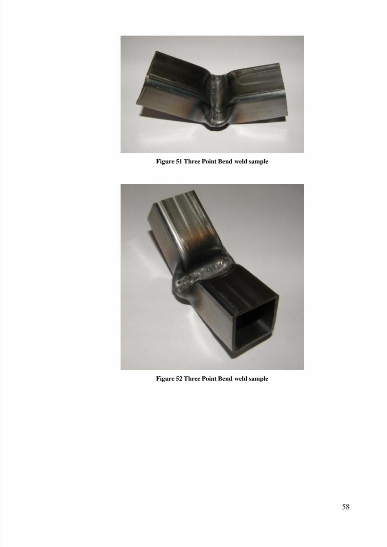
7/27/2019 2011 REV SAE SpaceFrame Waterman
http://slidepdf.com/reader/full/2011-rev-sae-spaceframe-waterman 57/61
58
Figure 51 Three Point Bend weld sample
Figure 52 Three Point Bend weld sample
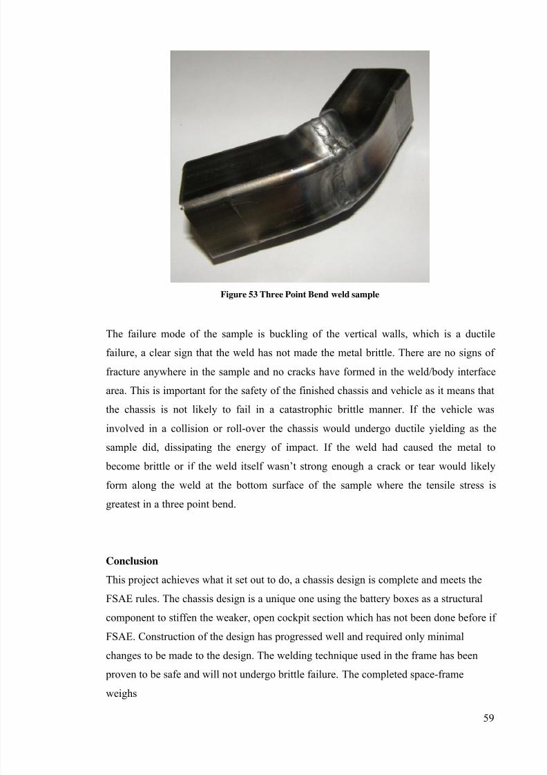
7/27/2019 2011 REV SAE SpaceFrame Waterman
http://slidepdf.com/reader/full/2011-rev-sae-spaceframe-waterman 58/61
59
Figure 53 Three Point Bend weld sample
The failure mode of the sample is buckling of the vertical walls, which is a ductile
failure, a clear sign that the weld has not made the metal brittle. There are no signs of
fracture anywhere in the sample and no cracks have formed in the weld/body interface
area. This is important for the safety of the finished chassis and vehicle as it means that
the chassis is not likely to fail in a catastrophic brittle manner. If the vehicle was
involved in a collision or roll-over the chassis would undergo ductile yielding as the
sample did, dissipating the energy of impact. If the weld had caused the metal to
become brittle or if the weld itself wasn’t strong enough a crack or tear would likely
form along the weld at the bottom surface of the sample where the tensile stress is
greatest in a three point bend.
Conclusion
This project achieves what it set out to do, a chassis design is complete and meets the
FSAE rules. The chassis design is a unique one using the battery boxes as a structural
component to stiffen the weaker, open cockpit section which has not been done before if
FSAE. Construction of the design has progressed well and required only minimal
changes to be made to the design. The welding technique used in the frame has been
proven to be safe and will not undergo brittle failure. The completed space-frameweighs
7/27/2019 2011 REV SAE SpaceFrame Waterman
http://slidepdf.com/reader/full/2011-rev-sae-spaceframe-waterman 59/61
60
Future work
Construction
At the time of writing, the majority of the space-frame construction has been completed.
Some triangulating members need to be added to the frame and the sheet metal battery boxes and seat need to be bent into shape and welded into the frame. These will be
completed by the end of 2011 however the car will no longer be entering the 2011
FSAE competition so the deadline is less strict now.
Chassis testing
The chassis testing mentioned in the safety section needs to be performed to measure
the chassis’ performance and to ensure it is safe. The torsional test will be performed onthe frame both before and after welding the battery boxes into place in order to get an
experimentally recorded value for the amount that they improve the stiffness of the
chassis in practice.
Ultrasonic weld testing
To further ensure the safety of the chassis and the quality of the welds the completed
frame should have the welds ultrasonically tested. This testing would have to be
outsourced to a third party but would provide a very accurate way of testing the welds
in the chassis itself. Testing of sample welds as mentioned is useful but does not
guarantee the quality of the welds in the frame, even though the welds were completed
by the same person with the same technique, many of the welds in the frame a in
awkward positions with limited access which may have reduced weld quality.
Ultrasonic weld testing can detect defects such as voids and cracks within the welds
(Black, 2008) which could weaken the structure. If any welds are found to have large
defects then they will be ground back and re-welded and re-tested.
Tuning
As the chassis will no longer be competing in the 2011 FSAE competition, there will be
another year for the chassis to be tested by driving this leaves enough time to make
changes to the chassis if necessary. It is unlikely that any significant changes will need
to be made to the chassis but things like moving the batteries forwards and backwards in
their boxes to adjust the car’s centre of gravity can be done to try and make the car as
quick as possible.
7/27/2019 2011 REV SAE SpaceFrame Waterman
http://slidepdf.com/reader/full/2011-rev-sae-spaceframe-waterman 60/61
61
Future designs
If the REV team decides to continue with using hub-motor powered electric cars then
the chassis designed in this project provides a good starting point for future designs.
Due to the nature of the rules, it is unlikely that it would be possible to significantlylighten the frame or significantly increase its torsional stiffness. Investigations into the
use of alternative materials may improve stiffness without increasing weight so this
would be an area worth investigating. This design uses sheet steel stressed-skin panels
in some areas, replacing these with carbon fibre composite panels would likely make the
sections stiffer and lighter, the same can be said for the battery boxes.
7/27/2019 2011 REV SAE SpaceFrame Waterman
http://slidepdf.com/reader/full/2011-rev-sae-spaceframe-waterman 61/61
References
(Adams, 1992)
Adams, H 1992, Chassis Engineering, Penguin Group, New York
(Aird, 1998)
Aird, F 1998, The Race Car Chassis, Penguin Group, New York
(Black,2008)
Black, J.T.& Kohser, R.A, 2008, Materials and Processes in Manufacturing, 10th
edn. John Wiley &
Sons Inc, United States of America
(Budynas,2011)
Budynas, R.G, Nisbett, J.K 2011, Shigley's Mechanical Engineering Design, 9th
edn. McGraw Hill, New
York
(Callister, 2007)
Callister, W & Rethwisch, D 2007, Materials Science and Engineering: An Introduction, 7th edn. John
Wiley & Sons Inc. United States of America.
(Kiszko, 2011)
Kiszko, M 2011, REV Formula SAE Electric – Suspension Design, School of Mechanical Engineering,
The University of Western Australia, Perth
(Puhn, 1981)
Puhn, F 1981, How to Make Your Car Handle, Penguin Group, New York
(SAE, 2010)
SAE International, 2010/2011 Formula SAE Rules, Available from:
<http://students.sae.org/competitions/formulaseries/rules/2011fsaerules.pdf>
(SAE, 2011)
SAE International, Addendum to Formula SAE Rules 2011, Available from:
<http://www.saea.com.au/wp-content/uploads/2010/11/FORMULA-SAE-A-Addendum-2011-V.2.pdf>
Other sources
University of Western Australia Motorsport (UWAM)


![Measuring the Traction Limits and Suspension Forces of a Formula SAE Racecar · [6] who experimentally determine the torsional rigidity of an FSAE spaceframe. Together, this previous](https://static.fdocuments.us/doc/165x107/60cc46f425dd701d9f04757c/measuring-the-traction-limits-and-suspension-forces-of-a-formula-sae-racecar-6.jpg)
