2009 roma, corso ablation frontiers nell'ablazione della fibrillazione atriale
45
Ablation Frontiers System
-
Upload
centro-diagnostico-nardi -
Category
Health & Medicine
-
view
103 -
download
0
Transcript of 2009 roma, corso ablation frontiers nell'ablazione della fibrillazione atriale

Ablation Frontiers System
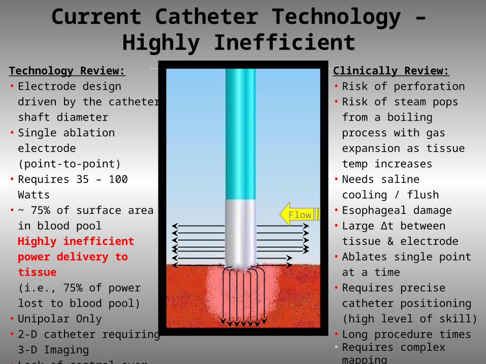
Technology Review:• Electrode design driven by
the catheter shaft diameter• Single ablation electrode
(point-to-point)• Requires 35 – 100 Watts• ~ 75% of surface area in
blood pool
Highly inefficient power
delivery to tissue
(i.e., 75% of power lost to
blood pool)• Unipolar Only• 2-D catheter requiring 3-D
Imaging• Lack of control over lesion
creation and catheter
placement
Current Catheter Technology – Highly Inefficient
Clinically Review:• Risk of perforation• Risk of steam pops from a
boiling process with gas
expansion as tissue temp
increases• Needs saline cooling / flush• Esophageal damage• Large Δt between tissue &
electrode• Ablates single point at a time• Requires precise catheter
positioning
(high level of skill)• Long procedure times• Requires complex mapping
Flow
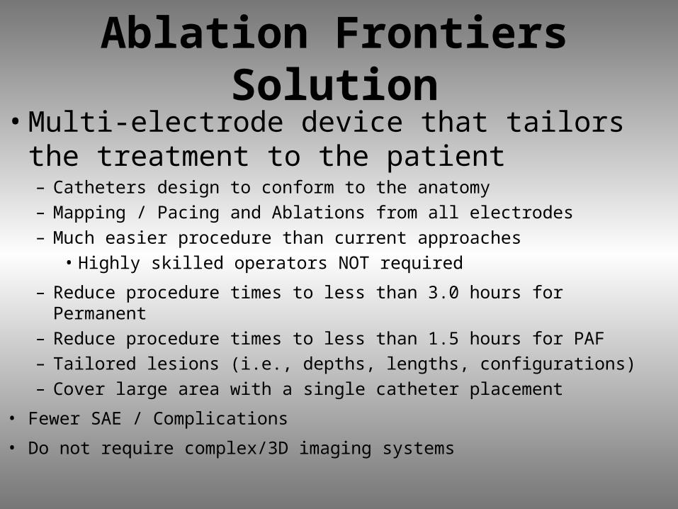
Ablation Frontiers Solution
• Multi-electrode device that tailors the treatment to the patient– Catheters design to conform to the anatomy– Mapping / Pacing and Ablations from all electrodes– Much easier procedure than current approaches
• Highly skilled operators NOT required
– Reduce procedure times to less than 3.0 hours for Permanent– Reduce procedure times to less than 1.5 hours for PAF– Tailored lesions (i.e., depths, lengths, configurations)– Cover large area with a single catheter placement
• Fewer SAE / Complications
• Do not require complex/3D imaging systems
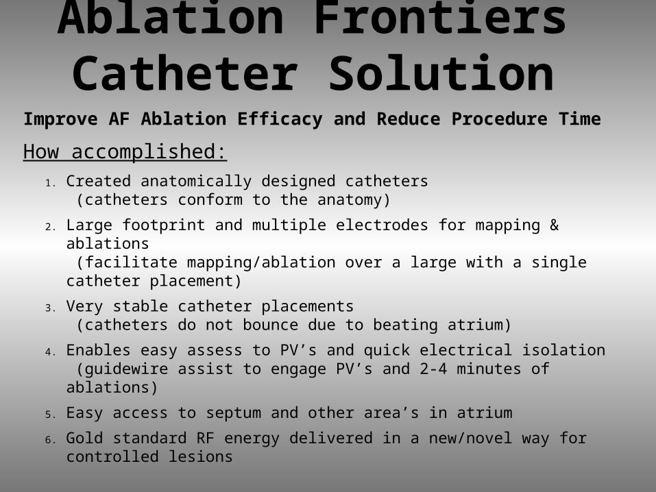
Ablation Frontiers Catheter Solution
Improve AF Ablation Efficacy and Reduce Procedure Time
How accomplished:1. Created anatomically designed catheters
(catheters conform to the anatomy)
2. Large footprint and multiple electrodes for mapping & ablations (facilitate mapping/ablation over a large with a single catheter placement)
3. Very stable catheter placements (catheters do not bounce due to beating atrium)
4. Enables easy assess to PV’s and quick electrical isolation (guidewire assist to engage PV’s and 2-4 minutes of ablations)
5. Easy access to septum and other area’s in atrium
6. Gold standard RF energy delivered in a new/novel way for controlled lesions
Ablation Frontiers RF Generator Solution
• RF Generator Features:
– Automated temperature control / power limited
– RF energy (bipolar / unipolar)• Maximize operator control of lesion size, shape,
depth
• Maximize power delivered efficiency to each catheter electrode or electrode pair
– Remote control capability
– Interfaces with existing electrogram recording systems e.g. EP Lab and Prucka System
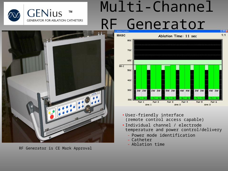
™ Multi-Channel RF Generator
• User-friendly interface (remote control access capable)
• Individual channel / electrode temperature and power control/delivery- Power mode identification- Catheter - Ablation timeRF Generator is CE Mark Approval
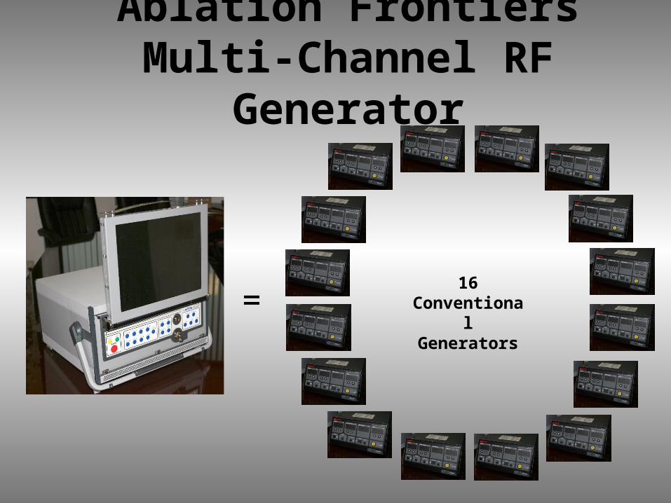
=16
ConventionalGenerators
Ablation Frontiers Multi-Channel RF Generator
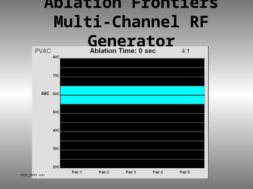
Ablation Frontiers Multi-Channel RF Generator
PVAC_RUN1.m4v
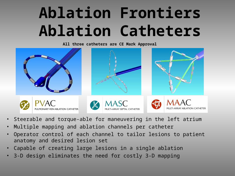
Ablation Frontiers Ablation Catheters
• Steerable and torque-able for maneuvering in the left atrium• Multiple mapping and ablation channels per catheter• Operator control of each channel to tailor lesions to patient anatomy and
desired lesion set• Capable of creating large lesions in a single ablation• 3-D design eliminates the need for costly 3-D mapping
All three catheters are CE Mark Approval
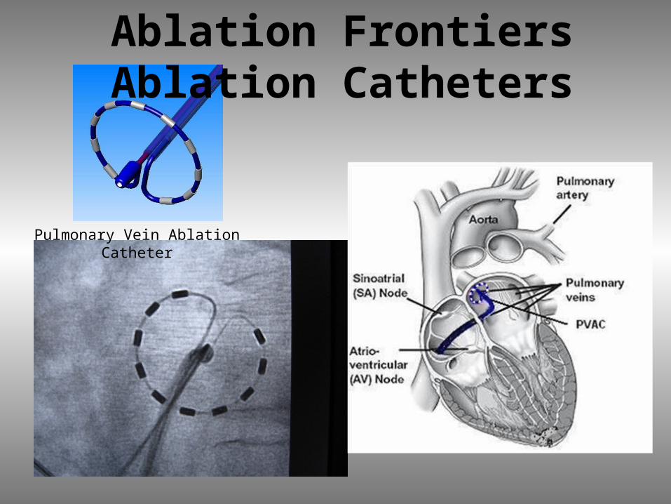
Pulmonary Vein Ablation Catheter
Ablation Frontiers Ablation Catheters
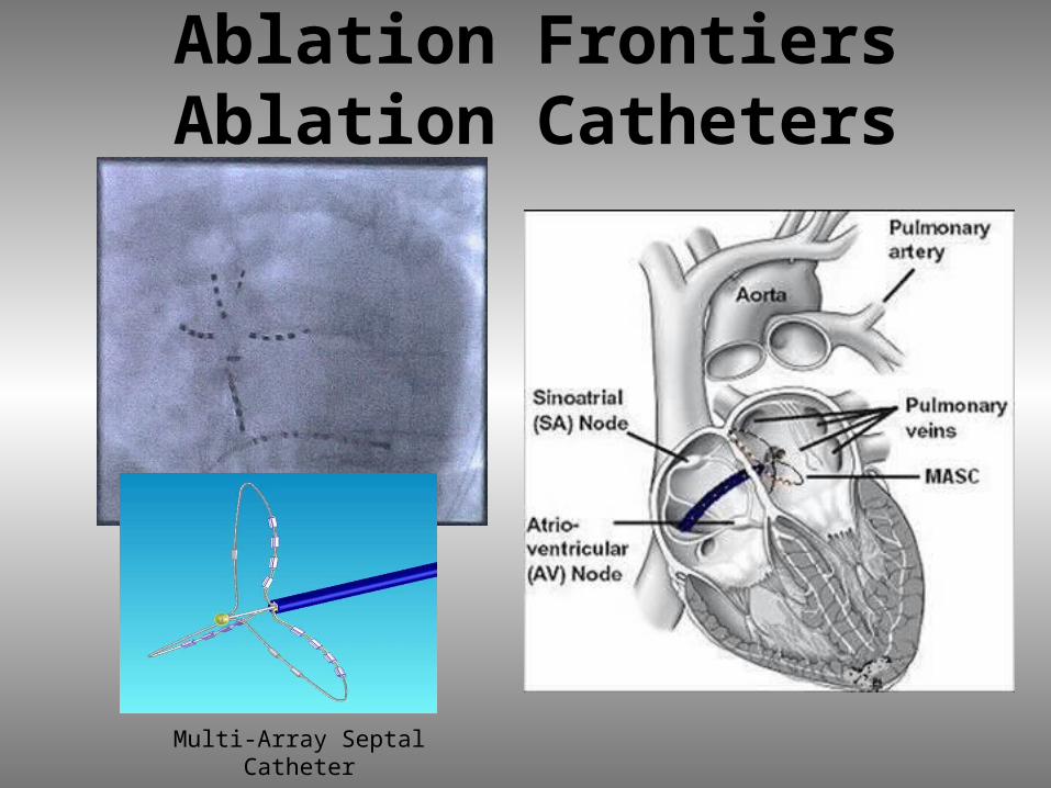
Multi-Array Septal Catheter
Ablation Frontiers Ablation Catheters

Multi-Array Ablation Catheter
Ablation Frontiers Ablation Catheters
How Does It Work Clinically?
• Anatomically Designed Catheters
• Selectable Energy Delivery
• Tailored Lesion Depth & Length
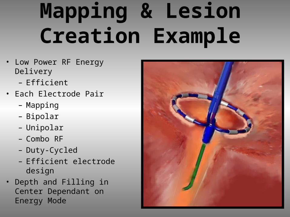
Mapping & Lesion Creation Example
• Low Power RF Energy Delivery– Efficient
• Each Electrode Pair– Mapping– Bipolar– Unipolar– Combo RF– Duty-Cycled– Efficient electrode design
• Depth and Filling in Center Dependant on Energy Mode
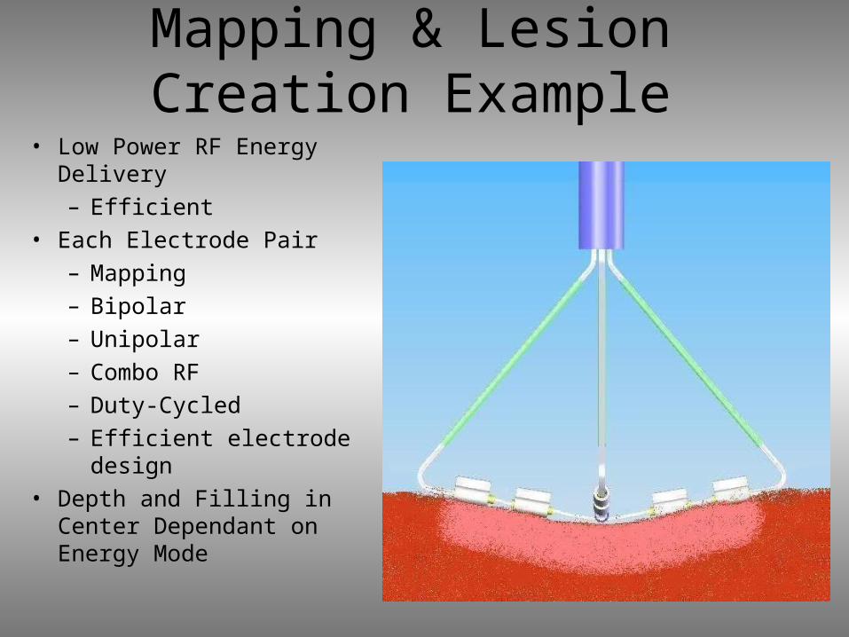
Mapping & Lesion Creation Example
• Low Power RF Energy Delivery– Efficient
• Each Electrode Pair– Mapping– Bipolar– Unipolar– Combo RF– Duty-Cycled– Efficient electrode
design• Depth and Filling in
Center Dependant on Energy Mode
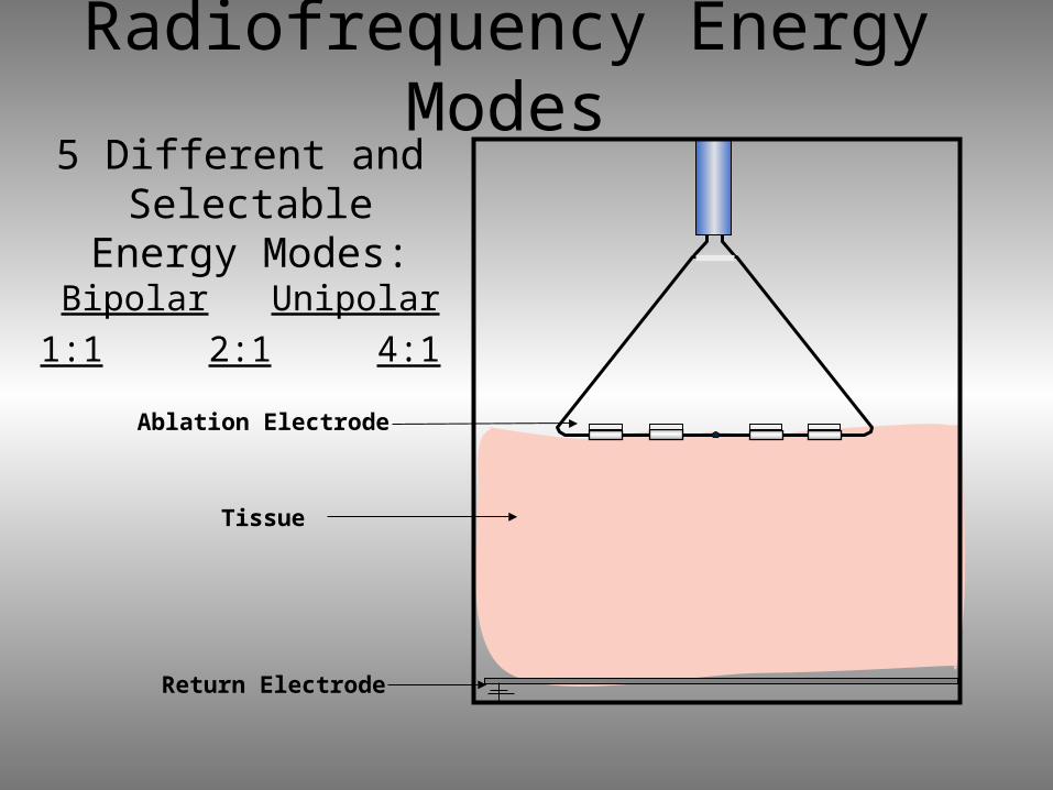
Radiofrequency Energy Modes5 Different and
Selectable Energy Modes:
Bipolar Unipolar1:1 2:1 4:1
Ablation Electrode
Tissue
Return Electrode
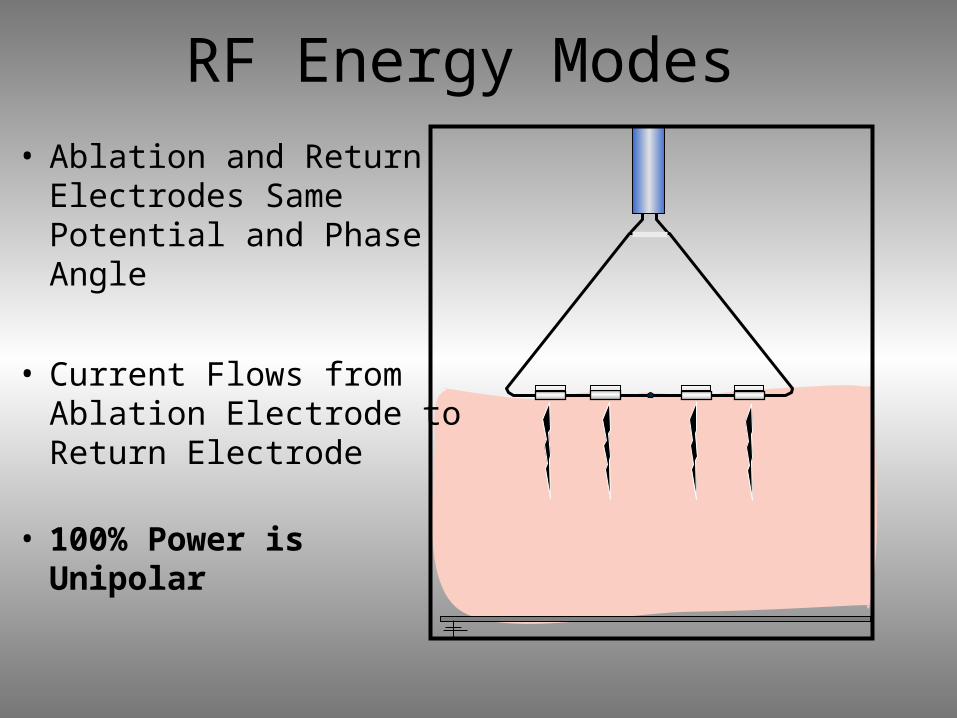
RF Energy Modes• Ablation and Return
Electrodes Same Potential and Phase Angle
• Current Flows from Ablation Electrode to Return Electrode
• 100% Power is Unipolar
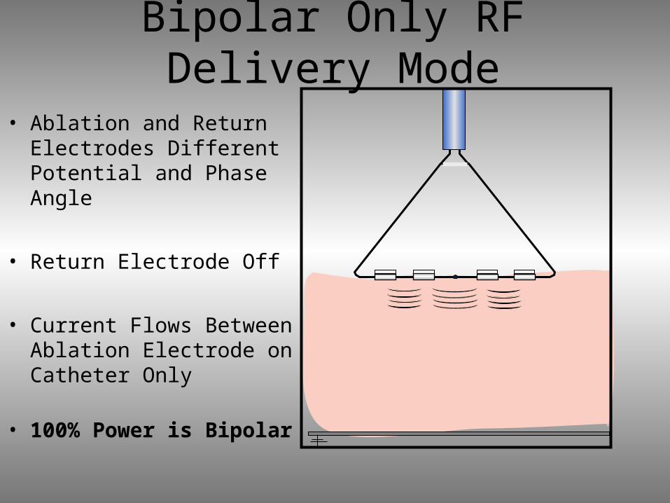
Bipolar Only RF Delivery Mode
• Ablation and Return Electrodes Different Potential and Phase Angle
• Return Electrode Off
• Current Flows Between Ablation Electrode on Catheter Only
• 100% Power is Bipolar
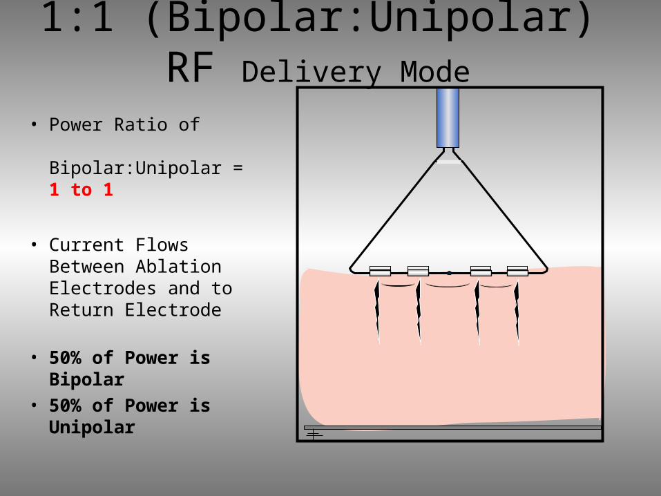
1:1 (Bipolar:Unipolar) RF Delivery Mode
• Power Ratio of Bipolar:Unipolar = 1 to 1
• Current Flows Between Ablation Electrodes and to Return Electrode
• 50% of Power is Bipolar
• 50% of Power is Unipolar
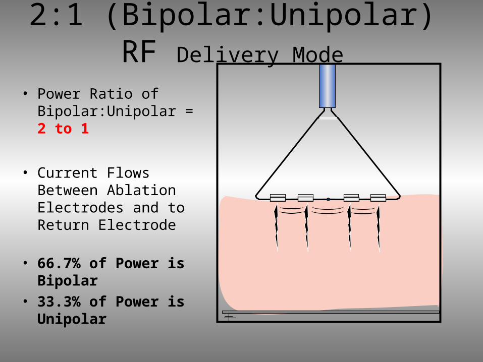
2:1 (Bipolar:Unipolar) RF Delivery Mode
• Power Ratio of Bipolar:Unipolar = 2 to 1
• Current Flows Between Ablation Electrodes and to Return Electrode
• 66.7% of Power is Bipolar
• 33.3% of Power is Unipolar
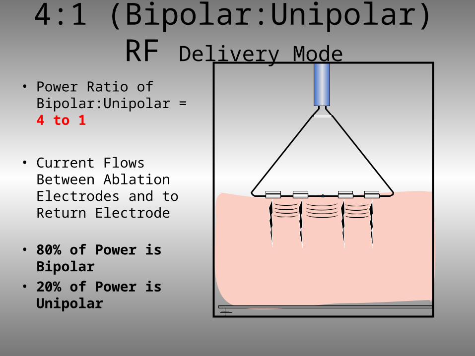
4:1 (Bipolar:Unipolar) RF Delivery Mode
• Power Ratio of Bipolar:Unipolar = 4 to 1
• Current Flows Between Ablation Electrodes and to Return Electrode
• 80% of Power is Bipolar
• 20% of Power is Unipolar
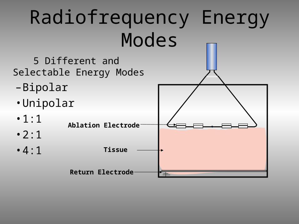
Radiofrequency Energy Modes
5 Different and Selectable Energy Modes
– Bipolar•Unipolar•1:1•2:1•4:1
Ablation Electrode
Tissue
Return Electrode
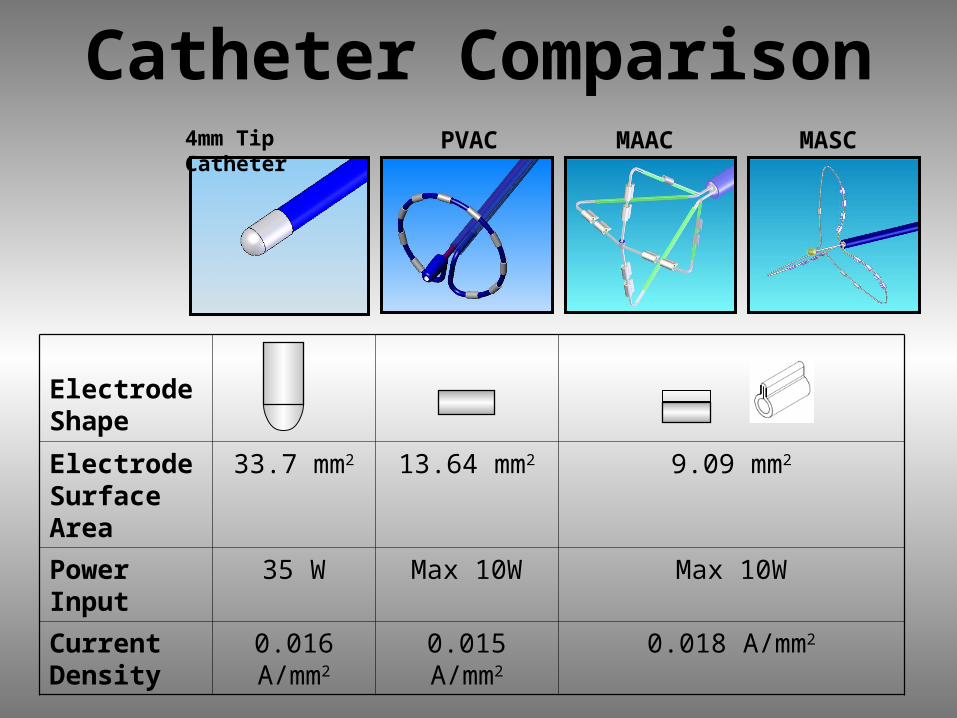
Catheter Comparison4mm Tip Catheter
PVAC
MAAC
MASC
Electrode Shape
Electrode Surface Area
33.7 mm2 13.64 mm2 9.09 mm2
Power Input
35 W Max 10W Max 10W
Current Density
0.016 A/mm2
0.015 A/mm2
0.018 A/mm2
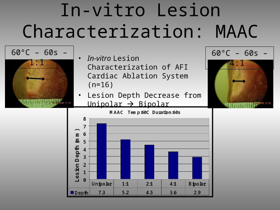
In-vitro Lesion Characterization: MAAC
• In-vitro Lesion Characterization of AFI Cardiac Ablation System (n=16)
• Lesion Depth Decrease from Unipolar Bipolar
60°C – 60s – 1:1
60°C – 60s – 4:1
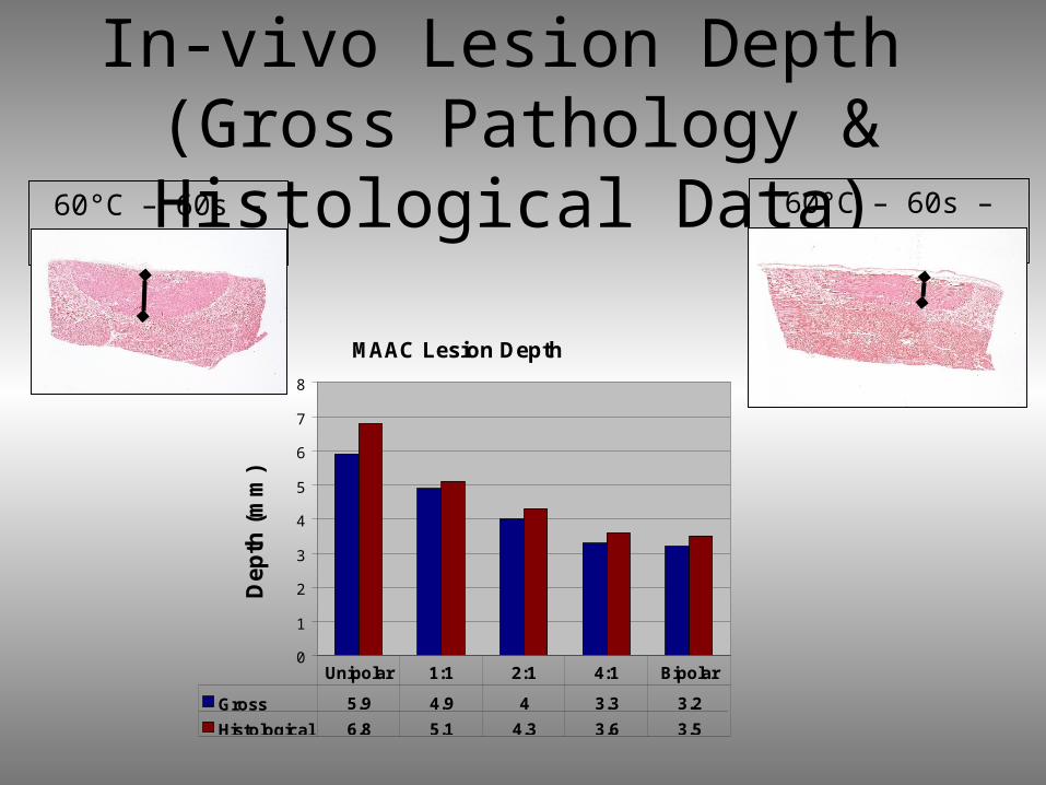
In-vivo Lesion Depth (Gross Pathology & Histological Data)60°C – 60s –
1:1 60°C – 60s – 4:1
MAAC Lesion Depth
0
1
2
3
4
5
6
7
8
Dep
th (
mm
)
Gross 5.9 4.9 4 3.3 3.2
Histological 6.8 5.1 4.3 3.6 3.5
Unipolar 1:1 2:1 4:1 Bipolar
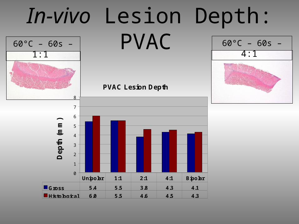
In-vivo Lesion Depth: PVAC60°C – 60s –
1:1 60°C – 60s – 4:1
PVAC Lesion Depth
0
1
2
3
4
5
6
7
8
Dep
th (
mm
)
Gross 5.4 5.5 3.8 4.3 4.1
Histological 6.0 5.5 4.6 4.5 4.3
Unipolar 1:1 2:1 4:1 Bipolar
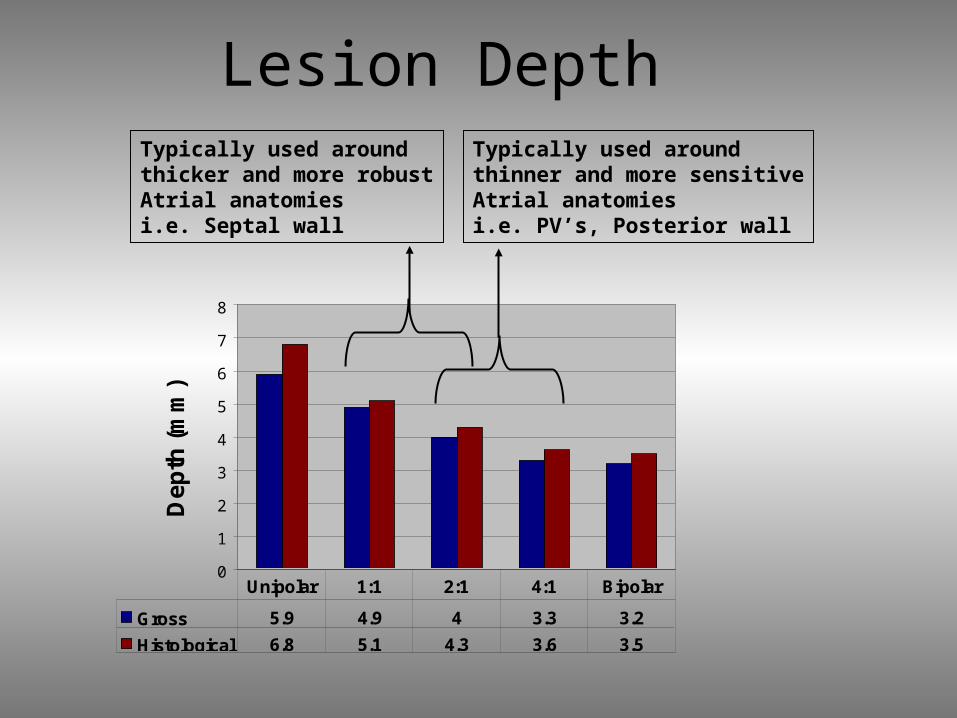
Lesion Depth
0
1
2
3
4
5
6
7
8
De
pth
(m
m)
Gross 5.9 4.9 4 3.3 3.2
Histological 6.8 5.1 4.3 3.6 3.5
Unipolar 1:1 2:1 4:1 Bipolar
Typically used around thicker and more robustAtrial anatomiesi.e. Septal wall
Typically used around thinner and more sensitiveAtrial anatomiesi.e. PV’s, Posterior wall

in-vivo Tissue Temperature60°C – 60s – 1:1 60°C – 60s – 4:1
Thermocouples placed at 2mm in depth under electrodes and between electrodes
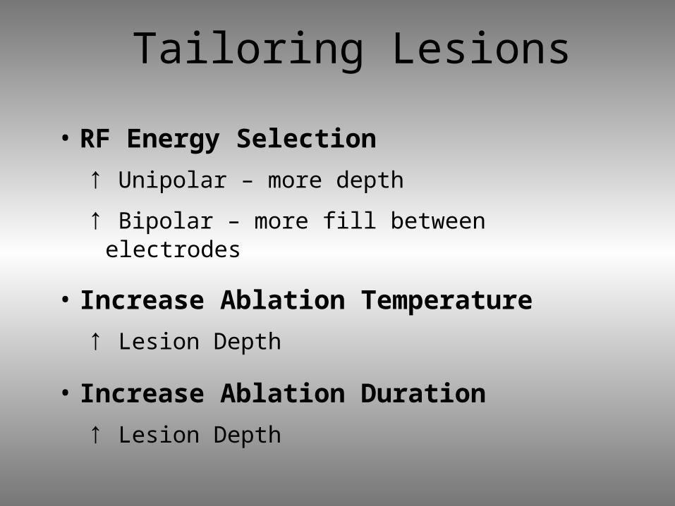
Tailoring Lesions
• RF Energy Selection
↑ Unipolar – more depth
↑ Bipolar – more fill between electrodes
• Increase Ablation Temperature
↑ Lesion Depth
• Increase Ablation Duration
↑ Lesion Depth
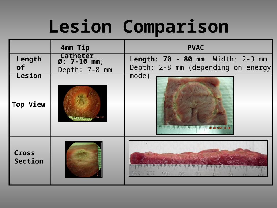
Lesion Comparison4mm Tip Catheter
PVAC
Top View
Cross Section
Length of Lesion
Ø: 7-10 mm; Depth: 7-8 mm
Length: 70 - 80 mm Width: 2-3 mm Depth: 2-8 mm (depending on energy mode)
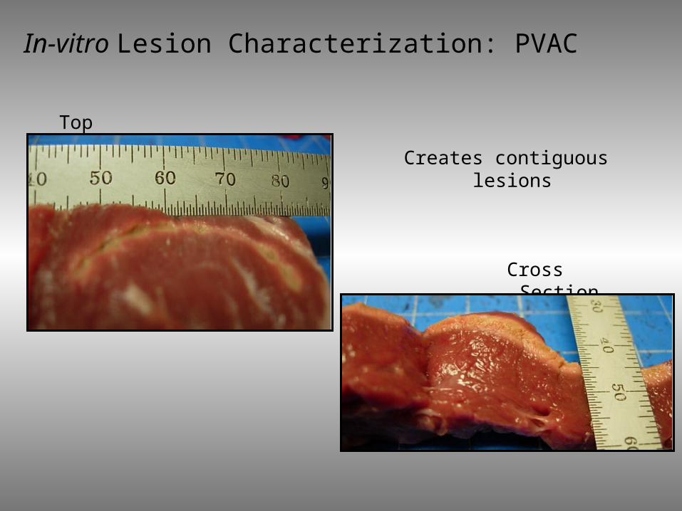
In-vitro Lesion Characterization: PVAC
Creates contiguous lesions
Cross Section
Top
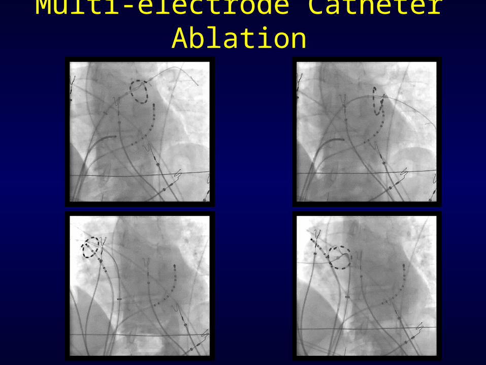
Multi-electrode Catheter Ablation

Atrial Fibrillation ablationAtrial Fibrillation ablationVagal GangliaVagal Ganglia

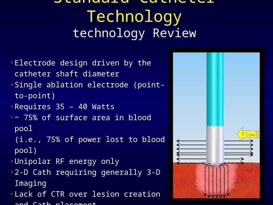
•Electrode design driven by the catheter shaft diameter
•Single ablation electrode (point-to-point)
•Requires 35 – 40 Watts •~ 75% of surface area in blood pool
(i.e., 75% of power lost to blood pool)•Unipolar RF energy only•2-D Cath requiring generally 3-D
Imaging•Lack of CTR over lesion creation and
Cath placement
Standard Catheter Technologytechnology Review
Flow
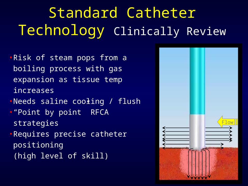
Standard Catheter Technology Clinically Review
•Risk of steam pops from a boiling process with gas expansion as tissue temp increases
•Needs saline cooling / flush•“Point by point” RFCA strategies•Requires precise catheter positioning (high level of skill)
Flow
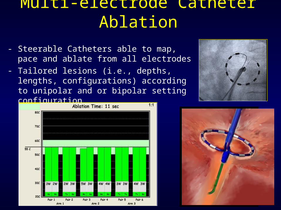
Multi-electrode Catheter Ablation
- Steerable Catheters able to map, pace and ablate from all electrodes
- Tailored lesions (i.e., depths, lengths, configurations) according to unipolar and or bipolar setting configuration
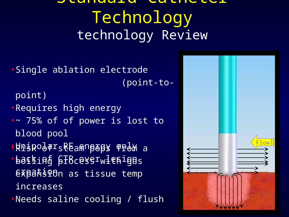
•Single ablation electrode (point-to-point)
•Requires high energy •~ 75% of of power is lost to blood pool
•Unipolar RF energy only•Lack of CTR over lesion creation
Standard Catheter Technologytechnology Review
Flow•Risk of steam pops from a boiling process with gas expansion as tissue temp increases
•Needs saline cooling / flush
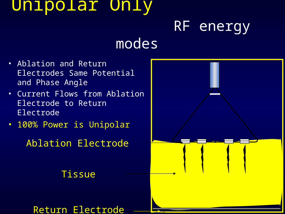
• Ablation and Return Electrodes Same Potential and Phase Angle
• Current Flows from Ablation Electrode to Return Electrode
• 100% Power is Unipolar
Unipolar Only RF energy modes
Ablation Electrode
Tissue
Return Electrode
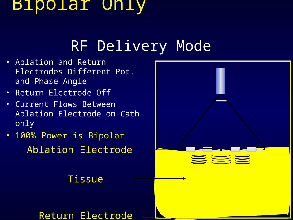
Bipolar Only RF Delivery Mode
• Ablation and Return Electrodes Different Pot. and Phase Angle
• Return Electrode Off• Current Flows Between
Ablation Electrode on Cath only
• 100% Power is Bipolar
Ablation Electrode
Tissue
Return Electrode
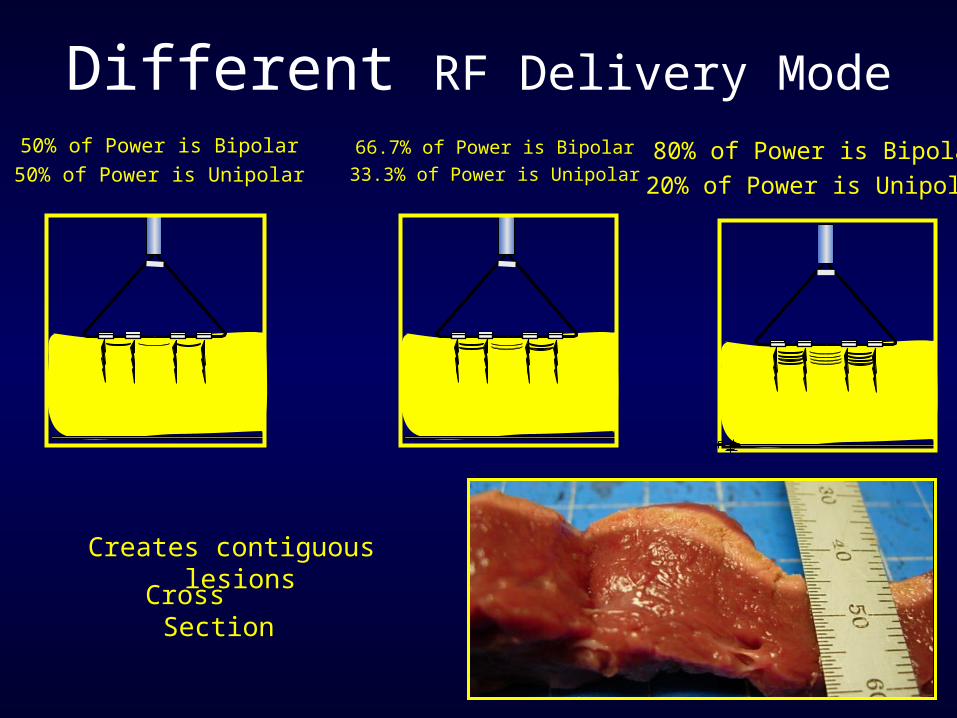
50% of Power is Bipolar50% of Power is Unipolar
66.7% of Power is Bipolar33.3% of Power is Unipolar
80% of Power is Bipolar20% of Power is Unipolar
Different RF Delivery Mode
Creates contiguous lesions
Cross Section
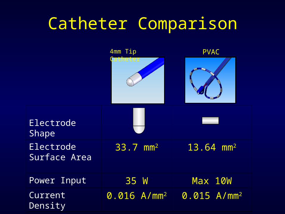
Catheter Comparison
4mm Tip Catheter
PVAC
Electrode Shape
Electrode Surface Area
33.7 mm2 13.64 mm2
Power Input 35 W Max 10WCurrent Density 0.016 A/mm2 0.015 A/mm2
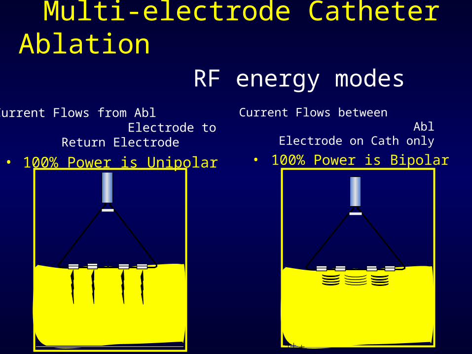
Multi-electrode Catheter Ablation RF
energy modesCurrent Flows from Abl
Electrode to Return Electrode
• 100% Power is Unipolar
Current Flows between Abl Electrode on Cath only
• 100% Power is Bipolar
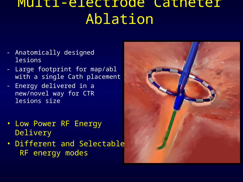
Multi-electrode Catheter Ablation
- Anatomically designed lesions - Large footprint for map/abl with
a single Cath placement- Energy delivered in a new/novel
way for CTR lesions size
• Low Power RF Energy Delivery
• Different and Selectable RF energy modes
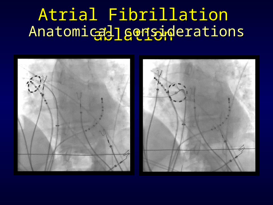
Atrial Fibrillation ablationAtrial Fibrillation ablationAnatomical considerationsAnatomical considerations