2004 Florida Building Code Plumbing / Fuel Gas Version 1.0 / June 2004 – 4 hour version Florida...
125
2004 Florida Building Code Plumbing / Fuel Gas Version 1.0 / June 2004 – 4 hour version Florida Building Commission Department of Community Affairs, Codes and Standards 2555 Shumard Oak Boulevard Tallahassee, FL 32399-2100 (850) 487-1824 http://www.floridabuilding.org
-
Upload
kyree-letson -
Category
Documents
-
view
221 -
download
1
Transcript of 2004 Florida Building Code Plumbing / Fuel Gas Version 1.0 / June 2004 – 4 hour version Florida...
2004 Florida Building Code
Plumbing / Fuel GasVersion 1.0 / June 2004 – 4 hour version
Florida Building CommissionDepartment of Community Affairs, Codes and
Standards2555 Shumard Oak BoulevardTallahassee, FL 32399-2100
(850) 487-1824http://www.floridabuilding.org

CHAPTER 1
ADMINISTRATION No significant changes

CHAPTER 1
ADMINISTRATION Refers to Chapter 1 of the Florida
Building Code, Building for administration and enforcement of the Florida Building Code, Plumbing.

CHAPTER 2
DEFINITIONS New or modified definitions
CHAPTER 2
DEFINITIONS AIR BREAK (Drainage System).
A piping arrangement in which a drain from a fixture, appliance or device discharges indirectly into another fixture, receptacle or interceptor at a point below the flood level rim and above the trap seal.

CHAPTER 2
DEFINITIONS APPROVED AGENCY. An
established and recognized agency approved by the code official and that is regularly engaged in conducting tests or furnishing inspection services.

CHAPTER 2
DEFINITIONS BALL COCK - now FILL VALVE. A water
supply valve, opened or closed by means of a float or similar device, utilized to supply water to a tank. An antisiphon fill valve contains an antisiphon device in the form of an approved air gap or vacuum breaker that is an integral part of the fill valve unit and that is positioned on the discharge side of the water supply control valve.

CHAPTER 2
DEFINITIONS BUILDING DRAIN. That part of the lowest
piping of a drainage system that receives the discharge from soil, waste and other drainage pipes inside and that extends 30 inches (762 mm) in developed length of pipe beyond the walls of the building and conveys the drainage to the building sewer.
Combined. A building drain that conveys both sewage and storm water or other drainage.
Sanitary. A building drain that conveys sewage only.
Storm. A building drain that conveys storm water or other drainage, but not sewage.

CHAPTER 2
DEFINITIONS DRAINAGE SYSTEM.
Storm. A drainage system that carries rainwater, surface water, and similar liquid wastes. (deletes condensate and cooling water from definition)

CHAPTER 2
DEFINITIONS GREASE INTERCEPTOR. An
interceptor whose rated flow exceeds 50 gpm or has a minimum storage capacity of 750 gallons or more and is located outside the building.

CHAPTER 2
DEFINITIONS GREASE-LADEN WASTE.
Effluent discharge that is produced from food processing, food preparation or other sources where grease, fats and oils enter automatic dishwasher prerinse stations, sinks or other appurtenances.

CHAPTER 2
DEFINITIONS GREASE TRAP. An interceptor
whose rated flow is 50 gpm or less and is located inside the building.

CHAPTER 2
DEFINITIONS HOT WATER. Water at a
temperature greater than or equal to 110º F (43º C).

CHAPTER 2
DEFINITIONS MACERATING TOILET
SYSTEMS. An assembly consisting of a water closet and sump with a macerating pump that is designed to collect, grind and pump wastes from the water closet and up to two other fixtures connected to the sump.

CHAPTER 2
DEFINITIONS TEMPERED WATER. Water
having a temperature range between 85º F (29º C) and 110º F (43º C).

CHAPTER 2
DEFINITIONS SEWER.
Storm sewer. A sewer that conveys rainwater, surface water, subsurface water and similar liquid wastes.
Deletes condensate and cooling water from definition and adds subsurface water

CHAPTER 2
DEFINITIONS THIRD-PARTY CERTIFICATION
AGENCY. An approved agency operating a product or material certification system that incorporates initial product testing, assessment and surveillance of a manufacturer's quality control system.

CHAPTER 2
DEFINITIONS THIRD-PARTY CERTIFIED. Certification
obtained by the manufacturer indicating that the function and performance characteristics of a product or material have been determined by testing and ongoing surveillance by an approved third-party certification agency. Assertion of certification is in the form of identification in accordance with the requirements of the third-party certification agency.

CHAPTER 2
DEFINITIONS THIRD-PARTY TESTED.
Procedure by which an approved testing laboratory provides documentation that a product, material or system conforms to specified requirements.

CHAPTER 3
GENERAL REGULATIONS Significant changes

CHAPTER 3
GENERAL REGULATIONS
SECTION 301 GENERAL
Added code conflict language that basically says that if the code requires something less stringent than the manufacturer's instructions, etc., the conditions of the listing and manufacturer's installation instructions shall apply.

CHAPTER 3
GENERAL REGULATIONSSECTION 303 MATERIALS
303.4 Third-party testing and certification.
All plumbing products and materials have to comply with the referenced standards.
Alternative materials, design and methods of construction and equipment may be allowed (Section 104.11 of Florida Building Code, Building)

CHAPTER 3
GENERAL REGULATIONS Table 303.4 lists products and
materials requiring third-parting testing and third-party certification.

TABLE 303.4PRODUCTS AND MATERIALS REQUIRING
THIRD-PARTY TESTING AND THIRD-PARTY CERTIFICATION
PRODUCT OR MATERIALTHIRD-PARTY
CERTIFIED
THIRD-PARTY TESTED
Backflow prevention devices Required -------
Plumbing appliances Required -------
Plumbing fixtures ------- Required
Portable water supply systems components and potable water fixture fittings
Required -------
Sanitary drainage and vent system components
Plastic pipe, fittings and pipe-related components
All others
Special waste system components ------- Required
Storm drainage system componentsPlastic pipe, fittings and pipe-related components
All others
Subsoil drainage system components ------- Required
Waste fixture settingsPlastic pipe, fittings and pipe-related components
All others
Water distribution system safety devices Required -------
CHAPTER 3
GENERAL REGULATIONS
SECTION 305 PROTECTION OF PIPES AND
PLUMBING SYSTEM COMPONENTS 305.1 Corrosion.
Added Exception: Sleeving is not required for installation of CPVC into concrete or similar material.

CHAPTER 3
GENERAL REGULATIONS
SECTION 305 PROTECTION OF PIPES AND
PLUMBING SYSTEM COMPONENTS 305.6 Freezing.
Freeze protection is required where design temperature is less than 32º F.
CHAPTER 3
GENERAL REGULATIONS
SECTION 307 STRUCTURAL SAFETY
Added alteration to trusses: [B] 307.4 Alteration to trusses. No
alteration to truss members and components without written concurrence and approval of a registered design professional.
CHAPTER 3
GENERAL REGULATIONS
SECTION 307 STRUCTURAL SAFETY
307.6 Piping materials exposed within plenums.
Piping materials exposed in plenums must comply with Florida Building Code, Mechanical

CHAPTER 3
GENERAL REGULATIONS
SECTION 309 FLOOD HAZARD RESISTANCE
Added requirements for piping in flood hazard areas.

CHAPTER 3
GENERAL REGULATIONS
SECTION 312 TESTS AND INSPECTIONS
312.1.1 Test gauges. Added requirements for test gauges.

CHAPTER 3
GENERAL REGULATIONS
SECTION 314 CONDENSATE DISPOSAL
Added requirements for condensate disposal—identical to Florida Building Code, Mechanical Section 307 (Condensate Disposal)

CHAPTER 3
GENERAL REGULATIONS
SECTION 316 IRRIGATION
Added to this section: 316.1 General. Irrigation/sprinkler
systems and risers for spray heads shall not be installed within 1 foot (305 mm) of the building sidewall.

CHAPTER 4FIXTURES, FAUCETS & FIXTURE FITTINGS
Significant changes

CHAPTER 4FIXTURES, FAUCETS & FIXTURE FITTINGS
New look to TABLE 403.1 MINIMUM NUMBER OF REQUIRED PLUMBING FIXTURES

TABLE 403.1MINIMUM NUMBER
OF REQUIRED PLUMBING FIXTURES
No.Classificatio
n
Use Grou
pDescription
Water Closets
Lavatories
Bathtubs/Showers
Drinking Fountai
nOther
2 Business B Buildings for the transaction of business, professional…
1 per 25 for the first 50 and 1 per 50…
1 per 40 for the first 50 and 1 per 80 for the…
— 1 per 100
1 service sink
6 Mercantile(f g)
M Retail stores, service stations, shops…
1 per 500
1 per 750
— 1 per 1,000
(RESERVED)
(Entire table not listed)

CHAPTER 4FIXTURES, FAUCETS & FIXTURE FITTINGS
SECTION 403 MINIMUM PLUMBING FACILITIES
Exception: The location and maximum travel distances to required employee toilet facilities in factory and industrial occupancies are permitted to exceed that required in Section 403.4.1, provided the location and maximum travel distance are approved by the code official.
CHAPTER 4FIXTURES, FAUCETS & FIXTURE FITTINGS
SECTION 403 MINIMUM PLUMBING FACILITIES
403.5 Location of employee toilet facilities in mercantile and assembly occupancies.
300 foot maximum to toilet facilities in covered malls; 500 feet in other than covered malls
Change from 500 feet to 300 feet maximum travel distance to central toilet facilities for tenant spaces

CHAPTER 4FIXTURES, FAUCETS & FIXTURE FITTINGS
SECTION 403 MINIMUM PLUMBING FACILITIES
403.7 Unisex toilet & bathing rooms.
Fixtures located within unisex toilet and bathing rooms shall be included in determining the number of fixtures provided in an occupancy.

Table P403.8Public Swimming Pool
Fixtures Required
SizeMen’s Restrooms
Women’s Restrooms
Urinals
WCLavator
yWC Lavatory
0 – 2500 sq ft 1 1 1 1 1
2501 – 5000 sq ft 2 1 2 1 2 5 6 1 2
5001 – 7500 sq ft 2 2 3 2 3 6 9 2 3
7501 – 10,000 sq ft
3 3 4 3 4 9 12 3 4

CHAPTER 4FIXTURES, FAUCETS & FIXTURE FITTINGS
SECTION 406 AUTOMATIC CLOTHES WASHERS
Requires a minimum 2” diameter trap and fixture drain for standpipe
Requires that the fixture drain connect to a minimum 3” in diameter branch drain or drainage stack

CHAPTER 4 FIXTURES, FAUCETS & FIXTURE FITTINGS
SECTION 410 DRINKING FOUNTAINS
410.1 Approval. Bottled water dispensers permitted to
substitute for not more than 50% of the required drinking fountains

CHAPTER 4FIXTURES, FAUCETS & FIXTURE FITTINGS
SECTION 417 SHOWERS
417.3 Shower waste outlet. Shower drain waste outlet reduced from 2
inches to 1-1/2 inches

CHAPTER 4FIXTURES, FAUCETS & FIXTURE FITTINGS
SECTION 417 SHOWERS
417.5.2 Shower lining. Added requirement to slope shower liners:
Liners shall be pitched one-fourth unit vertical in 12 units horizontal (2-percent slope) toward the fixture drains.

CHAPTER 4FIXTURES, FAUCETS & FIXTURE FITTINGS
SECTION 424 FAUCETS & OTHER FIXTURE
FITTINGS 424.3 Shower valves.
Master thermostatic mixing valves must comply with ASSE 1017.

CHAPTER 5
WATER HEATERS Significant changes

CHAPTER 5
WATER HEATERS
SECTION 502 INSTALLATION
502.3 Water heaters installed in garages. Water heaters shall be installed in accordance with the manufacturer's installation instructions, which shall be available on the job site at the time of inspection.

CHAPTER 5
WATER HEATERS
SECTION 504 SAFETY DEVICES
504.6.1 Discharge Relief valve allowed to discharge to water
heater pan.

CHAPTER 5
WATER HEATERS
SECTION 504 SAFETY DEVICES
504.7 Required pan 504.7.1 Pan size and drain
Need to place water heaters in a pan if installed: Above the ground floor space In attic or ceiling areas, or Within the habitable space

CHAPTER 6WATER SUPPLY & DISTRIBUTION
Significant changes

CHAPTER 6WATER SUPPLY & DISTRIBUTION
SECTION 603 WATER SERVICE
603.2 Separation of water service and building sewer.
Allows water service pipe to be in same trench with building sewer (if using materials listed in Table 702.2)
Required separation distance doesn't apply provided the water service pipe is sleeved to at least 5 feet (using materials listed in Tables 605.3, 702.2 or 702.3).

CHAPTER 6WATER SUPPLY & DISTRIBUTION
SECTION 605 MATERIALS, JOINTS &
CONNECTIONS Deleted water compatibility section, which
stated that water service pipe and distribution pipe shall be resistant to corrosive and degrading action from the potable water supplied by the water purveyor or individual water supply system.

Table 605.5 6 Pipe Fittings
Material Standard
Acrylonitrile butadiene styrene (ABS) plastic
ASTM D 2468
Cast Iron ASME B 16.4; ASME B16.12
Chlorinated polyvinyl chloride (CPVC) plastic
ASTM F 437; ASTM F 438; ASTM F 439
Copper or copper alloyASME B 16.15; ASME B 16.18; ASME B 16.22; ASME B 16.23; ASME B 16.26; ASME B 16.29; ASME B 16.32
Gray iron and ductile iron AWWA C110; AWWA C153
Malleable iron ASME B 16.3

Table 605.5 6 Pipe Fittings (cont’d)
Material Standard
Metal (brass) insert fittings utilizing a copper crimp ring CDR9 (PEX) tubing for Polyethylene/Aluminum/Polyethylene (PE-AL-PE) and Cross-linked Polyethylene/ Aluminum/Polyethylene (PEX-AL-PEX)
ASTM F 1974 ASTM F 1807
Polyethylene (PE) plastic ASTM D 2609
Polyvinyl chloride (PVC) plasticASTM D 2464; ASTM D 2466; ASTM D 2467; CSA-B 137.2
Stainless steel (Type 304/304L) ASTM A 312; ASTM A 778
Stainless steel (Type 316/316L) ASTM A 312; ASTM A 778
SteelASME B 16.9; ASME B 16.11; ASME B 16.28

CHAPTER 6WATER SUPPLY & DISTRIBUTION
SECTION 610 DISINFECTION OF POTABLE
WATER SYSTEM 610.1 General.
New or repaired potable water systems shall be purged of deleterious matter and, where required by the Administrative Authority, disinfected prior to utilization.

CHAPTER 7
SANITARY DRAINAGE Significant changes

CHAPTER 7
SANITARY DRAINAGE
SECTION 701 GENERAL
701.9 Drainage piping in food service areas.
Prohibits exposed drainage piping above working, storage or eating surfaces in food service establishments.
CHAPTER 7
SANITARY DRAINAGE
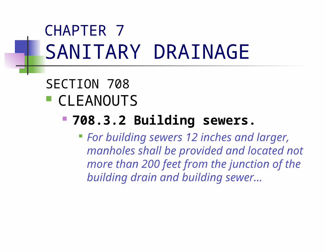
SECTION 708 CLEANOUTS
708.3.2 Building sewers. For building sewers 12 inches and larger,
manholes shall be provided and located not more than 200 feet from the junction of the building drain and building sewer…
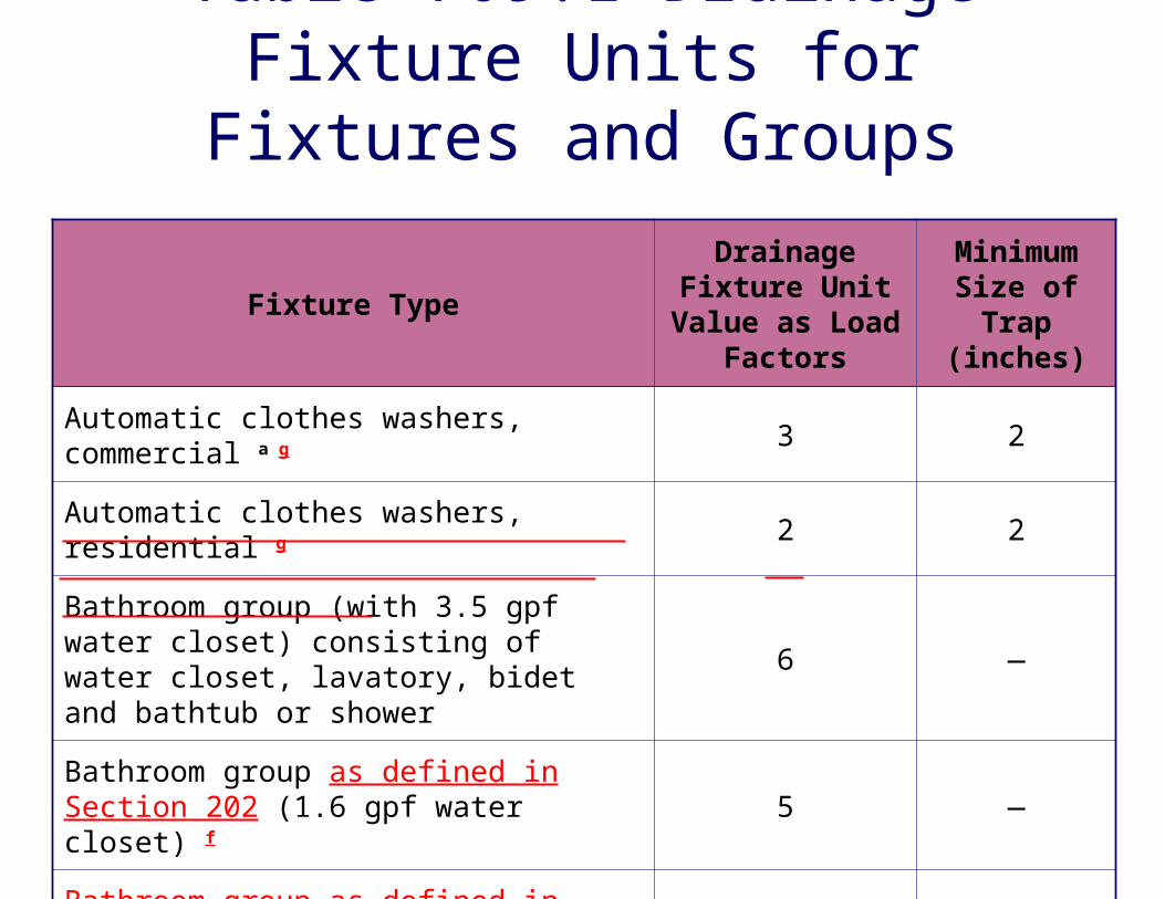
Table 709.1 Drainage Fixture Units for Fixtures and
Groups
Fixture Type
Drainage Fixture Unit
Value as Load Factors
Minimum Size of Trap
(inches)
Automatic clothes washers, commercial a g 3 2
Automatic clothes washers, residential g 2 2
Bathroom group (with 3.5 gpf water closet) consisting of water closet, lavatory, bidet and bathtub or shower
6 —
Bathroom group as defined in Section 202 (1.6 gpf water closet) f
5 —
Bathroom group as defined in Section 202 (water closet flushing greater than 1.6 gpf) f
6 —

Table 709.1 Drainage Fixture Units (cont’d)
Fixture Type
Drainage Fixture Unit
Value as Load Factors
Minimum Size of Trap
(inches)
Bathroom group (with 1.6 gpf flushometer tank with water closet) 5.5
—
Bathtub b (with or without overhead shower or whirlpool attachments)
2 1½
Bidet 1 2 1¼
Combination sink and tray 2 1½
Dental lavatory 1 1¼
Dental unit or cuspidor 1 1¼
Dishwashing machine c, domestic 2 1½
Drinking fountain ½ 1¼
Emergency floor drain 0 2

Table 709.1 Drainage Fixture Units (cont’d)
Fixture Type
Drainage Fixture Unit
Value as Load Factors
Minimum Size of Trap
(inches)
Floor drains 2 2
Kitchen sink, domestic 2 1½
Kitchen sink, domestic with food waste grinder and/or dishwasher
2 1½
Laundry tray (1 or 2 compartments) 2 1½
Lavatory 1 1¼
Shower compartment, domestic 2 1½ 2
Sink 2 1½
Urinal 4 FootnNote d
Urinal, 1 gallon per flush or less 2 e FootnNote d

Table 709.1 Drainage Fixture Units (cont’d)
Fixture Type
Drainage Fixture Unit
Value as Load Factors
Minimum Size of Trap
(inches)
Wash sink (circular or multiple) each set of faucets
2 1½
Water closet, flushometer tank, public or private
4 e FootnNote d
Water closet, private installation 4 Footnote d
Water closet, public installation 6 Footnote d
Water closet, private (1.6 gpf), private installation
3 e FootnNote d
Water closet, private (3.5 gpf), private installation (flushing greater than 1.6 gpf)
4 e FootnNote d
Water closet (1.6 gpf), flushometer tank, private installation 3.5 Footnote d

Table 709.1 Drainage Fixture Units (cont’d)
Fixture Type
Drainage Fixture Unit
Value as Load Factors
Minimum Size of Trap
(inches)
Water closet, public (1.6 gpf) public installation
4 e FootnNote d
Water closet, public (3.5 gpf), public installation (flushing greater than 1.6 gpf)
6 e FootnNote dNotes:f. For fixtures added to a dwelling unit bathroom
group, add the DFU value of those additional fixtures to the bathroom group fixture count.
g. See Section 406.3 for sizing requirements for fixture drain, branch drain, and drainage stack for an automatic clothes washer standpipe.

CHAPTER 7
SANITARY DRAINAGE
SECTION 710 DRAINAGE SYSTEM SIZING
710.3 Underground drainage piping.
This section was in the 2001 FBC, P and has been deleted thereby removing the requirement for minimum 2-inch drains underground

CHAPTER 8
INDIRECT / SPECIAL WASTE No significant changes

CHAPTER 9
VENTS Significant changes

CHAPTER 9
VENTSSECTION 909 WET VENTING
909.1.1 Vertical wet vent. Includes language for vertical wet vents
Shall extend from the connection to the dry vent down to the lowest fixture drain connection
Each fixture shall connect independently Water closet drains shall connect at the same
elevation with other fixture drains connecting above or at same elevation as WC drains
Dry vent connection to vertical wet vent shall be an individual or common vent serving one or two fixtures

CHAPTER 9
VENTS
SECTION 912 COMBINATION DRAIN & VENT
SYSTEM 912.1 Type of fixtures.
No food waste grinders, clinical sinks or standpipes permitted on combination drain and vent systems.

CHAPTER 10TRAPS, INTERCEPTORS & SEPARATORS
Significant changes

CHAPTER 10TRAPS, INTERCEPTORS & SEPARATORS
SECTION 1002 TRAP REQUIREMENTS
1002.4 Trap seals. Floor drains subject to evaporation must have
trap seal primer valve (eliminates deep-seal trap option)

CHAPTER 10TRAPS, INTERCEPTORS & SEPARATORS
SECTION 1003 INTERCEPTORS AND SEPARATORS
Adds requirement for a solids interceptor to separate the discharge before connecting to the grease trap
Adds ASME A112.14.3 or ASME A112.14.4 to grease trap standards

CHAPTER 10TRAPS, INTERCEPTORS & SEPARATORS
SECTION 1003 INTERCEPTORS AND SEPARATORS
1003.5 Grease interceptors. Maximum volume for grease interceptors is
1250 gallons. Interceptors shall be constructed in
accordance with Rule 64E-6, Florida Administrative Code.
Inlet piping shall connect to a tee sweep or baffle that extends 24 inches below the water level.
CHAPTER 11
STORM DRAINAGE No significant changes

CHAPTER 11
STORM DRAINAGE
SECTION 1106 SIZE OF CONDUCTORS, LEADERS
AND STORM DRAINS 1106.7 Scupper sizing.
Scuppers shall be sized in accordance with Table 1106.7

Table 1106.7 Sizing Scuppers for a 5” Per Hour
Rate of Rainfall
Head in inches
Horizontally Projected Roof Area (square feet)
Length of Weir in inches
4 6 8 12 16 20 24
1 230 346 461 692 923 1153 1384
2 641 961 1282 1923 2564 3205 3846
3 1153 1730 2307 3461 4615 5769 6923
4 1794 2692 3589 5384 7179 8974 10769
CHAPTER 12
FUEL PIPING Changes
Chapter 12 (Fuel Piping) of 2001 Florida Building Code, Plumbing is deleted from 2004 Florida Building Code, Plumbing.

CHAPTER 12SPECIAL PIPING & STORAGE SYSTEMS
Chapter 12 is now Special Piping and Storage Systems
No significant changes

CHAPTER 13
REFERENCED STANDARDS Changes – contains an updated listing This chapter lists the standards that
are referenced in various sections of the 2004 Florida Building Code, Plumbing.

Plumbing-Related Chapters
2004 Florida Building Code, Residential

2004 Florida Building Code, Residential
Chapter 25: Plumbing Administration
Chapter 26 General Plumbing Requirements
Chapter 27 Plumbing Fixtures
Chapter 28 Water Heaters
Chapter 29 Water Supply and Distribution
Chapter 30 Sanitary Drainage
Chapter 31 Vents Chapter 32 Traps Chapter 41 Swimming
Pools
Chapters specifically dealing with plumbing:

CHAPTER 25
PLUMBING ADMINISTRATION P2503.4 Gravity sewer test.
(same as Florida Building Code, Plumbing 312.6)
P2503.5.1 Drainage and vent water test. (same as Florida Building Code, Plumbing
312.2)

CHAPTER 26GENERAL PLUMBING REQUIREMENTS
P2601.3 Floodplain management construction standards. Defers authority granted to local
government by Title 44 CFR, sections 59 and 60.
Local floodplain management ordinances are not amendments to the code.

CHAPTER 27
PLUMBING FIXTURES Significant changes
CHAPTER 27
PLUMBING FIXTURES
SECTION P2709 SHOWER RECEPTORS
P2709.2 Lining required. Lining material shall extend not less than 3 inches beyond or around the rough jambs and not less than 3 inches above finished thresholds.

CHAPTER 29WATER SUPPLY & DISTRIBUTION
Significant changes

CHAPTER 29WATER SUPPLY & DISTRIBUTION
SECTION 2904 MATERIALS, JOINTS &
CONNECTIONS P2904.5.1 Under concrete slabs.
PE-AL-PE not permitted under concrete slabs

CHAPTER 29WATER SUPPLY & DISTRIBUTION
No limit on hot water distances like in 2004 Florida Building Code, Plumbing which includes: The hot water system shall be
provided with a method of maintaining the temperature if the developed length of hot water piping from the source of hot water supply to the farthest fixture exceeds 100 feet

CHAPTER 30
SANITARY DRAINAGE Significant changes

CHAPTER 30
SANITARY DRAINAGE
SECTION P3005 DRAINAGE SYSTEM
P3005.2.6 Base of stacks. Allows cleanouts to be installed outside the
building within 3 feet of the building wall.

CHAPTER 30
SANITARY DRAINAGE
SECTION P3005 DRAINAGE SYSTEM
P3005.2.7 Building drains and building sewer junction.
Does not require 3" WM vertical stacks

CHAPTER 31
VENTS Significant changes
CHAPTER 31
VENTS
SECTION 3105 FIXTURE VENTS
P3105.1 Distance of trap from vent.
No limit on WC trap-to-vent distance
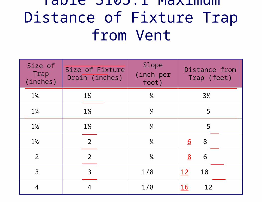
Table 3105.1 Maximum Distance of Fixture Trap
from Vent
Size of Trap
(inches)
Size of Fixture Drain (inches)
Slope(inch per
foot)
Distance from Trap (feet)
1¼ 1¼ ¼ 3½
1¼ 1½ ¼ 5
1½ 1½ ¼ 5
1½ 2 ¼ 6 8
2 2 ¼ 8 6
3 3 1/8 12 10
4 4 1/8 16 12

CHAPTER 32
TRAPS No changes necessary

CHAPTER 41
PRIVATE SWIMMING POOLS Significant changes

CHAPTER 41
SWIMMING POOLS
SECTION R4101 PRIVATE SWIMMING POOLS
R4101.6.1 Conformance Standard. Design, construction and workmanship shall be in conformity with the requirements of ANSI/NSPI 3-99; ANSI/NSPI 4-99; ANSI/NSPI 5-03; and ANSI/NSPI 6-92.

CHAPTER 41
SWIMMING POOLS
SECTION R4101 PRIVATE SWIMMING POOLS
R4104.6 Engineering design. R4101.6.3 Water velocity. Pool piping
shall be designed so the water velocity will not exceed 10 ft/s for pressure piping and 8 ft/s for suction piping, except that the water velocity shall not exceed 8 ft/s in copper tubing.

CHAPTER 41
SWIMMING POOLS
SECTION R4101 PRIVATE SWIMMING POOLS
R4101.6 Engineering design. R4101.6.5 Piping installation. All
piping materials shall be installed in strict accordance with the manufacturer's installation standards.
Exception: Primer and glue on exposed aboveground piping not required to be colored.

CHAPTER 41
SWIMMING POOLS
SECTION R4101 PRIVATE SWIMMING POOLS
R4101.7 Pumps. R4101.7.2 Installation. Pumps shall
be installed in accordance with manufacturer recommendations.

CHAPTER 41
SWIMMING POOLS
SECTION R4101 PRIVATE SWIMMING POOLS
R4101.8 Valves. R4101.8.3 Check valves. Where
check valves are installed they shall be of the swing, spring or vertical check patterns.

CHAPTER 41
SWIMMING POOLS
SECTION R4101 PRIVATE SWIMMING POOLS
R4101.12.1 Pressure test. Removed requirement that all pool piping be
inspected and approved before being covered or concealed.

CHAPTER 41
SWIMMING POOLS
SECTION R4101 PRIVATE SWIMMING POOLS
R4101.21 Pool fittings. R4101.21.2 Skimmers. …skimmers
shall be installed on the basis of one per 800 sq ft of surface area or fraction thereof, and shall be designed for a flow rate of at least 25 gpm per skimmer.
CHAPTER 41
SWIMMING POOLS
SECTION R4101 PRIVATE SWIMMING POOLS
R4101.21 Pool fittings. R4101.21.5 Inlet fittings. Approved
manufactured inlet fittings for the return of recirculated pool water shall be provided on the basis of at least one per 300 sq ft of surface area…

CHAPTER 41
SWIMMING POOLS
SECTION R4101 PRIVATE SWIMMING POOLS
R4101.22 Equipment foundations and enclosures. All mechanical equipment shall be installed as per manufacturer's recommendations…

2004 Florida Building Code, Fuel Gas
Significant changes
Florida Building Code, Fuel Gas
CHAPTER 3 GENERAL REGULATIONS Section 301 (IFGC) General
301.7 Fuel types. Allows serving gas supplier to convert gas
equipment to a different gas.
Florida Building Code, Fuel Gas
Chapter 3, General Regulations Section 301 (IFGC) General
301.10 Wind resistance. Fuel gas appliances and supports that are
exposed to wind shall be designed and installed to resist the wind pressures determined in accordance with the Florida Building Code, Mechanical.

Florida Building Code, Fuel Gas Chapter 3, General Regulations
Section 304 (IFGS) Combustion, Ventilation and Dilution Air
304.1 General. Requirements for air for combustion, ventilation
and dilution of flue gases for gas utilization equipment installed in buildings (refer to sections 304.5 – 304.9 or 304.6 – 304.9)
Direct-vent appliances, gas appliances of other than natural draft design, etc. shall be in accordance with equipment manufacturer’s instructions

Florida Building Code, Fuel Gas
Chapter 3, General Regulations Section 304 (IFGS) Combustion,
Ventilation and Dilution Air 304.5 Indoor combustion air.
Use 304.5.1 or 304.5.2 unless ACH is less than 0.40; then use 304.5.2 to determine required volume of indoor air.

Florida Building Code, Fuel Gas
Chapter 3, General Regulations Section 304 (IFGS) Combustion,
Ventilation and Dilution Air 304.5.3 Indoor opening size and
location. Use 304.5.3.1 and 304.5.3.2 to size and locate
openings used to connect indoor spaces.

Florida Building Code, Fuel Gas
Chapter 3, General Regulations Section 304 (IFGS) Combustion,
Ventilation and Dilution Air 304.6 Outdoor combustion air.
Outdoor combustion air shall be provided through opening(s) to the outdoors in accordance with Section 304.6.1 or 304.6.2. The minimum dimension of air openings shall be not less than 3 inches (76 mm).

Florida Building Code, Fuel Gas
Chapter 3, General Regulations Section 304 (IFGS) Combustion,
Ventilation and Dilution Air 304.7 Combination indoor and
outdoor combustion air. Use 304.7.1 through 304.7.3 when using a
combination of indoor and outdoor combustion air.
Florida Building Code, Fuel Gas Chapter 3, General Regulations
Section 304 (IFGS) Combustion, Ventilation and Dilution Air
304.7 Mechanical combustion air supply.
Where all combustion air is provided by a mechanical air supply system..the combustion air shall be supplied at a rate not less than 0.35 cu ft/min per 1000 Btu/h of total input rating of all appliances in the space.
Florida Building Code, Fuel Gas Chapter 3, General Regulations
Section 304 (IFGS) Combustion, Ventilation and Dilution Air
304.10 Louvers and grilles. Added screens; assume wood louvers will have
25% free area and metal louvers and grilles will have 75% free area; screens shall have a mesh size no smaller than ¼ inch; means have to be provided to prevent main burner from igniting if the louvers fail to open during burner start-up and to shut down the main burner if the louvers close during operation.
Florida Building Code, Fuel Gas
Chapter 3, General Regulations Section 304 (IFGS) Combustion,
Ventilation and Dilution Air 304.11 Combustion air ducts.
Numbers 6–8 have been added.

Florida Building Code, Fuel Gas
Chapter 3, General Regulations Section 304 (IFGS) Combustion,
Ventilation and Dilution Air 304.12 Protection from fumes and
gases. Refers to disposal of corrosive or flammable process
fumes or gases—other than products of combustion.

Florida Building Code, Fuel Gas
Chapter 3 General Regulations Section 305 (IFGC) Installation
Where a code provision is less restrictive, the conditions of the listing and the manufacturer’s installation instructions shall apply.

Florida Building Code, Fuel Gas
Chapter 4 Gas Piping Installations Section 402 (IFGS)
402.2 Maximum gas demand Where an input rating is not indicated, the gas
supplier, equipment manufacturer or a qualified agency are contacted…or the rating from Table 402.2 shall be used for estimating the volume of gas to be supplied.

Table 402.2 Approximate Gas Input for Typical Appliances
ApplianceInput BTU/H
(Approx.)
Space Heating UnitsHydronic boiler
Single familyMultifamily, per unit
Warm-air furnaceSingle familyMultifamily, per unit
100,00060,000
100,00060,000
Space and Water Heating UnitsHydronic boiler
Single familyMultifamily, per unit
120,00075,000
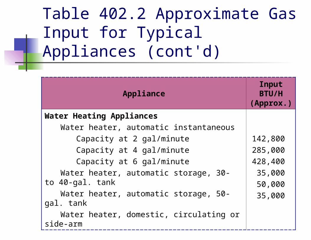
Table 402.2 Approximate Gas Input for Typical Appliances (cont'd)
ApplianceInput BTU/H
(Approx.)
Water Heating AppliancesWater heater, automatic instantaneous
Capacity at 2 gal/minuteCapacity at 4 gal/minuteCapacity at 6 gal/minute
Water heater, automatic storage, 30- to 40-gal. tank
Water heater, automatic storage, 50-gal. tankWater heater, domestic, circulating or side-
arm
142,800285,000428,400
35,00050,00035,000

Table 402.2 Approximate Gas Input for Typical Appliances (cont'd)
ApplianceInput BTU/H
(Approx.)
Cooking AppliancesBuilt-in oven or broiler unit, domesticBuilt-in top unit, domesticRange, free-standing, domestic
25,00040,00065,000
Other AppliancesBarbecueClothes dryer, Type 1 (domestic)Gas fireplace, direct ventGas lightGas logRefrigerator
40,00035,00040,000
2,50080,000
3,000

Florida Building Code, Fuel Gas
Chapter 4 Gas Piping Installations Section 404 (IFGC) Piping System
Installation 404.7 Above-ground outdoor piping. All outdoor piping shall be elevated not
less than 3-1/2 inches above ground and, where installed across roof surfaces, shall be elevated not less than 3-1/2 inches above the roof surface.

Florida Building Code, Fuel Gas
Chapter 4 Gas Piping Installations Section 409 (IFGC) Shutoff Valves
409.5 Equipment shutoff valve. Shutoff valves for vented decorative
appliances and decorative appliances can be placed in remote areas
409.5.1 Shutoff valve in fireplace. Equipment shutoff valves located in the
firebox of a fireplace shall be installed in accordance with the appliance manufacturer’s instructions.

Florida Building Code, Fuel Gas Chapter 4 Gas Piping Installations
Section 411 (IFGC) Appliance Connections
411.1.4 Outdoor appliance connectors. This section provides installation requirements for
installing outdoor gas appliances and is consistent with the National Fuel Gas Code.
Note that lengths shall not exceed 12 feet (3658 mm) and the connection shall only be made in the outdoor area where the equipment is to be used.

Florida Building Code, Fuel Gas
IFGC/IFGS Chapter 8 Referenced Standards Updated reference standards
Florida Building Code, Residential
Chapter 24 Fuel Gas Note that the Florida Building Code,
Residential does not contain the same degree of detail as the Florida Building Code, Fuel Gas.