
2 PROJECT DESCRIPTION - ERM · 2 PROJECT DESCRIPTION ... obtained a mining license from the...
47
ENVIRONMENTAL RESOURCES MANAGEMENT YARA DALLOL BV 2-1 2 PROJECT DESCRIPTION This Chapter provides a description of the proposed Project and associated phases, related activities and ancillary infrastructure. This Project description formed the Terms of Reference for specialist studies associated with this ESIA. The information presented in this Chapter was received from the ongoing Definitive Feasibility Study (DFS) currently being completed by Novopro. 2.1 PROJECT LOCATION Yara Dallol BV holds concession areas in the Danakil Depression in north-eastern Ethiopia. The Project Area is approximately 605km northeast (NE) of the capital of Addis Ababa and 388km northwest (NW) of the port of Djibouti (refer to Figure 1.1 in Chapter 1). The Yara Dallol BV concession areas are defined as (also refer to Table 2.1 and Figure 2.1): 1. Musley: 10.1km 2 (about 2km x 5km), under application for license for exploration activities (1) . 2. North Musley: 18.7km 2 (about 4km x 5km, trapezoid shape), licensed for exploration activities. 3. Crescent: 35.3km 2 polygon, licensed for exploration activities. (1) Please Note – Yara Dallol BV currently holds one exploration license for North Musley and Crescent Concessions (Reference No.: MOM/0130-0134/2000) and is (as a result of the license lapsing) in the process of re-applying for an exploration license for the Musley Concession. Moreover, once mineral resources have been verified and feasibility concerning the proposed Project verified, Yara Dallol BV will be applying for mining rights for all three concessions (North Musley, Crescent and Musley). As a result it is deemed appropriate to include the Musley Concession in the overall ESIA Study Area and to assess the likely social and environmental impacts to sensitive receptors that occur within this area so as to suggest appropriate mitigation / management measures.
Transcript of 2 PROJECT DESCRIPTION - ERM · 2 PROJECT DESCRIPTION ... obtained a mining license from the...
ENVIRONMENTAL RESOURCES MANAGEMENT YARA DALLOL BV
2-1
2 PROJECT DESCRIPTION
This Chapter provides a description of the proposed Project and associated phases,
related activities and ancillary infrastructure. This Project description formed the
Terms of Reference for specialist studies associated with this ESIA.
The information presented in this Chapter was received from the ongoing
Definitive Feasibility Study (DFS) currently being completed by Novopro.
2.1 PROJECT LOCATION
Yara Dallol BV holds concession areas in the Danakil Depression in north-eastern
Ethiopia. The Project Area is approximately 605km northeast (NE) of the capital
of Addis Ababa and 388km northwest (NW) of the port of Djibouti (refer to Figure
1.1 in Chapter 1). The Yara Dallol BV concession areas are defined as (also refer to
Table 2.1 and Figure 2.1):
1. Musley: 10.1km2 (about 2km x 5km), under application for license for
exploration activities (1).
2. North Musley: 18.7km2 (about 4km x 5km, trapezoid shape), licensed for
exploration activities.
3. Crescent: 35.3km2 polygon, licensed for exploration activities.
(1) Please Note – Yara Dallol BV currently holds one exploration license for North Musley and Crescent Concessions (Reference
No.: MOM/0130-0134/2000) and is (as a result of the license lapsing) in the process of re-applying for an exploration license for
the Musley Concession. Moreover, once mineral resources have been verified and feasibility concerning the proposed Project
verified, Yara Dallol BV will be applying for mining rights for all three concessions (North Musley, Crescent and Musley). As a
result it is deemed appropriate to include the Musley Concession in the overall ESIA Study Area and to assess the likely social
and environmental impacts to sensitive receptors that occur within this area so as to suggest appropriate mitigation /
management measures.

ENVIRONMENTAL RESOURCES MANAGEMENT YARA DALLOL BV
2-2
Table 2.1 Coordinates of the Yara Dallol BV Concession Areas in the Danakil Depression,
Ethiopia
Crescent Exploration
License Area
North Musley Exploration
License Area
Musley Mining
License Area
Corner
Easting
(m) Northing (m)
Easting
(m) Northing (m)
Easting
(m) Northing (m)
1 637472 1570413 628226 1581465 632807 1570088
2 633859 1579906 629949 1576367 631612 1574997
3 638489 1581590 629994 1576346 633590 1575415
4 638813 1581592 633332 1577691 634755 1570528
5 640876 1575907 631905 1582219
6 639558 1576435
7 638042 1575912
8 637659 1573867
9 638746 1570887
Please Note - coordinates are given in geographic format, UTM zone 37, hemisphere N of the Adindan, Ethiopia
datum (Ellipsoid: Clarke 1880)
Figure 2.1 Yara Dallol BV Concession Areas
Please Note - Yara Dallol BV is in the process of re-applying for an exploration license for the Musley
Concession, and as a result it is deemed appropriate to include the Musley Concession in the overall ESIA Study
Area.
ENVIRONMENTAL RESOURCES MANAGEMENT YARA DALLOL BV
2-3
As such, the total area of all three concession areas is 64.1km2.
Yara Dallol BV is one of three concession holders within this area of the Danakil
Depression. The other concession holders are:
1. Allana Potash Corp. - Allana has completed feasibility study and has
obtained a mining license from the Ethiopian Ministry of Mines (MoM). They
are continuing with the development of a potash mining project.
2. G&B Central Africa Resources Plc - G&B is conducting exploration work in
their license areas. Exploration commenced with diamond core drilling in
May 2011.
These concession holders, together with their concession areas are illustrated in
Figure 2.2. This Figure provides context as to the location of these concession
areas, relative to the Yara Dallol BV concession, and within the broader region.
It must be noted that Yara Dallol BV has relinquished 25% of the Crescent
Concession (as required by the Ethiopian Mining Laws) that is occupied by
Mount Dallol (this is illustrated in yellow in Figure 2.2). The reason for this is to
ensure that no mining activities are undertaken on Mount Dallol or the
immediate surroundings.

ENVIRONMENTAL RESOURCES MANAGEMENT YARA DALLOL BV
2-4
Figure 2.2 Concession Areas in the Danakil Depression
Please Note - Yara Dallol BV is in the process of re-applying for an exploration license for the Musley Concession, and as a result it is deemed appropriate to include the Musley
Concession in the overall ESIA Study Area
`

ENVIRONMENTAL RESOURCES MANAGEMENT YARA DALLOL BV
2-5
2.2 PROJECT BACKGROUND
The Yara Dallol Potash Project has been ongoing since 2008. In May 2012, Yara
International obtained majority shares in the project; however, prior to 2012, the
majority shareholder of the Yara Dallol Potash Project was an Indian company,
Sainik Potash Private Ltd.
The early engineering work was completed by the Potash Consultancy Firm
Ercosplan. Ercosplan completed a Pre-Feasibility Mining Feasibility Study report
in September 2012, summarizing the work completed to that date.
A new project consultant team was assembled, and comprised of Novopro Project
Development and Management, and Agapito Associates, a firm specializing in
the design of underground mines, with extensive solution mining expertise.
After reviewing the data available from the 2012 Mining Feasibility Study, the
team completed a Scoping Study based upon a simplified and more site-specific
process, and prepared a preliminary design and associated project CAPEX and
OPEX estimates, corresponding to the new design proposed. This Scoping Study
was approved by Yara International, resulting in the initiation of a (Definitive)
Feasibility Study in September 2013, which is scheduled to finish in January 2015.
2.3 PHASES OF THE PROPOSED YARA DALLOL POTASH PROJECT
In general, mining projects are developed in the following set phases:
Exploration (ongoing);
Engineering Scoping Study
Pre-Feasibility Study
(Definitive) Feasibility Study
Preparation for Execution (bridge engineering, contracting etc.);
Execution (detailed engineering and construction);
Operation (mining); and
Decommissioning and Closure.
Each of these phases have a different combination of activities and the
commencement of each phase is dependent on the outcome and success of its
predecessor. It must be noted that the scope of the Project proposed, and the
associated ESIA study, relates to the construction, operation and
decommissioning and closure phases. However, the recommendations of the
ESIA study and management and mitigation measures in the associated social
and environmental management plans, will need to be taken into account during
the planning phase, as well as subsequent phases of the proposed Project.
The above-mentioned Project phases are discussed in this Section.

ENVIRONMENTAL RESOURCES MANAGEMENT YARA DALLOL BV
2-6
2.3.1 Exploration Phase
To date, the proposed Project has performed a considerable amount of work on
the characterisation of resource within its concessions. This Section details the
exploration activities undertaken by Yara Dallol BV between October 2008 and
July 2014.
Geological Exploration
In total, 49 holes have been drilled to date. These drill holes targeted the
following deposit horizons (the configurations of the horizons typical for Musley
North Zone 1 are presented in Figure 2.3):
Sylvinite
Upper Carnallitite
Lower Carnallitite
Kainitite
Figure 2.3 Deposit Horizons
During the process of drilling and coring wells, core samples extracted from the
various mineralized horizons were analysed for their mineral content by a
geochemical laboratory and tonnage of extractable resources available for
Surface

ENVIRONMENTAL RESOURCES MANAGEMENT YARA DALLOL BV
2-7
exploitation was estimated. The mineral resource estimate thus derived is a major
component in the evaluation of the overall economic feasibility of the proposed
Project. The results of exploration drilling activities to date are presented in Table
2.2.

ENVIRONMENTAL RESOURCES MANAGEMENT YARA DALLOL BV
2-8
Table 2.2 Thickness and Average Grade of the Deposit Horizons in the Early Potash bearing Drill Holes for the Yara Dallol Potash
Project
Potash
Horizon
Thickness
(m)
Sylvite
wt%
Halite
wt%
Carnallitite
wt%
Kainite
wt%
Kieserit
wt%
Anhydrite
wt%
Polyhalite
wt%
Insolubles
wt%
KCl
wt%
Sylvinite Member (28 holes for calculation)
Average 3.35 27.83 57.19 3.92 0.95 - 7.65 0.63 1.72 27.83
Minimum 0.34 11.36 45.16 0.02 - - 0.37 - - 11.36
Maximum 6.7 46.42 70.25 16.90 16.90 - 20.79 12.98 26.97 46.42
Upper Carnallitite (22 holes for calculation)
Average 3.29 1.83 27.07 53.20 2.55 1.46 4.67 0.06 0.15 16.68
Minimum 0.20 - 11.06 1.74 - - 0.48 - - 4.72
Maximum 17.75 8.73 65.08 81.91 50.13 6.10 9.54 1.18 0.80 25.65
Lower Carnallitite (26 holes for calculation)
Average 6.32 0.09 20.26 30.83 2.82 37.93 1.81 - 0.92 8.84
Minimum 2.00 - 11.43 0.24 - 0.23 0.31 - - 0.06
Maximum 34.55 2.27 65.55 48.89 20.27 52.46 16.16 - 14.57 13.76
Kainitite Member (28 holes for calculation)
Average 6.80 0.07 32.75 1.11 61.16 3.54 0.73 0.43 0.33 19.77
Minimum 1.50 - 21.05 - 0.33 0.01 - - - 12.21
Maximum 9.45 0.48 94.90 5.13 78.33 14.20 7.07 1.84 8.05 23.89

ENVIRONMENTAL RESOURCES MANAGEMENT YARA DALLOL BV
2-9
Figure 2.4 below shows the SandvikDE710 drilling rig used to produce the
aforementioned core samples. Furthermore, Figure 2.5 provides an example of a
core sample.
Figure 2.4 Exploration Drilling Rig

ENVIRONMENTAL RESOURCES MANAGEMENT YARA DALLOL BV
2-10
Figure 2.5 Example of Core Sample
Preliminary Seismic Surveys
The Project has performed a preliminary seismic reflection survey (refer to Figure
2.6) to determine the seismic velocity depth structure of the deposit. The results
from this survey are used to migrate and calibrate the velocity data from the 2D
survey. The general understanding of the local geology will be the base for
designing a future 2D seismic survey. The main goals of the preliminary seismic
survey were to provide an image of the subsurface and establish the continuity of
the potash horizons as well as the overall structure of the deposit.
An example of the outcome of the preliminary vertical seismic profiling survey
interpretation is included in Figure 2.6.

ENVIRONMENTAL RESOURCES MANAGEMENT YARA DALLOL BV
2-11
Figure 2.6 Example of the Interpretation of the a 2D Seismic Survey
Establishment of a Site Camp
During the exploration phase, a camp was established, which has grown from a
few persons to its present day capacity of approximately 200 people. This camp
provides shelter and services to the project personnel who participate in the Yara
Dallol Potash Project. The camp is equipped with a clinic and has a full-time
medic and nurse on site. The clinic also occasionally treats locals with medical
emergencies.
2.3.2 Definitive Feasibility Study
The exploration phase (as described in Section 2.3.1) is currently guiding the
Definitive Feasibility Study phase, and it is during this phase that the ESIA team
has worked closely with the engineering design team. This has allowed possible
Project processes, layouts and design alternatives to be investigated, and the
identification and assessment of impacts and establishment of suitable
mitigation/management measures that can be incorporated into the overall
Project design. These anticipated impacts and associated mitigation measures are
presented in the form of an ESIA Report (this report) and associated Management
Plans (refer to Part II).
It is expected that the Definitive Feasibility Study will be completed in January
2015. Yara will review the information in the study and decide whether or not to
pursue the project.

ENVIRONMENTAL RESOURCES MANAGEMENT YARA DALLOL BV
2-12
2.3.3 Pilot Well Testing
A major part of the DFS was to establish the feasibility of solution mining this
deposit. Two pilot wells (PW-8 and PW-09) were established and operated for a
period of over 7 months. Each well has progressed well and the mining technique
has been confirmed as suitable with information received during this testing. The
wells are currently producing potash brines that are consistent with the estimates
obtained from dissolution tests of recovered core samples during the exploration
phase.
2.3.4 Bridge Engineering Phase
Bridge Engineering is required to investigate and identify project components on
the critical path that affect the overall timing of the project. Currently it is
assumed that bridge engineering will start in November 2014 and continue to
November of 2015.
2.3.5 Construction Phase
The construction phase cannot commence prior to the completion of the
Definitive Feasibility Study and the Bridge Engineering Phase as well as the
approval of the associated ESIA Study by the MoM and grant of Mining license
by The Ethiopian Ministry of Mines (MoM). On the assumption that the mine will
be established and that all relevant rights and permits will be obtained, it is
assumed that construction will commence in December 2015 for a duration of
approximately 24 months, ending in December 2017. The construction phase will
likely include the following initial construction activities:
Construction of Staff Living Quarters;
Location and start-up of the borrow pits.
Establishment of the rock crushing plant.
Construction of Access Roads (roads will be made of local material and will
be covered with an anti-dusting agent;
Construction of Evaporation Ponds;
Construction of Brine and Water Pipelines;
Construction of the mine processing facility (Process Plant), including office
and support facilities; and

ENVIRONMENTAL RESOURCES MANAGEMENT YARA DALLOL BV
2-13
In addition to the above mentioned facilities, the proposed Project will have a set
aside area for tailings (Tailings Management Area – TMA) and basic
infrastructure within the Solution Mining Area.
The locality of this infrastructure with respect to the concession boundaries is
illustrated in Figure 2.7.
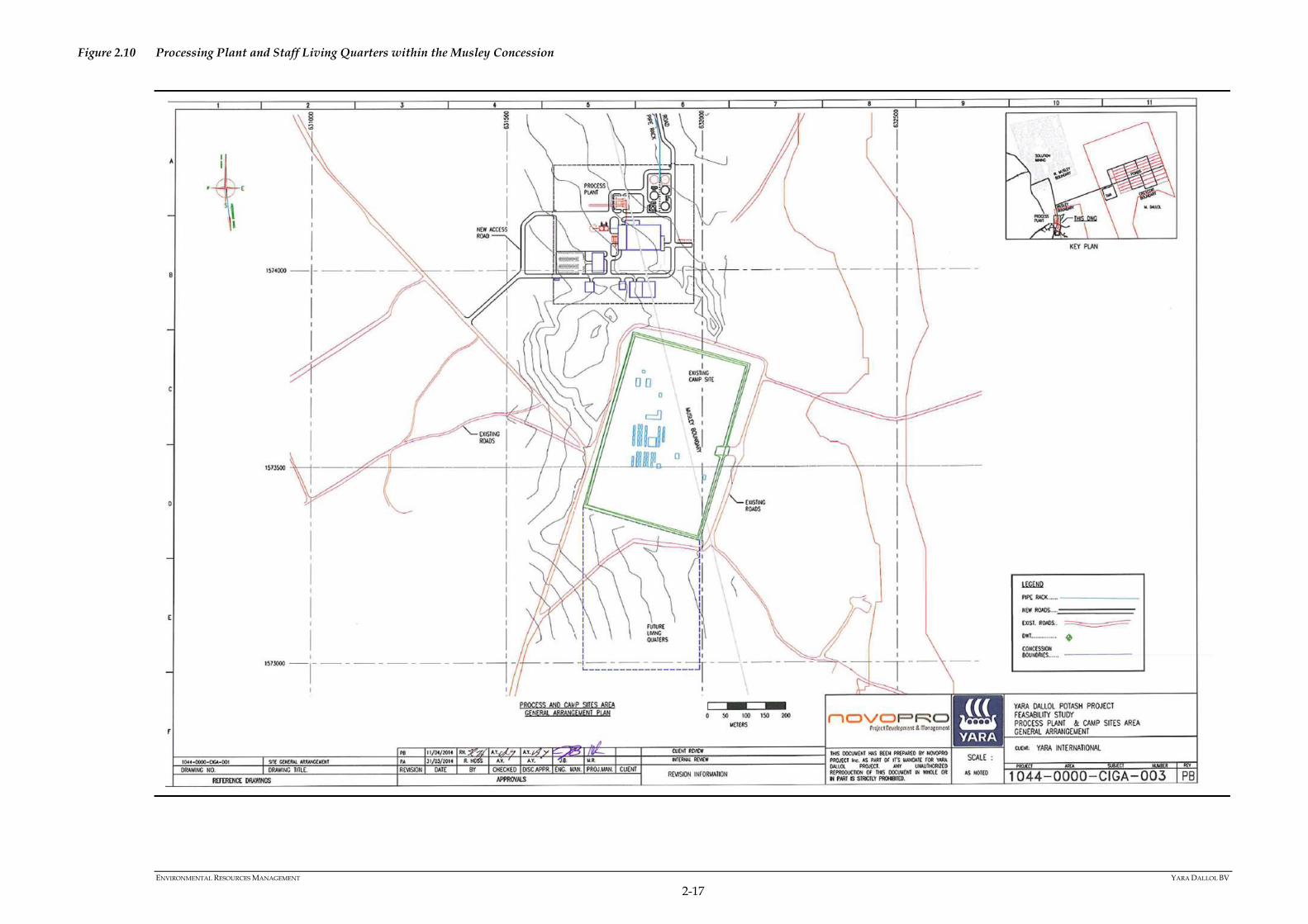
More detailed drawings illustrating the size and layout of the Evaporation Ponds,
TMA, Processing Plant, Staff Living Quarters and Solution Mining Area are
provided in Figure 2.8 to Figure 2.13. From a visual perspective, the maximum
heights of this infrastructure will be as follows:
TMA – 15m in year- 1 and 30m for the remaining years.
Evaporation Pond – 2m (the height of the perimeter berm).
Staff Living Quarters – average height of buildings will be 4m.
Solution Mining Area – a solution well has a maximum height between 1 and
2m and the blanket oil tank and oil separator will have a maximum height of
about 7.5m (refer to Figure 2.20 and Figure 2.21 on Page 2-38 and Page 2-39
respectively). It should be noted that mining will commence at the south west
corner of the North Musley concession.
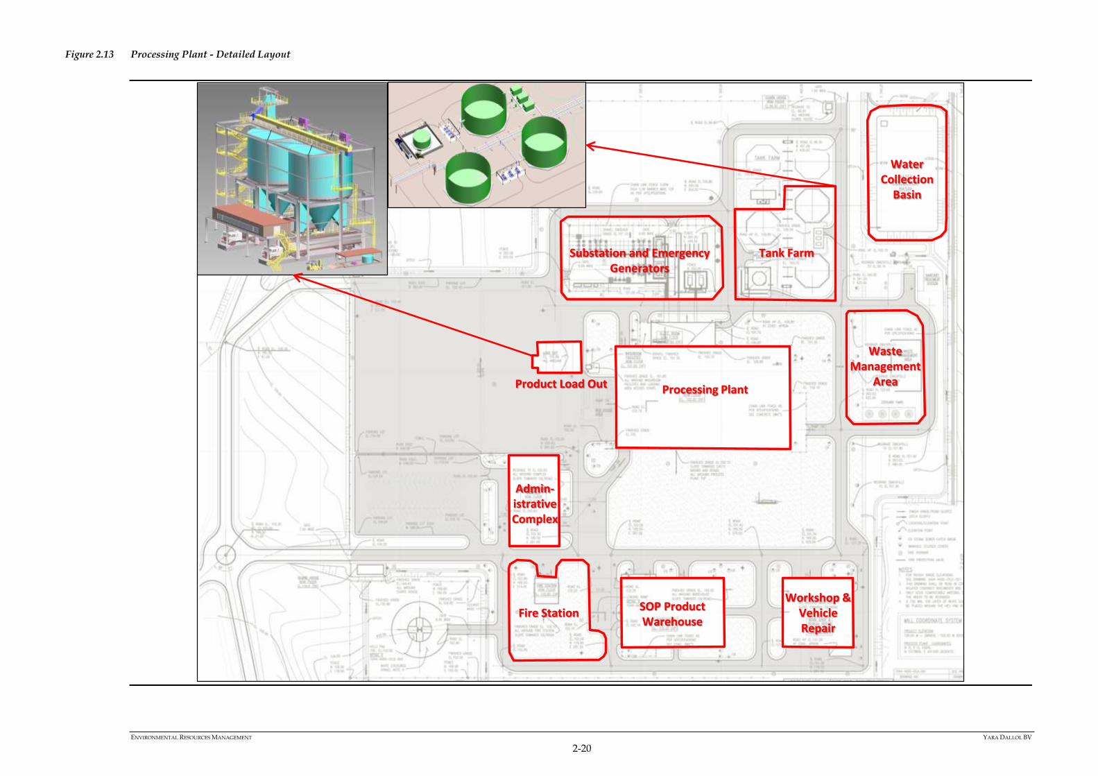
Processing Plant – maximum height of about 30m and will include Project
support facilities such as electrical substation, emergency generators (4 X
2.5MW generators, with stack heights of approximately 10m), above ground
diesel storage tanks, temporary waste management areas, product
warehousing, workshop and vehicle repair area and administrative buildings
(refer to layout of the Processing Plant in Figure 2.13.
Section 2.3.6 of this Chapter describes in detail the processes associated with this
infrastructure and the mining and processing of potash bearing brine.
Public Access Restrictions
It must be noted that the Staff Living Quarters and Processing Plant will be
fenced and access will be restricted; however, road and pipeline corridors will not
be fenced and access will not be restricted.

ENVIRONMENTAL RESOURCES MANAGEMENT YARA DALLOL BV
2-14
Figure 2.7 Proposed Yara Dallol Potash Project - Infrastructure Arrangement

ENVIRONMENTAL RESOURCES MANAGEMENT YARA DALLOL BV
2-15
Figure 2.8 Evaporation Ponds within the Crescent Concession

ENVIRONMENTAL RESOURCES MANAGEMENT YARA DALLOL BV
2-16
Figure 2.9 Tailings Management Area with the Crescent Concession
ENVIRONMENTAL RESOURCES MANAGEMENT YARA DALLOL BV
2-17
Figure 2.10 Processing Plant and Staff Living Quarters within the Musley Concession

ENVIRONMENTAL RESOURCES MANAGEMENT YARA DALLOL BV
2-18
Figure 2.11 Processing Plant and Staff Living Quarters within the Musley Concession
ENVIRONMENTAL RESOURCES MANAGEMENT YARA DALLOL BV
2-19
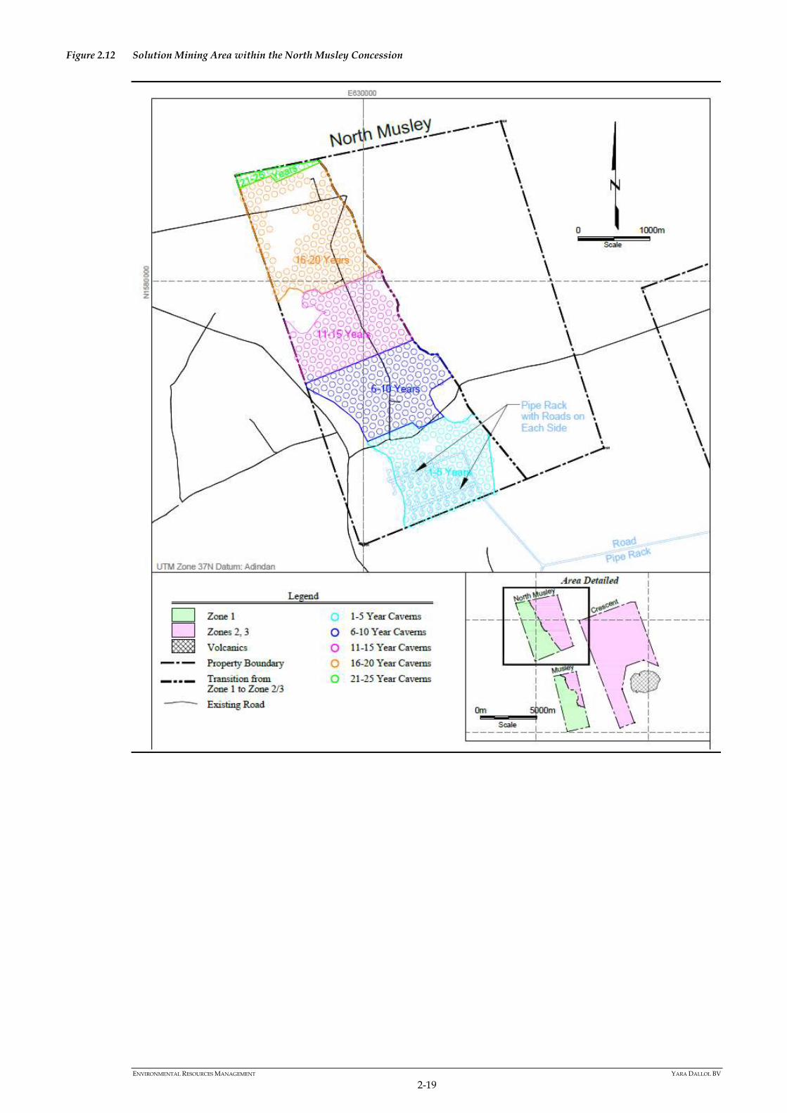
Figure 2.12 Solution Mining Area within the North Musley Concession
ENVIRONMENTAL RESOURCES MANAGEMENT YARA DALLOL BV
2-20
Figure 2.13 Processing Plant - Detailed Layout
Tank FarmSubstation and Emergency Generators
Processing PlantProduct Load Out
Admin-istrativeComplex
SOP Product Warehouse
Workshop & Vehicle Repair
Waste Management
Area
Fire Station
Water Collection
Basin
ENVIRONMENTAL RESOURCES MANAGEMENT YARA DALLOL BV
2-21
2.3.6 Operational Phase
Once the construction phase of the proposed Project is complete, the
operational phase will commence. Early estimates indicate a potential life of
mine of approximately 20 years for the west half of the North Musley
concession.
Solution Mining
Mining Area
As is mentioned earlier in this Chapter, the ESIA will focus on three concession
areas. Based on data collected during the exploration phase, the resource
within these three concessions has been divided into the following three zones
(refer to Figure 2.14):
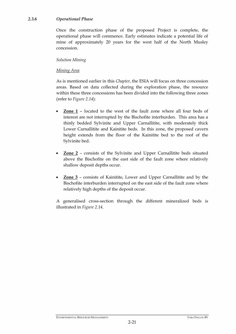
Zone 1 – located to the west of the fault zone where all four beds of
interest are not interrupted by the Bischofite interburden. This area has a
thinly bedded Sylvinite and Upper Carnallitite, with moderately thick
Lower Carnallitite and Kainitite beds. In this zone, the proposed cavern
height extends from the floor of the Kainitite bed to the roof of the
Sylvinite bed.
Zone 2 – consists of the Sylvinite and Upper Carnallitite beds situated
above the Bischofite on the east side of the fault zone where relatively
shallow deposit depths occur.
Zone 3 – consists of Kainitite, Lower and Upper Carnallitite and by the
Bischofite interburden interrupted on the east side of the fault zone where
relatively high depths of the deposit occur.
A generalised cross-section through the different mineralized beds is
illustrated in Figure 2.14.
ENVIRONMENTAL RESOURCES MANAGEMENT YARA DALLOL BV
2-22
Figure 2.14 Cross Section Showing Typical Caverns in Zones 1, 2 and 3
Optimal Locations for Solution Mining
Factors determining the most optimal locations for solution mining include:
Depth of the resource zone and the ability to maintain necessary vertical
and lateral pressures.
Rock mechanics characteristics of the geologic units including density,
shear strength and creep strain rates.
Solubilities of particular evaporite minerals to determine brine
concentrations of particular mineralized units.
Geometry of the resource zone including thickness, sequence and
inclination (dip) of the mineralized zones
Taking these factors into account, Zone 1 in North Musley was chosen as the
location for initial mining (refer to Figure 2.12).
Zones 2 and 3 (Figure 2.14) were not considered at this time due to significant
challenges, including –
Area of excessive (greater than 15%) inclination, which results in
significant brine dilution;
Limited resource thickness (in the case of Zone 2); and
Depths and temperatures in the case of the Crescent concession.
Mining at Musley was not considered because of several issues, including:

ENVIRONMENTAL RESOURCES MANAGEMENT YARA DALLOL BV
2-23
Uncertainty about the extent of the dissolution of the mineralized zone
associated with the former Parsons Mine;
The shallow depth of the mineralized zone (1); mineralization (2) and
uncertainty regarding the correct cut of depth for mining
The lack of success with several pilot caverns in 2011 and 2012; and
The unconsolidated nature of the overlying materials.
Mining Layout
The following layout was developed for the establishment of caverns located
in Zone 1 on the North Musley concession area.
Ultimately between 450 and 500 caverns are proposed in this mining area
(refer to Figure 2.12), each with a 35 to 45m radius, and a pillar width of 20 to
45 m (refer to Figure 2.15). Assuming an average mineralized thickness of
between 13 and 14m and recovery of 80% of the final brines, the average
cavern life in Zone 1 of North Musley is estimated at 1.5 to 2.0 years.
Between 35 and 45 caverns are estimated to be required to achieve an annual
production rate of 600 kilotonnes per year (ktpy) of sulfate of potash (SOP)
with the number of caverns that need to be replaced each year estimated at
between 22 and 28 (the life span of each cavern is estimated to be between 1.5
and 2.0 years). The mine life for mining in Zone 1 in the North Musley area at
this production rate was estimated to be approximately 21 years.
Figure 2.15 Cavern and Pillar Geometry for North Musley
(1) Please Note - because of the shallow depth the overburden is not consolidated and cannot support a cavern at a shallow
depth. The roof would collapse. (2) Please Note - because of the shallow depth the overburden is not consolidated and cannot support a cavern at a shallow
depth. The roof would collapse.

ENVIRONMENTAL RESOURCES MANAGEMENT YARA DALLOL BV
2-24
The radius of the caverns (40m typical) was chosen as a trade-off between the
desirability of maximizing the volume produced per well and the need to
maintain rock mechanical stability. The 40m typical radius results in a cavern
footprint of about 5,000m2.
The caverns in North Musley Zone 1 will be between 80m and 270m below
ground surface and are to be accessed by a single well that will be used for
both water and oil blanket injection, and potash-bearing brine extraction. The
dual direction flow will be accomplished by means of an inner string inside
the casing. Potash-bearing brine will be pumped via a pipeline from the well
through to the evaporation ponds (refer to Figure 2.16).
Figure 2.16 Typical Well and associated Cavern
Oil (Diesel) Blanket
A low-density, immiscible blanket is used in solution mining to prevent
unwanted, upward dissolution of the cavern roof by the solvent, to prevent
leaching of salt from around the cemented casing of the well and to protect the
cemented casing from corrosion. The blanket material needs to be inert so that
it does not dissolve the salt rock and needs to be less dense than the solvent
liquid or the brine produced in the cavern. The blanket effectively floats at the
top of the cavern where it protects the roof from dissolution. The use of a
blanket material is intended to increase stability by controlling the height and
diameter of the cavern.
Almost all modern commercial solution mining operations use blanketing, as
well as other technologies such as sonar imaging, to control cavern shape and
optimise the rate and extent of salt dissolution.
Gaseous blankets (for example nitrogen and air) require high pressures (i.e. in
excess of 100 bar) when used in deeper solution mining operations, which can
become a health and safety concern. As such, liquid hydrocarbons (viz. diesel)
are preferred for all deep solution mining operations.

ENVIRONMENTAL RESOURCES MANAGEMENT YARA DALLOL BV
2-25
Diesel has been chosen as the preferred blanket technology, due to its higher
viscosity, and greater resistance to migrating through microporous or
microfractured zones compared to compressed air.
At this stage it is anticipated that approximately 35 to 40m3 of diesel will be
required per mined cavern mined and that approximately 22 to 28 caverns
will be developed each year. Furthermore, the recovery rate of blanket oil
(diesel) is expected to be approximately between 50 and 75 percent.
Brine Extraction
Based on laboratory solubility testing, it is expected that brine composition in
the North Musley concession area will have a potassium chloride content of
between 35 and 105 grams per litre. To satisfy a 600ktpy SOP production rate
(based on an 85% plant recovery), a production brine flow rate of 800 to
900m3/h is required, with an injection of 850 to 950m3/h of solvent water.
Resource Recovery
The recoverable resource has been estimated based on the geologic model, the
cavern shapes and the density and thickness of potash bearing members and
is presented in Table 2.3.
Table 2.3 Summary of Minable Resource (Tonnes) for Zone 1 of the North Musley
Concession
Parameter Value
Number of caverns 450-550
Sylvinite (tons) 5,988,286
Upper Carnallitite (tons) 1,180,942
Bischofite (tons) 177,667
Lower Carnallitite (tons) 11,896,695
Kainitite (tons) 16,407,980
Total resource in 497 caverns (tons) 35,473,903
Post Solution Mining Process – Processing
Evaporation Ponds
From the wells, it is proposed to pump brine to a series of solar evaporation
ponds (these are illustrated in Figure 2.7 on Page 2-14 and Figure 2.8 on Page 2-
15) in which brine will be evaporated resulting in the crystallisation of
potassium-, magnesium- and sodium-bearing salts. These salts will then be
removed from the evaporation ponds and directed to the processing plant
(illustrated in Figure 2.7 [Page 2-14], Figure 2.11 [Page 2-18] and Figure 2.13
[Page 2-20]).
Process Plant
Figure 2.17 illustrates the process flow of intermediate potash product through
the processing plant.
ENVIRONMENTAL RESOURCES MANAGEMENT YARA DALLOL BV
2-26
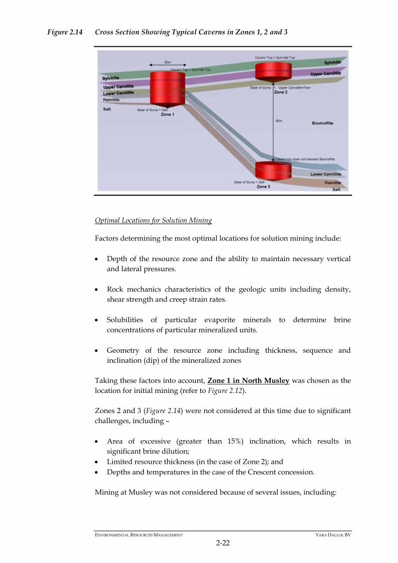
Figure 2.17 Process Flow of Potash Processing
Scrapers harvest crude potash from the evaporation ponds and this is
transported to the processing plant.
In the processing plant harvested salts will initially be crushed following
which crushed salts will enter the processing plant. The processing plant
converts the Potassium Bearing salts to K2SO4 (Potassium Sulphate). The
effluent from the dewatering process will be directed back to the evaporation
ponds, NaCl will be discarded to the Tailings Management Area. Excess
MgCl2 brine will be used to backfill the depleted caverns once they are
available. Until that time the excess brine will be discharged onto the salt
flats. The K2SO4 crystals produced are then further dewatered and dried
producing the SOP product. The dryer will be electric and not fuel powered.
The above mentioned process has been designed to produce approximately
600ktpa (79mtph) of SOP product. The processing plant is illustrated in Figure
2.13 on Page 2-20 and has been designed to produce both granular and
standard grade SOP with flexibility to fluctuate the quantity of each based on
market conditions.
Transfer Pumps
In order to transfer intermediate product and process water between
operating areas, the several pumps will be used. These pumps vary in size
from 500kW down to 15kW. The location of each pump was used in the Noise
Modelling.
ENVIRONMENTAL RESOURCES MANAGEMENT YARA DALLOL BV
2-27
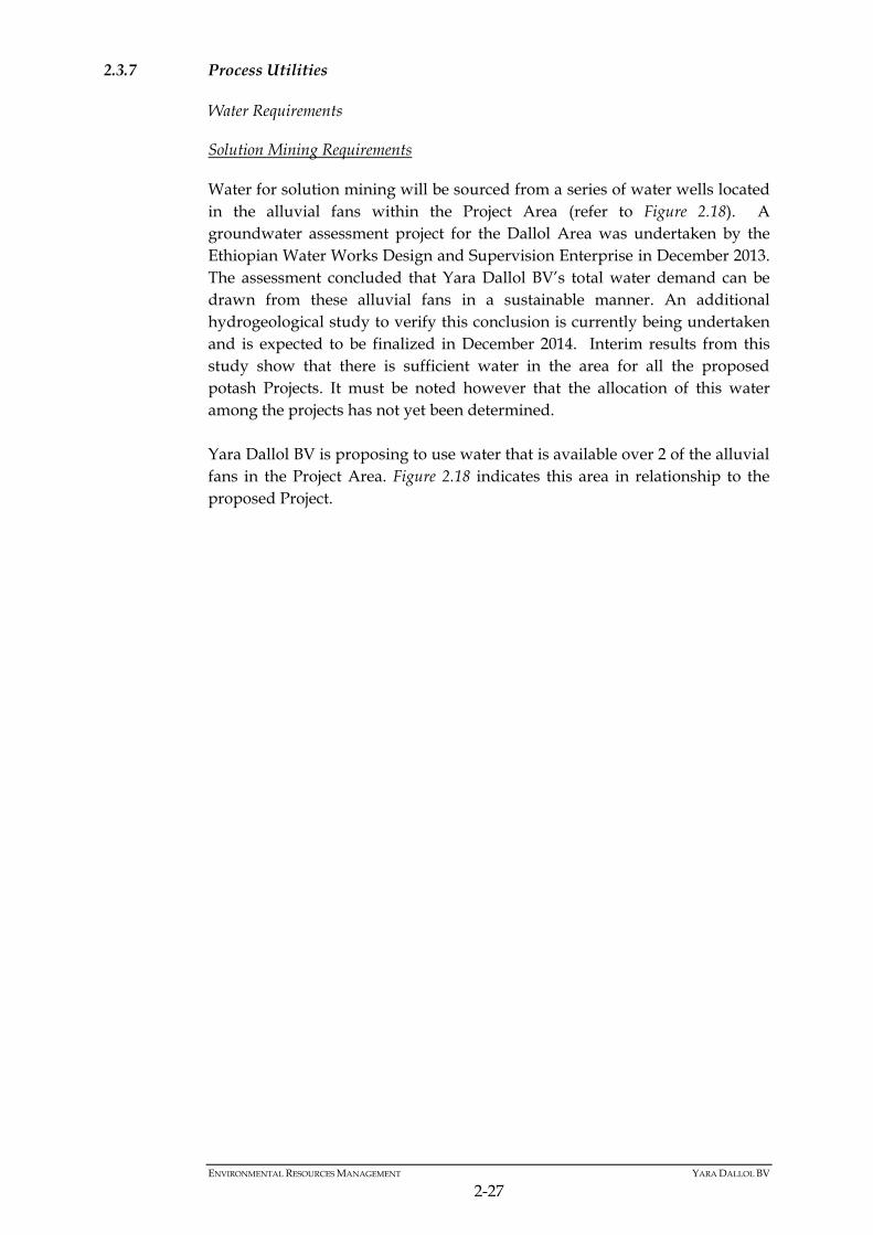
2.3.7 Process Utilities
Water Requirements
Solution Mining Requirements
Water for solution mining will be sourced from a series of water wells located
in the alluvial fans within the Project Area (refer to Figure 2.18). A
groundwater assessment project for the Dallol Area was undertaken by the
Ethiopian Water Works Design and Supervision Enterprise in December 2013.
The assessment concluded that Yara Dallol BV’s total water demand can be
drawn from these alluvial fans in a sustainable manner. An additional
hydrogeological study to verify this conclusion is currently being undertaken
and is expected to be finalized in December 2014. Interim results from this
study show that there is sufficient water in the area for all the proposed
potash Projects. It must be noted however that the allocation of this water
among the projects has not yet been determined.
Yara Dallol BV is proposing to use water that is available over 2 of the alluvial
fans in the Project Area. Figure 2.18 indicates this area in relationship to the
proposed Project.
ENVIRONMENTAL RESOURCES MANAGEMENT YARA DALLOL BV
2-28
Figure 2.18 Potential Water Source for the Proposed Project

ENVIRONMENTAL RESOURCES MANAGEMENT YARA DALLOL BV
2-29
The amount of water to be used annually is less than the estimated annual
recharge rate of the aquifers. This removal is therefore sustainable. The
volume of water extracted along with its temperature and its conductivity
from each well will be monitored on a continual basis for any changes. Since
the fans are located some distance from the production well fields, water will
be abstracted via dedicated pump stations and transported via pipeline to the
project site. Water from these alluvial fans will have the following
characteristics (refer to Table 2.4):
Table 2.4 Solution Mining Water Properties
Parameter Unit Data
Volume m3/h 850-950
Temperature °C 45
Total TDS ppm ≤32,000
Process Water Requirements
Process water used in the purification process will also be pumped from the
alluvial fans. Process water for the proposed Project has the following
characteristics (refer to Table 2.5):
Table 2.5 Process Water Properties
Parameter Unit Data
Volume m3/h 650
Temperature °C 45
Total TDS ppm ≤2,500
This water will also be used as firefighting water.
Potable Water
Potable water is to be used for drinking and sanitary needs. A potable water
system will be put in place that will meet regulatory requirements in terms of
quality. It is estimated that 20 to 30m3/h of potable water will be required
during the operational phase of the proposed Project.
Waste
Waste Water
Waste water produced from washing of equipment and regular maintenance
will be recycled in the operational process. Waste water shall not contain
foreign contaminants prohibited by environmental laws and regulation.
Sanitary waste water from toilets and urinals shall be collected in an
underground sewer system that will be constructed as part of the processing
plant’s sanitary facilities. A self-contained treatment system will be put in
place to treat sanitary water. As part of this treatment process, sludge will be

ENVIRONMENTAL RESOURCES MANAGEMENT YARA DALLOL BV
2-30
removed every 8 to 12 months and disposed of by a licensed contractor.
Treated waste water will be re-used in the production process.
Solid Waste
The proposed Project will result in the following waste categories –
Reusable materials such as glass and plastic bottles, non-contaminated
containers, concrete blocks and wood;
Dry non-combustible waste such as glass, plastic, concrete and styrofoam;
Dry combustible waste such as cloth, wood trim, kitchen greases,
cardboard which cannot be shredded;
Metal;
Organic waste – compostable;
Shredded paper and cardboard;
Biomedical waste; and
Hazardous waste in designated containers; such as drums, bags and
pallets for containment of batteries, greases, oil filters, contaminated soils,
fluorescent tubes and ink cartridges.
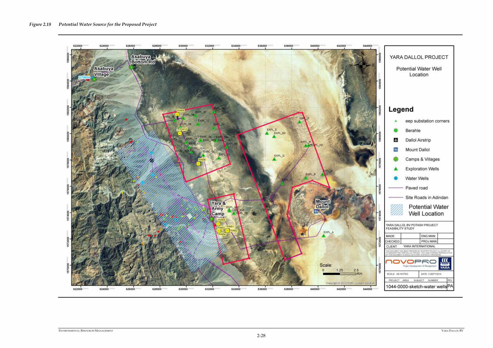
These waste categories are elaborated on in Table 2.6.
ENVIRONMENTAL RESOURCES MANAGEMENT YARA DALLOL BV
2-31
Table 2.6 Waste Types
Waste Type Generated/Location End Use
HAZARDOUS WASTE
Used greases Maintenance shop Incineration
Used batteries and power supplies Site wide Recycle or Dispose via Outside Contractor
Soiled pails and drums Process Plant Incineration
Soiled parts Process Plant Recycle or Dispose via Outside Contractor
Soiled rags Process Plant Incineration
Used absorbents Process Plant Incineration Oil filters Maintenance shop Incineration Used Oil Maintenance shop Recycle or Dispose via Outside Contractor
Ink cartridges Site wide Incineration
Laboratory Wastes Plant site Recycle or Dispose via Outside Contractor
Potable water sanitation Plant site Discharge to the Process
Fluorescents Site wide Recycle or Dispose via Outside Contractor
Hydrocarbon contaminated soils Site wide Incineration
Obsolete Electronics Site wide Recycle or Dispose via Outside Contractor
Sewage waste Site wide Sewage Treatment Plant
Medical wastes Clinic Incineration
SPECIAL WASTE
Used filters or bags from baghouses Process Plant Incineration
Radioactive Wastes (viz. from logging wells) Well Field Recycle or Dispose via Outside Contractor
RECYCLABLES WASTES
Scrap copper, brass, aluminium, precious metals Maintenance shop Recycle or Dispose via Outside Contractor
Scrap iron and steel including punctured and crushed spray cans Maintenance shop/Well field Recycle or Dispose via Outside Contractor
REUSABLE WASTES
Clean wood Process Plant N/A – will be reused
Clean drums, pails, boxes Site wide N/A – will be reused Wooden Pallets Process Plant N/A – will be reused Packaging Materials Process Plant N/A – will be reused Plastic and glass Bottles Site wide N/A – will be recycled Mechanical parts Maintenance shop N/A – will be reused Hardware (viz. old tools, fasteners, etc.) Maintenance shop N/A – will be reused Ducts Process Plant N/A – will be reused Building’s roof and side metal sheets Process Plant N/A – will be reused Paint Site wide N/A – will be reused
NON-HAZARDOUS WASTE

ENVIRONMENTAL RESOURCES MANAGEMENT YARA DALLOL BV
2-32
Waste Type Generated/Location End Use
Cloth Site wide Incineration
Wood trim Site wide Incineration
Kitchen greases (from grease trap) Process Plant Incineration
Paper and cardboard Site wide Incineration
Concrete Site wide Landfill
Gypsum Site wide Landfill
Glass Site wide Landfill
Ashes Incinerator Landfill
Dried paint containers Maintenance shop Landfill
Plastics Site wide Incineration
Tires Maintenance shop Landfill/ Incineration
Fiberglass Maintenance shop Landfill/ Incineration
Kitchen waste Process Plant Compost
Sanitary sludge Wastewater treatment Compost
Shredded paper and cardboard Site wide Compost

ENVIRONMENTAL RESOURCES MANAGEMENT YARA DALLOL BV
2-33
Waste management for the proposed Project will promote the 4R concept –
that is Reduce, Reuse, Recycle and Reclaim/Recover. Disposal will be the last
resort option. These concepts can be defined as:
Reduce – minimise the amount of waste produced by procuring bulk
goods rather than packaged goods and training workers to reduce waste
production.
Reuse – clean and maintain non-single use items for multiple uses when
and where possible.
Recycle – transform waste to be used as a primary matter in fabrication of
other good.
Reclaim/Recover – transform waste into a value added product (e.g.
composting).
Disposal – through incineration, onsite burial or offsite disposal by a
competent specialist contractor.
Waste management infrastructure proposed for the Project includes –
Waste Management Centre – the centre will receive all site waste, where it
will be sorted and managed as appropriate, either for its reuse, recycling
or disposal. All waste movements will be recorded in a register by the
Waste Management Centre attendant.
Incinerator - incineration will be achieved adjacent to the landfill. Wood,
shrub, cardboard that cannot be shredded, non-compostable kitchen
waste, biomedical waste and oily rags shall be burned at least once a week
when climatic conditions allow. No plastic, rubber or polymer will be
burned. Excessive wind is a no-go condition for incineration. The
incinerator shall be surrounded by a 15 meters building free area, which
will act as fire break. This operation shall be performed under close
surveillance to keep the fire under control at all times.
Composter - a Big Hannah Composter will be used for the management of
organic waste. Shredded paper and cardboard from offices will also be
sent to the composter. Excess organic waste which cannot be dealt with by
composting will be incinerated and ashes buried in the landfill.
Landfill – only non-hazardous waste will be sent for burial at the landfill.
The landfill will consist of a series of unlined cells which will be opened
and covered on a daily basis. A backhoe and bulldozer will be available
for the operation of the landfill.
ENVIRONMENTAL RESOURCES MANAGEMENT YARA DALLOL BV
2-34
It must be noted that for during the construction phase of the proposed Project
all organic waste will also be composted in a similar fashion to that currently
used.
Plant By-product – NaCl and MgCl2
NaCl is a by-product of the evaporation ponds and the crystallisation process.
The estimated production flow rate of wet NaCl is approximately 133 tonnes
per hour (1.0 million tons per year). The intent is to store the NaCl in a Tailing
Management Area (TMA) (refer to the location and design of the TMA in
Figure 2.7 and Figure 2.9 on Page 2-14 and Page 2-16 respectively) of where
some natural dissolution will return it to the surface. NaCl by-product will be
transferred to the TMA by truck, where it will then be dumped and spread.
Dust emissions from the TMA are expected to be low and the tailings will
have 10% moisture content.
As there will be no spent mining caverns available for backfilling during the
first year of operations waste MgCl2 brine will be discharged to the salt flats or
used as a dust suppressant on unpaved road surfaces.
As solution-mining caverns become available to be backfilled, the MgCl2 brine
will be used for cavern backfilling firstly, with the excess to be used for dust
suppression and road maintenance.
Electricity
Electricity will be sourced from Ethiopian Electric Power (EEP) during the
operational phase of the proposed Project. EEP is planning on supplying a
230kV electrical line (1) to a common substation proposed in the greater Project
Area (refer to location in Figure 2.19). From this substation each of the mining
companies is responsible to source their own power, likely through a 132kV
line. The Yara Dallol BV line, from the EEP substation to the site, is
approximately 1.8km long. The average load of the facility is estimated to be
less than 32 MW (32,000kW – refer to Table 2.7). The timelines associated with
construction of the 230kV EEP owned electrical line have not been finalised;
however, it is estimated by EEP that funding for this line will be secured in
2014. Construction of the electrical line should take 2 to 3 years with a
completion date estimated between November 2016 and 2017.
(1) It must be noted that EEP is fully responsible for the design and construction of the Overhead Transmission Line

ENVIRONMENTAL RESOURCES MANAGEMENT YARA DALLOL BV
2-35
Figure 2.19 Proposed Location of the Common EEP Substation and Proposed Routing of the Yara Dallol BV 132 kV Power Line from the EEP Substation to the Yara Project Area
ENVIRONMENTAL RESOURCES MANAGEMENT YARA DALLOL BV
2-36
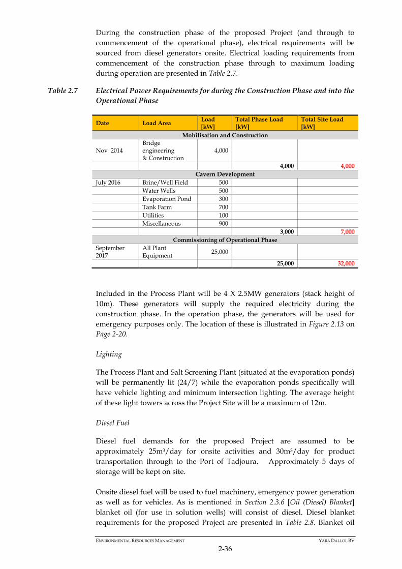
During the construction phase of the proposed Project (and through to
commencement of the operational phase), electrical requirements will be
sourced from diesel generators onsite. Electrical loading requirements from
commencement of the construction phase through to maximum loading
during operation are presented in Table 2.7.
Table 2.7 Electrical Power Requirements for during the Construction Phase and into the
Operational Phase
Date Load Area Load [kW]
Total Phase Load [kW]
Total Site Load [kW]
Mobilisation and Construction
Nov 2014 Bridge engineering & Construction
4,000
4,000 4,000
Cavern Development
July 2016 Brine/Well Field 500
Water Wells 500
Evaporation Pond 300
Tank Farm 700
Utilities 100
Miscellaneous 900
3,000 7,000
Commissioning of Operational Phase
September 2017
All Plant Equipment
25,000
25,000 32,000
Included in the Process Plant will be 4 X 2.5MW generators (stack height of
10m). These generators will supply the required electricity during the
construction phase. In the operation phase, the generators will be used for
emergency purposes only. The location of these is illustrated in Figure 2.13 on
Page 2-20.
Lighting
The Process Plant and Salt Screening Plant (situated at the evaporation ponds)
will be permanently lit (24/7) while the evaporation ponds specifically will
have vehicle lighting and minimum intersection lighting. The average height
of these light towers across the Project Site will be a maximum of 12m.
Diesel Fuel
Diesel fuel demands for the proposed Project are assumed to be
approximately 25m3/day for onsite activities and 30m3/day for product
transportation through to the Port of Tadjoura. Approximately 5 days of
storage will be kept on site.
Onsite diesel fuel will be used to fuel machinery, emergency power generation
as well as for vehicles. As is mentioned in Section 2.3.6 [Oil (Diesel) Blanket]
blanket oil (for use in solution wells) will consist of diesel. Diesel blanket
requirements for the proposed Project are presented in Table 2.8. Blanket oil

ENVIRONMENTAL RESOURCES MANAGEMENT YARA DALLOL BV
2-37
will be stored in a 90 to 100m3 oil tank (refer to Figure 2.20) at the well field in
North Musley.
Upon completion of a well, blanket oil will be recovered (the recovery rate of
blanket oil [diesel] is expected to be approximately between 50 and 75 percent)
and directed to a series of oil / water separators (Figure 2.20 and Figure 2.21).
Recovered diesel will be reused as blanket oil.
The diesel will be delivered via tanker truck from a depot (refer to Figure 2.20
and Figure 2.21). Diesel requirements are expected to be approximately 50 to
60m3/day. The grade of diesel that will be delivered and used on site is the
same as throughout Ethiopia. Currently it contains 0.5% (5,000 parts per
million) sulphur.
Table 2.8 Blanket Oil Requirements for the Proposed Project
Item Value Units Notes
Solution Mining Blanket Oil Parameters
Oil Blanket Requirement for Operating Caverns ±1,320 m3/year
Blanket Oil Losses
Total Blanket Oil Make-Up for Mining ±150 m3/year
Oil Make-Up
Total Yearly Make-Up Blanket Oil Requirement ±250 m3/year
Oil Requirement
Total Blanket Oil in Circulation 1700 to
1900 m3
Requirement
+ Make-Up

ENVIRONMENTAL RESOURCES MANAGEMENT YARA DALLOL BV
2-38
Figure 2.20 Blanket Oil Tank and Oil Separator at Well Fields in North Musley

ENVIRONMENTAL RESOURCES MANAGEMENT YARA DALLOL BV
2-39
Figure 2.21 Isometric View of Blanket Oil Tank and Oil Separator at Well Fields in North Musley

ENVIRONMENTAL RESOURCES MANAGEMENT YARA DALLOL BV
2-40
Compressed Air
The plant will require two compressed air systems; one for use in the
processing plant and one for instrumentation use.
2.4 MOBILE EQUIPMENT
The following is a proposed list of diesel mobile equipment will be required
for the life of the proposed Project (refer to Table 2.9):
Table 2.9 Diesel Mobile Equipment Requirements
VEHICLE DESCRIPTION
QTY PURPOSE
Front-end Loader 3 TMA Maintenance (1), Solution Mining Well Field Expansion (1)Port
Bulldozer 2 Wellpad and Road Maintenance and Solution Mining Well Field Expansion (1), TMA Maintenance (1)
Excavator 2 Wellpad and Road Maintenance, Solution Mining Well Field Expansion, TMA Maintenance and Berm Canal Maintenance (1)
Harvesting Scraper 10 Pond Harvesting (10)
Graders 5 Pond Windrows (4), Wellpad and Road Maintenance and Solution Mining Well Field Expansion (1)
Oil Tanker Truck 3 General Distribution of Diesel Fuel around Site (2), Diesel Blanket Oil Distribution and Recovery (2)
Drill Rig 2 Drilling and Casing of Production Wells (2)
Workover Rig 1 Workover of Production Wells (1)
Backhoe 1 Drilling Support Vehicle (1) Road Maintenance and Solution Mining Well Field Expansion
Logging Unit 1 For Core Logging during Drilling
Low-bed Truck 1 Heavy Mobile Equipment Transport
Heavy Duty Flat Bed, c/w cab
1 Construction Equipment Transport (1)
Hydraulic Telescopic Mobile Crane
1 Drilling Support vehicle (1), Wellhead Skid Installation & Plant Maintenance (1)
Bobcat 2 Drilling Support Vehicle (1) Wellpad and Road Construction (1) Ponds Management and Crushing area (1)
Water Tanker Truck General Distribution of Water around Site , Drilling Support Vehicle
Brine Tanker Truck 1 MgCl2 Road Anti-dusting Treatment
Dump Truck 10 Tailings Trucking to TMA
Product Transport Trucks 96 Transport Product to Port of Tadjoura
200 kW Portable Genset 1 General Purpose around Site
Medium Duty Flat-bed Truck c/w Lifting Arm
2 Drill Pipe and Casing Transport, Wellfield Pipe Transport and Pipeline Repair
Fire Truck (fully equipped)
1 Firefighting
Ambulance (fully equipped)
1 Medical Services and Transport
Welding Trailer 1 Trailer-mounted Welding Machine
Mobile Workshop 1 General Purpose around Site
Scissor Lift 1 Outdoor diesel powered
5-Seat SUV 11 Personnel Transport around Site
5-seat flat bed utility vehicle
6 4 x 4
Portable Light Towers, Diesel-Powered
3 Night Lighting
Vacuum Truck 10 Sanitary waste management

ENVIRONMENTAL RESOURCES MANAGEMENT YARA DALLOL BV
2-41
VEHICLE DESCRIPTION
QTY PURPOSE
Electrical Utility Truck (Boom Truck)
1 Power Line and Substation Repairs
Bus 5 Transport of Personnel to Site
2.5 EMPLOYMENT
The project has been providing employment since 2010 (as part of the
exploration phase) and has built a positive relationship between staff and the
local inhabitants. The number of local inhabitants employed has increased
since 2010. Should the proposed Project go ahead into the construction and
operational phases, skilled construction workers, general helpers,
management, drillers, labour etc. will all be required. It is expected that the
proposed Project will employ approximately 1,000 and 800 persons during the
construction and operational phases respectively.
Table 2.10 Staff Estimate for the Operational Phase of the Proposed Project
Skill Set Estimated # of Positions
Yara Dallol Site including Camp
Senior Management 18
Degreed Employees 42
Tradesmen 133
Skilled Labor 242
Unskilled/Helpers 46
Product Truck Drivers 52
Serdo Site
Senior Management 1
Degreed Employees 1
Tradesmen 0
Skilled Labor 11
Unskilled/Helpers 3
Product Truck Drivers 104
Tadjoura Port and Camp
Senior Management 2
Degreed Employees 0
Tradesmen 0
Skilled Labor 8
Unskilled/Helpers 18
Product Truck Drivers 52
Please Note – office administrative employment opportunities will also be available in Addis
and/or Mekele.
2.6 WORKING HOURS
Production of Potash is planned at rates of 600ktpa per year operating 24
hours per day 316 days per year. Solution mining will run continuously 24
hours a day, 7 days per week and 365 days per year.
Construction is proposed to be undertaken on a 24 hour basis, 7 days per
week over a period of 24 months. It should be noted that the staff estimates

ENVIRONMENTAL RESOURCES MANAGEMENT YARA DALLOL BV
2-42
provided in Section 2.5 assume an 8 hour working day or a 48 hour working
week.
2.7 ANCILLARY INFRASTRUCTURE
2.7.1 Transport Route
Yara Dallol BV has identified two road connections from the Yara Dallol
Potash Project Area through to Djibouti. These are discussed below
Preferred Long-term Road connection for use during the Operational Phase
Refer to Route illustrated in Figure 2.22.
It is currently proposed that the preferred long-term road connection will be
used during the operational phase of the proposed Project to transport potash
product (Sulphate of Potash) from the proposed Processing Plant at the Yara
Dallol Potash Project Site through to the Port of Tadjoura, Djibouti for export.
This long-term road has a weight limitation of approximately 60 metric tonnes
Gross Combined Vehicle Weight. The truck cabs and trailers that are
currently being evaluated are approximately 20MT, leaving a payload of SOP
of approximately 40MT.
The preferred long-term road connection runs south from the Yara Dallol
Potash Project Area down the Danakil Basin (the ‘lowland route’) and
intersects the existing road about 20km north of Afdera to Serdo, through to
the proposed new border crossing at Balho and down through to the Port of
Tadjoura.
The proposed route associated with this road connection will traverse due
south along an existing paved road through to the Hamad Ela Village. From
Hamad Ela the route continues south through the Danakil Basin to the town of
Afdera. This section of the route will be upgraded to a heavy duty asphalt
road by the Ethiopian Roads Authority who has already commenced
engineering studies.
The route will then join the Afdera to Serdo road which has a length of 183km
and is currently in excellent condition following the laying of a new asphalt
surface in 2009, although traffic levels have been low. The route will then
follow the Ethiopian National Highway 2 (N2) for 130km through to the
proposed Balho border crossing between Ethiopia and Djibouti.
Approximately 80km of the road between Dichito and Balho (on the Ethiopian
PLEASE NOTE –
The ancillary infrastructure mentioned in this Section does not form part of the scope of the
ESIA, as much of this infrastructure is either existing or is being upgraded/ constructed
independently by the Ethiopian and Djibouti governments. This Section does however provide a
brief summary of what ancillary infrastructure is proposed.

ENVIRONMENTAL RESOURCES MANAGEMENT YARA DALLOL BV
2-43
side) remains in poor condition or unfinished and will be completed once the
road from the Port of Tadjoura and the proposed Balho border crossing point
has been constructed.
From Balho, the route winds down to the Port of Tadjoura via a high capacity
asphalt road that is currently being built, passing through the towns of Dorra
and Randa. The total length of the road is approximately 110km. The road is
still under construction and is expected to be complete by December 2015.
Short-term Road Connection for use during the Construction Phase
Yara Dallol BV is proposing to use a short term highland road connection
during the construction phase of the proposed Project and during the time
that the road through the Danakil Basin between Hamad Ela and Afdera is
been built. It is anticipated that this road connection will be used during the
construction phase of the proposed Project to transport construction
materials/machinery to the Project Area from the Port of Djibouti.
This short-term road connection follows the same route as the long-term road
connection; however, at Hamad Ela Village the route runs due west (the
‘highlands route’) through to the town of Berahale. From Berahale the route
runs south west into the highlands and follows an existing road to the town of
Shirket. From Shirket the route decreases in altitude due east and intersects
the existing road in just north of Afdera. From here the road continues south
to Serdo, through to the proposed new border crossing at Galafi and down
through to the Port of Djibouti.
From Afdera the route connects to the existing Afdera to Serdo road,
following which the same routing as the long-term option is followed through
to the Port of Tadjoura, Djibouti.
PLEASE NOTE –
In order to understand any key social and environmental sensitivities and key risks to the
proposed Project, associated with the use of this ancillary infrastructure, Yara Dallol BV
appointed ERM to undertake an additional Socio-environmental Screening Study (SESS); the
objective of this SESS is was to investigate the potential social and environmental sensitivities of
the proposed road connection for both the short term import of construction
material/machinery and the long term transportation of potash product to the Port of Tadjoura.
By integrating social and environmental considerations as early as possible into the logistics
planning process, it is intended that the risk of any potential negative environmental and social
impacts and risks to the proposed Project may be avoided or reduced.
As part of this SESS the following aspects were investigated:
Biodiversity;
Social (including Health and Safety); and
Cultural and Heritage
It must be reiterated that the proposed road connection and associated Socio-environmental
Screening Study do not form part of the scope of the ESIA

ENVIRONMENTAL RESOURCES MANAGEMENT YARA DALLOL BV
2-44
Figure 2.22 Proposed Long-Term Lowland Road Connection for the Export of Potash Product through the Port of Tadjoura, Djibouti
ENVIRONMENTAL RESOURCES MANAGEMENT YARA DALLOL BV
2-45
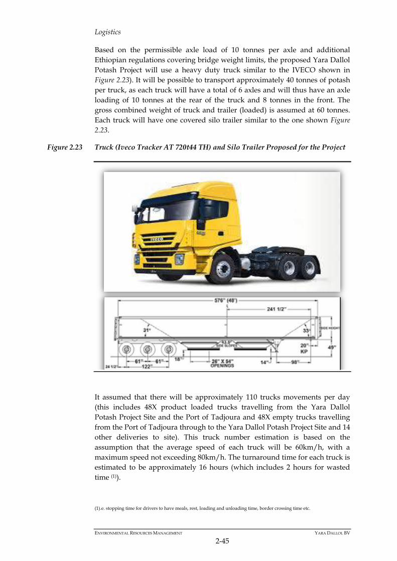
Logistics
Based on the permissible axle load of 10 tonnes per axle and additional
Ethiopian regulations covering bridge weight limits, the proposed Yara Dallol
Potash Project will use a heavy duty truck similar to the IVECO shown in
Figure 2.23). It will be possible to transport approximately 40 tonnes of potash
per truck, as each truck will have a total of 6 axles and will thus have an axle
loading of 10 tonnes at the rear of the truck and 8 tonnes in the front. The
gross combined weight of truck and trailer (loaded) is assumed at 60 tonnes.
Each truck will have one covered silo trailer similar to the one shown Figure
2.23.
Figure 2.23 Truck (Iveco Tracker AT 720t44 TH) and Silo Trailer Proposed for the Project
It assumed that there will be approximately 110 trucks movements per day
(this includes 48X product loaded trucks travelling from the Yara Dallol
Potash Project Site and the Port of Tadjoura and 48X empty trucks travelling
from the Port of Tadjoura through to the Yara Dallol Potash Project Site and 14
other deliveries to site). This truck number estimation is based on the
assumption that the average speed of each truck will be 60km/h, with a
maximum speed not exceeding 80km/h. The turnaround time for each truck is
estimated to be approximately 16 hours (which includes 2 hours for wasted
time (1)).
(1).e. stopping time for drivers to have meals, rest, loading and unloading time, border crossing time etc.
ENVIRONMENTAL RESOURCES MANAGEMENT YARA DALLOL BV
2-46
During the trip the drivers will need to be switched out. For this purpose it is
proposed to have a private truck stop located near Serdo. This facility will
contain the following infrastructure:
Washrooms;
Lounge/waiting room;
Parking area for 100 trucks divided into full and empty. At least two
separate secure entrances should be provided to not mix traffic;
Parking area for support/operations staff and transfer busses;
Office space for logistics control/reporting;
Security post;
Mechanic office; and
Small truck parts depot for common items (wiper blades, window
washing fluid, tires, etc.).
It is proposed that the drivers will live in Semera, the capital of the Afar
region. With this arrangement the drivers would be able to spend every other
day with their families.
Once the trucks arrive in Tadjoura and dump their loads they will proceed to
an offsite Yara Camp. This camp is sized to hold the 48 trucks and 52 drivers
as well as having the following infrastructure:
Camp for minimum of 52 drivers;
Lounges or common areas for entertainment (pool tables, games, TVs,
etc.);
Parking area for 50 trucks (empty);
Parking area for support/operations staff delivers (food, drinks, etc.);
Office space for logistics control/reporting;
Security post;
Tow Truck and mechanic (Djibouti side breakdowns);
Small truck parts depot for common items (wiper blades, window
washing fluid, tires, etc.); and
Medical facility.
2.7.2 Electrical Overhead Transmission Lines (OHTL)
As is mentioned in Section 2.3.7, the EEP is planning to bringing in a 230kV
OHTL from the main Mekele substation to a proposed Dallol electrical
substation in the greater Project Area (refer to location of this substation in
Figure 2.19 on Page 2-35). The design of this line has been completed by EEP.
2.7.3 Post Transport Product Processing
The SOP final granulated product from the site will require screening to
ensure that it meets product specifications prior to loading onto a ship. This

ENVIRONMENTAL RESOURCES MANAGEMENT YARA DALLOL BV
2-47
screening will produce a small amount of off spec material that will be
recycled into the standard product storage facility and will be used again.
2.7.4 Port Infrastructure
The Port Authority of Djibouti is currently developing the Greenfield
Tadjoura port largely for Ethiopian exports as well as for some imports. Area
is available at this port for bulk products, such as Potash. As such, it is
proposed to transport SOP product from site through to Tadjoura Port in
Djibouti for export. This port is currently under construction and will be
completed by September 2016 before the proposed Yara Dallol potash Project
commences with mining operations.
Facilities at the port will include –
Two large storage domes with a capacity of 45k tonnes each;
A truck unloading facility;
Equipment for loading SOP product onto a common conveyor; and
Support areas including offices, control room, washrooms, QC lab,
maintenance, utilities, etc.