Concrete Coring System - Geoprobe Systems®...Operating Instructions Page 2 Concrete Coring System...
8
Concrete Coring System Installation and Operation Instructions Instructional Bulletin No. 00-4000 PREPARED: September, 2000
Transcript of Concrete Coring System - Geoprobe Systems®...Operating Instructions Page 2 Concrete Coring System...

ConcreteCoringSystem
Installation and OperationInstructions
Instructional Bulletin No. 00-4000
PREPARED: September, 2000
Operating Instructions Page 2 Concrete Coring System
Instructions for Installing and Operatingthe Concrete Coring System
1.0 Objective
Geoprobe machine operators must often advance tools into the subsurface at locations having a surface coveringof concrete, asphalt, brick, or rock. Such materials are generally impenetrable with standard direct push tooling.In order to operate direct push equipment at these locations, a hole must be provided through the otherwiseimpenetrable surface layer.
This document identifies the procedure for cutting and removing a core from the ground covering using a ConcreteCoring System powered by a typical Geoprobe® direct push machine. Instructions are given for units equippedwith either a GH40-Series or GH60 Hydraulic Hammer. Direct push tooling may then be advanced through theremaining open hole.
2.0 Required Equipment
GeneralConcrete Coring Kit, Geoprobe PN 16840
includes: Water Swivel Assembly, Geoprobe PN 15315Spring Clips (3), Geoprobe PN 15536Coring Support Plate, Geoprobe PN 16290Coring Plate Holding Bracket (2), Geoprobe PN 16466Coring Plate Holding Bracket Handle (2), Geoprobe PN 16468Flat Washers (2), 5/16-in.Bit Extension, 1.25-7NC thread x 12-in. length, Geoprobe PN 15050
Diamond Core Bit, 5 in. OD x 13 in. length, Geoprobe PN 15008Diamond Core Bit, 8 in. OD x 13 in. length, Geoprobe PN 16486Diamond Core Bit, 12 in. OD x 13 in. length, Geoprobe PN 16080Adjustable wrenches (2), capable of opening 1-7/16 to 1-13/16 inches (may substitute pipe wrenches of suitable size).Screw drivers (2), flat bladeSteel hammer
GH40-Series Hammer OnlyAnvil Retainer Cap Assembly, Geoprobe PN GH4200
GH60 Hammer OnlyGH60 Retainer Cap, Geoprobe PN 7617GH60 Hex Adapter, 2.5- x 1.0-inch, Geoprobe PN 14779
3.0 Initial Assembly of Coring Tools
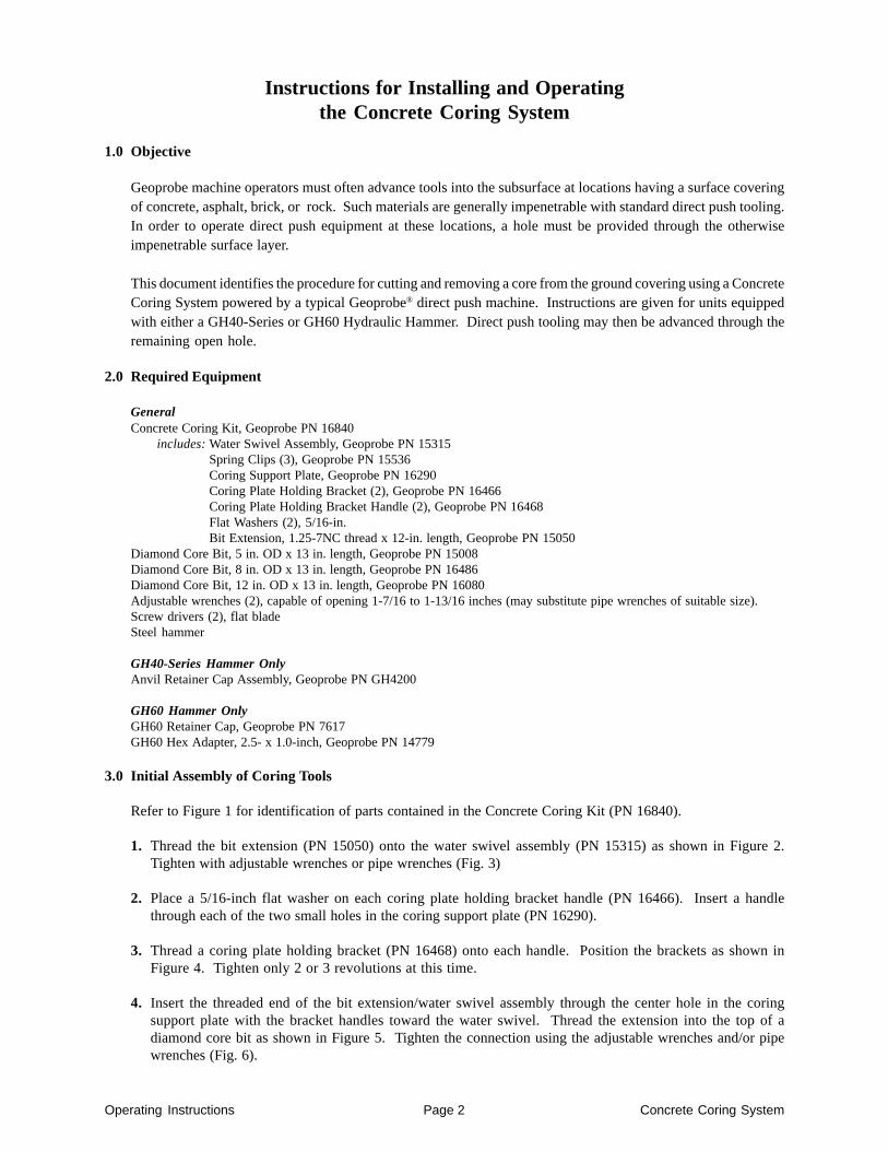
Refer to Figure 1 for identification of parts contained in the Concrete Coring Kit (PN 16840).
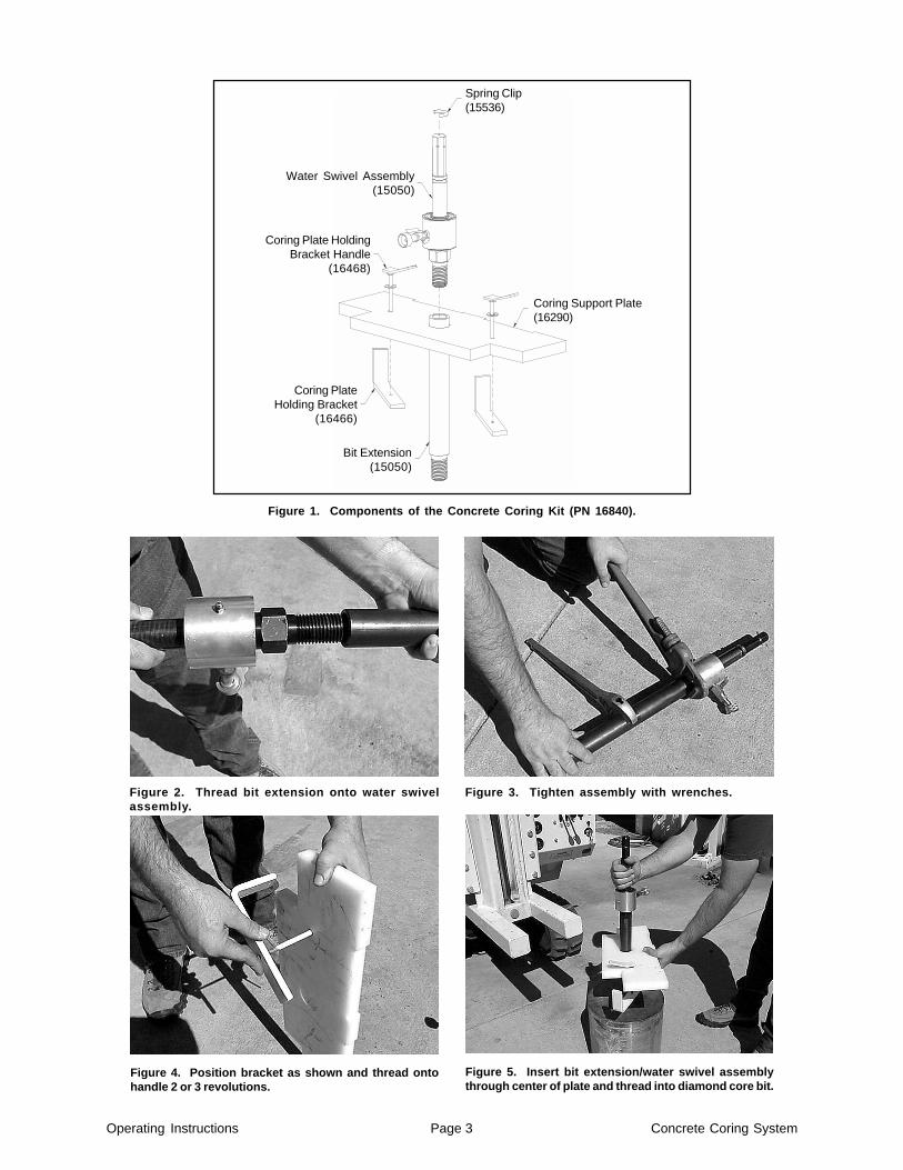
1. Thread the bit extension (PN 15050) onto the water swivel assembly (PN 15315) as shown in Figure 2.Tighten with adjustable wrenches or pipe wrenches (Fig. 3)
2. Place a 5/16-inch flat washer on each coring plate holding bracket handle (PN 16466). Insert a handlethrough each of the two small holes in the coring support plate (PN 16290).
3. Thread a coring plate holding bracket (PN 16468) onto each handle. Position the brackets as shown inFigure 4. Tighten only 2 or 3 revolutions at this time.
4. Insert the threaded end of the bit extension/water swivel assembly through the center hole in the coringsupport plate with the bracket handles toward the water swivel. Thread the extension into the top of adiamond core bit as shown in Figure 5. Tighten the connection using the adjustable wrenches and/or pipewrenches (Fig. 6).
Operating Instructions Page 3 Concrete Coring System
Figure 2. Thread bit extension onto water swivelassembly.
Figure 3. Tighten assembly with wrenches.
Figure 4. Position bracket as shown and thread ontohandle 2 or 3 revolutions.
Figure 5. Insert bit extension/water swivel assemblythrough center of plate and thread into diamond core bit.
Figure 1. Components of the Concrete Coring Kit (PN 16840).
Spring Clip(15536)
Coring Support Plate(16290)
Coring Plate HoldingBracket Handle
(16468)
Coring PlateHolding Bracket
(16466)
Bit Extension(15050)
Water Swivel Assembly(15050)

Operating Instructions Page 4 Concrete Coring System
5. For GH40-Series Hammers: Slide an anvil retainer cap assembly (GH4200) over the water swivel shaft. Installa spring clip (PN 15536) in the lower groove on the shaft using a hammer as shown in Figure 7.
For GH60 Hammers: Slide a GH60 retainer cap (PN 7617) over the water swivel shaft. Place a GH60 hexadapter (PN 14779) on the shaft such that the large hex is “up”. Install a spring clip in the upper groove onthe shaft (located on hex flats) using a hammer as shown in Figure 8.
Note: The spring clip may expand with use until it no longer fits tightly in the shaft groove. If thisoccurs, carefully squeeze the clip in a machine vise to restore the original shape.
Figure 6. Tighten bit extension to bit with wrenches. Figure 7. Install a spring clip in the lower groove ofthe water swivel shaft for GH40-Series applications.
4.0 Installation of Coring Assembly on a 5410- and 5400-Series Machine with a GH40-Series Hammer
Size limitations necessitate operating the coring assembly with the bit placed below the toes of the derrick foot toavoid equipment damage. This also allows the use of a coring support plate that clamps onto the foot to stabilizethe coring assembly during rotation.
Differences in foot dimensions require that the coring support plate be positioned differently on the Model 5410than for 5400-Series units. This section contains instructions for installing the concrete coring system on 5400-Series machines with GH40-Series hammers and the Model 5410/GH42 hammer configuration.
Note: The concrete coring system is not compatible with Geoprobe® Model 54LT and 540M machines.
1. Unfold the probe derrick leaving the foot approximately 18 inches from the ground surface. Raise the hammerapproximately halfway.
Figure 8. Install a spring clip in the upper groove ofthe water swivel shaft for GH60 applications.
Figure 9. Position support plate with end cutoutsfacing the operator on 5400-Series units.
Operating Instructions Page 5 Concrete Coring System
2. Remove the anvil and anvil retainer cap assembly from the hammer if present.
3. For 5400-Series Machines: Position the coring assembly under the hammer as shown in Figure 9. Notethat the back of the support plate is placed near the derrick and the end cutouts face the operator.
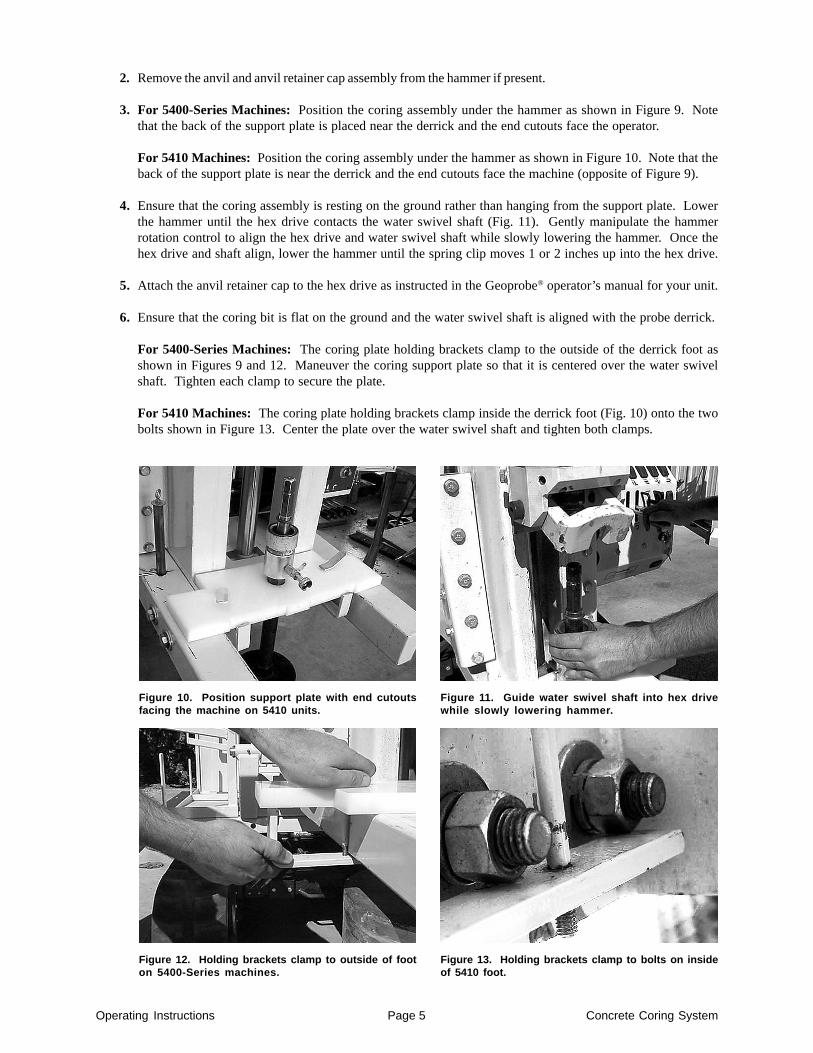
For 5410 Machines: Position the coring assembly under the hammer as shown in Figure 10. Note that theback of the support plate is near the derrick and the end cutouts face the machine (opposite of Figure 9).
4. Ensure that the coring assembly is resting on the ground rather than hanging from the support plate. Lowerthe hammer until the hex drive contacts the water swivel shaft (Fig. 11). Gently manipulate the hammerrotation control to align the hex drive and water swivel shaft while slowly lowering the hammer. Once thehex drive and shaft align, lower the hammer until the spring clip moves 1 or 2 inches up into the hex drive.
5. Attach the anvil retainer cap to the hex drive as instructed in the Geoprobe® operator’s manual for your unit.
6. Ensure that the coring bit is flat on the ground and the water swivel shaft is aligned with the probe derrick.
For 5400-Series Machines: The coring plate holding brackets clamp to the outside of the derrick foot asshown in Figures 9 and 12. Maneuver the coring support plate so that it is centered over the water swivelshaft. Tighten each clamp to secure the plate.
For 5410 Machines: The coring plate holding brackets clamp inside the derrick foot (Fig. 10) onto the twobolts shown in Figure 13. Center the plate over the water swivel shaft and tighten both clamps.
Figure 10. Position support plate with end cutoutsfacing the machine on 5410 units.
Figure 11. Guide water swivel shaft into hex drivewhile slowly lowering hammer.
Figure 12. Holding brackets clamp to outside of footon 5400-Series machines.
Figure 13. Holding brackets clamp to bolts on insideof 5410 foot.
Operating Instructions Page 6 Concrete Coring System
5.0 Installation of Coring Assembly on a 6600-Series Machine with a GH60 Hammer
Size limitations necessitate operating the coring assembly with the bit placed below the toes of the derrick foot toavoid equipment damage. This also allows the use of a coring support plate that clamps onto the foot to stabilizethe coring assembly during rotation.
1. Unfold the probe derrick leaving the foot approximately 18 inches from the ground surface. Raise the hammerapproximately halfway.
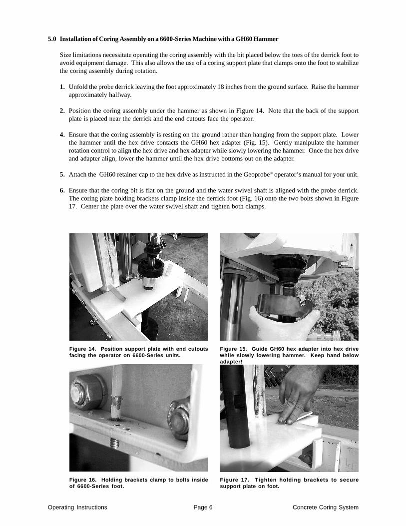
2. Position the coring assembly under the hammer as shown in Figure 14. Note that the back of the supportplate is placed near the derrick and the end cutouts face the operator.
4. Ensure that the coring assembly is resting on the ground rather than hanging from the support plate. Lowerthe hammer until the hex drive contacts the GH60 hex adapter (Fig. 15). Gently manipulate the hammerrotation control to align the hex drive and hex adapter while slowly lowering the hammer. Once the hex driveand adapter align, lower the hammer until the hex drive bottoms out on the adapter.
5. Attach the GH60 retainer cap to the hex drive as instructed in the Geoprobe® operator’s manual for your unit.
6. Ensure that the coring bit is flat on the ground and the water swivel shaft is aligned with the probe derrick.The coring plate holding brackets clamp inside the derrick foot (Fig. 16) onto the two bolts shown in Figure17. Center the plate over the water swivel shaft and tighten both clamps.
Figure 14. Position support plate with end cutoutsfacing the operator on 6600-Series units.
Figure 15. Guide GH60 hex adapter into hex drivewhile slowly lowering hammer. Keep hand belowadapter!
Figure 16. Holding brackets clamp to bolts insideof 6600-Series foot.
Figure 17. Tighten holding brackets to securesupport plate on foot.
Operating Instructions Page 7 Concrete Coring System
6.0 Water System
Water is pumped through the water swivel assembly and bit extension to lubricate and cool the bit while coring.As a secondary function, water also carries away the fine particles (grit) created as the bit cuts into the surfacematerial.
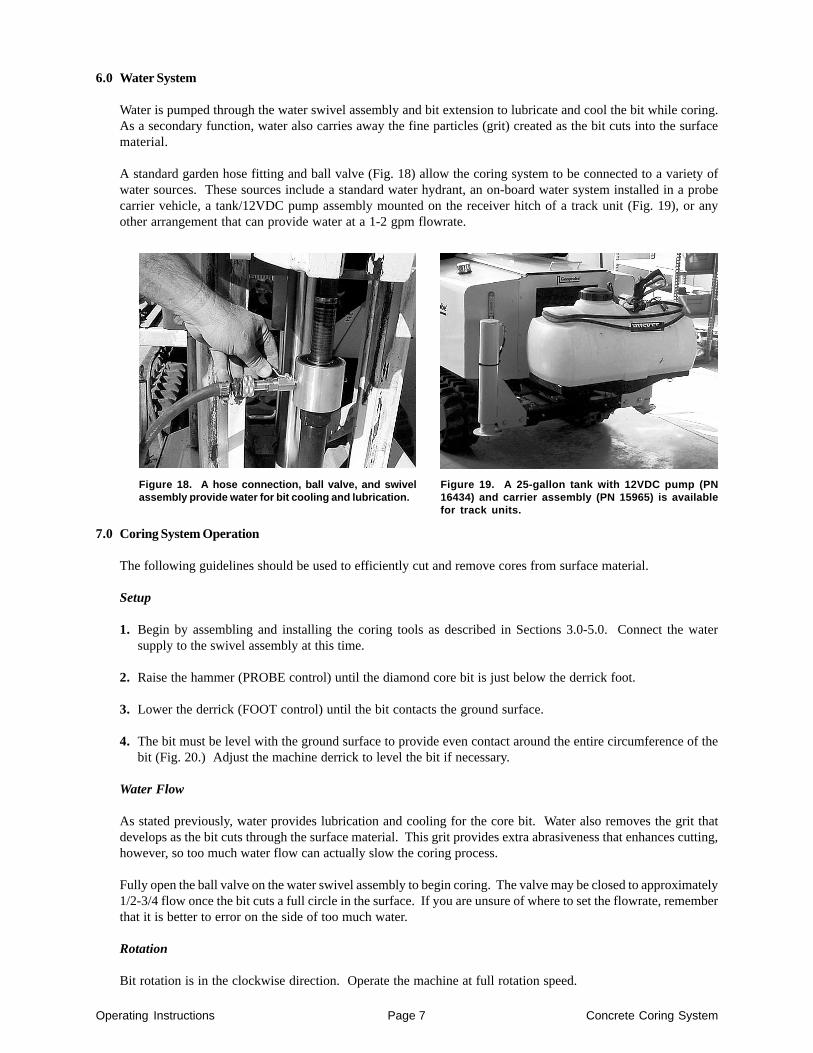
A standard garden hose fitting and ball valve (Fig. 18) allow the coring system to be connected to a variety ofwater sources. These sources include a standard water hydrant, an on-board water system installed in a probecarrier vehicle, a tank/12VDC pump assembly mounted on the receiver hitch of a track unit (Fig. 19), or anyother arrangement that can provide water at a 1-2 gpm flowrate.
Figure 18. A hose connection, ball valve, and swivelassembly provide water for bit cooling and lubrication.
Figure 19. A 25-gallon tank with 12VDC pump (PN16434) and carrier assembly (PN 15965) is availablefor track units.
7.0 Coring System Operation
The following guidelines should be used to efficiently cut and remove cores from surface material.
Setup
1. Begin by assembling and installing the coring tools as described in Sections 3.0-5.0. Connect the watersupply to the swivel assembly at this time.
2. Raise the hammer (PROBE control) until the diamond core bit is just below the derrick foot.
3. Lower the derrick (FOOT control) until the bit contacts the ground surface.
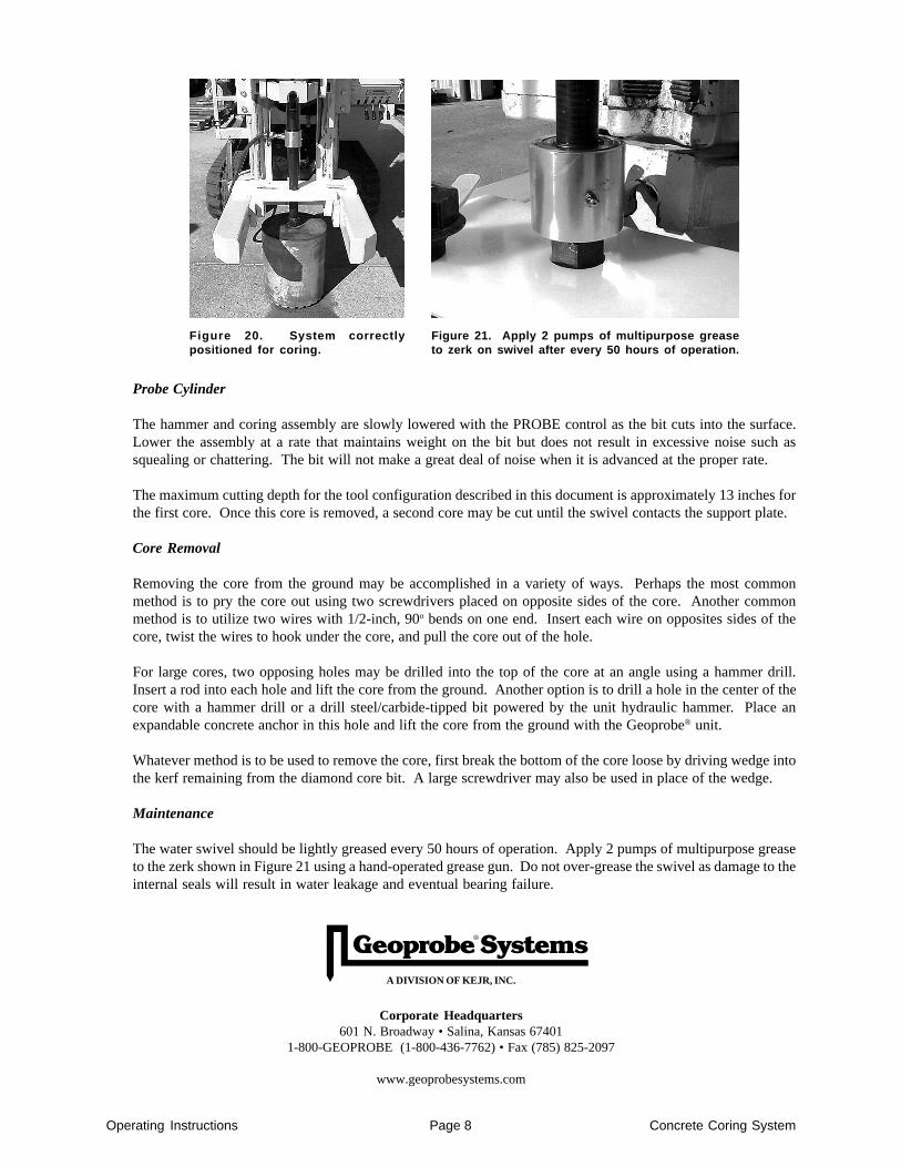
4. The bit must be level with the ground surface to provide even contact around the entire circumference of thebit (Fig. 20.) Adjust the machine derrick to level the bit if necessary.
Water Flow
As stated previously, water provides lubrication and cooling for the core bit. Water also removes the grit thatdevelops as the bit cuts through the surface material. This grit provides extra abrasiveness that enhances cutting,however, so too much water flow can actually slow the coring process.
Fully open the ball valve on the water swivel assembly to begin coring. The valve may be closed to approximately1/2-3/4 flow once the bit cuts a full circle in the surface. If you are unsure of where to set the flowrate, rememberthat it is better to error on the side of too much water.
Rotation
Bit rotation is in the clockwise direction. Operate the machine at full rotation speed.
Operating Instructions Page 8 Concrete Coring System
A DIVISION OF KEJR, INC.
Corporate Headquarters601 N. Broadway • Salina, Kansas 67401
1-800-GEOPROBE (1-800-436-7762) • Fax (785) 825-2097
www.geoprobesystems.com
Probe Cylinder
The hammer and coring assembly are slowly lowered with the PROBE control as the bit cuts into the surface.Lower the assembly at a rate that maintains weight on the bit but does not result in excessive noise such assquealing or chattering. The bit will not make a great deal of noise when it is advanced at the proper rate.
The maximum cutting depth for the tool configuration described in this document is approximately 13 inches forthe first core. Once this core is removed, a second core may be cut until the swivel contacts the support plate.
Core Removal
Removing the core from the ground may be accomplished in a variety of ways. Perhaps the most commonmethod is to pry the core out using two screwdrivers placed on opposite sides of the core. Another commonmethod is to utilize two wires with 1/2-inch, 90o bends on one end. Insert each wire on opposites sides of thecore, twist the wires to hook under the core, and pull the core out of the hole.
For large cores, two opposing holes may be drilled into the top of the core at an angle using a hammer drill.Insert a rod into each hole and lift the core from the ground. Another option is to drill a hole in the center of thecore with a hammer drill or a drill steel/carbide-tipped bit powered by the unit hydraulic hammer. Place anexpandable concrete anchor in this hole and lift the core from the ground with the Geoprobe® unit.
Whatever method is to be used to remove the core, first break the bottom of the core loose by driving wedge intothe kerf remaining from the diamond core bit. A large screwdriver may also be used in place of the wedge.
Maintenance
The water swivel should be lightly greased every 50 hours of operation. Apply 2 pumps of multipurpose greaseto the zerk shown in Figure 21 using a hand-operated grease gun. Do not over-grease the swivel as damage to theinternal seals will result in water leakage and eventual bearing failure.
Figure 20. System correctlypositioned for coring.
Figure 21. Apply 2 pumps of multipurpose greaseto zerk on swivel after every 50 hours of operation.