2-Post Vehicle Lift
53
sss1. Introduction 2-Post Vehicle Lift SGL35 O P E R A T I N G a n d M A I N T E N A N C E M A N U A L © Rotary Lift, 03/2013 ● 117592 ● Rev. C
Transcript of 2-Post Vehicle Lift
sss1. Introduction
2-Post Vehicle Lift SGL35
OOPP EE RR AA TT II NNGG aa nndd
MMAA II NN TT EE NN AA NN CC EE
MMAA NNUU AA LL
© Rotary Lift, 03/2013 ● 117592 ● Rev. C


Reg-Nr. 042_2006/42/EG
EC Declaration of Conformity according to EC directive 2006/42/EC on machinery (Annex II A)
Name and address of the manufacturer: BlitzRotary GmbH Hüfinger Str.55 78199 Bräunlingen, Germany This declaration relates exclusively to the machinery in the state in which it was placed on the market, and excludes components which are added and/or operations carried out subsequently by the final user. The declaration is no more valid, if the product is modified without agreement. Herewith we declare, that the machinery described below Product denomination: 2-post vehicle lift model / type: SGL35 Capacity 3500 kg machinery / serial number: ……………….. Year of manufacture: 20… Complies with all essential requirements of the Machinery Directive2006/42/EC In addition the partly completed machinery is in conformity with the EC Directives 2004/108/EC relating to electromagnetic compatibility and 2006/95/EC relating to electrical equipment (Protection objectives have been met in accordance with Annex I No. 1.5.1 of the Machinery Directive 2006/42/EC).
Harmonised Standards used: EN 1493: 2010 Vehicle lifts EN ISO 12100-1 : 2003 Safety of Machinery- Basic concepts EN ISO 12100-2 : 2003 Safety of Machinery- Basic concepts EN 60204-1:2006+7/2007 Electrical equipment of machines EN 349:1993+A1:2008 Safety of machinery - Minimum gaps EN ISO 13850:2008 Safety of machinery – Emergency stop EN ISO 14121-1:2007 Safety of machinery - Risk assessment
Other technical standards and specifications used: BGG 945 inspection of vehicle lifts BGR 500 management of working appliances BGV A3 Accident prevention regulation of electric facilities and equipment
The person authorised to compile the relevant technical documentation: Herr Pohl; Hüfinger Str. 55; 78199 Bräunlingen Place : Bräunlingen Date : 19.03.2013
______________________ Frank Scherer Managing Director


1. Introduction
1 117592 ● 03/2013
Contents
1. Introduction .................................................. 2 1.1 About this operating manual ................. 2 1.2 Important information for the machine
operator ................................................. 2 1.3 Specialist for safety related work .......... 3 1.4 In-house accident, health & safety and
environmental information ..................... 3 1.5 Warning and information symbols ......... 3
2. Intended use ................................................ 4 2.1 General .................................................. 4 2.2 Incorrect use .......................................... 4
3. The lift ........................................................... 4 3.1 Functionality .......................................... 4 3.2 System overview ................................... 5 3.3 Technical data ....................................... 6 3.4 Identification of lift.................................. 6 3.5 Permitted weight distribution ................. 7 3.6 Safety mechanisms ............................... 8 3.7 Control box ............................................ 9
4. Safety regulations ..................................... 10 4.1 General operation................................ 10 4.2 Operational safety, breakdowns .......... 10 4.3 Picking up loads .................................. 10 4.4 Up /down ............................................. 10 4.5 Installation, maintenance, servicing .... 10
5. Operation .................................................... 11 5.1 Emergency stop .................................. 11 5.2 Before use ........................................... 11 5.3 Switching on the equipment ................ 11 5.4 Driving the vehicle onto the lift ............ 11 5.5 Up / down ............................................ 11 5.6 Using the lift ......................................... 12 5.7 Before lowering the lift ......................... 12 5.8 Driving the vehicle from the lift ............ 12 5.9 Switch off the system .......................... 13
6. Action in the event of a fault .................... 14 6.1 Operator troubleshooting .................... 14 6.2 Troubleshooting for competent persons15 6.3 Emergency lowering ............................ 17
6.4 Recommissioning the lift after incorrect alignment of the slider blocks .............. 18
7. Maintenance ............................................... 19 7.1 Maintenance staff qualification ............ 19 7.2 Safety regulations ................................ 19 7.3 Maintenance schedule ......................... 19 7.4 Cleaning ............................................... 20 7.5 Check the hydraulic oil level ................ 20 7.6 Approved hydraulic oils ........................ 20 7.7 Check the hydraulic component seals . 20 7.8 Inspect and adjust the synchronisation
cables ................................................... 20 7.9 Carry out a function test ....................... 21
8. Repairs ........................................................ 21
9. Safety inspections ..................................... 21
10. Transport, storage ..................................... 21 10.1 Storage ................................................ 21 10.2 Transport .............................................. 21 10.3 Unpacking ............................................ 22
11. Installation .................................................. 23 11.1 Installation guidelines .......................... 23 11.2 Mechanical installation ......................... 24 11.3 Hydraulic installation ............................ 26 11.4 Electrical connection ............................ 26 11.5 Final assembly of the mechanical unit . 27
12. Commissioning .......................................... 30
13. Disassembly ............................................... 32
14. Disposal ...................................................... 32 14.1 Packaging ............................................ 32 14.2 Environmental procedures for disposal32 14.3 Metals / Electronic waste ..................... 32
ANNEX ................................................................. 33
Diagrams, Spare parts lists, supplementary instructions
Electrical Circuit diagram
Hydraulic diagram
Spare parts lists
Hydraulic power unit

1. Introduction
2 117592 ● 03/2013
1. Introduction
1.1 About this operating manual
The post lift conforms to state of the art technology and complies with the applicable occupational health & safety and accident prevention regulations. Notwithstanding, improper use or use other than that which is intended may result in a risk of fatal or physical injury to the user or third parties and may also result in damage to property.
It is therefore imperative that the relevant people carefully read and understand this operating manual.
Read the instructions carefully to prevent incorrect use, potential hazards and damage. The post lift should always be operated according to regulations.
Please note the following:
The operating manual must be kept close to the lift and be easily accessible for all users.
Make sure that you have read and understood Chapter 4, Safety Instructions and also the operating instructions on the machine.
We assume no liability for damage and operational breakdowns which may occur as a result of non-compliance with the instructions contained within this operating manual.
Installation and commissioning of the lifts is described in detail in Chapters 11 to 13. Installation may only be carried out by authorised installation specialists (trained by the manufacturer) and qualified electricians.
If you should run into difficulties please contact a specialist, our customer service.
Illustrations may differ from the supplied version of the machine. Functions or processes to be carried out remain the same.
1.2 Important information for the machine operator
The operating manual contains important information for safe operation and for the functional reliability of the lift.
The signed form “Installation record“ must be sent to the manufacturer to verify the installation of the lift.
The “Inspection logbook“ contains forms for verifying the initial, regular, and unscheduled safety inspections. Use the forms to record the inspections and add the completed forms to the inspection logbook.
Design modifications must be entered in the “Machine master data sheet“.
The machine operator is responsible for ensuring that the lift is always operated in a safe manner and the following requirements are met or regularly carried out.
The operators must be qualified through specialist training and experience.
The operator must be familiar with the applicable occupational health & safety and accident prevention regulations and be instructed and trained to operate the lift.
The operator must have read and understood the safety regulations chapter and verified this with his signature.
If several people work on the post lift, a foreman must be appointed.
The post lift may only be operated in technically sound condition with regard to safety.
Maintenance and servicing must be performed regularly according to the defined schedule.
Safety inspections must be conducted regularly, and at least once annually in accordance with chapter 9.
The inspection logbook must be kept up-to-date.
This operating manual as well as the annexed instructions must always be kept with the lift. This also applies if the lift is sold or re-installed at a new location.
For safety reasons, unauthorised modifications or alterations to the lift are not permitted. In case of an unauthorised modification, the operating permit is cancelled, and the Declaration of Conformity becomes null and void.
Disclaimer: We assume no responsibility for printing errors, mistakes and technical changes. The brands and trade marks mentioned in this document refer to their owners or the products thereof. This is the original manual in German.

1. Introduction
3 117592 ● 03/2013
1.3 Specialist for safety related work
The post lift must be inspected after commissioning and at regular intervals but at least annually. as well as after the replacement of safety-related parts during maintenance work.
Safety-related work and safety inspections on the lift may only be carried out by people trained to do so. These people are generally known as certified experts and competent persons.
Certified experts are persons who may inspect and assess lifts (freelance specialist engineers, TÜV certified experts), based on their training and experience. They are familiar with the relevant occupational health & safety and accident prevention regulations.
Competent persons (skilled people) are persons who have sufficient knowledge and experience of lift systems. They have attended a special training course at the lift manufacturer. Competent persons are customer service fitters for the manufacturer or authorised dealer.
1.4 In-house accident, health & safety and environmental information
This operating manual does not contain information and instructions with actions in the event of accidents and health risks.
The in-house operating instruction must be supplied by the operator of the lift.
1.5 Warning and information symbols
Warnings are identified by the following symbols, depending on the hazard classification.
Be especially aware of safety and hazards when working in situations identified by warning symbols. Comply with the occupational health & safety and accident prevention regulations which are applicable in your country.
Risk of death or injury Direct threat to life and health of
people. Non-compliance may lead to death or serious injury.
Risk of death or injury Potential risk to life and health of people. Non-compliance may lead to serious or critical injury.
Risk of injury Potentially hazardous situation.
Non-compliance may lead to minor or moderate injury.
Damage to property
Potentially hazardous situation. Non-compliance may lead to damage to property.
Other Symbols
INFO-Symbol Useful information and tips.
Bullet point: For lists with key information on the respective subject.
1. Action: Carry out the detailed steps in order.
Action symbol Carry out the detailed steps in order.
DANGER
CAUTION
ATTENTION
i
WARNING

2. Intended use
4 117592 ● 03/2013
2. Intended use
2.1 General
WARNING
Risk of injury!
To prevent injury to persons or property, the lift should only be operated by trained operators.
After reading this manual, become familiar with operating the lift by conducting several trial runs before loading a vehicle onto the lift.
The lift is designed to raise and lower cars and delivery vehicles for repair, maintenance, and cleaning in a normal workshop environment.
The lift may only be used according to regulations, in a fully functional condition according to the technical data in chapter 3.3.
The max load capacity of the whole lift is 3500 kg and may not be exceeded.
Operators may stand under the raised load.
DANGER
Risk of injury if used incorrectly.
ALWAYS raise the vehicle with all four (4) adapters! Never lift only one end, one corner or one side of the vehicle.
2.2 Incorrect use
Incorrect use presents a residual risk to the life and health of the people working in the lift zone.
The manufacturer assumes no liability for damage resulting from use other than the intended purpose and misconduct.
The following is prohibited:
Climbing onto or riding on the load or pick-up equipment.
Loitering under the load when raising or lowering.
Raising vehicles loaded with hazardous substances.
Installing the lift in areas at risk from explosion.
Using the lift for washing vehicles and under any other conditions not expressly specified in the operating manual,
The manufacturer assumes no liability for damage of any kind which arises through incorrect, erroneous, or unreasonable use.
3. The lift
3.1 Functionality
The lift is designed to raise vehicles to the optimum height for maintenance, cleaning, or repair work.
The lift is operated by pressing buttons on the control unit which is attached to one of the posts.
The vehicle is raised and lowered in jog mode.
Steel cables ensure that the vehicle is raised horizontally.

3. The lift
5 117592 ● 03/2013
3.2 System overview
Figure 1: Example of a post lift
1 Primary column
2 Secondary column
3 Drive-through ramp
4 Control unit
5 Hydraulic unit
6 Column base plate
7 Arm
8 Adapter
9 Slide
10 Base plate support (optional extra)
11 Lever for latch mechanism
12 Latch mechanism cover
13 Hole for anchor bolts
14 Cover plate
1

3. The lift
6 117592 ● 03/2013
3.3 Technical data
SGL35
Load capacity / Lift cylinder [kg] 3500
A Rise [mm] 1828
B Overall height [mm] 3160
C Overall width [mm] 3320
D Drive-through clearance [mm] 2388
F Reach front arm min. [mm] 600
G Reach front arm max. [mm] 1280
H Reach rear arm min [mm] 600
I Reach rear arm max. [mm] 1280
J Adapter height min. [mm] 110
K Adapter height max. [mm] 166
L Inside columns [mm] 2688
M Motor [kW] 2.2
Electrical connection (3 phases)
400 V 50 Hz
Rise time [sec] 40
Required ceiling height [mm] 3170
2
3.4 Identification of lift
The customer service department of your authorised dealer can react quicker to your maintenance queries if you specify the lift, serial number, and any possible accessories. The information below is given on the information plates: BlitzRotary GmbH Hüfinger Str.55 78199 Bräunlingen Deutschland Telephone: +49 771 9233 0 Fax: +49 771 9233 10 Model SGL 35 Model year 20__ Serial number _____________ Load capacity (kg) 3500 Power supply (V) 230 / 400 Power consumption (kW) 2.3 Actuating power (kW) 2.2 Phases 3 + PE Frequency (Hz) 50 / 60 Specified hydraulic pressure (bar) 205

3. The lift
7 117592 ● 03/2013
3.5 Permitted weight distribution
Figure 3: Vehicle centre of gravity
The weight distribution on the adapters is reversible for this post lift: The heavy load can either be placed on the long or the short arms P1 (1/3) - P2 (2/3) of the maximum load.
Figure 3: Minimum distance between two adapters
Not less than 1000 mm
If the distance is less, the load capacity of the lift will be reduced
The weight distribution must match the guidelines specified in this chapter. We therefore recommend distributing the weight as centrally as possible in relation to the axis of the posts.
3
4
i

3. The lift
8 117592 ● 03/2013
3.6 Safety mechanisms
Figures 5 ... 9: Safety mechanisms
Electrical Emergency stop button on the control unit
(Figure 5)
Broken chain and slack chain switch (lifting chain): consists of a micro switch, which is fitted in each column at the bottom. This module permits any movement of the lift to be halted if a chain is broken or unusually slack. (Figure 6)
Hydraulic Broken line switch: consists of a valve in a
hydraulic cylinder. This valve is designed to limit the lowering rate if the hydraulic line fails (breaks). It is set so that the lowering rate does not exceed the nominal rate by more than 1.5 x.
Mechanical Mechanical latching system: consists essentially
of a spring-loaded latch which is fitted on each column, as well as a bar with notches on each slider block. This latch and bar assembly stops the lift from accidentally dropping in the event of a leak in the hydraulic system or breaks in the system components (Figure 7)
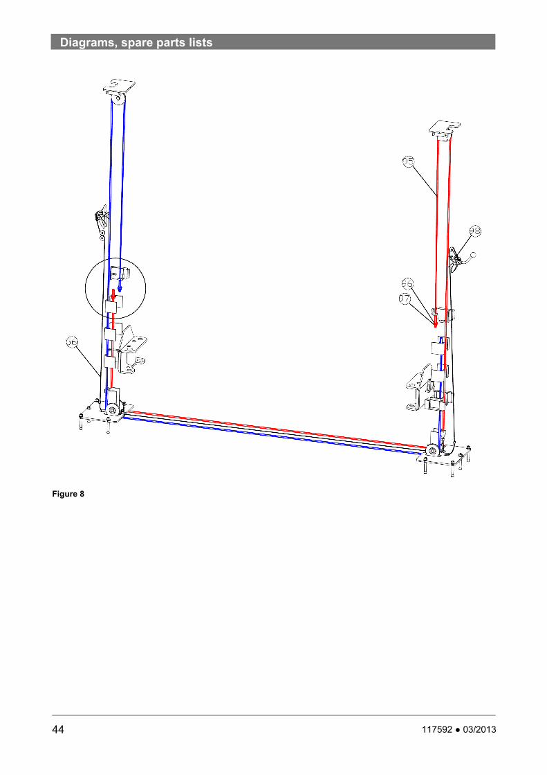
Arm restraints: consist of a ring gear on the end of the arm which engages the pinion of the lift slide. This assembly is activated as soon as the slide leaves its lowest point to prevent the arms from slewing. (Figure 8)
Mechanical synchronisation control: consists of two synchronisation cables which connect the slider blocks to each other. The cables prevent incorrect alignment of one slider in relation to the other slider if the weight is unevenly balanced crosswise. (Figure 9)
Ergonomics Foot protection: metal plates on both sides of
the base plate of both columns and a metal baffle plate in the outside of the arms which prevent a foot becoming trapped under the slider block or arm(s).
5
6
7

3. The lift
9 117592 ● 03/2013
8
9
3.7 Control box
(see figure 11)
1 Main switch, emergency stop To connect the lift to the mains supply, turn the switch to ”1", to disconnect from the power supply turn it to ”0".
2 Control box key Opens the control box for maintenance purposes.
3 Up button Press this button to actuate the hydraulic power unit and raise the slider block. This works on the dead man’s switch principle, meaning that when the button is released, raising of the lift is halted immediately.
4 Down button When this button is pressed and the latching system lever is activated at the same time (s. Figure 7), the slider block is lowered. This works on the dead man’s switch principle, meaning that when the button is released, lowering of the lift is halted immediately. The system is also locked by the latching mechanism. Before lowering, the latching mechanism must first be released. If the lever cannot be released, the latch has engaged. The lift must first be raised a little to finally release the system. Only then can you lower the lift.
11

4. Safety regulations
10 117592 ● 03/2013
4. Safety regulations Comply with the following regulations!
4.1 General operation
Only operate the lift if you have read and understood this operating manual. Also refer to the brief operating instructions on the lift.
The total permitted weight is 3,500 kg .
Only persons who are 18 years old, are trained in operating the lift, and have signed the handover sheet are permitted to operate the lift.
Vehicles with low ground clearance or with optional extras should be checked beforehand. They can only be lifted if no damage can be caused.
Work on the lift may only be carried out if the main switch is turned off and locked.
Do not: ● Carry people on the lift. ● Climb onto the lift or the load. ● Ride on the lift with equipment.
Emergency lowering of a vehicle may be done only by competent persons.
Switch off equipment when not in use.
Do not use the lift in proximity to a potentially combustible or flammable atmosphere.
4.2 Operational safety, breakdowns
The operational safety of the lift must be inspected regularly.
If breakdowns occur or if there are missing safety components, shut down the lift immediately. Inform the supervisor or customer service.
4.3 Picking up loads
Before lifting with the arms, check the pick-up points on the vehicle for load capacity, corrosion, damage, and modifications.
Only lift vehicles at the points approved by the manufacturer.
Do not carry out any work on a raised vehicle which may affect the stability of the pick-up points.
4.4 Up /down
Only operate the lift if it poses no danger to people.
During the raising and lowering process, no-one should loiter within range of the moving load and the pick-up points.
Briefly raise the lift to check that the vehicle pick-up points are secure. The latches must be properly engaged. Only then lift the vehicle to the desired height. The lift and the vehicle may otherwise become dangerously unstable.
The area within range of moving loads and pick-up points must be free of obstacles.
4.5 Installation, maintenance, servicing
Installation, maintenance, and servicing work may only be carried out by trained and authorised specialists, with the system switched off and made safe.
Electrical work may only be carried out by qualified electricians.
Only specialist staff with specialist knowledge and experience may work on hydraulic equipment.
Repairs on the safety equipment of the lift may only be carried out by competent persons.
Follow the maintenance schedule, document maintenance work.
Only use OEM parts.
Following design modifications or repair work on safety relevant parts, the lift must be inspected by a certified expert.

5. Operation
11 117592 ● 03/2013
5. Operation
DANGER
Risk of injury if an incorrect procedure is followed during breakdowns.
If there are indications of faults such as unusual noise or leaks, shut down the lift immediately, secure it, and inform the supervisor.
5.1 Emergency stop
To prevent any movement of the lift in an emergency (malfunction or defect), set the main switch to ”0" and lock it with the key switch.
5.2 Before use
DANGER
Risk of injury if an incorrect procedure is followed before use
No one may loiter under the vehicle when the lift is moving, clamber onto the lift, or climb into the car. The movement of the slider block and the arms must not be hampered by objects (e.g. tools), before they have reached their end position.
Inspect the lift - see ”Inspection and maintenance instructions for operators". Never activate the lift if it is showing a malfunction or damaged parts.
Before the vehicle is placed on the lift, it must be fully lowered and everyone must move away from the work area.
If problems occur, set the main switch to ”0“. The lift may only be inspected by authorised and qualified staff. Before all maintenance or repair work, lock the main switch with the key switch and if necessary, disconnect the lift from the power supply.
Do NOT use the lift as a crane or jack for other lifting mechanisms!
5.3 Switching on the equipment
To connect the control unit to the power supply, set the main switch to ”1".
5.4 Driving the vehicle onto the lift
Unauthorised or untrained persons may NOT operate the lift and may NOT lift the vehicle.
Do NOT drive against or over the arms
Do NOT overload the lift: Refer to the load capacity plate on the lift
Refer to the weight distribution details in the ”Area of use" chapter. Never exceed the figures in this chapter in order not to expose the operator to danger.
Make sure that the vehicle is centred according to the longitudinal axis of the lift and that the pick-up points of the vehicle chassis are correctly positioned in relation to the adapters.
Make sure that the arms do not directly touch the vehicle chassis. Before lifting, check again that all adapters are correctly positioned below the pick-up points.
Check that the arm restraints are properly engaged before lifting the vehicle.
Make sure that no danger arises from lifting the load, and after lifting the load for a few centimetres, check that the vehicle is correctly positioned and secure.
It is essential that the vehicle is lifted at the points indicated by the manufacturer for this purpose and only accessories supplied by the manufacturer of the lift.
When raising and lowering, ensure that the motion of the lift is smooth and does not chatter and that the load is always stable. If a vehicle is unstable or the operation of the lift does not appear normal, halt operation of the lift immediately. If possible, lower the lift again with extreme care. If necessary, check and correct the vehicle position. If the vehicle continues to be unstable, set the main switch to ”0“ and contact the maintenance technician at your authorised dealer.
5.5 Up / down
The lift must be lowered and raised steadily, so that the load does not shift.
If the vehicle does not remain stable, halt all lift movement immediately.
Then turn the main switch to ”0“ and lock it.
i
i
i

5. Operation
12 117592 ● 03/2013
The vehicle must now be lowered by an authorised competent person.
ONLY use adapter extensions from the lift manufacturer. DO NOT use wood or concrete blocks or other improvised extensions.
Check the condition of the pick-up points on the vehicle. These should be free of grease, oil and dirt. Arms swing under the vehicle and position the adapter on the pick-up points recommended by the vehicle manufacturer (Fig. 4). Bring the adapter to the corresponding height to stop the car straight and properly balanced. When raising and lowering, monitor the lifted vehicle constantly. If the lift is not synchronised, pause the movement and determine the cause. Monitor the tension of the synchronisation cables through the inspection window in the plate frame, and if there are irregularities, shut down the lift and contact the service department.
Raising
1. Press the Up button. Raise the vehicle slightly.
2. Check that the vehicle pick-up points are secure.
3. Press the Up button. Raise the vehicle to the desired height.
4. Make sure that each pinion engages the ring gear as soon as the slider block loses contact with the floor.
5. If one of the pinions does not engage the ring gear, the bolt with the pull ring at the top can be seen to protrude further than normal at the top on the guide shaft of the pinion (Fig. 8, in normal position). In this case, lower the slider block and re-position the problematic arm.
6. Release the SAFETY lever and the Up button as soon as the working height has been reached.
7. When the required height has been reached, the lift can engage the safety latch.
8. Set the main switch to ”0", as soon as the necessary working height has been reached.
Down
1. Connect the control unit to the power supply and set the main switch to “1“, pull the SAFETY
lever and push the DOWN button to lower the lift to the required level.
2. If you cannot pull the lever down, the latching mechanism has engaged. Press the UP and DOWN buttons at the same time so that the slider block rises and the lever is released. Then lower the vehicle.
The latch mechanism, the lever, and the "Up" and "Down" switches are dead man’s switches. The lift is raised and lowered as long as the buttons and the lever are engaged.
3. Set the main switch to “0“.
5.6 Using the lift
Prevent extreme vibrations from the vehicle whilst it is positioned on the lift
If required, always use safety stands as stabilisers when removing or fitting heavy components (i.e. engines, gearboxes etc). Use 4 safety stands
When lowering, stay outside the range of the lift. Do not stand in the lowering zone.
Wear protective goggles when working underneath the vehicle
If necessary, also use support straps to stabilise the vehicle on the arm when disassembling parts.
5.7 Before lowering the lift
Remove all tools and other objects from the lift zone.
Ensure that no-one is in the lift zone.
Ensure that there are no people or objects in the drive-off zone before driving the vehicle from the lift.
5.8 Driving the vehicle from the lift
1. Secure the vehicle against rolling.
2. Ensure that the arms are in their outermost position on full drive-thru position before driving the vehicle from the lift.
i
i
i
i
i
i

5. Operation
13 117592 ● 03/2013
3. Drive the vehicle away from the lift.
5.9 Switch off the system
1. Set the main switch to “0".

6. Action in the event of a fault
14 117592 ● 03/2013
6. Action in the event of a fault Check the lift with reference to the potential
causes of the faults listed below.
If the fault cannot be rectified as per the list of causes, inform the customer service at your dealership.
6.1 Operator troubleshooting
Cannot switch the lift on
Cause: 1. No power supply. 2. Main switch not activated. Remedy: 1. Switch on the power supply. 2. Activate the main switch.
Motor does not run.
Cause: 1. Fuse or circuit breaker burnt out. Remedy: 1. Replace the burnt fuse or put the circuit breaker back. 2. Contact the service staff for support. The motor runs and raises the unloaded lift – but not with the vehicle.
Cause: 1. Lift overloaded. Remedy: 1. Check the weight of the vehicle on the lift. 2. Contact the service staff for support Oil leaks
Cause: 1. Hydraulic fittings loose 2. Hydraulic line broken or faulty fitting Remedy: 1. Tighten the hydraulic fitting 2. Replace the hydraulic line or fitting. 3. Contact the service staff for support Lift does not react to controls or stops during operation.
Cause: 1. No connection to power supply. 2. Power supply disconnected. 3. Fuse damaged / burnt out. 4. Thermal protection reacted. 5. Transformer damaged.
6. Broken chain switch or the lifting chain has reacted to unusual tensioning of the lifting chain. Remedy: 1. Connect the control unit to the power supply. 2. Check the power supply. 3. Replace the fuses. 4. Wait until the thermal protection has cooled and continue operation. 5. Replace the transformer. 6. Make sure that there are no obstacles blocking the travel of the slider blocks. If necessary, tighten the synchronisation cables or lifting chains. 7. Contact the service staff for support
12
The lift starts when the UP button and the SAFETY lever are activated at the same time, but then stops while the motor continues to run.
Cause: 1. Oil level too low. 2. Load too heavy. 3. Hydraulic release valve incorrectly set. 4. Hydraulic solenoid opened, dirty or faulty. 5. Hydraulic pump or check valve is faulty. Remedy: 1. Check the oil level. 2. Check the load. 3. Check the hydraulic pressure (Fig. 12). 4. Close, clean, or replace the solenoid valve. 5. Replace the hydraulic pump or the check valve. 6. Contact the service staff for support When the DOWN button and the SAFETY lever are activated at the same time, the lift does not lower.
Cause: 1. The slider blocks have not been sufficiently raised before lowering. 2. The latch control cable is slack or broken. Remedy: 1. Press the UP and the DOWN button to disengage the mechanical safety latches. 2. Remove the two covers over the mechanical safety latches, operate the hydraulic pump,

6. Action in the event of a fault
15 117592 ● 03/2013
manually disengage the latches, hold them in this position with wedges, lower the lift, then remove the wedges. Correct the cable tension or replace the cable. Replace the covers. 3. Contact service staff for support The motor runs but the lift does not react when the UP button and SAFETY lever are activated at the same time. Cause: 1. The power supply phases are inverted. 2. Hydraulic solenoid valve opened, dirty or faulty. 3. Hydraulic pump or check valve is faulty. Remedy: 1. Change the connection to the power supply. 2. Close, clean or replace the solenoid valve. 3. Replace the hydraulic pump or check valve. 4. Contact service staff for support The lift rises slowly or oil leaks from the inlet deaerator cap. Cause: 1. see counter measures Remedy: 1. Contact service staff for support The lift rises unevenly. Cause: 1. see counter measures Remedy: 1. Contact service staff for support The anchors are not stable. Cause: 1. see counter measures Remedy: 1. Contact service staff for support The locking latches do not engage. Cause: 1. see counter measures Remedy: 1. Contact service staff for support Locking latches do not disengage. Cause: 1. see counter measures Remedy: 1. Contact service staff for support
6.2 Troubleshooting for competent persons
The motor does not run.
Cause: 1. Fuse or circuit breaker burnt out. 2. Incorrect power supply to the motor. 3. Cable connections faulty/loose. 4. Motor UP switch burnt out. 5. Motor windings burnt out. Remedy: 1. Replace the fuse or reset the circuit breaker. 2. Provide the correct power supply to the motor. 3. Repair and isolate all connections. 4. Replace the main switch/control buttons. 5. Replace the motor. The motor runs but the lift does not rise
Cause: 1. The lift is overloaded. 2. The motor is being operated on very low voltage. 3. Deposits in the parachute valve. 4. The pump is sucking in air. 5. The intake fitting has separated from the pump. 6. The oil level is low 7. The release valve is incorrectly set. 8. The lowering valve is open. Remedy: 1. Check the vehicle weight and/or the balance of
the vehicle on the lift. 2. Provide the correct power supply to the motor. 3. Clean the lowering valve. 4. Tighten the coupling on the intake line. 5. Replace the fittings. 6. Fill the tank to the correct level with ISOVG32
hydraulic oil or Dexron III ATF. 7. Replace the release valve. 8. Repair/replace the lowering valve The lift lowers slowly.
Cause: 1. Deposits in the check valve set. 2. Deposits in the lowering valve set 3. There are oil leaks. Remedy: 1. Clean the check valve. 2. Clean the lowering valve. 3. Repair the external leak. The lift rises slowly or oil leaks from the inlet deaerator cap.
Cause: 1. Air has mixed with the oil. 2. Air is being taken in with the oil. 3. The oil return line is loose. Remedy: 1. Change oil, Dexron II ATF or ISOVG32 hydraulic
oil. 2. Tighten all couplings.

6. Action in the event of a fault
16 117592 ● 03/2013
3. Repair the external leak.
The lift rises unevenly.
Cause: 1. The synchronisation cables are offset. 2. The lift is installed on an uneven foundation. Remedy: 1. Adjust the synchronisation cables to correct the
tension. 2. Adjust the lift so that the columns are at the
same height, (use shims no higher than 13 mm).
The anchoring bolt is not secure.
Cause: 1. The holes are too large. 2. The depth of the foundation or the concrete
quality is inadequate. Remedy: 1. Move the lift and use a new drill to drill holes.
The correct anchoring methods and the minimum installation requirements are described in the installation instructions.
2. Lay a new foundation slab in the lift zone as per the requirements.
The lift does not rise completely or the lifting process is erratic.
Cause: 1. Air in hydraulic lines or cylinders. 2. The oil level is low. Remedy: 1. Start the system and raise and lower the slider
block several times. Lower the lift to the bottom position and refill the drive unit as in step 2.
2. Lower the lift to the bottom position. Fill the tank with ISO VG32 hydraulic oil or Dexron III ATF to at least the MIN mark.
The locking latches do not engage.
Cause: 1. The latch mechanism shafts are oxidised. Remedy: 1. Remove the covers and lubricate the latch
mechanism. Push the latch release handle several times so that the shaft is coated with oil.
The locking latches do not disengage.
Cause: 1. The actuator cable is broken. 2. The Bowden cable mounting is loose.
3. The cable is loose. Remedy: 1. Replace the cable. 2. Check and repair the Bowden cable and its
mounting. 3. Check and correct the cable run, tension the
cable.
6. Action in the event of a fault
17 117592 ● 03/2013
6.3 Emergency lowering
Only competent persons may carry out emergency lowering of the vehicle.
DANGER
Danger of electrocution when working on an open control unit.
Only trained electricians may work on open control units.
Never touch live components.
Emergency lowering during a power failure
1. If possible, wait until the end of the power failure.
2. Then lower the lift as normal.
If no emergency power supply or generator is available, proceed as follows to lower the lift in an emergency:
1. Set the main switch to “0".
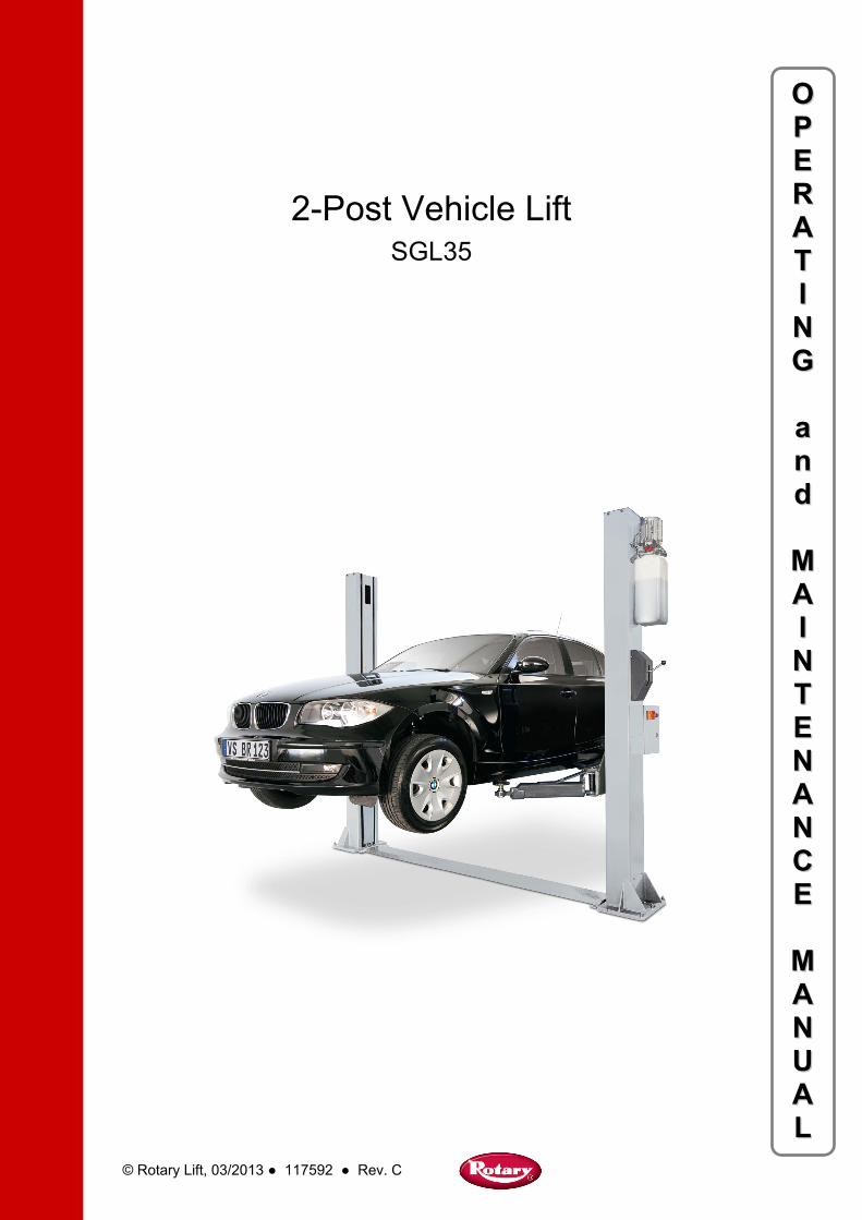
2. Operate the pump lever on the hydraulic pump (Fig. 13) (optional equipment) to raise the slider block to the locking position and to release the latch mechanism.
3. Hold down the latch mechanism lever (Fig. 7) to release the mechanical safety latches.
4. Loosen and remove the lock nut of the hydraulic solenoid valve for lowering the lift (Fig. 14).
5. Slowly and carefully loosen the knurled head screw of the hydraulic solenoid valve (Fig. 14, arrow) to slowly lower the slider block. The lowering action is stopped when the screw is tightened.
6. After lowering, tighten the screw again and replace the lock nut.
Note: If lowering stops after just a brief moment, the mechanical safety latches have engaged. Please contact the maintenance technician at your authorised dealer.
DANGER
Risk of death due to unsafe operation of the lift
Careful use by authorised and qualified operators
The area around the lift must be made safe in compliance with national regulations
Make sure that the lift moves steadily and smoothly
The load must be stable at all times
If the vehicle is not stable, the lowering process must be halted immediately
13
14
i
Pump lever
Hydraulic pump
Screw cap

6. Action in the event of a fault
18 117592 ● 03/2013
6.4 Recommissioning the lift after incorrect alignment of the slider blocks
If the slider blocks are not horizontally aligned at the same level (outside the approved control limits), halt operation of the lift and check for the cause.
An alignment error such as this may be caused by:
An obstacle which is hampering the slider blocks or the arm: Remove the object.
A mechanical safety latch is still engaged Check the status and adjust the latch control cable (Fig. 25)
The weight is very unevenly distributed: see the chapter “Emergency lowering during a power failure“
A synchronisation cable has become slack for no obvious reason: press the "Up” button, to tension the cable again (Fig. 25)
A synchronisation cable or a lifting chain is damaged: set the main switch to “0“ and lock with the key switch. Replace the damaged part.
If the malfunction cannot be repaired, please contact the customer service at your authorised dealer.
15
i
Short cable clamp
Latch
Cable clamp
Secondary column
Anchor
Long cable clamp
Mounting plate
Primary column
Latch Cable clamp

7. Maintenance
19 117592 ● 03/2013
7. Maintenance
7.1 Maintenance staff qualification
Maintenance work may only be carried out by competent persons ( chapter 1.3). Parts lists do not act as authorisation for maintenance or repairs on the lift, unless otherwise expressly stated in the operating manual. They are only designed to provide information to the maintenance technician of the authorised dealer.
Only specialists with specialist knowledge and experience of hydraulics may work on hydraulic equipment.
7.2 Safety regulations
Only OEM parts supplied by authorised dealers may be used. If these parts are not used, the manufacturer of the lift shall not assume any liability and the warranty shall become null and void. Maintenance and service work may only be carried out on equipment which is switched off and locked.
Before any maintenance or adjustments, disconnect the lift from the power supply. Also make sure that all mobile components are securely locked.
Inform everyone in the lift zone of the maintenance work.
Avoid contact with or inhaling of toxic substances such as hydraulic fluid, as well as environmental hazards. If required, wear protective clothing, e.g. protective goggles, protective gloves, etc.
After design modifications to or repair of safety-related parts, the lift must be inspected by a certified expert.
Before carrying out maintenance work, display a warning sign and secure the lift zone with a red-white chain.
Tighten fasteners after maintenance with the specified torque.
Do not disassemble or modify lift parts – only maintenance technicians from the authorised dealer may do so.
Follow the maintenance schedule, document the maintenance work ( maintenance report).
7.3 Maintenance schedule
Lifts in especially dirty environments must be cleaned and maintained more often.
Oil and grease are water pollutants. Always dispose of them in an environmentally friendly manner according to the regulations applicable in your country ( Chapter 14, Disposal).
Daily
1. After finishing work, lower the lift fully and lock to prevent unauthorised use.
2. Clean the lift and the work zone.
3. Check the condition and wear on cables and sheaves.
4. Check that the latches are not permanently bent.
Monthly
1. Check the hydraulic oil level ( chapter 7.5).
2. Check the controls for functionality and the electrical cables for damage.
3. Check the seals on hydraulic components ( chapter 7.7).
4. Carry out a function test with or without load (chapter 7.9).
5. Check the tension of the synchronisation cables.
6. Check whether screws and bolts are secure
Annually
1. Carry out a safety inspection ( chapter 12).
2. Inspect and if necessary adjust the synchronisation cables ( chapter 12).
Every 2 years
1. Change the oil (chapter 7.5).
i
i
i
i
i
i
i
i
i
i
i
i

7. Maintenance
20 117592 ● 03/2013
7.4 Cleaning
Keep the lift and the lifting zone spotlessly clean. Never use compressed air, water jets, solvents, or abrasive cleaning materials to clean the lift. If possible, avoid build up of dust when cleaning the lift. Unauthorised staff may not carry out maintenance work.
Regularly clean the lift.
Only clean the lift when it is not loaded.
Do not use abrasive cleaning materials to clean the lift parts and covers.
Always use lint-free cloth.
Do not use compressed air or high pressure cleaners for cleaning.
Always inform the maintenance staff if you notice any hazards.
To begin cleaning, make sure you first clean the connections and fittings of oil, grease, and cleaning materials.
7.5 Check the hydraulic oil level
Check the oil level.
Check the hydraulic oil level of the hydraulic unit
Lower the slider blocks to the bottom position.
Check the hydraulic oil level of the hydraulic unit. If necessary, top it up with a suitable oil (see adjacent table ). Use the filling nozzles to top it up.
Check the hydraulic oil in the tank about every 1000 operating hours (11 litres).
Make sure that there is no residue in the tank. New oil must be filtered.
7.6 Approved hydraulic oils
Important advice
Only use hydraulic oil according to DIN 51524 for hydraulic systems.
Please inform us if you want to use hydraulic oil from another manufacturer.
ATTENTION Seals could be destroyed if the wrong hydraulic oil is used.
Do not use rapeseed-based oil.
The water content in the hydraulic oil may not exceed 2 %.
Do not mix different types of oil.
Check if there is sufficient oil on the lifting chains and safety chains. If the coating of oil is too thin, apply oil with a spray nozzle. Oil and grease specifications:
Brand Hydraulic oil Chain oil Lubricant
TOTAL AZOLLA 32 CHAINELUB -
ELF OLNA DS 32 MOTO CHAINELUB
-
ESSO NUTO 7132 -
BP BARTRAN 32 -
MOLYKOTE - BR 2 (1-kg-
box)
7.7 Check the hydraulic component seals
Only inspect an unloaded lift.
1. Remove the cover plate to gain access to the hydraulic cylinders
2. Check the seals on all hydraulic components.
3. Switch on the lift.
7.8 Inspect and adjust the synchronisation cables
Move the lift up to check the tension of the synchronisation cables.
i
i
i

8. Repairs
21 117592 ● 03/2013
Hold the cables just under the slider block between your thumb and forefinger and press together with approx. 70 N of force.
Adjust using the bolts at the top.
OR:
Carry out 5 full cycles (up/down) with a vehicle so that the cables have been correctly stretched.
Remove the vehicle from the lift.
Raise the slider to the top position against the mechanical stop.
Finally, tighten the bottom nuts on the threaded cable ends, until the tension of both cables is identical.
Carry out a cycle without a load, align the arms with each other to see if they are at the same level.
If necessary, adjust the cable tension.
If the slider blocks are at the same level, the mechanical safety latches must engage at the same time.
Carry out several cycles with a load, in doing so make sure that the vehicle is centred on the longitudinal axis of the lift.
If this is not the case, then carry out re-adjustments.
Further instructions on adjusting the synchronisation cables can be found in section 12.
7.9 Carry out a function test
WARNING
Risk of injury through function failures.
If lift functions fail, shut down and lock the lift immediately.
Immediately correct the failures and ensure that the operation runs smoothly.
1. Check full functionality of the lift without load.
2. Check full functionality of the lift with load.
8. Repairs
Repair work may only be carried out on equipment that is switched off and locked by trained and authorised specialists.
Refer to the safety regulations in chapter 7.2.
All repairs must be documented ( Form “Unscheduled safety inspection“).
9. Safety inspections To guarantee the safety of the lift when in operation, it is necessary to carry out safety inspections.
Safety inspections should be carried out in the following cases:
Initial installation: Use the form “Initial safety inspection before commissioning“.
Annual: Use the form “Annual safety inspection“.
Unscheduled safety inspection: After any design modification to lift parts. Use the form “Unscheduled safety inspection“.
Safety inspections may only be carried out by competent persons or certified experts.
10. Transport, storage
10.1 Storage
Lift components must always be kept in a dry place (no corrosion protection).
Recommended storage conditions Ambient temperature: -5 ... +50
Relative humidity, 30 % ... 95 % without condensation, at 20 °C
The manufacturer provides no warranty for corrosion damage caused by incorrect storage.
10.2 Transport
DANGER
Danger of crushing and shearing of limbs when unloading. Caused by collapsing or slipping loads.
i

10. Transport, storage
22 117592 ● 03/2013
Do not loiter close to or under suspended loads.
Always unload the packing unit with a forklift truck or a pallet jack with sufficient load capacity and transport it to the storage point.
Always use hoisting equipment (straps, chains, etc.) approved for the total weight.
Attach them so that the load cannot slip (check the centre of gravity of the load).
Always fasten individual components to load-bearing parts. Only lift vertically, steadily, and without jolting.
Carry out a visual inspection before unloading.
Secure loose parts.
When raising or lowering, always monitor the danger zones.
Always transport hydraulic components without oil.
Protect controls and hydraulic units against adverse weather conditions and avoid sudden fluctuations in temperature
10.3 Unpacking
Unpack the lift with the forwarder still present.
After removing the packaging, carry out a visual inspection to ensure that the various components of the lift are OK (arms, columns, control units, etc.)
If damage is found, please note this on the shipping documents. Do not commission the lift and contact your authorised dealer immediately.
Packaging materials (polythene, plastic sheets, polystyrene, boxes, pins, screws, wood, etc.) must be kept out of reach of children, since they pose a potential hazard. Always dispose of the environmentally unfriendly and non-biodegradable materials at the appropriate collection points. Please comply with any local regulations and standards.

11. Installation
23 117592 ● 03/2013
11. Installation
11.1 Installation guidelines
CAUTION
Refer to the health & safety requirements when choosing an installation site
Shut down and secure the lift immediately if function failures occur.
Immediately correct the failures and ensure that the lift operates smoothly.
Allow sufficient clearance around the lift. More information can be found in this chapter.
The lift is set up by trained fitters from the manufacturer or the authorised dealer.
The customer service technician at your authorised dealer must be informed of the location of the supply lines (power, compressed air, water, etc.) in the floor, so that they are not damaged if any holes need to be drilled to anchor the lift.
The operator must be in a position to monitor the lift and its surrounding area from the control unit.
The presence of unauthorised persons, animals, and objects which may pose a potential hazard is prohibited in the lift zone. The installation location with a reliable concrete foundation must bear the loads during operation (Fig.16). The quality of the concrete (pressure resistance) must be at least 25 N/mm². The location must be straight and horizontal across the whole installation area (+/- 0.5 cm). A suitable floor covering is acceptable. The strength of the concrete slab at the installation location must guarantee that the anchor bolts sit perfectly and must be the correct thickness of at least 15 cm for the SGL35H lift or 20 cm for the SGL35N lift (Fig. 17). If the lifts are installed on an upper floor, please seek the advice of an architect. The clearance on both sides of the column must be at least 800 mm (Fig. 7).
Standard type lifts must not be installed in zones at risk from explosion.
Ensure an adequate foundation before installation. Alternatively, this can also be created according to the foundation plan guidelines.
M = Tilt movement specified in kNm on the column base plate F = Force specified in kN
16
Lift Mx My F
SGL35 13.2 9.2 21
17
If the installation site is affected by frost or wintry weather, the foundations must be to the frost depth.
Refer to the technical data in chapter 3.3. Document correct installation in the inspection logbook. To do so, use the form “Initial safety inspection before commissioning“.
We recommend above floor supply lines at the height of the hydraulic unit.
If the supply lines are laid in the floor, use cable ducts to protect the power cable.
The power supply is 230 V or 400 V 3 Ph PE 2.2 kW, cable 4x2.5 mm² H07RNF: This cable type must be used at a cable length of below 10 m and for a 400 V power supply. If this is not the case, please contact your local electrician.
The primary column can be installed to the left or the right. Standard recommended installation is on the right hand side in the drive direction of the vehicle.

11. Installation
24 117592 ● 03/2013
11.2 Mechanical installation
a) Preparation before installing the columns Identify the columns with the help of the latches
on the mechanical safety system: The primary column is fitted with one cable clamp for the latch control cable (Fig. 19).
19
Before installing the preassembled columns, mark out the outer distance between columns of 3320 mm on the floor to help you. Then align the columns with this (Fig. 18).
Place the two columns on the floor at the installation site.
Now run in the synchronisation cables and the latch cable before aligning the columns according to the diagram in Fig. 22.
b) Assembling the columns Use a piece of wood (from the packaging) to
support the slider block 10 cm above the base plate. Use suitable lifting gear and handling equipment to set up the two columns in their upright position.
Make sure that the cylinders stand properly in the column.
c) Floor anchoring
CAUTION
Select the installation location
Do not assemble the lift on asphalt or similar unstable surfaces. The columns are only held in the floor by anchors.
The concrete should have a compression strength of at least 20 N/mm² and a minimum thickness of 200 mm to achieve a minimum anchoring depth of 105 mm.
18

11. Installation
25 117592 ● 03/2013
Set up the columns vertically or slightly tilted outwards with the help of a plumb line. If the floor is not level, use the supplied shims under the columns to align them.
The mounting holes with a diameter of 20 mm are drilled with the help of a hammer drill. Use the drill template in the column base plates as a guide (Fig. 21). Please also refer to the adjacent table and work instruction in Fig. 22.
21
Drill diameter 20 mm
Recommended concrete thickness
200 mm
Drilling depth A 140 mm
Anchoring depth C 105 mm
Anchor bolt Quantity min. 5 per column
Type M20 x 200/60
Tightening torque 200 Nm
Minimum distance to edge of foundation slab
100 mm
If the required tightening torque cannot be
reached, either the hole is too large and the thickness or the compression strength is too low.
20
Short cable clamp
Cable clampLatch
Secondary column
Anchor
Long cable clamp
Mounting plate
Primary column
Cable clamp Latch

11. Installation
26 117592 ● 03/2013
11.3 Hydraulic installation
The hydraulic lines are fully pre-assembled as in Fig. 24.
After the hydraulic lines have been fitted, fill the supplied oil into the hydraulic unit tank (11 litres).
11.4 Electrical connection
CAUTION
Comply with local regulations
The electrical connection and the protective measures must be carried out by an authorised specialist according to the regulations which apply in your country.
Refer to the operating table of the motor
Install a separate circuit breaker between energy supply and power supply unit
The lift must be fitted with a main switch by the customer.
The local regulations take precedence when selecting protective measures.
a) Assemble the control unit
Assemble the control box (Pos. 6) according to page 40 with the M4 x 8 Philips head cylinder screws (Pos. 16).
b) Connecting the hydraulic unit to the power supply
Connect the two cables marked 0 and 21 at the connection of the solenoid valve.
Fit the lowering solenoid valve with its screw.
Connect the two cables marked 23 and 25 at the right hand connections of the electric motor.
The power supply configuration depends on the following parameters:
The power consumption of the hydraulic unit and the connection to the power supply must be such that voltage drops at full load are less than 4 percent (10 percent during the start-up phase) according to the nominal voltage on the name plate.
The user must:
Connect the main switch of the control unit to a junction box (according to local standards) and to a cable protected against overcurrent and with an earth leakage circuit breaker;
Ground the lift circuit. Before connecting the controls to the power supply, proceed as follows:
Ensure that the installed fuses and main fuses are fit for the purpose (16-A fuses). The lift works as standard with 400 V and connections are available for this voltage.
If the power supply is 230 V, proceed as follows:
22 I II III IV
Drill holes with a 20 mm masonry drill with a
carbide bit
Clean out the hole Tighten the nut until it engages, Turn the anchor in the hole until the nut and the lock washer touch the base plate
Tighten the nut to 200 Nm with an adjustable wrench

11. Installation
27 117592 ● 03/2013
Disconnect the cable from the 400 V terminal on the transformer and connect it to the 230 V terminal.
Remove the cover of the motor terminal box.
Loosen the M5 lock nuts on the terminal strip and change its position (Fig. 23)
Tighten the M5 lock nuts again and replace the terminal box cover.
To prevent any danger arising from the power supply, tighten the control unit cover before connecting the control unit to the power supply. To prevent use of the lift by an unauthorised member of the staff, lock the main switch of the control unit. Connect the control unit to the power supply.
23
CAUTION
Grounding
The ground connector is essential to proper operation of the lift.
NEVER ground to gas, water, telephone, or other lines which are not expressly intended for grounding.
11.5 Final assembly of the mechanical unit
a) Installing the synchronisation cables
The synchronisation cables and the lock cable are fully installed with the columns in an upright position.
To do so, the slider blocks must be set up at the same height in the centre of the vertical travel and engage the rack teeth.
Now go back to Figure. Fehler! Verweisquelle konnte nicht gefunden werden. and proceed as follows:
Check that the cable is properly routed. Fit the short cable clamp of the metal cable (Pos. 95) to the slider block with a washer (Pos. 96) and a self-locking nut (Pos. 97).
Repeat this procedure on the opposite column.
Take the long cable clamp and fit it with a washer and a self-locking nut.
Do the same with the second cable.
Carry out a final adjustment as per section 12 to check that the two cables are equally tensioned.
b) Assembling the latch mechanism
Assemble the latch mechanisms according to the drawings on page 42.
i
i
i

11. Installation
28 117592 ● 03/2013
c) Assembling the latch cable
To make this step easier, raise the slider block to the top position.
Feed the end of the cable into the latch control cable clamp on the primary column and tighten the clamp (see Fig. Fehler! Verweisquelle konnte nicht gefunden werden.).
Feed the other end of the cable upwards through the sheave to the latch cable clamp of the secondary column.
The control cable is routed in the column.
Screw the mechanical safety lever onto the primary column latch.
Adjust the tension of the cable with the clamp so that both latches disengage from their rack at the same time when you pull the latch mechanism lever.
d) Assembling the arm
24
i
i
11. Installation
29 117592 ● 03/2013
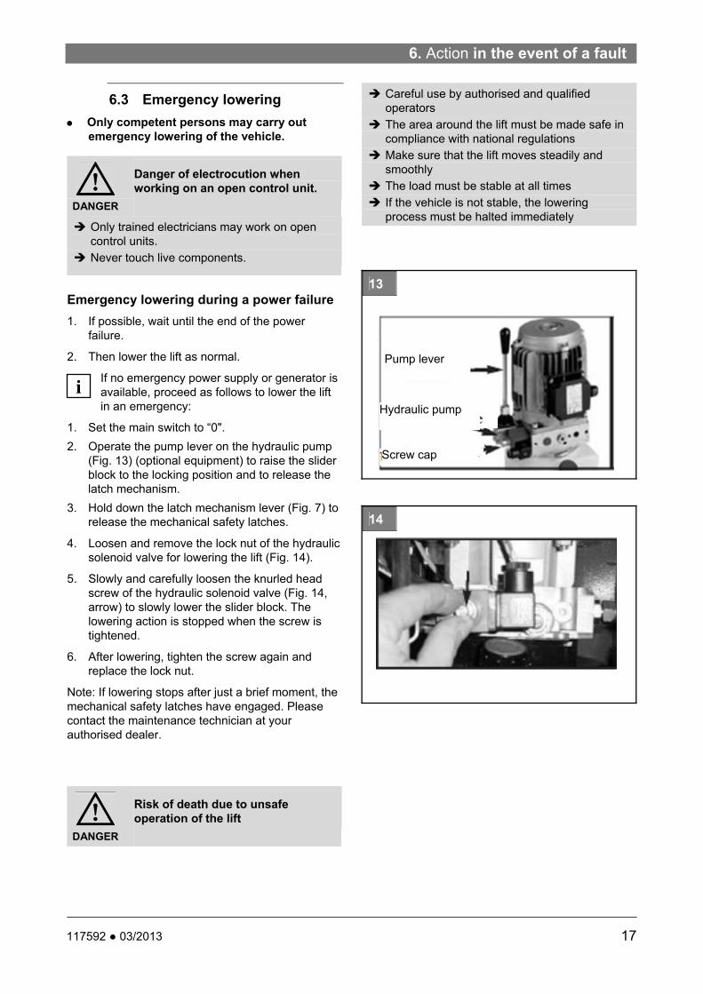
CAUTION
When assembling the bolt
Pinch point
Keep hands above the nut
Before installing the arms, bring the slider block to a suitable height.
Lubricate the sweep arm pins and holes with lithium grease. Insert the arm into the bracket.
After attaching the arms and the bolts, attach the guide mechanism as follows:
25
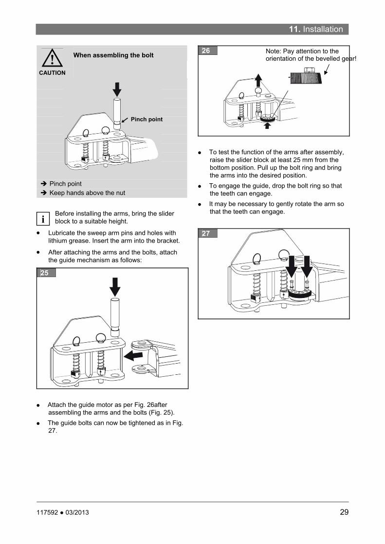
Attach the guide motor as per Fig. 26after assembling the arms and the bolts (Fig. 25).
The guide bolts can now be tightened as in Fig. 27.
26
To test the function of the arms after assembly, raise the slider block at least 25 mm from the bottom position. Pull up the bolt ring and bring the arms into the desired position.
To engage the guide, drop the bolt ring so that the teeth can engage.
It may be necessary to gently rotate the arm so that the teeth can engage.
27
i
Pinch point
Note: Pay attention to the orientation of the bevelled gear!

12. Commissioning
30 117592 ● 03/2013
12. Commissioning
Carry out a “safety inspection“ before commissioning.
If a competent person (factory-trained fitter) installs the lift, this person also carries out the safety inspection.
If the operator installs the lift, a competent person must be assigned to carry out the safety inspection.
The competent person completes the forms “Installation Report“ and “Initial safety inspection before commissioning“ and verifies that the lift is fully functional. The lift is now approved for use.
The installation report must be sent to the manufacturer after commissioning.
The installation and commissioning of electrical and hydraulic equipment, safety system and accessories are described in the following sections. Follow the correct sequence to guarantee that the lift can be operated correctly, in order that the safety of people is not at risk.
CAUTION
Follow the instructions
Any damage caused through non-compliance with the instructions below cannot be attributed to the manufacturer; in such a case, the manufacturer shall assume no liability. The warranty shall also be deemed null and void.
a) Electrical circuit
If the hydraulic unit is connected to the power supply and the main switch is set to “1“ the control unit is activated.
Press the "Up" button for several seconds and check that the motor is turning properly.
If there is no build up of pressure and the slider block does not move, then alter the direction of rotation of the motor by inverting the phases of the power cable.
Carry out another check.
Check all functions of the controls and ensure that they react in accordance to the symbols.
b) Hydraulic circuit Proceed as follows to commission the hydraulic circuit: Set the main switch to “1“ to supply power to the
control unit.
Raise and lower several times without load up to the end limits.
Ensure that the hydraulic system fittings are properly sealed.
Check the hydraulic oil level in the tank when the slider block is in the bottom position.
Check that the hydraulic lines are correctly positioned and that they do not chafe against stationary parts.
c) Adjust the calibration pressure of the hydraulic circuit Install a manometer (Fig. 29) on the fitting
provided for the pressure gauge.
28
Press the "Up" button to raise the slider block to the mechanical stop at full rise.
Keep the button pressed for a further few seconds after the slider block has touched the stop at full rise and read the pressure off the manometer.
If this pressure does not correspond to the calibration pressure of the hydraulic circuit as specified under “TECHNICAL DATA“ use the adjustment screw (Fig. 28, arrow) on the pressure release valve behind the lock nut to adjust it.
Fit a plastic cap (orange) to the lock nut to lock the pressure release valve.
29
d) Broken chain control (lifting chains)
Each slider block is fitted with a chain:
i
i
i

12. Commissioning
31 117592 ● 03/2013
Each of the chains is fitted with a micro switch (Fig. 30), which monitors the chain tension. If the chain breaks or is excessively slack the micro switch is actuated and all movement is halted.
30
Proceed as follows to check the broken chain control of the lifting chain:
Manually raise the slider block to full rise.
Make sure that the slider block triggers the micro switch and that all lift controls are inactive. If this is not the case, adjust the micro switch bracket accordingly so that it is triggered.
Do the same for the broken chain control of the opposite column.
e) Arm restraint
Each pinion must engage in the corresponding ring gear, as soon as the slider block is raised from the floor. If one of the pinions does not engage, the bolt remains in its top position.
Adjust the arm restraint accordingly.
Slider block in the bottom position: Pull on the end of each arm to ensure that the stop bolt prevents the arm from moving further outwards. Otherwise restore the arm to its original position and tighten the stop bolt.
f) Levelling the height of the slider blocks
Pick up a medium sized vehicle on the lift
Raise the vehicle up to the first safety latch
Manually release the latch on the control side
Set the lift down on the other latch
Effect:
The slider block on the opposite side moves into the safety latch, the slider block on the control side keeps moving until the synchronisation cable is
pulled tight and brings the slider block on the control side to a halt (cable is loaded).
Raise the vehicle again up to the first latch.
Repeat 2-4 times with the safety latch on the opposite side.
Raise the vehicle and check the synchronisation.
If necessary, re-tension the synchronsation cable

13. Disassembly
32 117592 ● 03/2013
13. Disassembly Disassembly work may only be carried out by
authorised specialist staff.
Electrical work may only be carried out by qualified electricians.
Work on the hydraulic or pneumatic equipment may only be carried out by trained persons with specialist knowledge of hydraulics/pneumatics.
Hydraulic oil, lubricants, cleaning materials, and replaced parts must be disposed of in accordance with environmental regulations.
Follow the environmental procedures for disposal ( chapter14.2). Prevent environmental hazards.
System components must be disposed of in compliance with the directives which apply to your country.
14. Disposal
14.1 Packaging
Do not dispose of with general waste! The packaging consists partly of recyclable materials and partly of substances which do not belong in general waste.
Dispose of packaging materials in accordance with local regulations.
14.2 Environmental procedures for disposal
Prevent environmental hazards.
Avoid contact with or inhalation of toxic substances such as hydraulic fluid.
Oils and lubricants are water pollutants under the terms of the Water Management Act WGH. Always dispose of these in an environmentally friendly manner in accordance with the regulations which apply in your country.
Mineral-based hydraulic oil is hazardous to water and combustible. Refer to the relevant safety data sheet when disposing of it.
To drain the oil, use a suitable oil drain pan and an oil-binding agent.
Ensure that no hydraulic oil, lubricants, or cleaning materials pollute the ground or leak into the drainage system.
Identify all materials for recycling.
Special waste must be separated and subdivided into equal lots and then disposed of in accordance with national legislation and standards.
14.3 Metals / Electronic waste
Dispose of the various materials, scrap metal, and electrical waste via the appropriate disposal centres. Comply with the relevant national legislation and standards, in particular the EU Waste Electrical and Electronic Waste Directive.

Annex Post Lift SGL35
33 117592 ● 03/2013
ANNEX
Notes on conducting a visual inspection and a function test
Diagrams, spare parts lists
Electrical circuit diagram see control box
Hydraulic diagram
Spare parts lists
Hydraulic power unit

Annex Post Lift SGL35
34 117592 ● 03/2013
Notes on conducting the visual inspection and function tests
Check the following in particular in the course of a regular inspection:
1. Information on the lift Inspection criteria Nameplate Labelling Brief operating instructions
Securely fastened Legibility Complete
2. Full operating manual Condition Legibility
3. Warning signs Condition Visibility
4. Protection against unauthorised use
Condition Function Accessibility Safety key
5. Manual controls Raising, lowering Supports
Condition Function Accessibility Clear assignment Permanent indication of direction Protection against accidental actuation
6. Emergency off switch / Emergency lowering valve
Condition Function Accessibility
7. Signalling devices
Condition Function Visibility Reliability
8. Parts used for stable installation Supports Base plate Floor anchoring
Condition Function Wear Deformation Corrosion Cracking
9. Bearing structure Cracking Deformation Corrosion Accessibility of guides, sheaves, joints/hinges, telescopic parts, Wear and tear of guides, sheaves, bearings, joints/hinges Detachable connections must be strong and secure Effectiveness of locks

Annex Post Lift SGL35
35 117592 ● 03/2013
10. Pick-up equipment Anti-slip protection Roll stop Clamping equipment Arm restraints
Condition Function
11. Steel cables / steel links Wear Corrosion Torn strands Torn strand nests Crushing Outer layer fraying Bird caging
12. Sheaves Cracking Signs of wear Burr formation in the cable grooves Correct alignment
Cable winder Clamps Protection at cable attack points Protection against cable jumping out of sheaves
Condition Function
13. Steel sprocket chains / chain links
Accessibility Wear Flaws Secure bolts e.g. through rivet head, ring
Chain sprocket
Condition Function
Clamps Protection at chain attack point
Condition Function
14. Hydraulics Leaks Seal test Bleeding
Oil tank Condition of oil Check level
Wiring Wire connections
Strength Damage Deformation Corrosion Water tightness
Hoses Hose connections
Strength Damage Ageing Brittleness Porosity Seals
Cylinders Strength Cracks Pipe and hose connections Seals and sleeves
Pistons Surface of piston rod Scoring

Annex Post Lift SGL35
36 117592 ● 03/2013
Dirt Filter Surface condition
Pressure release valve Surface condition Seals undamaged
Lowering valve Surface condition, seals 15. Electrical equipment Wires Damage, strength, strain relief on outer wires Grounding conductor Damage, strength
16.Safety latches Effectiveness, strength, condition, damage
17. Special safety mechanisms Emergency stop, Broken chain switch, Control locks, Emergency stop bars, restart protection, Safety catch mechanism,
Effectiveness, strength, condition deformation, accessibility of switches Dirt, condition of springs,

Diagrams, spare parts lists
37 117592 ● 03/2013
Electrical Circuit Diagram
Label Description Label Description
F1 16-A fuse S5 Slack cable switch / Secondary column
F2 5-A fuse S6 Broken chain switch / primary column
F3 Thermal protection integrated in motor S7 Slack cable switch / primary column
S1 Main switch S8 Mechanical SAFETY lever switch
S2 UP button T1 Transformer 230 V / 400 V - 24 V
S3 DOWN button KM1 Power relay 24 VAC
S4 Broken chain switch / secondary column
HV1 Hydraulic lowering solenoid valve 24 VAC
M1 3-Phasen-Motor 230 V / 400 V
mai
n ci
rcui
t
Co
ntr
ol c
irc
uit

Diagrams, spare parts lists
38 117592 ● 03/2013
Hydraulic diagram
CY
INN
DE
R
VE
LO
CIT
Y F
US
E
LO
WE
RIN
G V
AL
VE
Han
d p
um
p
(op
tio
n)
1395
re
v/m
in.
2.2k
W
5.0
cc/
rev
205
BA
R
7 I/m
in

Diagrams, spare parts lists
39 117592 ● 03/2013
Spare parts list
Item Drawing no. Name Qty
1 SGL35-1000 Welded primary column 1
2 SGL35-1100 Welded secondary column 1
3 SGL35-6004 Cover plate 2
4 SGL35-1020 C-base plate 2
5 SGL35-3000 Welded base plate 1
6 SPOA-B100 Control box 1
7 HTF9-3003 Mounting bracket cover plate 4
8 K35-1117 Hook 4
9 B30-4 M4 nut 4
10 B12-8×25 Hex bolt M8x25 4
11 B41-8 Washer Ø8 24
12 B33-8 Nylon lock nut 4
13 30400-1999 Vibration washer 4
14 Concrete anchoring bolt 3/8"x2.75"
4
15 N/A Concrete anchoring bolt 10
16 B23-4×8 Philips head cylinder screw M4x8 4
17 B23-4×6 Philips head cylinder screw M4x6 8
18 B23-6×8 Philips head cylinder screw M6x8 28
19 SGL35-2000 Top welded cover plate 2
20 52005 Top sheave 4.75" 2
21 30400-1005C Washer 6
22 B60-25 Snap ring Ø25 10
23 52004A Bearing bushing 2
24 30400-1005B Lower sheave 4.75" 4
25 30400-1005B-01
Bearing bushing 4
26 B30-10 M8 nut 8
27 B20-8×30 Cylinder screw M8x30 8
28 B40-8 Lock washer Ø8 8
29 SGL35-1008 Column cover plate 2
30 NK35-7004 Spacer ring 2
31 NK35-7001 Welded chain anchor 2
32 NK35-7007 Chain spring 2
33 B30-16 M16 nut 4
34 SGL35-1009 Switch mounting plate 2
35 B30-3 M3 nut 4
36 B23-3×20 Cylinder screw M3x20 4
37 V15F06C Switch 2
38 SGL35-5000 Welded slider block 2
39 HPRO-2008 Slider block cover plate 2
40 30400-5024 Bearing blocks 16
41 FJ7985-1 Ring 4
42 N119-3 Snap ring 1" 4
43 G3T-3006 Actuator pin 4
44 G3T-3005 Spring 4
45 N2121 Locking latch 4
46 14427 Locking pin Ø0,25x1.5" 6
47 91773-2 Bearing bushing 2
48 91773 Chain sheave 2
49 30400-9012-01 Chain sheaves axle 2
50 NYG01-9100 Hydraulic cylinder 2
51 BL644*107P Chain 2
52 30400-5023 Chain bolt 4
53 B52-2×20 Locking pin Ø2x20 8
54 B23-6×16 Cylinder screw M6x16 4
Item Drawing no. Name Qty
55 SGL35-6003 Cable duct 2
56 SGL35-6002 Synchronisation cable 1
57 N619 Cable mounting 4
58 G3T-5001 Arm bolt 4
59 40155 Hex bolt 3/8"-16x5/8" 8
60 40843 Lock washer3/8" 8
61 N2122 Sprocket 4
62 SPL35-4300 Welded outer section 4
63 SPL35-4200 Welded middle section 4
64 SPL35-4100 Welded inner section 4
65 40818 Lock washer 3/8" 12
66 40373 Hex bolt 3/8"x1.5" 12
67 G3T-5401 Rubber adapter 4
68 G3T-5402 Welded arm adapter 4
69 G3T-5403 Connecting part A 4
70 G3T-5404 Connecting part B 4
71 G3T-5405 Snap ring 4
72 G3T-5406 Snap ring 4
73 FJ6191-9 Snap ring Ø42.5 (in) x 2.65 4
74 41655 Bolt M5x0.8x10 16
75 PV-1001 Locking latch cover primary column
1
76 PV-1002 Locking latch cover secondary column
1
77 B84-35 Locking latch ball bearing 1
78 PV-1007 Latch lever 1
79 B60-20 Snap ring Ø20 4
80 B41-20 Washer Ø20 4
81 PV-1006 Latch axle 2
82 PV-1040 Locking latch spring 2
83 PV-1009 Locking latch spring 1
84 PV-1015 Spacer ring 2
85 PV-1005 Latch block 2
86 PV-1003 Control plate 1
87 PV-1008 Hex bolt 2
88 B20-6×16 Cylinder screw M6x16 2
89 B30-10 M10 nut 1
90 PV-1013 Latch cable sheave 3
91 B60-10 Snap ring Ø10 3
92 PV-1009DC Locking latch spring 1
93 PV-1004 Control plate 1
94 B21-6×16 Cylinder screw M6x16 2
95 SGL35-6001 Steel cable 2
96 B41-12 Washer Ø16 4
97 B33-12 Stop nut M12 4
98 10#-24 Latch cable bracket 1
99 CP08100 Hydraulic power unit 1
100 SW-002 Right angled fitting 1
101 1WB-13JC Short hydraulic hose 1
102 H4D-Y003 Fitting 1
103 SGL35-9801-1 Hydraulic hose primary column 1
104 30400-9052YZ Fitting 1
105 SGL35-9200 Restrictor valve 1
106 30400-9054(B)YZ
Fitting 4
107 SGL35-9802-1 Fitting 2
108 SGL35-9801-2 Hydraulic hose - floor 1

Diagrams, spare parts lists
40 117592 ● 03/2013
Figure 1

Figure 2

Diagrams, spare parts lists
42 117592 ● 03/2013
Figure 3
Figure 4

Figure 5
Figure 7
Figure 6
Diagrams, spare parts lists
44 117592 ● 03/2013
Figure 8

Figure 9

Diagrams, spare parts lists
46 117592 ● 03/2013
Hydraulic power unit
Box with core hitches
V3.892.71.OST (CHECK VALVE)
V3.889.26.A03 (RELIEF VALVE)
PIPE RILSAN

Pos: Qty. Code Description
1 1 KE971PL05Z M04.Z central manifold KE 2000 (80‐250 bar)
2 1 KE970TR008 TR08 Coupling
3 1 V389669E20 VE1‐NC‐EM electric valve cav.V096004
4 1 R3897TA226 TC4 Plug for cavity‐(only thread)
5 1 V388540000 PMC12 Hand pump (1.5 cc)
6 1 K250113000 Lever M10 L=190 mm
7 1 CV10114302 18GH pump 5.0cc + screw M8x85
8 1 K3976SE449 S423 Plastic Tank 12Lt.
9 1 K234062000 Suction pipe 3/8" L=385
10 1 K225566000 Suction filter 3/8" female 15l/min (90 micron)
11 1 K234722000 Return pipe M12x1 l=400
12 1 C014120000 Adaptor 3/8" for pipes Ø6/4
13 1 C1622S1380 948 Electric motor three phase 2.2kW 230‐400V 50Hz
14 1 V38951900G STF14P Compensated flow control valve 7l/min
15 1 C166401OH2 S2‐CE+C Coil 24Vac 50Hz 18W with connector
16 1 CR12009000 Plug DIN 908 1/4"BSPP + copper ring
17 1 F331514000 G80 mounting bracket
18 1 K2501VT014 Assembly kit for plastic tank
19 1 R3897PB001 Sealing plastic cap for relief valve
20 1 C165747000 Oil filling plug 1/2"BSPP
21 1 C013620000 Adaptor 1/4" ‐ JIC 1/2"‐UNF

Diagrams, spare parts lists
48 117592 ● 03/2013

halte
n
BlitzRotary GmbH Fon +49.771.9233.0 USA: +1.812.273.1622 (Headquarter) Hüfinger Straße 55 Fax +49.771.9233.99 Canada: +1.905.812.9920 D-78199 Bräunlingen [email protected] United Kingdom: +44.178.747.7711 www.blitzrotary.com AustralAsia: +60.3.7660.0285