TWO POST LIFT INSTALLATION AND OWNERS MANUAL Capacity ... Lift I... · 3 Section 1 Owner’s Manual...
36
TWO POST LIFT INSTALLATION AND OWNERS MANUAL Capacity 10,000 lbs. © August 2009 All rights reserved. CO7378.8 IN60005 Rev. B 8/25/2009
Transcript of TWO POST LIFT INSTALLATION AND OWNERS MANUAL Capacity ... Lift I... · 3 Section 1 Owner’s Manual...
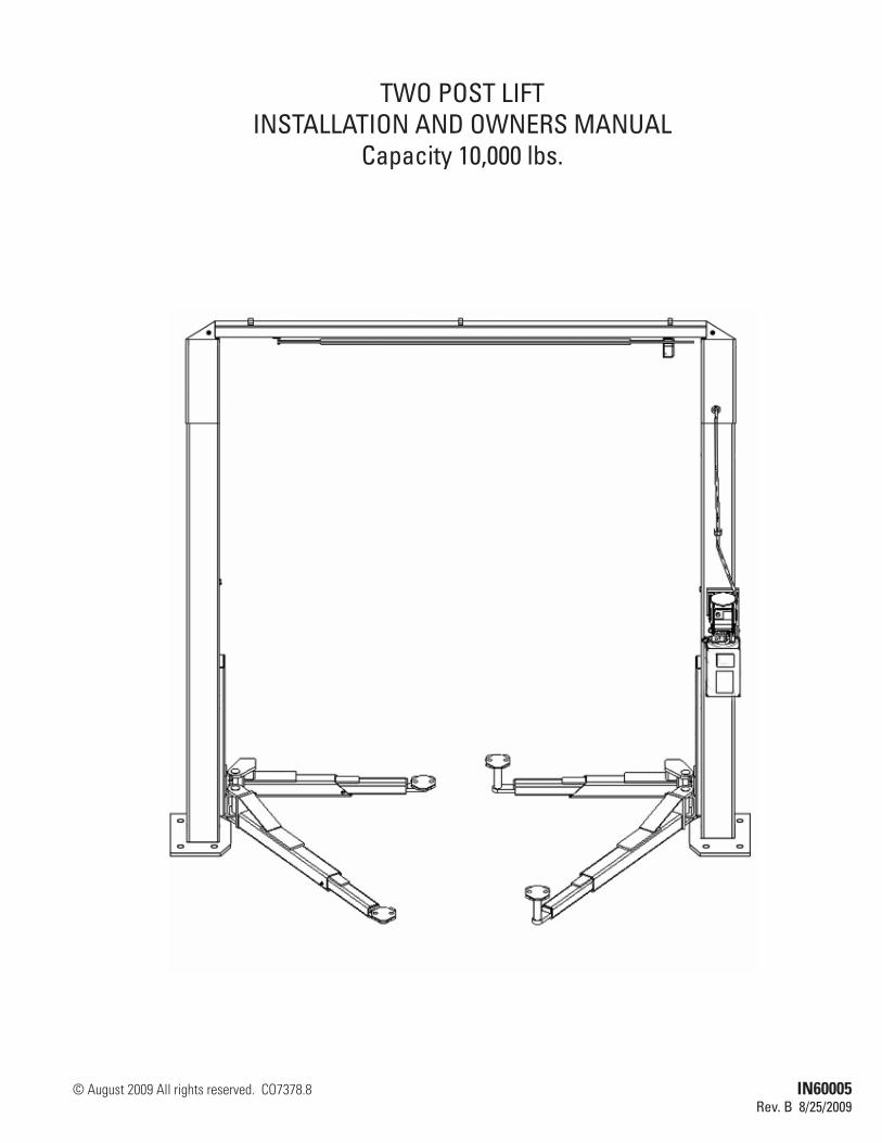
TWO POST LIFTINSTALLATION AND OWNERS MANUAL
Capacity 10,000 lbs.
© August 2009 All rights reserved. CO7378.8 IN60005Rev. B 8/25/2009
2
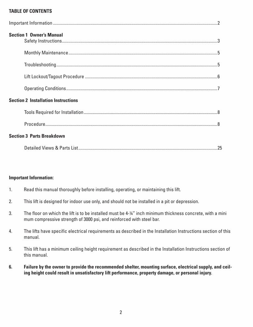
TABLE OF CONTENTS
Important Information .....................................................................................................................................................2 Section 1 Owner’s Manual Safety Instructions .............................................................................................................................................3 Monthly Maintenance .......................................................................................................................................5 Troubleshooting ..................................................................................................................................................5 Lift Lockout/Tagout Procedure ........................................................................................................................6 Operating Conditions .........................................................................................................................................7
Section 2 Installation Instructions Tools Required for Installation .........................................................................................................................8
Procedure ............................................................................................................................................................8
Section 3 Parts Breakdown Detailed Views & Parts List ..............................................................................................................................25
Important Information:
1. Read this manual thoroughly before installing, operating, or maintaining this lift.
2. This lift is designed for indoor use only, and should not be installed in a pit or depression.
3. The floor on which the lift is to be installed must be 4-¼” inch minimum thickness concrete, with a mini mum compressive strength of 3000 psi, and reinforced with steel bar. 4. The lifts have specific electrical requirements as described in the Installation Instructions section of this manual.
5. This lift has a minimum ceiling height requirement as described in the Installation Instructions section of this manual.
6. Failure by the owner to provide the recommended shelter, mounting surface, electrical supply, and ceil- ing height could result in unsatisfactory lift performance, property damage, or personal injury.

3
Section 1 Owner’s Manual
Safety Instructions:
1. Do not raise a vehicle on the lift until the installation is completed as described in this manual.
2. Anyone who will be in the vicinity of the lift when it is in use should read and refer to the following publi- cations supplied with this lift: • “INSTALLATIONANDOWNERSMANUAL” • “LIFTINGITRIGHT”,ALISM07-1. • “AUTOMOTIVELIFTSAFETYTIPS”,ALI-ST-05. • “VEHICLELIFTINGPOINTSFORFRAMEENGAGINGLIFTS”,ALI/LP-GUIDE. • “SAFETYREQUIREMENTSFOROPERATION,INSPECTION,ANDMAINTENANCE”,ANSI/ ALI ALOIM-2008.
3. Technicians should be trained to use and care for the lift by familiarizing themselves with the publica- tions listed above. The lift should never be operated by an untrained person.
4. Always position the arms and adapters properly out of the way before pulling the vehicle into or out of the bay. Failure to do so could damage the vehicle and/or the lift.
5. Do not overload the lift. The capacity of the lift is shown on the cover of this document and on the lift’s serial number tag.
6. Positioning the vehicle is very important. Only trained technicians should position the vehicle on the lift. Never allow anyone to stand in the path of the vehicle as it is being positioned.
7. Position the arms to the vehicle manufacturer’s recommended pickup points. Raise the lift until contact is made with the vehicle. Make sure that the arms have properly engaged the vehicle before raising the lift to a working height.
8. Keep everyone clear of the lift when the lift is moving, the locking mechanism is disengaged, or the ve hicle is in danger of falling.
9. Unauthorized personnel should never be in the shop area when the lift is in use.
10. Inspect the lift daily. The lift should never be operated if it has damaged components or is malfunction- ing. Only qualified technicians should service the lift. Replace damaged components with manu- facturer’s parts or equivalent.
11. Keep the area around the lift clear of obstacles.
12. Never override the self-returning lift controls.
13. Use safety stands when removing or installing heavy vehicle components.
14. Avoid excessive rocking of the vehicle when it is on the lift.

4
15. To reduce the risk of personal injury, keep hair, loose clothing, fingers, and all body parts away from mov- ing parts.16. To reduce the risk of electric shock, do not use the lift when wet. Do not expose the lift to rain.
17. To reduce the risk of fire, do not operate equipment in the vicinity of open containers of flammable liquids (gasoline).
18. Use the lift only as described in this manual. use only manufacturer’s recommended attachments.
19. Unusual vehicles, such as limousines, RV’s, and long wheelbase vehicles, may not be suitable for lifting on this equipment. If necessary, consult with the manufacturer or the manufacturer’s representative.
20. The troubleshooting and maintenance procedures described in this manual can be done by the lift’s owner/employer. Any other procedure should only be performed by trained lift service personnel. These restricted procedures include, but are not limited to, the following: cylinder replacement, carriage and safety latch replacement, leg replacement, overhead structure replacement.
21. Anyone who will be in the vicinity of the lift when it is in use should familiarize themselves with following Caution, Warning, and Safety related decals supplied with this lift and replace them if the are illegible or missing:

5
Monthly Maintenance:
1. Lubricate the four inside corners of the legs with heavy duty bearing grease.
2. With lift lowered, check the hydraulic fluid level. If necessary, add oil as described in the Installation Instruction section of this manual.
3. Check carriage latch synchronization: Latches should click at the same time. If necessary adjust equal- ization cables as described in the Installation Instruction section of this manual.
4. Check tightness of all bolts.
5. Check anchor bolt tightness. If the anchor bolts are loose, they should be re-torqued to 90ft/lbs. • Checkthenutsfortightnesseveryweekforthefirstmonth,andeverymonthafterwards.
6. Replace worn or broken parts with lift manufacturer’s parts or their equivalent.
Troubleshooting:
7. The power unit does not run: • Checkelectricalsupplybreakerorfuse. • Checkforactivationofthetravellimitswitchbyatallvehicle. • Checkmicro-switchandconnectionsinmotorcontrolbox. • Checkvoltagetothemotor. • Checkmicro-switchandconnectionsintheoverheadswitchbox.
8. The power unit runs but does not raise the lift: • Checktheoillevel. • Checkthattheloweringvalveisnotstuckopen. • Checktheconnectionsandcomponentsonthesuctionsideofthepump.
9. The power unit raises the lift empty but will not lift a vehicle. • Makesurethevehicleisnotabovetheratedcapacityofthelift. • Makesurethevehicleispositionedproperly. • Cleantheloweringvalvebyrunningthepowerunitfor30secondswhileholdingthelowering valve open. • Checkthemotorvoltage.
10. Lift drifts down. • Checkforexternalleaks. • Cleantheloweringvalvebyrunningthepowerunitfor30secondswhileholdingthelowering valve open. Repeat this procedure three times. • Cleanthecheckvalveseat.
11. Slow Lifting and/or oil foaming up. • CheckthatoilusedmeetsthespecificationintheInstallationInstructionsectionofthismanual. • Tightenallsuctionlinefittings.
6
12. Anchors continually work loose • Ifholesweredrilledtoolarge,relocatetheliftpertheInstallationInstructionsectionofthis manual. • Floorisnotsufficienttoprovidethenecessaryresistance.Removeanareaofconcreteand repour as described in the Installation Instruction section of this manual.
13. Lift does not raise and lower smoothly. • Repositionvehicleforamoreevenweightdistribution. • Checkthefourinsidecornersofthetwolegsforroughness.Anyrustorburrsmustberemoved with 120 grit emery cloth. • Lubricatethelegcornerswithheavydutybearinggrease. • Usealeveltocheckthelegsforverticalalignmentbothsidetosideandfronttoback.Shimthe legs as necessary per the Installation Instruction section of this manual. • Checktheoillevel. • Makesurethereisnoairinthehydrauliclines.BleedsystemasdescribedintheInstallation Instruction section of this manual.
14. The lift will only lower approximately 1”, then stops. • Checkthatthesafetylatchesaredisengagedadjustcableasneededtoassurebothlatchesdis engage.
15. At full rise the latch will not disengage and the lift cannot be lowered. • Iftheequalizationcablesareoutofadjustment,thecarriagesareoutofsync.Whentheliftisat full rise, one of the safety latches may not have the clearance to disengage and allow the lift to lower. * To lower the lift * Raise the lift to full height. * Make sure both latches are engaged. * Use a hydraulic jack and a length of pipe to raise the carriage with the lock which is stick- ing enough to disengage the safety latch. * Pull the latch release handle to disengage the latches. * Remove the jack and pipe. * Lower the lift and remove the vehicle. * Readjust the cables as described in the Installation Instruction section of this manual.
16. Power Unit will not stop running • Switchisdamaged.Turnoffpowertotheliftandreplaceswitch.
Lift Lockout/Tagout Procedure:
Purpose
This procedure establishes the minimum requirements for the lockout of energy that could cause injury to per-sonnel by the operation of lifts in need of repair or being serviced. All employees shall comply with this proce-dure.

7
Responsibility
The responsibility for assuring that this procedure is followed is binding upon all employees and service person-nel from outside service companies (i.e., authorized installers, contactors, etc.). All employees shall be instruct-ed in the safety significance of the lockout procedure by the facility owner/manager. Each new or transferred employee along with visiting outside service personnel shall be instructed by the owner/manager (or assigned designee) in the purpose and use of the lockout procedure.
Preparation
Employees authorized to perform lockout shall ensure that the appropriate energy isolating device (i.e., circuit breaker, fuse, disconnect, etc.) is identified for the lift being locked out. Other such devices for other equipment may be located in close proximity of the appropriate energy isolating device. If the identity of the device is in question, see the shop supervisor for resolution. Assure that proper authorization is received prior to performing the lockout procedure.
Sequence of Lockout Procedure
1) Notify all affected employees that a lockout is being performed and the reason for it. 2) Unloadthesubjectlift.Shutitdownandassurethedisconnectswitchis“OFF”ifoneisprovided on the lift. 3) The authorized lockout person operates the main energy isolation device removing power to the subject lift. • Ifthisisalockabledevice,theauthorizedlockoutpersonplacestheassignedpadlockon the device to prevent its unintentional reactivation. An appropriate tag is applied stating the person’s name, at least 3” x 6” in size, an easily noticeably color, and states not to operate device or remove tag. • Ifthisdeviceisanon-lockablecircuitbreakerorfuse,replacewitha“dummy”device and tag it appropriately as mentioned above. 4) Attempt to operate lift to assure the lockout is working. Be sure to return any switches to the “OFF”position. 5) The equipment is now locked out and ready for the required maintenance or service.
Restoring Equipment to Service
1) Assure the work on the lift is complete and the area is clear of tools, vehicles, and personnel.2) At this point, the authorized person can remove the lock (or dummy circuit breaker or fuse) & tag and activate the energy isolating device so that the lift may again be placed into operation.
Rules for Using Lockout Procedure
Use the Lockout Procedure whenever the lift is being repaired or serviced, waiting for repair when current operation could cause possible injury to personnel, or for any other situation when unintentional operation could injure personnel. No attempt shall be made to operate the lift when the energy isolating device is locked out.
Operating Conditions:
Lift is not intended for outdoor use and has an operating ambient temperature range of 41º-104ºF (5º-40ºC).

8
Section 2Installation Instructions
Tools required for installation: • Concretehammerdrillwith3/4"bit • 11/16"openendwrench • 3/4"openendwrench • Torquewrench • 15/16"deepsocketorwrench • 1-1/8"socket • 13/16"openendwrench • Level(18"minimumlength) • Visegrips • Tapemeasure • Funnel • HoistorForklift(optional) • Two12'stepladders • 1/4”driveratchetwith5/16”socket
Procedure: 1. Read this manual thoroughly before installing, operating, or maintaining this lift. 2. Site Evaluation and Lift Location: A. Always use an architect’s plan when provided. Before unpacking the lift entirely, deter- mine if the site is adequate for the lift model being installed. See figure 2 for typical bay layout and ceiling height requirements. B. Snap chalk lines to identify the lift’s centerline. C. Snap chalk lines parallel to the lift’s centerline spaced 65-1/2 to the left and 65-1/2 to the right. These lines represent the APPROXIMATE outside edges of the leg bases,
* DONOTUSETHESELINESTOPOSITIONTHELEGS,FOLLOWTHEINSTRUCTIONS INTHISMANUAL.

9
Figure 2
IMPORTANT: Power Unit column MUST be on right (passenger) side of lift as shown in Figure 2.
6’-0” (1829mm) Minimum ToNearest Obstruction Or Bay.7-0” (2134mm) minimum To Nearest Wall.
11’-0” (3353mm) Minimum To Nearest
Obstruction
11’-11-1/8” (3635mm) Lift Height
12’ (3658mm)Recommended Ceiling
Height
13’-0” (3963mm) Minimum To Nearest
Obstruction
131” (3327mm)137” (3480mm) Optional Wide Setting Dimension To Outside Of Baseplates

10
3. Unpack the lift. Remove the swing arms, bolt box, power unit box, and overhead beam. A. Save all packing hardware, as these components are necessary to complete the installation. B. Remove the ½” bolts from the uprights which hold the two legs together. C. Remove the top leg. Do not stand legs up. Instead, lay the legs flat on their backs on the floor.
4. Attach the uprights. Attach the uprights and cylinder mounts to the legs using (10) 1/2”-13NC x 1” bolts, flat washers and lock nuts as shown in figure 3. Assemble overhead beam using (2) M10 x 1.5 bolts and M10 serrated flanged lock nuts, figure 3a..
Figure 3
Figure 3a
116-7/8” For 131“ Standard Setting122-7/8” For 137” Wide Setting
Wide Setting
2 Slots Exposed
1 Slot Exposed
Standard Setting

11
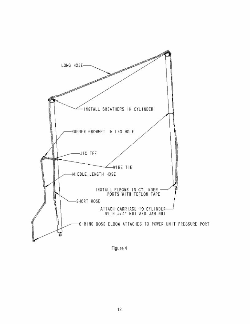
5. Install hydraulic cylinders, fittings, hoses, and cables A. Warning: When attaching hydraulic fittings with pipe threads to the cylinders, use Teflon tape. DO NOT start the Teflon tape closer than 1/8” from the end of the fitting. Failure to comply may cause damage to the hydraulic system. B. Warning: When tightening connections with flared (JIC) fittings, always follow the following tightening instructions. Failure to follow these instructions may result in cracked fittings and / or leaks. * Use the proper size wrench. * The nut portion of the fitting is the only part that should turn during tightening. The flare seat MUST NOT turn. * Screw the fittings together hand tight. * Use the proper size wrench to rotate the nut portion of the fitting 2-1/2 hex flats. * Back the fitting off one full turn. * Again, tighten the fitting hand tight, then rotate the nut portion of the fitting 2-1/2 hex flats.
C. Installthecylinderstotheuprightswith1/2"x4-1/2"Grade8bolt,cylinder bushings, washers, and nut. The port near the rod end of the cylinders should be positioned pointing to the leg’s open side.
D. Remove the plugs and install the hydraulic breathers into the ports at the top of the cylinders.
E. Connect the shortest hydraulic hose to one of the runs on the JIC tee fitting.
F. Connect the longest hydraulic hose to the other run on the JIC tee fitting.
G. ConnecttheremaininghydraulichosetothebranchontheJICteefitting.
H. Installtherubbergrommetintotheholeinthemainsidelegextension.
I. Connect a male pipe thread to male JIC elbow to the port near the rod end of each cylinder. The fittings should face away from the leg’s baseplate. J. Connect the free end of the shortest hydraulic hose to the elbow on the cylinder in the mainside leg. This connection should be hand-tight only.
K. Feed the shortest remaining hose through the rubber grommet, from inside the leg out. Feed this hose down through the hose guide welded to the outside of the leg. This hose will attach to the power unit.
L. Feed the long hose through the upright tube along the cylinder.
12
Figure 4
13
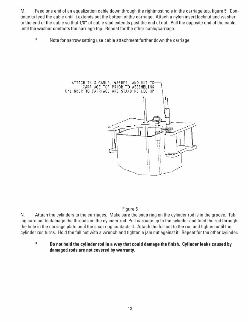
M. Feed one end of an equalization cable down through the rightmost hole in the carriage top, figure 5. Con-tinue to feed the cable until it extends out the bottom of the carriage. Attach a nylon insert locknut and washer to the end of the cable so that 1/8” of cable stud extends past the end of nut. Pull the opposite end of the cable until the washer contacts the carriage top. Repeat for the other cable/carriage.
* Note for narrow setting use cable attachment further down the carriage.
Figure 5N. Attach the cylinders to the carriages. Make sure the snap ring on the cylinder rod is in the groove. Tak-ing care not to damage the threads on the cylinder rod. Pull carriage up to the cylinder and feed the rod through the hole in the carriage plate until the snap ring contacts it. Attach the full nut to the rod and tighten until the cylinderrodturns.Holdthefullnutwithawrenchandtightenajamnutagainstit.Repeatfortheothercylinder.
* Do not hold the cylinder rod in a way that could damage the finish. Cylinder leaks caused by damaged rods are not covered by warranty.

14
6. Carriage Placement. Disengage the latch by pulling out the latch on the column, figure 6. Slide the car-riagetotheleg’sbaseplate.Engagethelatchbyreleasingthelatch.Slidethecarriageupuntilthefirst"click"isheard. Repeat the process for the other carriage.
Pull LatchOut
Figure 6
7. Leg positioning and anchoring A. Raise the Mainside leg only and position it where it is to be secured, figure 2.
B. Theanchorboltsmustbeinstalledatleast5-11/16"fromanyedgeorseamintheconcrete.
C. The concrete must be at least 4-1/4” thick with a compressive strength of 3,000 psi.
D. Using the leg as a template, drill the anchor bolt holes for the Mainside Leg Only!!
* UseahammerdrillwithaCarbidetip,3/4"diameter,soliddrillbit.Thebittipdiameter shouldbetoANSIStandardB95.12-1977.(.775"to.787"). * Keep the drill perpendicular to the floor while drilling. * Let the drill do the work. Do not apply excessive pressure. * Lift the drill up and down to remove dust and reduce binding. * Drill the hole completely through the slab. * Clean the dust from the hole.
15
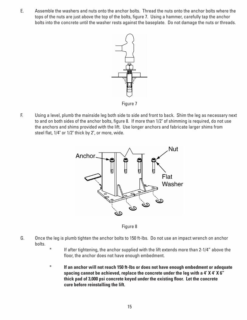
E. Assemble the washers and nuts onto the anchor bolts. Thread the nuts onto the anchor bolts where the tops of the nuts are just above the top of the bolts, figure 7. Using a hammer, carefully tap the anchor bolts into the concrete until the washer rests against the baseplate. Do not damage the nuts or threads.
Figure 7
F. Using a level, plumb the mainside leg both side to side and front to back. Shim the leg as necessary next toandonbothsidesoftheanchorbolts,figure8.Ifmorethan1/2"ofshimmingisrequired,donotuse the anchors and shims provided with the lift. Use longer anchors and fabricate larger shims from steelflat,1/4"or1/2"thickby2",ormore,wide.
Figure 8
G. Oncethelegisplumbtightentheanchorboltsto150ft-lbs.Donotuseanimpactwrenchonanchor bolts. * If after tightening, the anchor supplied with the lift extends more than 2-1/4” above the floor, the anchor does not have enough embedment.
* If an anchor will not reach 150 ft-lbs or does not have enough embedment or adequate spacing cannot be achieved, replace the concrete under the leg with a 4’ X 4’ X 6” thick pad of 3,000 psi concrete keyed under the existing floor. Let the concrete cure before reinstalling the lift.

16
H. Rechecktheleg’splumbnessaftertighteningtheanchorbolts.Addshimsifnecessary.
I. Raise the offside leg and position it where it is to be located, figure 2. Do not drill holes for anchors.
8. Overhead Switch Bar
A. Single Phase
* Using(2)1/4-20X1/2HHCSand(2)1/4-20FlangedLockNutsattachtheoverheadswitchassem- bly to the overhead beam as shown in figure 9.
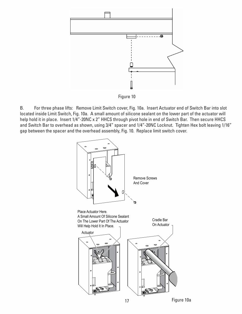
Figure 9 Slide the end of the padded switchbar without a mounting hole in it through the slot in the overhead switch assembly. Connect the padded switchbar to the inside hole in the overhead beam using a cylindrical spacer,1/4-20X1-3/4HHCS,andFlangedNut,figure10.
17
Figure 10
B. For three phase lifts: Remove Limit Switch cover, Fig. 10a. Insert Actuator end of Switch Bar into slot located inside Limit Switch, Fig. 10a. A small amount of silicone sealant on the lower part of the actuator will helpholditinplace.Insert1/4”-20NCx2”HHCSthroughpivotholeinendofSwitchBar.ThensecureHHCSandSwitchBartooverheadasshown,using3/4”spacerand1/4”-20NCLocknut.TightenHexboltleaving1/16”gap between the spacer and the overhead assembly, Fig. 10. Replace limit switch cover.
Place Actuator Here.A Small Amount Of Silicone SealantOn The Lower Part Of The ActuatorWill Help Hold It In Place.
Cradle Bar On Actuator
Actuator
Remove ScrewsAnd Cover
Figure 10a
18
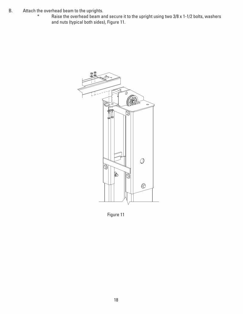
B. Attach the overhead beam to the uprights. * Raise the overhead beam and secure it to the upright using two 3/8 x 1-1/2 bolts, washers and nuts (typical both sides), Figure 11.
Figure 11
19
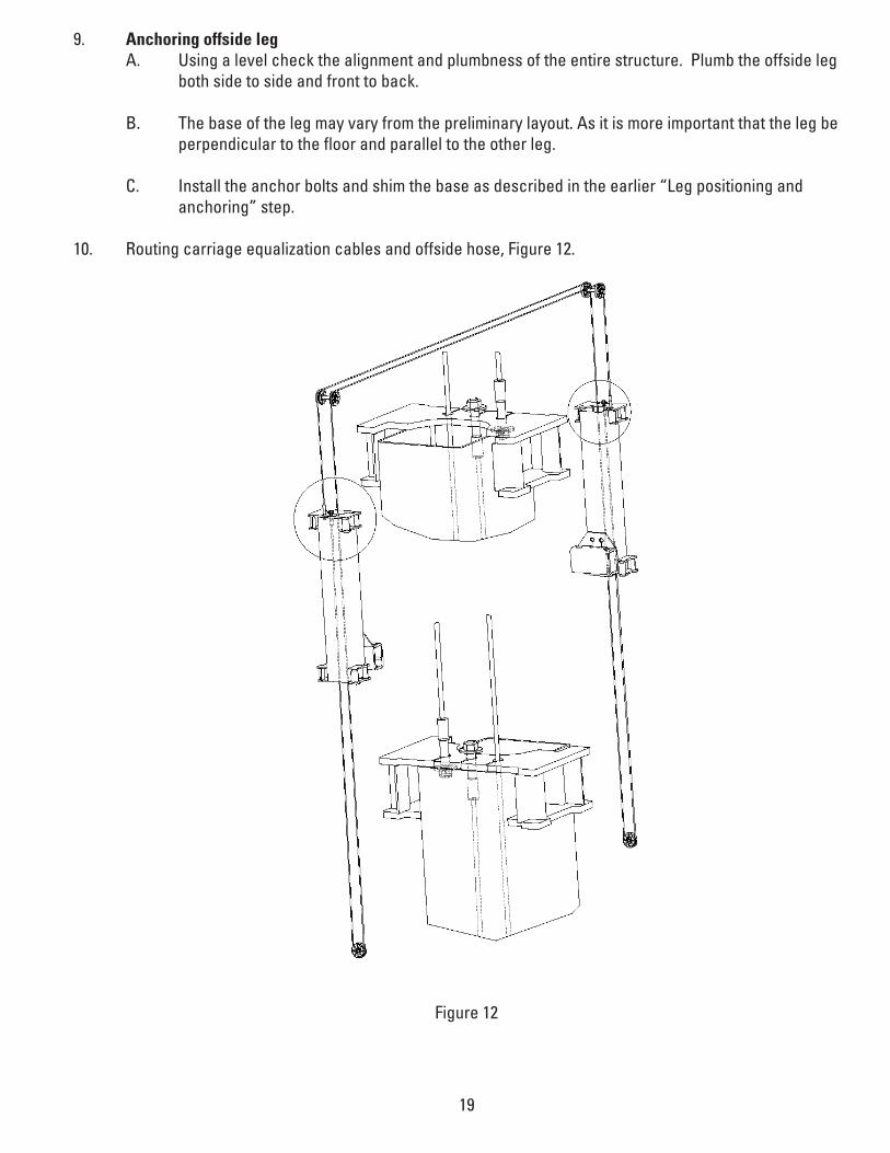
9. Anchoring offside leg A. Using a level check the alignment and plumbness of the entire structure. Plumb the offside leg both side to side and front to back.
B. The base of the leg may vary from the preliminary layout. As it is more important that the leg be perpendicular to the floor and parallel to the other leg.
C. Installtheanchorboltsandshimthebaseasdescribedintheearlier“Legpositioningand anchoring” step.
10. Routing carriage equalization cables and offside hose, Figure 12.
Figure 12

20
A. The carriages should be resting on the same safety rack tooth. Measure the height above the baseplate foreachcarriage.Themeasurementsshouldbewithin3/8"ofeachother.Makeanoteofthe two measurements.
B. One end of each cable should already be attached to each carriage. Feed the other end of the cable up through the top of the leg as shown. * around the sheaves on the uprights,
» (while in the elevated position, feed the offside hose through the hose guides welded to the top of the overhead tube and down through the offside upright tube.)
* feed cable through the clearance hole in the left hand corner of the carriage top, * around the sheave at the bottom of the leg, * through the hole in the center of the carriage top.
C. Secure the cable end to the carriage top with a nylon insert nut and washer. Do not tighten the cable at this time.
D. Repeat the process for the other cable, taking care not to cross them.
E. Take out the slack, but do not tighten, in both cables by turning down the nuts on the top of each carriage top. Use vise grips to hold the cable end. Be very careful not to damage the threads.
F. The carriages must remain at the same lock position while the cables are being tightened. Overtighten- ing of one cable could raise the carriage in the opposite leg and cause the carriage safety latches to be out of sync.
G. Alternatelytightenthecablenutsatbothcarriagesuntilthecablesaretightened.Correcttensionin the cables is indicated by being able to pull the cables together with approximately 15 pounds of effort at their midpoint in the leg.
H. Measureandcomparethecarriageheightstotheearliermeasurement.Checkthatthesafetylockswill not disengage to verify that neither carriage has been raised. If a carriage has been raised more than1/8",loosenthecablesandrepeattheprocedure.
I. If the cables are installed correctly, both carriages will raise together. If equipment capable of lifting the carriages is readily available, lift one of them just enough to the disengage locks and carefully lower to the ground. This will simplify the cylinder bleeding procedure.

21
11. Locking Latch Cable
A) Install latch cable sheave and retaining rings in upper slot of power unit column as shown, Fig. 14.
B) Slip loop end of cable over end of shoulder screw on right side latch control plate, Fig. 14.
C) Feed the other end of the cable through the latch cable sheave slot making sure that the cable is running under the bottom side of the latch cable sheave and inside the right column, Fig. 14.
D) Attach latch cable conduit guide brackets to overhead as shown, Fig. 13 & Fig. 13a. Always use the holes on theapproachsideofthelift.HHCSshouldbeinholenearestthecenteroftheoverhead,Fig.13a.
E) Route cable up inside column and through the latch cable guide, Fig. 13a & Fig. 15.IMPORTANT Usingwiretiesprovided,tieoffcableguidetocolumnextensionasshown,Fig.13a.Guidemust
beattachedinholeclosesttotheoutsideedgeofthecolumnontheNON-APPROACHside.
F) Continue routing cable to the left column latch cable guide, Fig. 13 & Fig. 15, routing the cable through the left column latch cable guide, Fig. 13.
IMPORTANT Usingwiretiesprovided,tieoffcableguidetocolumnextensionasshown,Fig.13a.GuidemustbeattachedinholeclosesttotheoutsideedgeofthecolumnontheNON-APPROACHside.
G) Bringthecabledowninsidetheleftcolumnandfeedtheendofthecablethroughthelowerlatchcablesheave slot so that the cable is now back outside the column, Fig. 16.
H) Installlatchcablesheaveandretainingringsinlowerslotofnon-powerunitcolumnasshown,Fig.16.
I) Route cable under the bottom side of the latch cable sheave, Fig. 16.
J) At this point you MUST install the latch handle, jam nut, and right column latch cover Fig. 14 & Fig. 17. Install latch handle ball, Fig. 17.
K) Insert cable in cable clamp along one side, loop around shoulder screw and back down, inserting cable along other side of cable clamp, Fig. 16. Place top back on clamp, barely tightening.
L) Next, pull the control plate down, Fig. 15 & Fig. 16, to eliminate any clearance between the control plate slot and the latch dog pin, Fig. 15.
M) Using Pliers, pull cable tight and secure the clamp close to the shoulder screw. Tighten clamp.

22
APP
ROA
CH
Attach Hose Clamps Here
Attach Latch Cable ConduitGuide Bracket Here. Always
use two holes on approachside of extension to attach bracket. Always put HHCS through hole
closest to center of overhead.
Hose Clamp
Approach Side
M10×1.5×20Lg.HHCSM10×1.5 Esrrated Flanged Locknut
Route Cable GuideThrough Here
1/4-20×1 HHCS1/4-20 Flange Hex Lock Nut
Cable EndBracket
Figure 13
Figure 13a

23
(2) 3/8" Retaining Rings
Latch Cable Sheave
Shoulder Bolt
Install Latch Handle using ahex jam nut to lock in place.
Shoulder Bolt
Cable Clamp
Feed cable up through CableClamp, loop over end of shoulder bolt and feed backdown through Cable Clamp.
(2) 3/8" RetainingRings
Latch Cable Sheave
5/16-18NC x 3/8" lg. PHMS
Latch handle MUST bepositioned horizontialwhere it leaves cover.
Ball Handle
Latch Cable Guide
Right Column
Latch Cable
Notice the clearance removed between Control Plate Slot and Latch Dog Pin.
Figure 14Figure 15
Figure 16
Figure 17
24
12. Mountingthepowerunit.Attachfour5/16"x1-1/4"boltstothehighesttwoandlowesttwoholesinthe mountingbracketwith5/16"plainnuts.Attachthepowerunit,totheseboltsandsecurewith5/16"nylon insert nuts.
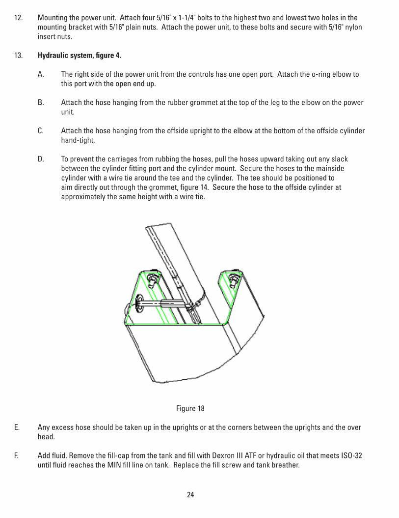
13. Hydraulic system, figure 4.
A. The right side of the power unit from the controls has one open port. Attach the o-ring elbow to this port with the open end up.
B. Attach the hose hanging from the rubber grommet at the top of the leg to the elbow on the power unit. C. Attach the hose hanging from the offside upright to the elbow at the bottom of the offside cylinder hand-tight. D. To prevent the carriages from rubbing the hoses, pull the hoses upward taking out any slack between the cylinder fitting port and the cylinder mount. Secure the hoses to the mainside cylinder with a wire tie around the tee and the cylinder. The tee should be positioned to aim directly out through the grommet, figure 14. Secure the hose to the offside cylinder at approximately the same height with a wire tie.
Figure 18
E. Any excess hose should be taken up in the uprights or at the corners between the uprights and the over head.
F. Add fluid. Remove the fill-cap from the tank and fill with Dexron III ATF or hydraulic oil that meets ISO-32 until fluid reaches the MIN fill line on tank. Replace the fill screw and tank breather.

25
14. Electrical.
A. Single Phase
* Haveacertifiedelectricianestablish208-230V,singlephase,60Hz,20amp,figure19,power supply to motor and overhead switch . * Use separate circuits for each lift. * Singlephasemotorcannotberunon50Hzlinewithoutmodificationsinthemotor.
Three Phase
* Three phase 208-240V, use 20 amp fuse. For three phase 400V and above, use 10 amp fuse, figure 19a.
Figure 19

26Figure 19a
T7T1
T8T2
T9T3
T4
T5
T6
L1
L2
L3
T7 T4T1L1
T8 T5T2L2
T9 T6T3L3
T1
T2
T3
U2
V2
W2
W1
V1
U1
208-240V50/60Hz. 3Ø
440-480V 50/60 Hz. 3Ø380-400V 50 Hz. 3Ø
575V 60 Hz. 3Ø
(4) M5 x 45 PHMS, Plated
(4) M5 x 10 PHMS, PlatedCapacitor Box To Power Unit
Drum SwitchAnd Cover
Re-seal BetweenBox And SpacerWith SiliconeSealer
CapacitorBox
Gasket
Steel Spacer
Capacitor Box AttachmentOption Two
L1
PE
L2L3
135
246 MOTOR
135
246
OVERHEAD SWITCH(WHERE APPLICABLE)
DRUMSWITCH
3 PhaseSupply
Capacitor Box AttachmentOption One
L1
PE
L2L3
135
246 MOTOR
157
268
OVERHEAD SWITCH(WHERE APPLICABLE)
DRUMSWITCH
3 PhaseSupply
FOR 3 Ø POWERUNITS: Attach Box using M5 x 10 PHMS, Plated
NOTES:1. Unit not suitable for use in unusual conditions. Contact
Rotary for moisture and dust environment duty unit.2. Control Box must be field mounted to power unit. 3. Motor rotation is counter clockwise from top of motor.
NOTE: Two Different Drum Switches were usedplease select one of the two options below.
Three Phase Power UnitMOTOR OPERATING DATA TABLE - THREE PHASE
LINE VOLTAGE RUNNING MOTOR VOLTAGE RANGE 208-240V 50/60Hz. 197-253V 400V 50Hz. 360-440V 440-480V 50/60Hz. 396V-528V 575V 60Hz. 518V-632V
27
15. Bleeding the hydraulic system, figure 4.
A. Loosen the connections between the hoses and fittings attached to the cylinders. Do not loosen the connections between the fittings and the cylinders themselves.
B. Run the power unit until fluid appears at the mainside cylinder port. Tighten that hose connection.
C. Run the power unit until fluid appears at the offside cylinder port and there is no more air. Tighten that hose connection.
D. Lower the lift to the ground. If the lift is on the safety latches, raise the lift enough to disengage the latches and then lower.
E. If the carriages were on the ground when the bleeding process was begun, no further bleeding is required. If not, repeat the previous steps for bleeding the hydraulic system.
F. Add fluid to the system as previously described.
28
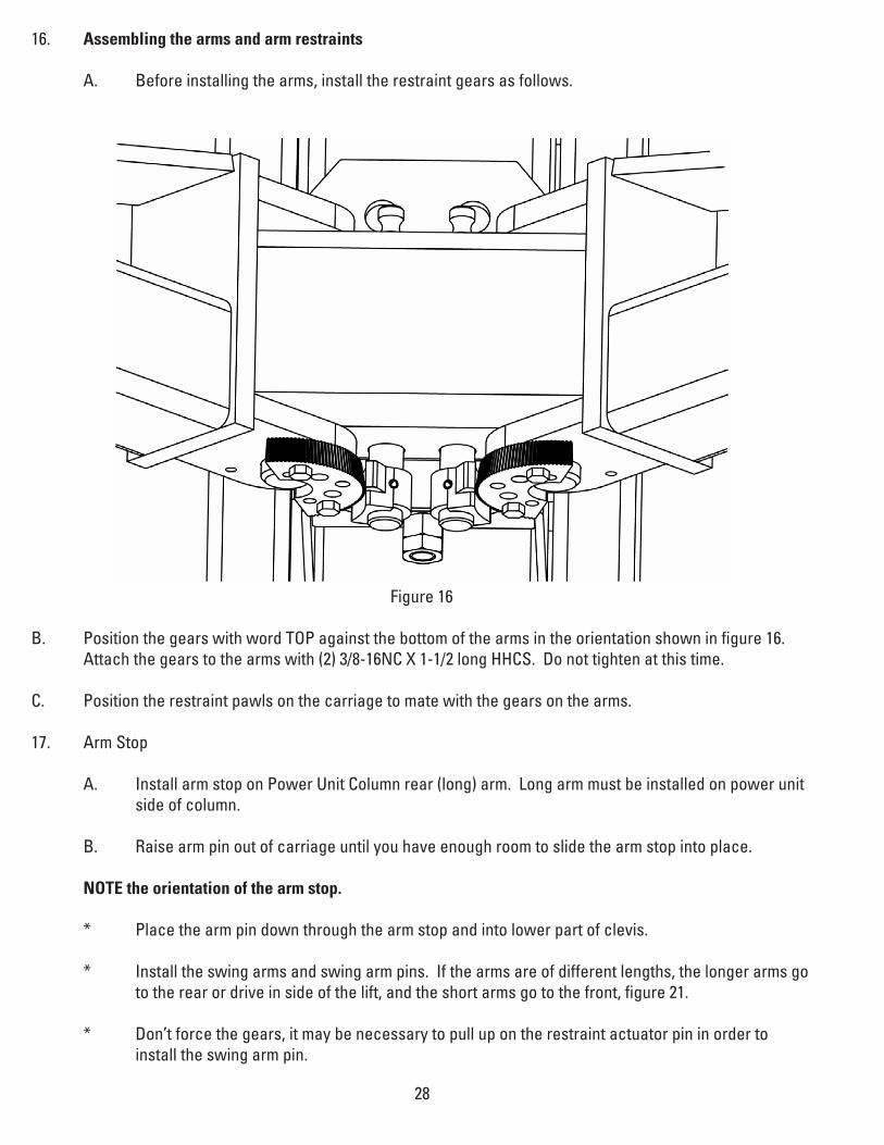
16. Assembling the arms and arm restraints
A. Before installing the arms, install the restraint gears as follows.
Figure 16
B. Position the gears with word TOP against the bottom of the arms in the orientation shown in figure 16. Attachthegearstothearmswith(2)3/8-16NCX1-1/2longHHCS.Donottightenatthistime.
C. Position the restraint pawls on the carriage to mate with the gears on the arms.
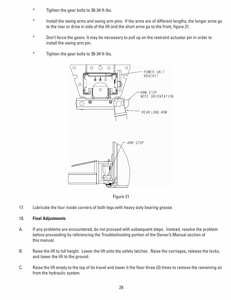
17. Arm Stop
A. Install arm stop on Power Unit Column rear (long) arm. Long arm must be installed on power unit side of column.
B. Raise arm pin out of carriage until you have enough room to slide the arm stop into place.
NOTE the orientation of the arm stop.
* Place the arm pin down through the arm stop and into lower part of clevis.
* Install the swing arms and swing arm pins. If the arms are of different lengths, the longer arms go to the rear or drive in side of the lift, and the short arms go to the front, figure 21.
* Don’t force the gears, it may be necessary to pull up on the restraint actuator pin in order to install the swing arm pin.
29
* Tighten the gear bolts to 30-34 ft-lbs.
* Install the swing arms and swing arm pins. If the arms are of different lengths, the longer arms go to the rear or drive in side of the lift and the short arms go to the front, figure 21. * Don’t force the gears. It may be necessary to pull up on the restraint actuator pin in order to install the swing arm pin. * Tighten the gear bolts to 30-34 ft-lbs.
Figure 21
17. Lubricate the four inside corners of both legs with heavy duty bearing grease.
18. Final Adjustments
A. If any problems are encountered, do not proceed with subsequent steps. Instead, resolve the problem before proceeding by referencing the Troubleshooting portion of the Owner’s Manual section of this manual.
B. Raise the lift to full height. Lower the lift onto the safety latches. Raise the carriages, release the locks, and lower the lift to the ground.
C. Raise the lift empty to the top of its travel and lower it the floor three (3) times to remove the remaining air from the hydraulic system.
30
D. The latches should click together as the lift is being raised.
E. When the carriages are lowered onto the locks, both locks should engage completely.
F. The first time a vehicle is placed on the lift, raise it no higher than three feet. Lower the vehicle onto the safety latches. Raise the lift a few inches and release the locks then lower the vehicle to the floor.
G. Raisethevehicletofullheightandlowerthecarriagesontothesafetylatches.Lowerthevehicletothe floor.
H. Aftercyclingthelifttentimeswithavehicleonit,recheckthetightnessoftheanchorstoatleast90ft- lbs.

31
1 Mainside Overhead Weld NDP10-3000A
2 Offside Overhead Weld NDP10-3000B
3 Stackable Pad Weldment 106605
4 Extension Weld NR10-2000
5 Arm Restraint Gear N2122
6 Arm Restraint Pawl N2121
7 Arm Restraint Actuator Pin 143536
8 Arm Restraint Spring 143537
9 Hose Clamp G3T-8005
10 1/4-20Nylon Insert Hex Nut 9911401
11 1/4 Washer 9911405
12 1/4-20 HHCS ×1/2 Lg 9911421
13 1/4-20 HHCS ×2 Lg 9911481
14 5/16-18 Hex Nut 9911701
15 5/16-18 Nylon Insert Lock Nut 9911703
16 5/16-18×1-1/4HHCS Grade 5 9911751
17 Cable Sheath N618
18 3/8-16NC HHCS 912061
19 1/2-13 Hex Nut 912601
20 1/2-13 Nylon Insert Lock Nut 912603
21 1/2 Washer 912605
22 1/2-13 ×1-3/4 HHCS 912671
23 1/2-13 ×5 HHCS 912791
24 3/4-16 Hex Nut 913602
25 3/4-16 Hex Jam Nut 913611
26 3/4×5-1/2 Anchor Bolt 913828
27
28 Offside Leg Assembly 1070122
29 Offside Leg Weldment NR10-1100
30 Mainside Leg Assembly 1070121
31 Mainside Leg Weldment NR10-1000
32 Carriage Assembly 1070510
33 Carriage Weld NDP10-2000
34 Rear Arm Assembly 1070639
35 Rear Arm Tube Weldment I-DP10-5100
36 Sheave Pin 0970802
37 Cylinder Bushing 0970804
38 Cable End Bracket N619
39 Cylinder Mount/Upright Assembly 1070817
40 Cylinder Mount/Upright Weldment NR10-3000
41 Small Parts Bag NR10-D3
42 Cable Sheave 1070900
43 Single Phase Overhead Switch N413
Section 3 Parts Breakdown
44 Literture Bag 994255
45 Hydraulic Bag NR10-D1
46
47 1/4 Return Line 994212
48 Parts Box
49 Cable and Lock Nut
5/8-11 Nylon Insert Locknut 913303
dia.16mm washer 913206
dia.18mm washer
Cable NR10-4000
50 1-3/8 Snap Ring 991030
51 1/4 Roll Pin ×1-1/2Lg 991060
52 M10×1.5×20Lg.HHCS 41536
53 M10×1.5 Esrrated Flanged Locknut 41655
54 24" Wire Tie 991082
55 Shim 991127
56 Swivel Pad Rubber Insert 991234
57 1/4-20×1-1/4 Elev. Bolt 991243
58 Switch Bar Spacer 991480
59 Overhead Switch Bar,Single Phase 991481
60 3/8NC×1/2Lg.Self-tapping screw 991487
61 1/4-20 Flange Hex Lock Nut 991490
62 Rubber Grommet 991491
63
64 3/4 Klip Ring 991504
65 Single Phase Power Unit P3302
Single Phase Power Unit 50Hz P3398
Three Phase Power Unit P3414
66 Mainside Hose 992220
67 Power Unit Hose 992219
68 Offside Hose NR10-9801-1
69 Cylinder 992328
70 3/8 JIC to 3/8 NPT Elbow 992402
71 3/8" Bushing to 1/4" NPT Bushing
Mainside Return Line Tee
Standard Height Models 992500
Offside Return Line Fitting
Standard Height Models
72 9/16 O-Ring to 3/8 JIC Elbow 992410
73 3/8 JIC Tee ;
74 Swivel Pad Insert Kit 994105
75 2-Post Pressure Fitting Kit 994216

32
76 Stack Swivel Pad Weldment Kit 994256
77 Pad Extension Kit 994257
78 Arm Restraint Gear Kit 994258
79 Rub Block 995120
80 Arm Pin 995430
81 6" Pad Extension 995550
82 3" Pad Extension 995560
83 1-1/2" Pad Extension 996220
84 Left Front Arm Assembly 1070669
85 Left Front Arm Tube Weldment 1070671
86 Right Front Arm Assembly 1070670
87 Right Front Arm Tube Weldment 1070681
88 Rear Arm Slider,Long 1070629
89 Front Inner Arm 1070672
90 Control Box
3 Phase Control Box 208/230V FA7146-1
3 Phase Control Box 480V FA7146-3
91 Middle Arm weld N2220-10Y
92 Mainside Latch Cover PV-1001
93 Offside Latch Cover PV-1002
94 Handle Ball B84-35
95 Latch Handle PV-1007
96
97
98 dia. 20mm Circlip B60-20
99 dia. 20mm Washer B41-20
100 Latch Pin PV-1006
101 Spring PV-1040
102 Spring PV-1009
103 Spacer PV-1015
104 Latch Block PV-1005
105 M6×40mm Spring Pin B51-6×40
106 Control Plate PV-1003
107 Hex Bolt PV-1008
108 M6×16mm Bolt B20-6×16
109 M10 Nut B30-10
110 M6×10mm Bolt B231-6×10
111 Sheave PV-1013
112 dia.
113 Spring PV-1009DC
114 Control Plate PV-1004
115 M6×16mm Bolt B21-6×16
116 1/4-20×1 HHCS 40108
10mm Circlip B60-10

33
53
52
2
1
4
39 40
3642
1753
9
116
61
52
68
61
5813
2122
19
59
43
12
90
79
23
20
69
66
70
73
62
67
33
32
80
8584
60
648
7
516
2928
575674
311
10
18
5
3534
88
22
65
81
82
83
1614 15
4
92
91 89
72
93
94
95
49
96
97
54
26
0331
38

115
112
112
111
111
110
110
109
108
108107
107106
114
105
105104
104
103
103
113
102
101
101
100
10099
9998
98
9594
92
93

NOTES

© August 2009 All rights reserved. CO7378.8 IN60005Rev. B 8/25/2009