1970 , Volume , Issue Dec-1970 - HP Labs · control many kinds of HP digital instruments and...
16
HEWLETT-PACKARDJOURNAL DECEMBER1970 © Copr. 1949-1998 Hewlett-Packard Co.
Transcript of 1970 , Volume , Issue Dec-1970 - HP Labs · control many kinds of HP digital instruments and...
HEWLETT-PACKARD JOURNAL
DECEMBER 1970 © Copr. 1949-1998 Hewlett-Packard Co.
Computing-Counter Measurement Systems Automated measu remen ts and da ta p rocess ing don ' t necessa r i l y requ i re
a compu te r . Sys tems based on the HP compu t i ng coun te r and a new p rog rammer have compu te r capab i l i t i es bu t l ower - than -compu te r cos ts .
By David Martin
IF THE HISTORY OF THE ART AND SCIENCE OF MEASURE MENT could be viewed as a sequence of ages, the current one would have to be called the Age of Automation. Sys tems are everywhere, performing with varying degrees of automation a variety of functions that used to be drudgery for human beings.
The most automated systems have digital computers as system controllers. In these systems, automated measure ments are only a beginning. The computer can be and usually is programmed to perform arithmetic operations to reduce the raw measured data to the most advantage ous form for its ultimate use.
Computing-counter systems are a new type of low-cost computerized instrumentation system. These systems have no computer as such, but instead are built around the HP 5360A Computing Counter1, an instrument which is part computer and part digital measuring instrument. Like computerized systems, computing-counter systems have the ability to make measurements automatically and per form arithmetic operations on the measured data, all un der program control. True, these systems don't have the 'horsepower' of a computerized system. They are, how ever, simple to operate, they have precision measurement capability, and because they contain no computer, their cost in a given application may be much less than a com puterized system designed for the same application.
Fig. 1 is the basic block diagram of a computing-coun ter system. The arithmetic unit of the computing counter provides the mathematical functions add, subtract, multi ply, and divide. The instrument part of the computing counter is called the measurement section.
Programmability is provided by a new instrument, Model 5376A Programmer, which also acts an an inter face between the computing counter and other instru ments or peripheral devices. The programmer has
outputs for time synchronization, delay generation, and integration with the outside world to make a practical, working, measurement system. Most programmer capa bilities are plug-in options. Thus the system configuration can be tailored to fit exactly the requirements of the appli cation. Capabilities not needed are not paid for, but can be added easily in the field if requirements change. The programmer is described in detail in the article on page 7.
â € ¢ T h e M o d e l c o u n t e r c a n a l s o b e p r o g r a m m e d b y i t s k e y b o a r d , M o d e l 5 3 7 5 A ( s e e R e f . 2 ) . F o r s y s t e m s u s e , h o w e v e r , M o d e l 5 3 7 6 A P r o g r a m m e r o f f e r s s e v e r a l a d v a n t a g e s : i t i s r a c k m o u n t a b l e , i t r e t a i n s i t s p r o g r a m w h e n t h e p o w e r g o e s o f f , i t h a s a l a rge r p rog ram memory , and i t has i n te r face fac i l i t i es .
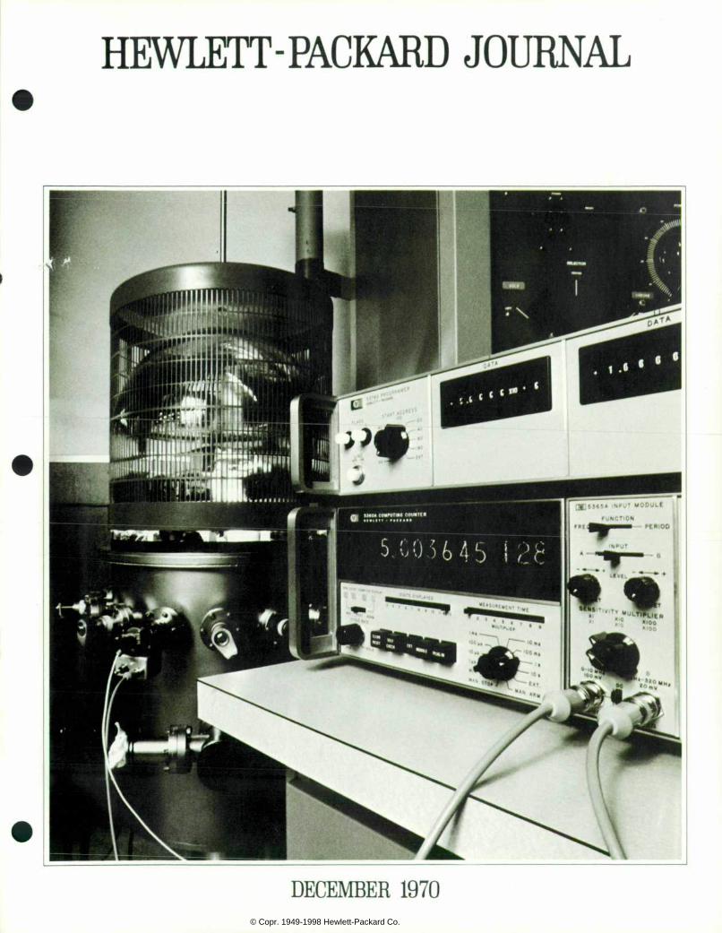
C o v e r : C r y s t a l p l a t i n g i s a t y p i c a l p r o c e s s - c o n t r o l a p p l i ca t ion fo r the 5360 A Com p u t i n g C o u n t e r a n d i t s n e w P r o g r a m m e r , M o d e l 5 3 7 6 A ( o n t o p o f t h e c o m p u t i n g c o u n t e r ) . S e e p a g e 5 f o r a m o r e c o m p l e t e d e s c r i p t i o n . O t h e r a p p l i c a t i o n s f o r t h e
c o m p u t i n g c o u n t e r a n d p r o g r a m m e r a r e i n d a t a reduc t i on and s ta t i s t i ca l ana lys i s .
In this Issue:
C o m p u t i n g - C o u n t e r M e a s u r e m e n t S y s t e m s , b y D a v i d M a r t i n p a g e 2
Prog rammer I s Key to Compu t i ng - C o u n t e r S y s t e m s , b y E r i c M . I n g - m a n . . . page 7
M e a s u r i n g N o i s e a n d L e v e l O n I n t e r n a t i o n a l T e l e p h o n e S y s t e m s , b y J i m P l u m b a n d J a c q u e s H o l t - z i n g e r p a g e 1 3
P R I N T E D I N U . S . A . O H E W L
© Copr. 1949-1998 Hewlett-Packard Co.
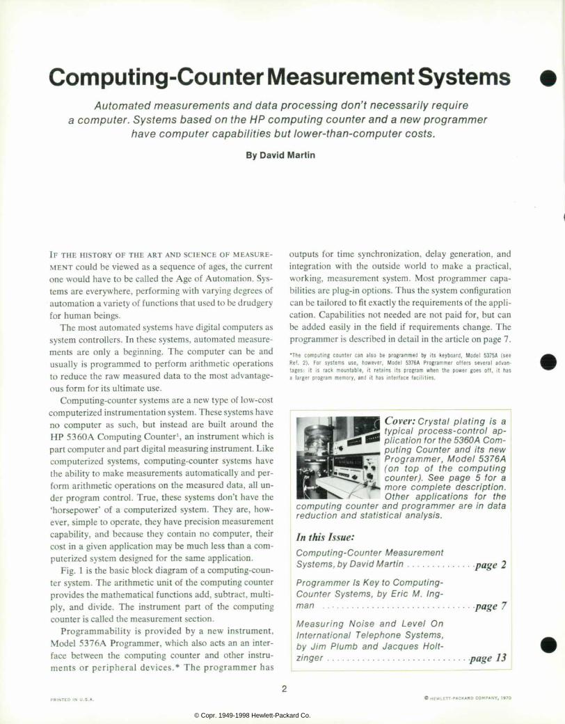
F i g . 1 . C o m p u t i n g - c o u n t e r s y s t e m s , l i k e c o m p u t e r i z e d s y s t e m s , c a n m a k e m e a s u r e m e n t s a n d a r i t h m e t i c a l l y man ipu la te t he da ta resu l t i ng f r om the measu remen ts , a l l u n d e r p r o g r a m c o n t r o l . A p p l i c a t i o n s a r e i n d a t a r e d u c t i o n , s t a t i s t i c a l a n a l y s i s , p r o c e s s c o n t r o l .
Measurement Capabi l i t ies By itself, the computing counter measures frequencies
between 0.01 Hz and 320 MHz directly, with 11-digit precision. It can also measure the time between two events to a resolution of 100 picoseconds, about the time it takes light to travel one inch. Its precision is of an order matched only by the most complex of systems, and is the result of making its arithmetic capability an inherent part of its measurement functions.
With an appropriate signal conditioning unit to convert the physical quantity being measured to a form compati ble with the computing counter's measurement section, other kinds of measurements can also be made. Tempera ture, for example, can be measured with microdegree resolution. Phase, inductance, resistance, and other quan tities can be measured by indirect techniques, using the arithmetic capability of the system.
Addition of other instruments to the system, using the
programmer as an interface device, greatly extends the measurement capability of the system. Fitted with its op tional digital input/output facilities, the programmer can control many kinds of HP digital instruments and receive data from them. The digital I/O might be used, for ex ample, to add a digital voltmeter to the system. Digital output is also useful for recording results using a digital printer or other peripheral device.
Another programmer option, a two-channel analog output, can be used to record data on X-Y plotters. Ana log output can also serve as a feedback control signal in process-control applications. Programs
Programs are written in the machine language of the computing-counter system. This language is well docu mented and easy to learn. Programs are implemented by diode arrays or punched card, both of which act as read only memories, retaining their programs when power is turned off or lost.
The maximum program memory is 200 steps long — short by computer standards. However, the machine language is quite efficient so the memory capacity is sufficient for most applications for which this type of sys tem is suited.
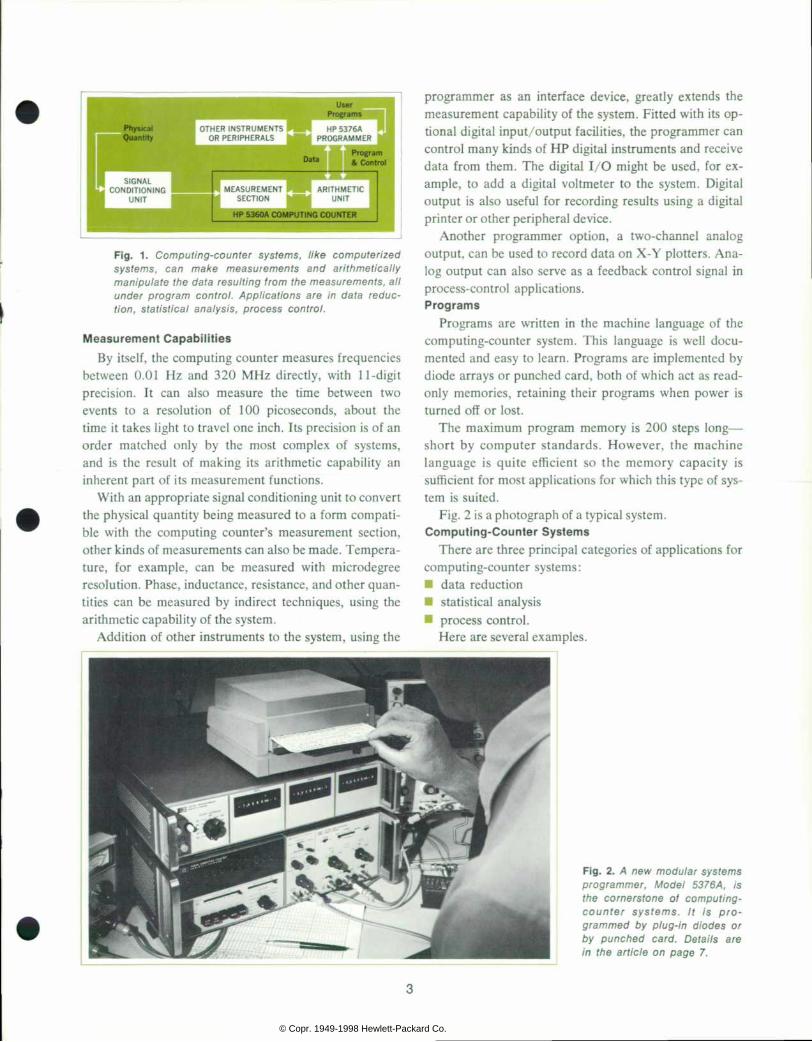
Fig. 2 is a photograph of a typical system. Computing-Counter Systems
There are three principal categories of applications for computing-counter systems: • data reduction • statistical analysis • process control.
Here are several examples.
F i g . 2 . A n e w m o d u l a r s y s t e m s p r o g r a m m e r , M o d e l 5 3 7 6 A , i s t h e c o r n e r s t o n e o f c o m p u t i n g - c o u n t e r s y s t e m s . I t i s p r o g r a m m e d b y p l u g - i n d i o d e s o r b y p u n c h e d c a r d . D e t a i l s a r e i n t h e a r t i c l e o n p a g e 7 .
© Copr. 1949-1998 Hewlett-Packard Co.
Data Reduct ion A good example of the data-reduction capability of
computing-counter systems is the area of nonlinear sys
tems analysis. Most transducers are to some extent non linear. By determining the transducer transfer function y=f(x), measuring the transducer output x, and pro gramming the computing-counter system to solve for f(x), a direct readout of the transducer input can be obtained.
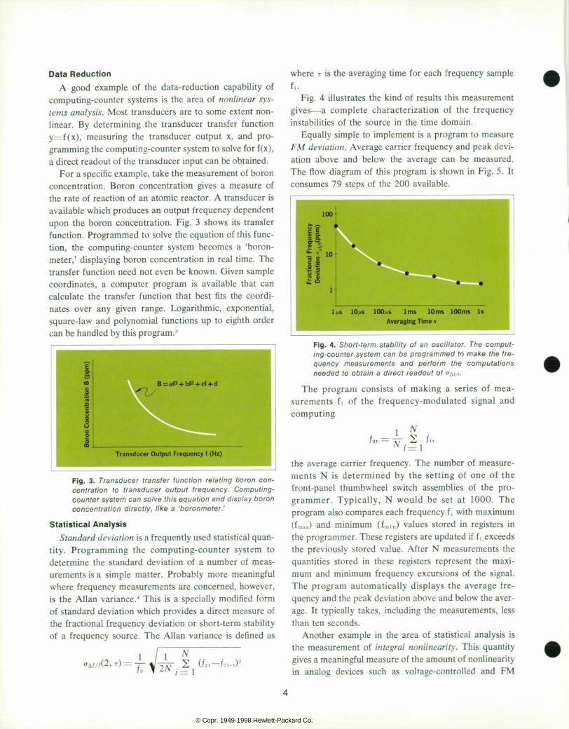
For a specific example, take the measurement of boron concentration. Boron concentration gives a measure of the rate of reaction of an atomic reactor. A transducer is available which produces an output frequency dependent upon the boron concentration. Fig. 3 shows its transfer function. Programmed to solve the equation of this func tion, the computing-counter system becomes a 'boron- meter,' displaying boron concentration in real time. The transfer function need not even be known. Given sample coordinates, a computer program is available that can calculate the transfer function that best fits the coordi nates over any given range. Logarithmic, exponential, square-law and polynomial functions up to eighth order can be handled by this program.3
Transducer Output Frequency f (Hz)
F i g . 3 . T r a n s d u c e r t r a n s f e r f u n c t i o n r e l a t i n g b o r o n c o n c e n t r a t i o n t o t r a n s d u c e r o u t p u t f r e q u e n c y . C o m p u t i n g - coun te r sys tem can so l ve t h i s equa t i on and d i sp lay bo ron c o n c e n t r a t i o n d i r e c t l y , l i k e a ' b o r o n m e t e r . '
Statist ical Analysis Standard deviation is a frequently used statistical quan
tity. Programming the computing-counter system to determine the standard deviation of a number of meas urements is a simple matter. Probably more meaningful where frequency measurements are concerned, however, is the Allan variance.4 This is a specially modified form of standard deviation which provides a direct measure of the fractional frequency deviation or short-term stability of a frequency source. The Allan variance is defined as
where T is the averaging time for each frequency sample It.
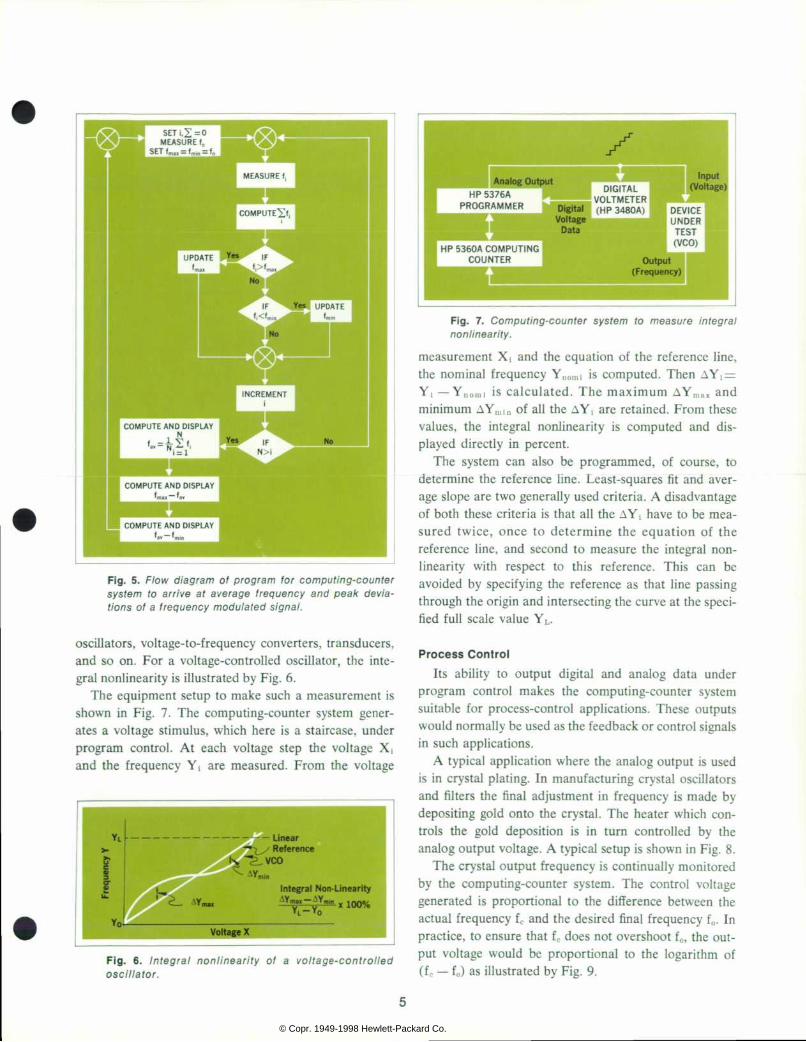
Fig. 4 illustrates the kind of results this measurement gives — a complete characterization of the frequency instabilities of the source in the time domain.
Equally simple to implement is a program to measure FM deviation. Average carrier frequency and peak devi ation above and below the average can be measured. The flow diagram of this program is shown in Fig. 5. It consumes 79 steps of the 200 available.
10»iS 100 MS 1ms 10ms 100ms Is Averaging Time T
1 1
F i g . 4 . S h o r t - t e r m s t a b i l i t y o f a n o s c i l l a t o r . T h e c o m p u t i n g - c o u n t e r s y s t e m c a n b e p r o g r a m m e d t o m a k e t h e f r e q u e n c y m e a s u r e m e n t s a n d p e r f o r m t h e c o m p u t a t i o n s needed to ob ta in a d i rec t readou t o f o& t / , ,
The program consists of making a series of mea surements fi of the frequency-modulated signal and computing
J _ N lav == »T — . I t '
1 = 1
the average carrier frequency. The number of measure ments N is determined by the setting of one of the front-panel thumbwheel switch assemblies of the pro grammer. Typically, N would be set at 1000. The program also compares each frequency f i with maximum (fmax) and minimum (fmln) values stored in registers in the programmer. These registers are updated if f i exceeds the previously stored value. After N measurements the quantities stored in these registers represent the maxi mum and minimum frequency excursions of the signal. The program automatically displays the average fre quency and the peak deviation above and below the aver age. It typically takes, including the measurements, less than ten seconds.
Another example in the area of statistical analysis is the measurement of integral nonlinearity. This quantity gives a meaningful measure of the amount of nonlinearity in analog devices such as voltage-controlled and FM
© Copr. 1949-1998 Hewlett-Packard Co.
SET ¡,2= O MEASURE f
SET U, = fâ„¢ = f .
F i g . 5 . F l o w d i a g r a m o f p r o g r a m l o r c o m p u t i n g - c o u n t e r s y s t e m t o a r r i v e a t a v e r a g e f r e q u e n c y a n d p e a k d e v i a t i o n s o f a f r e q u e n c y m o d u l a t e d s i g n a l .
oscillators, voltage-to-frequency converters, transducers, and so on. For a voltage-controlled oscillator, the inte gral nonlinearity is illustrated by Fig. 6.
The equipment setup to make such a measurement is shown in Fig. 7. The computing-counter system gener ates a voltage stimulus, which here is a staircase, under program control. At each voltage step the voltage X¡ and the frequency YI are measured. From the voltage
D I G I T A L
P R O G R A M M E R D i g i t a l ( H P 3 4 8 0 A ) V o l t a g e
D a t a
H P 5 3 6 0 A C O M P U T I N G C O U N T E R
F ig . 6 . I n t eg ra l non l i nea r i t y o f a vo l t age -con t ro l l ed osci l la tor .
Fig. 7. Comput ing-counter system to measure integral nonlinearity.
measurement X¡ and the equation of the reference line, the nominal frequency Ynomi is computed. Then AY¡ = YI — Ynoml is calculated. The maximum AYmax and minimum AYmin of all the AY¡ are retained. From these values, the integral nonlinearity is computed and dis played directly in percent.
The system can also be programmed, of course, to determine the reference line. Least-squares fit and aver age slope are two generally used criteria. A disadvantage of both these criteria is that all the AYi have to be mea sured twice, once to determine the equation of the reference line, and second to measure the integral non- linearity with respect to this reference. This can be avoided by specifying the reference as that line passing through the origin and intersecting the curve at the speci fied full scale value YL.
Process Control Its ability to output digital and analog data under
program control makes the computing-counter system suitable for process-control applications. These outputs would normally be used as the feedback or control signals in such applications.
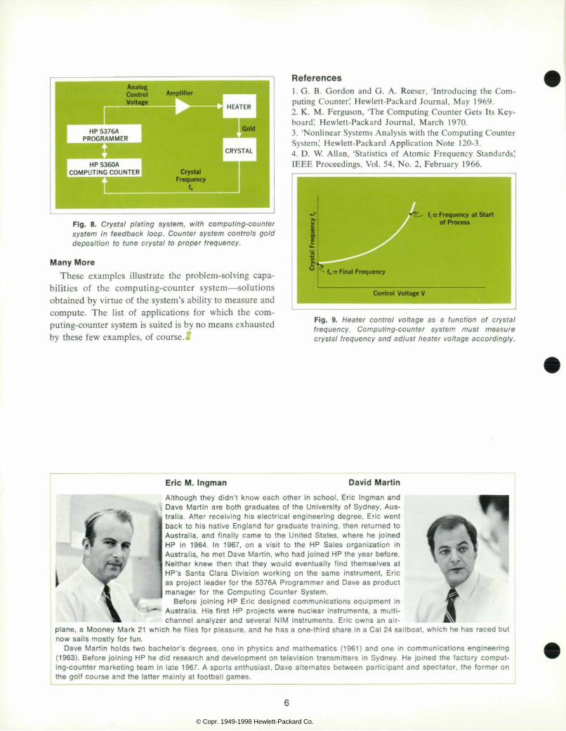
A typical application where the analog output is used is in crystal plating. In manufacturing crystal oscillators and filters the final adjustment in frequency is made by depositing gold onto the crystal. The heater which con trols the gold deposition is in turn controlled by the analog output voltage. A typical setup is shown in Fig. 8.
The crystal output frequency is continually monitored by the computing-counter system. The control voltage generated is proportional to the difference between the actual frequency fc and the desired final frequency f0. In practice, to ensure that fc does not overshoot f0, the out put voltage would be proportional to the logarithm of (fc — f0) as illustrated by Fig. 9.
© Copr. 1949-1998 Hewlett-Packard Co.
HP 5360A COMPUTING COUNTER
F i g . 8 . C r y s t a l p l a t i n g s y s t e m , w i t h c o m p u t i n g - c o u n t e r s y s t e m i n f e e d b a c k l o o p . C o u n t e r s y s t e m c o n t r o l s g o l d d e p o s i t i o n t o t u n e c r y s t a l t o p r o p e r f r e q u e n c y .
Many More These examples illustrate the problem-solving capa
bilities of the computing-counter system — solutions obtained by virtue of the system's ability to measure and compute. The list of applications for which the com puting-counter system is suited is by no means exhausted by these few examples, of course. 5
References 1 . G. B. Gordon and G. A. Reeser, 'Introducing the Com puting Counter; Hewlett-Packard Journal, May 1969. 2. K. M. Ferguson, The Computing Counter Gets Its Key board; Hewlett-Packard Journal, March 1970. 3. 'Nonlinear Systems Analysis with the Computing Counter System; Hewlett-Packard Application Note 120-3. 4. D. W. Allan, 'Statistics of Atomic Frequency Standards; IEEE Proceedings, Vol. 54, No. 2, February 1966.
F i g . 9 . H e a t e r c o n t r o l v o l t a g e a s a f u n c t i o n o f c r y s t a l f r e q u e n c y . C o m p u t i n g - c o u n t e r s y s t e m m u s t m e a s u r e c r y s t a l f r e q u e n c y a n d a d j u s t h e a t e r v o l t a g e a c c o r d i n g l y .
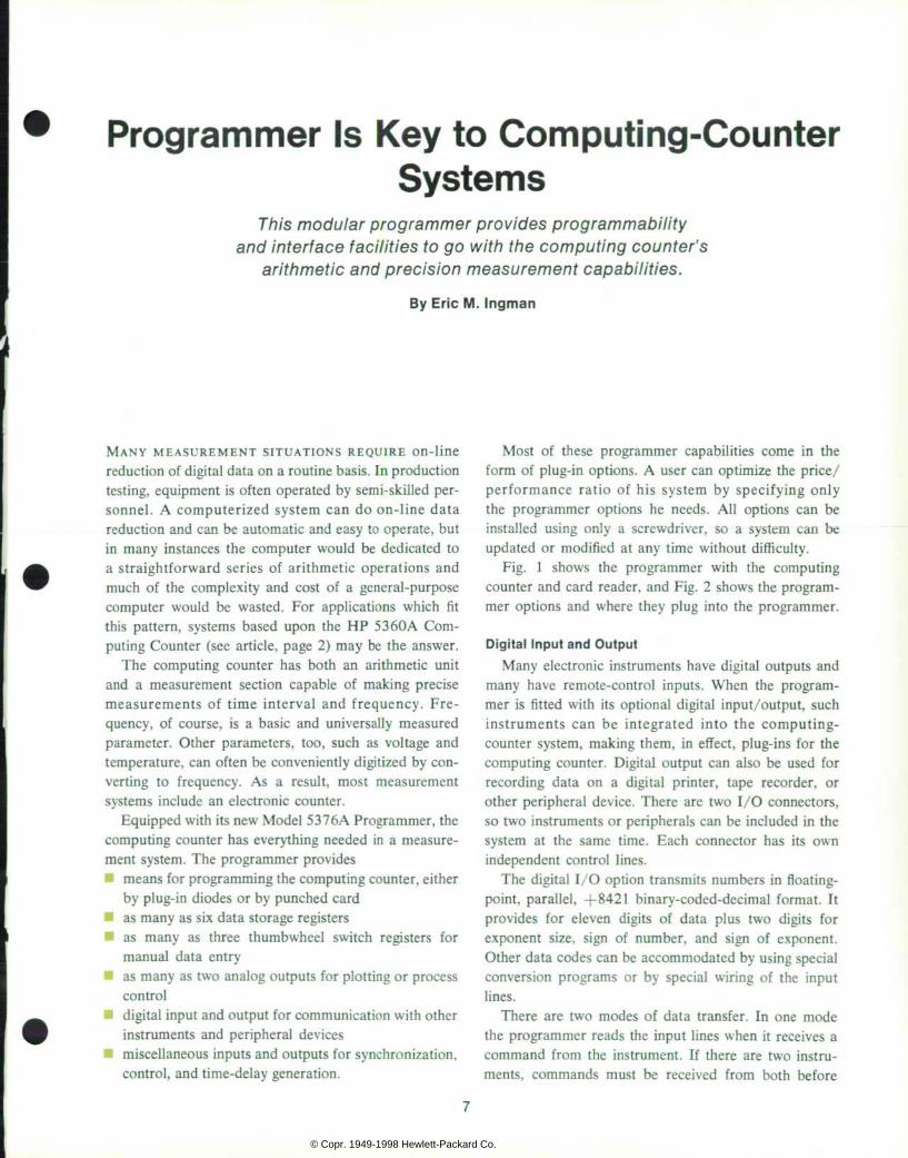
Eric M. Ingman David Mart in
A l t h o u g h t h e y d i d n ' t k n o w e a c h o t h e r i n s c h o o l , E r i c I n g m a n a n d D a v e M a r t i n a r e b o t h g r a d u a t e s o f t h e U n i v e r s i t y o f S y d n e y , A u s t r a l i a . A f t e r r e c e i v i n g h i s e l e c t r i c a l e n g i n e e r i n g d e g r e e , E r i c w e n t b a c k t o h i s n a t i v e E n g l a n d f o r g r a d u a t e t r a i n i n g , t h e n r e t u r n e d t o A u s t r a l i a , a n d f i n a l l y c a m e t o t h e U n i t e d S t a t e s , w h e r e h e j o i n e d
^ C " H P i n 1 9 6 4 . I n 1 9 6 7 , o n a v i s i t t o t h e H P S a l e s o r g a n i z a t i o n i n Aus t ra l i a , he me t Dave Mar t i n , who had j o i ned HP the yea r be fo re . N e i t h e r k n e w t h e n t h a t t h e y w o u l d e v e n t u a l l y f i n d t h e m s e l v e s a t H P ' s S a n t a C l a r a D i v i s i o n w o r k i n g o n t h e s a m e i n s t r u m e n t , E r i c
' â € ¢ a s p r o j e c t l e a d e r f o r t h e 5 3 7 6 A P r o g r a m m e r a n d D a v e a s p r o d u c t m a n a g e r f o r t h e C o m p u t i n g C o u n t e r S y s t e m .
B e f o r e j o i n i n g H P E r i c d e s i g n e d c o m m u n i c a t i o n s e q u i p m e n t i n A u s t r a l i a . H i s f i r s t H P p r o j e c t s w e r e n u c l e a r i n s t r u m e n t s , a m u l t i c h a n n e l a n a l y z e r a n d s e v e r a l N I M i n s t r u m e n t s . E r i c o w n s a n a i r
p lane, sai lboat , Mooney Mark 21 which he f l ies for p leasure, and he has a one-th i rd share ¡n a Cal 24 sai lboat , which he has raced but now sa i l s mos t l y f o r f un .
Dave mathemat ics ho lds two bache lo r ' s degrees , one in phys ics and mathemat ics (1961) and one in commun ica t ions eng ineer ing ( 1 9 6 3 ) . j o i n e d j o i n i n g H P h e d i d r e s e a r c h a n d d e v e l o p m e n t o n t e l e v i s i o n t r a n s m i t t e r s i n S y d n e y . H e j o i n e d t h e f a c t o r y c o m p u t i n g - c o u n t e r m a r k e t i n g t e a m i n l a t e 1 9 6 7 . A s p o r t s e n t h u s i a s t , D a v e a l t e r n a t e s b e t w e e n p a r t i c i p a n t a n d s p e c t a t o r , t h e f o r m e r o n t he go l f cou r se and t he l a t t e r ma in l y a t f oo tba l l games .
© Copr. 1949-1998 Hewlett-Packard Co.
Programmer Is Key to Computing-Counter Systems
Th is modu la r p rog rammer p rov ides p rog rammab i l i t y and in te r face fac i l i t i es to go w i th the comput ing coun te r ' s
a r i thmet i c and p rec is ion measurement capab i l i t i es .
By Eric M. Ingman
MANY MEASUREMENT SITUATIONS REQUIRE on-line reduction of digital data on a routine basis. In production testing, equipment is often operated by semi-skilled per sonnel. A computerized system can do on-line data reduction and can be automatic and easy to operate, but in many instances the computer would be dedicated to a straightforward series of arithmetic operations and much of the complexity and cost of a general-purpose computer would be wasted. For applications which fit this pattern, systems based upon the HP 5 3 60 A Com puting Counter (see article, page 2) may be the answer.
The computing counter has both an arithmetic unit and a measurement section capable of making precise measurements of time interval and frequency. Fre quency, of course, is a basic and universally measured parameter. Other parameters, too, such as voltage and temperature, can often be conveniently digitized by con verting to frequency. As a result, most measurement systems include an electronic counter.
Equipped with its new Model 5376A Programmer, the computing counter has everything needed in a measure ment system. The programmer provides • means for programming the computing counter, either
by plug-in diodes or by punched card as many as six data storage registers
• as many as three thumbwheel switch registers for manual data entry
• as many as two analog outputs for plotting or process control
• digital input and output for communication with other instruments and peripheral devices miscellaneous inputs and outputs for synchronization, control, and time-delay generation.
Most of these programmer capabilities come in the form of plug-in options. A user can optimize the price/ performance ratio of his system by specifying only the programmer options he needs. All options can be installed using only a screwdriver, so a system can be updated or modified at any time without difficulty.
Fig. 1 shows the programmer with the computing counter and card reader, and Fig. 2 shows the program mer options and where they plug into the programmer.
Digital Input and Output Many electronic instruments have digital outputs and
many have remote-control inputs. When the program mer is fitted with its optional digital input/output, such instruments can be integrated into the computing- counter system, making them, in effect, plug-ins for the computing counter. Digital output can also be used for recording data on a digital printer, tape recorder, or other peripheral device. There are two I/O connectors, so two instruments or peripherals can be included in the system at the same time. Each connector has its own independent control lines.
The digital I/O option transmits numbers in floating point, parallel, +8421 binary-coded-decimal format. It provides for eleven digits of data plus two digits for exponent size, sign of number, and sign of exponent. Other data codes can be accommodated by using special conversion programs or by special wiring of the input lines.
There are two modes of data transfer. In one mode the programmer reads the input lines when it receives a command from the instrument. If there are two instru ments, commands must be received from both before
© Copr. 1949-1998 Hewlett-Packard Co.
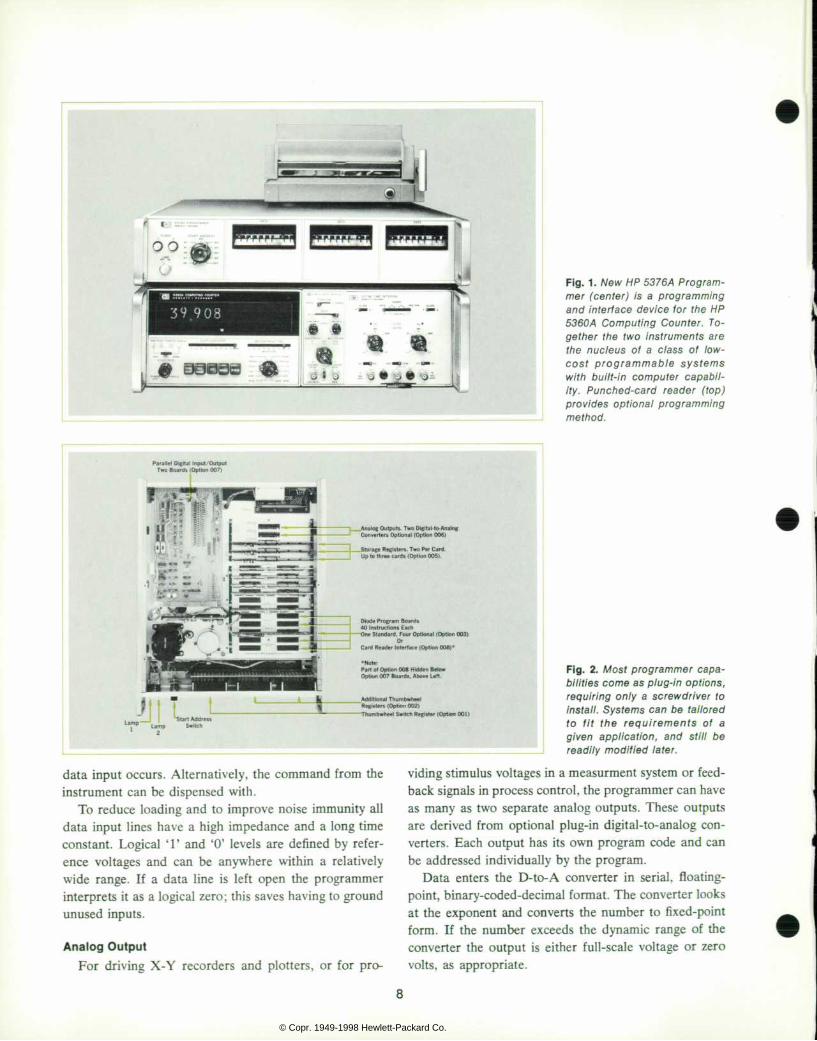
F i g . 1 . N e w H P 5 3 7 6 A P r o g r a m m e r ( c e n t e r ) i s a p r o g r a m m i n g a n d i n t e r f a c e d e v i c e t o r t h e H P 5 3 6 0 A C o m p u t i n g C o u n t e r . T o g e t h e r t h e t w o i n s t r u m e n t s a r e t h e n u c l e u s o f a c l a s s o f l o w - c o s t p r o g r a m m a b l e s y s t e m s w i t h b u i l t - i n c o m p u t e r c a p a b i l i t y . P u n c h e d - c a r d r e a d e r ( t o p ) p r o v i d e s o p t i o n a l p r o g r a m m i n g method .
Para l le l D ig i ta l Input /Output Two Boards (Opt ion 007 )
Converters Opt ional (Opt ion 006)
Storage Registers. Two Per Card Up to three cards (Opt ion 005) .
D iode Program Boards 40 Instruct ions Each
idard. Four Optional (Optk>
Card Reader In te r face (Opt ion 008) *
•Note: Par t o f Opt ion 006 Hidden Below Opt ion 007 Boards. Above Let t .
Addit ional Thumbwheel Registers (Opt ion 002)
ibwheel Switch Register (Opt ion 001)
data input occurs. Alternatively, the command from the instrument can be dispensed with.
To reduce loading and to improve noise immunity all data input lines have a high impedance and a long time constant. Logical T and '0' levels are defined by refer ence voltages and can be anywhere within a relatively wide range. If a data line is left open the programmer interprets it as a logical zero; this saves having to ground unused inputs.
Analog Output For driving X-Y recorders and plotters, or for pro-
F i g . 2 . i V f o s f p r o g r a m m e r c a p a b i l i t i es come as p lug - in op t ions , r e q u i r i n g o n l y a s c r e w d r i v e r t o i ns ta l l . Sys tems can be t a i l o red t o f i t t h e r e q u i r e m e n t s o f a g i v e n a p p l i c a t i o n , a n d s t i l l b e r ead i l y mod i f i ed l a t e r .
viding stimulus voltages in a measurment system or feed back signals in process control, the programmer can have as many as two separate analog outputs. These outputs are derived from optional plug-in digital-to-analog con verters. Each output has its own program code and can be addressed individually by the program.
Data enters the D-to-A converter in serial, floating point, binary-coded-decimal format. The converter looks at the exponent and converts the number to fixed-point form. If the number exceeds the dynamic range of the converter the output is either full-scale voltage or zero volts, as appropriate.
8
© Copr. 1949-1998 Hewlett-Packard Co.
Before conversion to analog form, the binary-coded- decimal numbers are first converted to binary in a BCD- to-binary converter. This converter drives the switches in a conventional 10-bit binary resistor ladder network which does the final conversion to a bipolar analog volt age. The final converter is a thin-film hybrid circuit con taining the switches and thin-film resistor ladder network in one package.
Manual Data Entry Tolerances, limits, and other constants needed in
programs can be entered by means of front-panel thumbwheel switch registers, another programmer option. There can be as many as three of these registers. They can enter positive or negative numbers in floating point form, each number consisting of five digits plus an exponent from —9 to +9.
Extra Storage Registers
In the computing counter are three registers that are used for accumulating measured data and two registers that are available for storing data and intermediate results of programs. Complex programs may require more stor age registers. The programmer can provide as many as six additional registers. All are optional and they come in pairs, two registers on a plug-in printed-circuit board.
Lamps and External Control On the front panel of the programmer are two lamps
which are under program control. They are useful for such things as alerting operators or indicating whether a device has passed or failed a test. Rear-panel elec trical outputs indicate whether the lamps are on or off. The lamps and outputs are standard, not optional.
Also standard is a rear-panel connector at which
several outputs are available. There are four lines which carry signals to control external devices. Sixteen differ ent codes can be generated under program control and carried by these lines. Two other lines indicate whether the two front-panel lamps are on or off. Another output is a synchronization signal for the control of system timing.
Along with these outputs, several input lines are also available at the same connector. There are remote hold- off inputs useful in time-delay generation and in system timing, and remote inputs for selecting program starting addresses.
Programming Computing-counter systems are easy to program. Pro
gramming consists of listing the type and sequence of instructions that will cause the system to perform a given task, and then entering these instructions into the pro grammer using either plug-in diodes or a punched card.
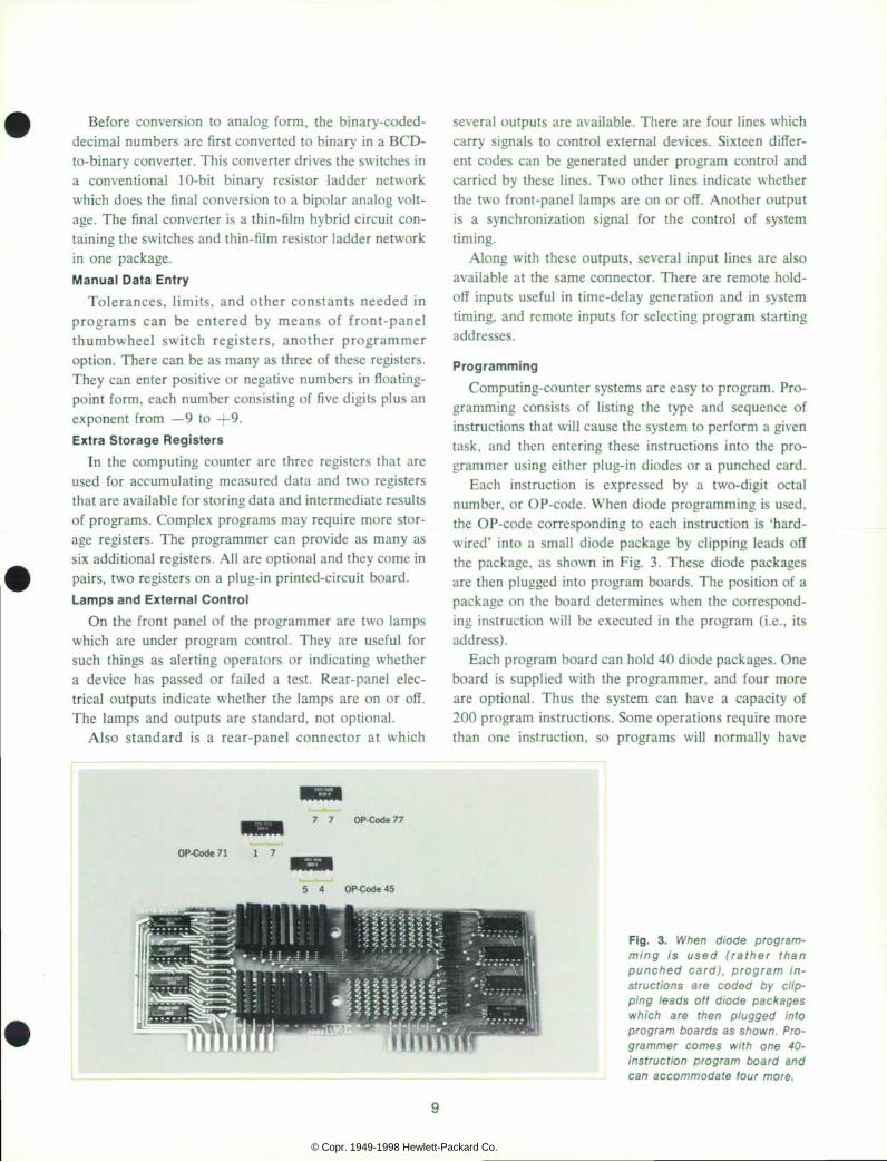
Each instruction is expressed by a two-digit octal number, or OP-code. When diode programming is used, the OP-code corresponding to each instruction is 'hard wired' into a small diode package by clipping leads off the package, as shown in Fig. 3. These diode packages are then plugged into program boards. The position of a package on the board determines when the correspond ing instruction will be executed in the program (i.e., its address).
Each program board can hold 40 diode packages. One board is supplied with the programmer, and four more are optional. Thus the system can have a capacity of 200 program instructions. Some operations require more than one instruction, so programs will normally have
7 7 O P - C o d e 7 7
O P - C o d e 7 1 1 7
5 4 O P - C o d e 4 5
F i g . 3 . W h e n d i o d e p r o g r a m m i n g i s u s e d ( r a t h e r t h a n p u n c h e d c a r d ) , p r o g r a m i n s t r u c t i o n s a r e c o d e d b y c l i p p i n g l e a d s o f f d i o d e p a c k a g e s w h i c h a r e t h e n p l u g g e d i n t o p r o g r a m b o a r d s a s s h o w n . P r o g r a m m e r c o m e s w i t h o n e 4 0 - i n s t r u c t i o n p r o g r a m b o a r d a n d c a n a c c o m m o d a t e f o u r m o r e .
9
© Copr. 1949-1998 Hewlett-Packard Co.
Qg«fy
¿o
SF. tï 1
53
i i i 2 x y
AeT"
75
Ãfi
H - i
i£L
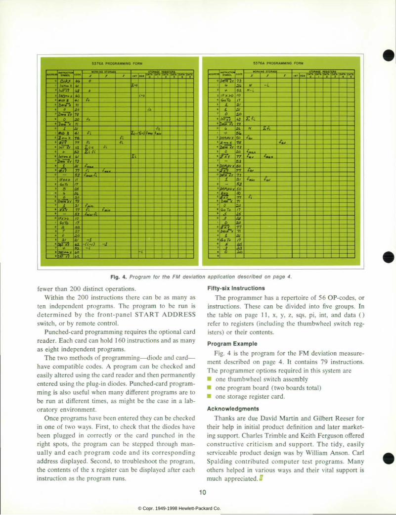
F i g . p a g e 4 . t o r t h e F M d e v i a t i o n a p p l i c a t i o n d e s c r i b e d o n p a g e 4 .
fewer than 200 distinct operations. Within the 200 instructions there can be as many as
ten independent programs. The program to be run is determined by the front-panel START ADDRESS switch, or by remote control.
Punched-card programming requires the optional card reader. Each card can hold 1 60 instructions and as many as eight independent programs.
The two methods of programming — diode and card — have compatible codes. A program can be checked and easily altered using the card reader and then permanently entered using the plug-in diodes. Punched-card program ming is also useful when many different programs are to be run at different times, as might be the case in a lab oratory environment.
Once programs have been entered they can be checked in one of two ways. First, to check that the diodes have been plugged in correctly or the card punched in the right spots, the program can be stepped through man ually and each program code and its corresponding address displayed. Second, to troubleshoot the program, the contents of the x register can be displayed after each instruction as the program runs.
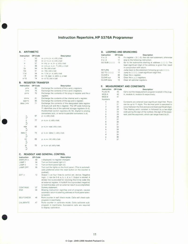
Fifty-six Instructions The programmer has a repertoire of 56 OP-codes, or
instructions. These can be divided into five groups. In the table on page 11, x, y, z, sqs, pi, int, and data () refer to registers (including the thumbwheel switch reg isters) or their contents.
Program Example Fig. 4 is the program for the FM deviation measure
ment described on page 4. It contains 79 instructions. The programmer options required in this system are • one thumbwheel switch assembly • one program board (two boards total) • one storage register card.
Acknowledgments Thanks are due David Martin and Gilbert Reeser for
their help in initial product definition and later market ing support. Charles Trimble and Keith Ferguson offered constructive criticism and support. The tidy, easily serviceable product design was by William Anson. Carl Spalding contributed computer test programs. Many others helped in various ways and their vital support is much appreciated.»
10
© Copr. 1949-1998 Hewlett-Packard Co.
11 © Copr. 1949-1998 Hewlett-Packard Co.
S P E C I F I C A T I O N S HP Model 5376A
Systems Programmer
Spec i f i ca t ions app ly on ly when the 5376A Sys tems Programmer is used wi th the 5360A Comput ing Counter .
DESCRIPT ION: The 5376A Sys tems P rog rammer i s a p rog ramming de v ice 5376A the 5360A Comput ing Counter . When programmed, the 5376A enables the 5360A to solve equat ions, where measurements made by the 5 3 6 0 A d i s a p e r i p h e r a l d i g i t a l i n s t r u m e n t a r e t h e v a r i a b l e s , a n d d i s play the solut ion in real t ime.
P R O G R A M M E M O R Y TYPE: Read-on ly memory by d iodes (see Opt ion 003) o r an IBM card
(see Option 008). CAPACITY: Diodes — to 200 program steps maximum in 40 step incre
m e n t s . T h e b a s i c 5 3 7 6 A i s p r o v i d e d w i t h 4 0 p r o g r a m s t e p s . I B M Card — 160 Program Steps.
STARTING ADDRESS: The s ta r t i ng add ress o f a p rog ram i s de f i ned by set t ing of the START ADDRESS swi tch on the 5376A f ront panel . A t c o m p l e t i o n , t h e p r o g r a m a u t o m a t i c a l l y r e t u r n s t o t h e s t a r t i n g address and recyc les through i t again. The START ADDRESS swi tch a l l ows up t o 10 i ndependen t p rog rams , each 20 s teps l ong , t o be insta l led (8 independent programs wi th IBM card) . W i t h t h e S T A R T A D D R E S S a t E X T , t h i s s w i t c h i s r e m o t e l y p r o g rammab le v ia a 4 l i ne d ig i t a l code app l i ed to t he rea r pane l AUX IL IARY INPUT-OUTPUT connector .
FLAGS 1 & 2 : Can be turned on or o f f under program cont ro l . Para l le l e lect r ica l outputs are prov ided f rom the AUXILIARY INPUT-OUTPUT connector.
S T O R A G E M E M O R Y : 1 3 b i t r e a d - w r i t e 1 C s h i f t r e g i s t e r s . S e e O p t i o n 0 0 5 f o r d e t a i l s .
O P E R A T I N G T E M P E R A T U R E : 0 Â ° C t o + 5 0 Â ° C .
P O W E R : 1 1 5 V o r 2 3 0 V Â ± 1 0 % , 5 0 t o 4 0 0 H z , 7 0 W w i t h a l l o p t i o n s included.
DIMENSIONS: 16% in wide, 315/32 In h igh, 16% in deep.
WEIGHT: Net 21 Ibs , sh ipp ing 25 Ibs , 10 oz .
PRICE: $1,350.00 (includes 1 Opt. 003, 40 step program board).
O P T I O N 0 0 1 : I N I T I A L T H U M B W H E E L S W I T C H A S S E M B L Y Used for manual entry of numerical data. NUMBER CAPACITY: ±9.9999x10- ' . F O R M A T : N u m b e r i s f i x e d p o i n t w i t h 5 d i g i t m a x i m u m m a n t i s s a ,
mant issa s ign , exponent and exponent s ign . PRICE: $275.00
O P T I O N 0 0 2 : A D D I T I O N A L T H U M B W H E E L S W I T C H A S S E M B L I E S Same spec i f i ca t ions as Opt ion 001. Up to two Opt ion 002 assembl ies
can be instal led. PRICE: $150.00 each.
O P T I O N 0 0 3 : P R O G R A M B O A R D C o n s i s t s o f a p r o g r a m b o a r d a n d 4 4 d i o d e p a c k a g e a r r a y s . E a c h
d i o d e p a c k a g e a r r a y g i v e s o n e p r o g r a m s t e p . A p r o g r a m b o a r d h a s a max imum capac i ty o f 40 program s teps.
Up to the Opt ion 003 p rogram boards can be ins ta l l ed . Inc lud ing the p rogram board p rov ided w i th the ins t rument , th is g ives a to ta l capac i ty of 200 steps.
PRICE: $350.00 each.
O P T I O N 0 0 4 : P R O G R A M D I O D E S Provides 22 addit ional program diode arrays. PRICE: $65.00
O P T I O N 0 0 5 : R E G I S T E R C A R D One Opt ion 005 reg is ter card conta ins two vo la t i le read-wr i te s torage
reg is ters fo r the s torage o f numer ica l constants or in termedia te resu l ts of a program.
STORAGE REGISTER CAPACITY: Any number In the range ±1 x10->i to ±9.999 999 999X10+". Up to three Opt ion 005 register cards can be instal led.
PRICE: $200.00 each.
O P T I O N 0 0 6 : D I G I T A L - A N A L O G C O N V E R T E R DESCRIPTION: The d ig i ta l -ana log conver te rs p rov ide an ana log ou t
put of d ig i ta l in format ion stored In the 5360A-5376A System. OUTPUT VOLTAGE RANGE: +9 .99 vo l t s to -9 .99 vo l t s . RESOLUTION: 0.01 volt . ACCURACY: 0.2% of full scale at 25°C. SLEW RATE: <20 ms/vo l t . LOAD CURRENT: 2 mA max. TEMPERATURE DRIFT: 1 mV/"C.
Up to two d ig i ta l -ana log conver ters can be ins ta l led. P R I C E : $ 5 0 0 . 0 0 e a c h .
O P T I O N 0 0 7 : P A R A L L E L D I G I T A L I N P U T - O U T P U T Al lows d ig i ta l data s tored in the 5360A-5376A to be output or external
d ig i ta l data to be put in to the 5360A-5376A System. DIGITAL OUTPUT
TYPE: Para l le l 8421 bed , 1 s ta te pos i t i ve . ' 0 ' s ta te +0 .3 V typ ica l , '1 ' s ta te +5 V typ ica l .
FORMAT: Eleven d ig i t mant issa maximum, mant issa s ign, exponent , exponen t s ign . Any number f rom ±1x10-» i to ±9 .999999999 X10+" levels be output. Print commands, hold-offs, reference levels a re compat ib le w i th the HP 5050B Dig i ta l Recorder .
DIGITAL INPUT TYPE: Same as D ig i t a l Ou tpu t . ' 1 ' s t a te mus t d i f f e r f r om ' 0 ' s t a te
by a t least 4 .5 V but no more than 50 V. FORMAT: Same as Digi ta l Output .
D u a l d i g i t a l i s p r o v i d e d , I . e . d u a l d i g i t a l o u t p u t a n d d u a l d i g i t a l i npu t can be ob ta ined . In add i t ion , bo th inpu ts and ou tpu ts can be con nected simultaneously.
PRICE: $600.00.
O P T I O N 0 0 8 : C A R D R E A D E R DESCRIPT ION: Cons i s t s o f an AMP ca rd - reade r and i n te r f ac i ng c i r
cu i t r y t o t he 5376A Sys tems P rog rammer . An a l t e rna t i ve p rog ram m i n g m e t h o d t o O p t i o n 0 0 3 . U s e s a s t a n d a r d I B M c a r d ( 7 % i n x 3 t t In ) .
C a r d s m a y b e p r e p a r e d b y u s i n g t h e W R I G H T M A N U A L C A R D PUNCH. In add i t i on , many va r ie t i es o f mo to r d r i ven ca rd punches c a n b e f o u n d t h r o u g h o u t t h e i n d u s t r y ( f o r e x a m p l e I B M 2 9 C a r d Punch).
P R I C E : $ 2 , 0 9 0 . 0 0
M A N U F A C T U R I N G D I V I S I O N : S A N T A C L A R A D I V I S I O N 5301 Stevens Creek Boulevard Santa Clara, California 95050
1 2
© Copr. 1949-1998 Hewlett-Packard Co.
Measuring Noise And Level On International Telephone Systems
By Jim Plumb and Jacques Holtz inger
IN COUNTRIES WHERE ECONOMIC DEVELOPMENT IS A
MAJOR OBJECTIVE, the need for exchange of information and ideas is increasing at an extraordinary rate. This exchange requires good quality telecommunication channels.
Measurements made to assure quality transmission of telephone and broadcast equipment include measur ing attenuation or gain versus frequency, and measuring nonlinear distortion. Another important measurement is noise power or voltage in the telephone circuits.
Noise Sources in a Transmission System In telephone and high quality audio or video trans
mission systems, besides the traditional amplifier noise, thermal noise and induced ac from power lines or ripple, some other important disturbing sources of noise are: • Crosstalk produced by inductive or capacitive cou
pling between lines in parallel or at junctions, which can be intelligible, unintelligible or either (babble) when from a various number of sources.
• Clicks and scratching noise generated by atmospheric disturbances, autos, neon lights, defective soldered joints or connections.
• Acoustic noise directly coupled into the telephone sets. These many sources of noise affect transmission qual
ity. Evaluating these for the purpose of improving quality requires an objective measurement with a voltmeter. Two new instruments have been designed specifically for mea surements on telephone systems using CCITT (Con sultative Committee on International Telephone and Telegraph) standards. (Systems operating on CCITT standards are outside the U.S. and Canada. Telephone systems in the U.S. and Canada operate on Bell System standards.)
These new instruments are the HP Model 3556A Psophometer, and the HP Model 236A-H10 Telephone Test Oscillator, Fig. 1. Used together, they are a com plete transmission measuring set.
Weight ing Fi l ter Curves and Standards The disturbance which noise causes to telephone users
depends upon various factors which include the sensi tivity of the ear as a function of frequency. Since noise may be intermittent or continuous, appropriate integra tion time of the noise voltage must be defined. A volt meter based upon these considerations will make mean ingful, comparable measurements. This voltmeter, the Psophometer, is an apparatus for the objective measure ment of circuit noise (in Greek, psophos means noise).
The major difference between the Bell System and CCITT standards are in the frequency response curves or weighting curves used to measure commercial tele phone and broadcast or program transmission lines, and in the impedances. Noise interferes with speech trans mission in different ways. Telephone transmission quality also varies from one facility to another. It is necessary, then, to use a weighting response curve representing not only the average frequency response of the handset, tele phone line and human ear, but also an average of these combined different responses.
Tests by the Joint Subcommittee on Development and Research of the Edison Electric Institute and the Bell Telephone System determined the appropriate weighting curves. These tests have been approved by the CCITT, but different weights were given to various frequencies. Thus the weighting curves have slightly different con figurations (Fig. 2).
With these curves, equalizing networks may be con structed so that each component frequency of the voice
13
© Copr. 1949-1998 Hewlett-Packard Co.
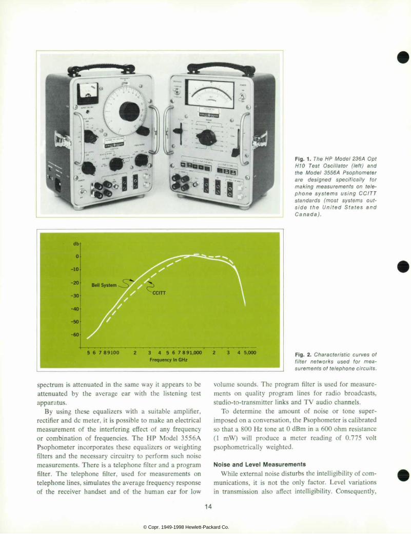
F ig . 1 . The HP Mode l 236 A Op t H 1 0 T e s t O s c i l l a t o r ( l e f t ) a n d t h e M o d e l 3 5 5 6 / 4 P s o p h o m e t e r a r e d e s i g n e d s p e c i f i c a l l y t o r m a k i n g m e a s u r e m e n t s o n t e l e p h o n e s y s t e m s u s i n g C C I T T s t a n d a r d s ( m o s t s y s t e m s o u t s i d e t h e U n i t e d S t a t e s a n d C a n a d a ) .
3 4 5 6 7 8 9 1 , 0 0 0 Frequency In GHz
F i g . 2 . C h a r a c t e r i s t i c c u r v e s o f f i l t e r n e t w o r k s u s e d f o r m e a su rements o f te lephone c i r cu i t s .
spectrum is attenuated in the same way it appears to be attenuated by the average ear with the listening test apparatus.
By using these equalizers with a suitable amplifier, rectifier and dc meter, it is possible to make an electrical measurement of the interfering effect of any frequency or combination of frequencies. The HP Model 355 6A Psophometer incorporates these equalizers or weighting filters and the necessary circuitry to perform such noise measurements. There is a telephone filter and a program filter. The telephone filter, used for measurements on telephone lines, simulates the average frequency response of the receiver handset and of the human ear for low
volume sounds. The program filter is used for measure ments on quality program lines for radio broadcasts, studio-to-transmitter links and TV audio channels.
To determine the amount of noise or tone super imposed on a conversation, the Psophometer is calibrated so that a 800 Hz tone at 0 dBm in a 600 ohm resistance (1 mW) will produce a meter reading of 0.775 volt psophometrically weighted.
Noise and Level Measurements While external noise disturbs the intelligibility of com
munications, it is not the only factor. Level variations in transmission also affect intelligibility. Consequently,
14
© Copr. 1949-1998 Hewlett-Packard Co.
assuring high quality transmission also requires level measurements. The HP Model 3556A Psophometer makes both noise and level measurements.
For noise measurements, the HP Model 3556A is a sensitive and accurate voltmeter/powermeter. In addi tion to the two CCITT noise weighting filters there are two low pass filters; 3 kHz and 15 kHz bandwidth may be selected for measuring noise on telephone lines and broadcast channels.
The four filters are built into the instrument and selected by a lever switch, eliminating the need for plug-in filters.
Pushbuttons set up circuits to measure either metallic noise (symmetrical noise voltage or normal mode noise voltage) and noise to ground (asymmetrical noise voltage or common mode noise voltage).
Unlike conventional rms-responding thermocouple meters, the Model 3556A has a fast response to input changes (200 ms response to impulse noise) to simulate the response of the human ear. if noise fluctuations make reading difficult, the reading can be smoothed by slow ing response time to 500 ms with a front panel switch.
For level measurements, the HP Model 3556A is a broadband voltmeter/powermeter. The frequency range covered is 30 Hz to 3 MHz at 75 n impedance for car rier level measurements. Bandwidths of 1 kHz to 150 kHz at 600 n and 1 kHz to 600 kHz at 150 n are offered. Flat response from 20 Hz to 20 kHz is also available at 600 n for audio frequency measurements.
To complement the Model 3556A for level measure ments (attenuations, gain and crosstalk levels), the HP 236A-H10 Telephone Test Oscillator is a reference source with the same flexibility.
HP 3556A Psophometer The Model 3556A consists basically of an input im
pedance selection network, a range attenuator tied to a balanced input transformer and input amplifier, select able weighting filters and an rms detector. Standard Siemens input-output connectors are on the front panel as well as banana type binding posts. The 75 n symmetri cal input is of BNC type.
The input impedance network provides the proper impedance across the input terminals to terminate or bridge the circuit under test. Inputs are terminated or non-terminated for 150 and 600 ohm symmetrical, and for 75 ohm asymmetrical. Non-terminated impedance is greater than 15 kn symmetrical and 100 kQ asymmetri cal, assuring that the instrument will not disturb working telephone circuits.
A symmetrical transformer is used in the input to achieve the required frequency response and balance between each input terminal and ground. As common mode voltages on a telephone line are sometimes high in noise-to-ground measurements, a circuit is switched into the input to provide 40 dB attenuation. In this case, the side of the line being measured is loaded with 100 kn, a load that is negligible in these circumstances.
In the hold mode a built-in holding coil simulates an off-hook condition and permits holding the line while noise or level measurements are being made.
The meter always reads dBm directly for 600 Q and 150 Q impedances. The meter also reads in volts for 600 n and 75 n impedances. Outputs for handsets and a dc recorder are also included.
The instrument weighs 6,8 kg, and is housed in a splashproof case for use in the field as well as in the office. It can be operated from mains power between 90 V and 250 V ac, 48 Hz to 440 Hz without voltage switching, or from rechargeable batteries (a dry battery is an option).
HP 236A-H10 Test Osci l la tor The Model 236A-H10 Telephone Test Oscillator con
sists of an oscillator-amplifier, attenuator, power supply, meter circuit and a selective output circuit. The oscillator uses a modified Wien bridge network to generate a stable, low-distortion, sine-wave signal. A peak detector replaces the classic light bulb, providing a degenerative feedback voltage to the oscillator circuit to stabilize the output am plitude.
A three-step precision attenuator is calibrated to supply + 10 to —30 dBm in 0.1 dBm steps into the selected out put impedances. The output is coupled through trans formers to provide a high degree of balance between each output terminal to ground. The 600 ohm output is coupled through a low frequency transformer (50 Hz to 20 kHz) and the 150 ohm and 75 ohm output through a high- frequency transformer (5 kHz to 560 kHz).
The reason for providing two output frequency ranges is because of different frequency range applications for the associated output impedances. The use of two trans formers provides much flatter frequency response than one wideband transformer.
The instrument weighs 6,1 kg and is housed in the same splashproof case as the Psophometer. It can be operated from mains power 1 15 or 230 volts ac, or from dry batteries.
Acknowledgments The advice and assistance of Pendell Pittman, Jim
Plumb and Don Wick are gratefully acknowledged. C
15
© Copr. 1949-1998 Hewlett-Packard Co.
S P E C I F I C A T I O N S H P M o d e l 3 5 5 6 A
Psophometer V O I C E F R E Q U E N C Y L E V E L M E A S U R E M E N T S ( F l a t I n p u t < 2 0 k H z ( u n c
t ions) V O L T A G E R A N G E : 0 . 1 m V t o 3 0 V f u l l s c a l e , 1 2 r a n g e s , I n a 1 , 3 , 1 0
s e q u e n c e . d B m R A N G E : - 7 8 d B m t o + 3 2 d B m f u l l s c a l e , 1 2 r a n g e s . F R E Q U E N C Y R A N G E : 2 0 H z t o 2 0 k H z . L E V E L A C C U R A C Y
1 0 0 H z t o 5 k H z : Â ± 0 . 2 d B 2 0 H z t o 2 0 k H z : Â ± 0 . 5 d B .
N O I S E M E A S U R E M E N T S ( F i l t e r e d i n p u t < 2 0 k H z f u n c t i o n s ) V O L T A G E R A N G E : 0 . 1 m V t o 3 0 V f u l l s c a l e , 1 2 r a n g e s , Â ¡ n a 1 , 3 , 1 0
s e q u e n c e . d B m R A N G E : - 7 8 d B m t o + 3 2 d B m f u l l s c a l e , 1 2 r a n g e s . W E I G H T I N G F I L T E R S : T E L E P H O N E a n d P R O G R A M w e i g h t i n g c u r v e s m e e t j o i n t r e q u i r e
m e n t s o f C C I T T P s o p h o m e t r i c R e c o m m e n d a t i o n P 5 3 . 3 k H z L O W - P A S S F I L T E R 1 5 k H z L O W - P A S S F I L T E R .
C A R R I E R F R E Q U E N C Y L E V E L M E A S U R E M E N T S ( F l a t i n p u t > 1 k H z funct ions)
V O L T A G E R A N G E : 3 m V t o 3 V f u l l s c a l e , 7 r a n g e s , Â ¡ n a 1 , 3 , 1 0 s e q u e n c e .
d B m R A N G E : - 4 8 d B m t o + 1 2 d B m f u l l s c a l e , 7 r a n g e s . F R E Q U E N C Y R A N G E : 3 0 H z t o 3 M H z . L E V E L A C C U R A C Y
6 0 0 n s y m m e t r i c a l 1 k H z t o 1 5 0 k H z : Â ± 0 . 5 d B 1 0 k H z t o 1 0 0 k H z : Â ± 0 . 2 d B .
1 5 0 S Ã s y m m e t r i c a l 1 k H z t o 6 0 0 k H z : Â ± 0 . 5 d B 1 0 k H z t o 3 0 0 k H z : Â ± 0 . 2 d B .
7 5 Ã 1 a s y m m e t r i c a l 1 0 0 H z t o 6 0 0 k H z : Â ± 0 . 2 d B 3 0 H z t o 1 M H z : Â ± 0 . 5 d B 1 M H z t o 3 M H z : Â ± 0 . 5 d B Â ± 1 0 % o f m e t e r r e a d i n g .
G E N E R A L M E T E R R E A D I N G : L i n e a r d B m s c a l e w i t h 1 2 d B m r a n g e a n d l o g
a r i t h m i c v o l t a g e s c a l e s w i t h 1 , 3 , 1 0 s e q u e n c e , i n d i c a t e r m s v a l u e o f i n p u t s i g n a l . d B m s c a l e i s v a l i d o n 6 0 0 Q a n d 1 5 0 O i m p e d a n c e s , v o l t a g e s c a l e s a r e v a l i d o n 6 0 0 à œ a n d 7 5 f i i m p e d a n c e s .
M E T E R R E S P O N S E 2 0 0 m s : R e s p o n s e t i m e t o I n d i c a t e a r e a d i n g f r o m - 1 0 d B m t o
0 d B m . 5 0 0 m s : R e s p o n s e t i m e t o I n d i c a t e a r e a d i n g f r o m - 1 0 d B m t o
0 d B m . M A X I N P U T V O L T A G E
a t o b : 1 5 0 V p e a k a o r b t o g r o u n d : 5 0 0 V p e a k .
P O W E R R E Q U I R E M E N T S H P M o d e l 3 5 5 6 A S t a n d a r d : 4 r e c h a r g e a b l e b a t t e r i e s ( 2 5 V t o t a l )
o r p o w e r l i n e f r o m 9 0 V a c t o 2 5 0 V a c ( w i t h o u t s w i t c h ) , 4 8 H z t o 4 4 0 H z , < 1 0 V A d u r i n g b a t t e r y c h a r g e .
H P 3 5 5 6 A O p t i o n 0 0 1 I n t e r n a l b a t t e r y : S i n g l e N E D A 2 0 2 4 5 V ' B ' b a t t e r y f u r n i s h e d .
A n y b a t t e r y m e e t i n g N E D A 2 0 2 - s p e c i f i c a t i o n s s u c h a s E V E - R E A D Y 4 8 2 o r B U R G E S S M 3 0 m a y b e u s e d .
B a t t e r y l i f e : 1 8 0 h r s @ 4 h r s p e r d a y . E x t e r n a l b a t t e r y : - 2 4 V t o - 4 8 V o f f i c e b a t t e r y , < 1 5 m A .
A C : 1 1 5 o r 2 3 0 V ( s w i t c h ) , 4 8 H z t o 4 4 0 H z , < 1 0 V A . D I M E N S I O N S : 1 9 7 m m w i d e , 2 9 9 m m h i g h , 2 0 7 m m d e e p ( 7 % I n x
1 1 % i n x 8 V e I n ) . W E I G H T : N e t 6 , 8 k g ( 1 5 I b ) , s h i p p i n g 7 , 5 k g ( 1 7 I b ) . P R I C E : H P 3 5 5 6 A ( a c l i n e a n d r e c h a r g e a b l e b a t t e r y ) $ 8 0 0 . 0 0 . H P
3 5 5 6 A s u p p l y ) 0 0 1 ( a c l i n e i n t e r n a l d r y b a t t e r y a n d e x t e r n a l s u p p l y ) $ 7 7 5 . 0 0 . ( O p e r a t i n g i n s t r u c t i o n s p r i n t e d i n t h e p r o t e c t i v e c o v e r i n E n g l i s h s u p p l i e d . A l s o a v a i l a b l e a t n o c h a r g e i n G e r m a n , O p t . 0 0 2 ; I t a l i a n , O p t . 0 0 3 ; F r e n c h , O p t . 0 0 4 ; S p a n i s h , O p t . 0 0 5 ; P o r t u g u e s e , O p t . 0 0 6 ; D u t c h , O p t . 0 0 7 ; a n d F i n n i s h , O p t . 0 0 8 . )
M O D E L 2 3 6 A O P T H 1 0 T E L E P H O N E T E S T O S C I L L A T O R T h e H P 2 3 6 A O p t . H 1 0 T e l e p h o n e T e s t O s c i l l a t o r u s e d i n c o n j u n c t i o n
w i t h t h e 3 5 5 6 A P s o p h o m e t e r m a k e s a c o m p l e t e t r a n s m i s s i o n t e s t s e t f o r a c c u r a t e , c o n v e n i e n t v o i c e a n d c a r r i e r m e a s u r e m e n t s . T h e 2 3 6 A O p t . H 1 0 s u p p l i e s p r e c i s e t e s t t o n e s f r o m - 3 1 d B m t o + 1 0 d B m i n 0 . 1 d B m s t e p s o v e r a f r e q u e n c y r a n g e o f 5 0 H z t o 5 6 0 k H z . T h e t e s t o s c i l l a t o r i n c o r p o r a t e s t h e s a m e r u g g e d , p o r t a b l e d e s i g n , o u t p u t j a c k f l e x i b i l i t y a n d d i a l - t h r o u g h a n d h o l d f e a t u r e s a s t h e 3 5 5 6 A . O u t p u t i s f u l l y s y m m e t r i c a l a n d f l o a t i n g w i t h a c h o i c e o f 1 5 0 0 o r 6 0 0 S ! s e l e c t a b l e o u t p u t i m p e d a n c e . A n o u t p u t I m p e d a n c e o f 7 5 ' . . ' a s y m m e t r i c a l i s a l s o s u p p l i e d .
P R I C E : H P 2 3 6 A O p t . H 1 0 , $ 6 5 0 . 0 0 . ( O p e r a t i n g i n s t r u c t i o n s p r i n t e d i n t h e p r o t e c t i v e c o v e r I n E n g l i s h
s u p p l i e d . A l s o a v a i l a b l e a t n o c h a r g e i n G e r m a n , O p t . 0 0 2 ; I t a l i a n , O p t . 0 0 3 ; F r e n c h , O p t . 0 0 4 ; a n d S p a n i s h , O p t . 0 0 5 . )
M A N U F A C T U R I N G D I V I S I O N : L O V E L A N D D I V I S I O N L O V E L A N D , C O L O R A D O 8 0 5 3 7
Jim Plumb E H | H I B J i m e a r n e d h i s B S E E d e g r e e ,
â € ” â € ¢ " x I w i t h h o n o r s , f r o m t h e F l o r i d a I I n s t i t u t e o f T e c h n o l o g y . A f t e r
â € ¢ t f f Q T * * ' I g r a d u a t i o n h e j o i n e d t h e H P * L o v e l a n d D i v i s i o n a s c u s t o m e r
se rv i ce eng inee r , and la te r was an app l i ca t i ons eng inee r . He was p ro jec t l eade r on the 3 5 5 6 A p r o j e c t . P r e s e n t l y J i m s u p e r v i s e s H P L o v e l a n d ' s s p e c i a l h a n d l i n g d e p a r t m e n t .
J im en joys a va r ie ty o f o u t d o o r h o b b i e s , i n c l u d i n g h i k i ng and c l imb ing i n t he l oca l
moun ta ins , as we l l as sk i i ng and mo to rcyc l i ng .
Jacques Hol tz inger J a c q u e s i s a n a t i v e o f
^ â € ” - ~ J , V e r s a i l l e s , F r a n c e . H e j o i n e d ^ A f i k t h e H e w l e t t - P a c k a r d f i e l d
engineer ing of f ice in Par is ¡n r * * ' 1 9 6 4 a s a s u p p o r t e n g i n e e r . H e
became a f i e ld eng ineer in 1966, then came to the Love land , Co 'o rado D iv i s i on i n 1969, where he was a member o f the des ign team on the Mode l 3556A. He i s p resen t l y p r o d u c t m a n a g e r o n t h e Mode l 3556A.
L i v i n g i n C o l o r a d o e s p e c i a l l y appea l s t o Jacques , w i t h sk i i ng , f i sh i ng and ho rseback r id ing rank ing h igh among h is favo r i te ac t i v i t i es .
HEWLETT-PACKARD JOURNAL o DECEMBER 1970 volume 22 • Number 4 T E C H N I C A L U . S . A . F R O M T H E L A B O R A T O R I E S O F H E W L E T T - P A C K A R D C O M P A N Y 1 5 0 1 P A G E M I L L R O A D , P A L O A L T O , C A L I F O R N I A 9 4 3 0 4 U . S . A .
Hew le t t -Packard S .A . 1217 Meyr in -Geneva , Sw i t ze r land • Yokagawa-Hewle t t -Packard L td . , Sh ibuya-Ku , Tokyo 151 Japan
Editor: R. Jordan Snyder Editor ia l Board R. P. Dolan. u. D Shergal is Art Director: Arvid A. Danielson Assistant: Maridel Jordan
© Copr. 1949-1998 Hewlett-Packard Co.


![Lossless compression of digital audio - HP LabsLossless compression of digital audio - HP Labs ... y > ] > ...](https://static.fdocuments.us/doc/165x107/5e8ec5c8b729fb6de750814f/lossless-compression-of-digital-audio-hp-labs-lossless-compression-of-digital.jpg)


