PERTRONIX DIGITAL HP - Digital HP - Digital HP Ignition Box Digital HP is a high power CD ignition...
29
Transcript of PERTRONIX DIGITAL HP - Digital HP - Digital HP Ignition Box Digital HP is a high power CD ignition...


PERTRONIX DIGITAL HP INSTALLATION INSTRUCTIONS
Specifications ................................................................. 4General Information ........................................................ 5Coil Compatibility............................................................ 6Mounting the Digital HP.................................................. 7Wiring ............................................................................. 8User Interface ............................................................... 12Programming ................................................................ 13 Cylinder Selection ..................................................... 15 Trigger, Multispark, Power Selection ......................... 16 Rev Limiter Verification .............................................. 17 Rev Limiters .........................................................18-19 Start Retard............................................................... 20 Shift Light / RPM Switch ........................................... 21 Tachometer Calibration ............................................. 22Wiring Diagrams ......................................................23-27Diagnostics / Error Detection........................................ 28Warranty Policy ............................................................ 29
TABLE OF CONTENTS

SPECIFICATIONSOperating Voltage: 9-22 Volts
Cranking Voltage: 8-22 Volts
Current Draw: 1.2A per 1000 RPM
Input Triggers: Points, Electronic Ignition, or Mag Pickup
Output Voltage: 530 Volts
Output Energy: Up to 187+mJ primary spark
Tach Output Signal: 12 Volt square wave, 50% duty cycle
Multi-Spark Window: Up to 20 crank degrees
Start Retard: Adjustable 0-18 degrees / 500-1400 RPM
Weight: 0.7 lb
Length 5.15 Inches
Width 3.75 Inches
Height 1.65 Inches
Mounting Bolt Pattern 3.5” X 3.25”
PARTS INCLUDED1 - Digital HP Ignition1 - Main Harness
1 - Mag Trigger Harness1 - Hardware Pack
TOOLS NEEDED FOR INSTALLATION• Phillips Screw Driver• Wrenches and Sockets• Wire Cutters / Stripers
• Power Drill & #20 Drill Bit• Crimper
(PerTronix T3001 Recommended)
4

GENERAL INFORMATION
• It is important to read the entire installation manual before starting your installation. Doing so will insure proper setup and trouble free operation.
• Only connect the Digital HP main battery power leads to the battery. If installing on a vehicle with a trunk mounted battery, extend the Digital HP battery leads with 10 - 8 AWG wire.
• Completely disconnect and remove the Digital HP before performing any welding on the vehicle.
• Optional: Programming can be done on the bench top if desired. See page 13 for details
• If using the gray wires to trigger a fuel injection system, make sure to disable the rev limiter verification setting found on page 17.
• Remember to disconnect the battery negative cable before installation• The Digital HP should only be used in conjunction with a low resistance
coil. We recommend the Flame-Thrower III canister coil or Flame-Thrower HP E-core coil for optimal performance.
• Never use solid core spark plug wires with this Ignition system. • We recommend the factory spark plug heat range be used. The spark
plug gap can be incrementally increased by 0.005” while testing after changes for best performance. Note extending the plug gap can shorten the spark plug life and increase service intervals of the cap and rotor.
• Resistor style rotors are not recommended• Completely disconnect and remove the Digital HP before performing
any welding on the vehicle.• This system is Legal only for Closed Course Competition Vehicles
5 PerTronix Technical Support (909) 547-9058 www.pertronix.com

UNDERSTANDING CAPACITIVE DISCHARGE
Inductive systems require a longer time, or dwell period, for the coil to charge fully. The Digital HP CD ignition steps up the primary voltage to 530+ volts and stores this in a capacitor, which when triggered, quickly dumps the high voltage into the coil. The coil then reaches maximum charge much quicker.
Most CD boxes stop multisparking around 3000 RPM. This is due to the rate at which other CD ignitions can multispark, about 1 time per millisecond. At 3000 RPM, their second spark occurs about 20 crank degrees later. The Digital HP sparks 50% faster. This mean that you have 2-3 times as many sparks at 3000 rpm and multiple sparks to 7000 + RPM. More importantly, the following sparks are closer to the de-sired ignition timing for better combustion
The Digital HP is a high power CD ignition systems and needs a coil that is capable of handling the increased power without overheating. For normal street driving, the Digital HP will work with most coils that have a primary resistance of 3 ohms or less. A low resistance coil such as the Flame-Thrower III canister coil, or Flame-Thrower HC or HP are highly recommended. For extended high RPM use, such as circle track or road racing, only use the Flame-Thrower HP coil ( PN 60100) or equivalent. The Flame-Thrower HP coil is an ultra low resistance coil designed specifically for CD ignitions.
COIL COMPATIBILITY
Application Canister Coils E-Core Style Coils
Street Driving or Drag Strip Flame-Thrower III PN 44001, 44011
Flame-Thrower HC/HP PN 60103, 60100
Road Racing/Circle Track NOT RECOMMENDED Flame-Thrower HP PN 60100
6
MOUNTING THE DIGITAL HP
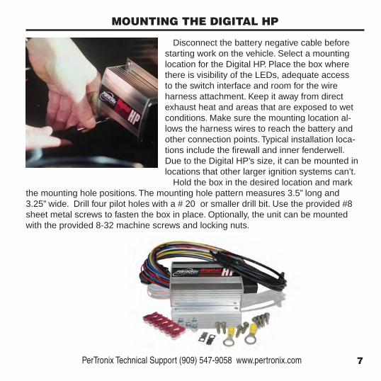
Disconnect the battery negative cable before starting work on the vehicle. Select a mounting location for the Digital HP. Place the box where there is visibility of the LEDs, adequate access to the switch interface and room for the wire harness attachment. Keep it away from direct exhaust heat and areas that are exposed to wet conditions. Make sure the mounting location al-lows the harness wires to reach the battery and other connection points. Typical installation loca-tions include the firewall and inner fenderwell. Due to the Digital HP’s size, it can be mounted in locations that other larger ignition systems can’t.
Hold the box in the desired location and mark the mounting hole positions. The mounting hole pattern measures 3.5” long and 3.25” wide. Drill four pilot holes with a # 20 or smaller drill bit. Use the provided #8 sheet metal screws to fasten the box in place. Optionally, the unit can be mounted with the provided 8-32 machine screws and locking nuts.
7 PerTronix Technical Support (909) 547-9058 www.pertronix.com

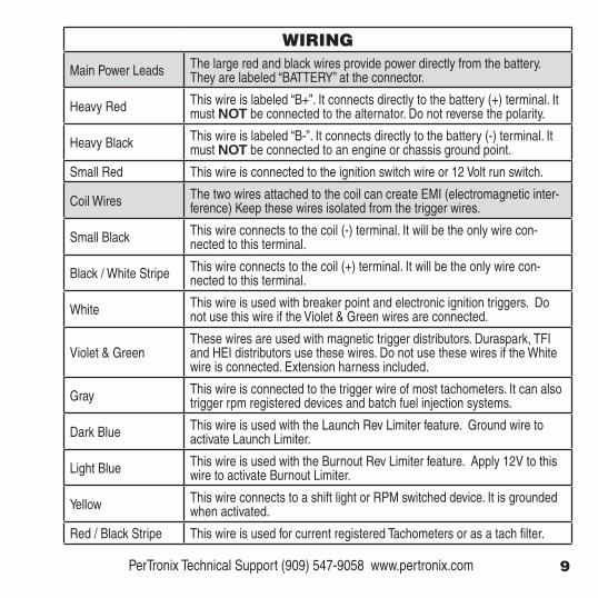
GRAY - TACHOMETER
VIOLET - MAG TRIGGER DIST.
HEAVY RED - BATTERYHEAVY BLACK - BATTERY
RED - IGNITION SWITCH
DARK BLUE - LAUNCH SWITCHLIGHT BLUE - BURNOUT SWITCH
WHITE - DISTRIBUTOR
YELLOW - SHIFT LIGHT
GREEN - MAG TRIGGER DIST.
BLACK - COIL
RED / BLACK - SPECIAL USE
BLACK / WHITE STRIPE - COIL
WIRING
The Digital HP uses a locking automotive connector. Push the wiring harness connector onto the box until it clicks. Push in the red lock to insure the connector is secure. To remove the connector, pull the red lock out, and press down on black latch while pulling on the connector.
Route the wires towards their ultimate connection points. Make sure to keep the wires away from sharp edges, moving objects, and heat sources.
Determine the appropriate length for each wire then cut the wire to length. Any unused wires should be coiled and taped out of the way. The most common terminals are provided to complete each connection. Use a proper crimp tool to attach the ter-minals to the wires. The PerTronix T3001 quick change crimp tool provides excellent crimp connections . It is best to keep the coil wires (Black & Black/White) separated from the trigger wires (White & Violet, Green) to prevent EMI. Only connect the Digi-tal HP main battery power leads directly to the battery. If necessary, the wires can be extend with 10 - 8 AWG wire.
Expanded wiring diagrams for various application can be found on pages 23-27 of this manual.
8
WIRING
Main Power Leads The large red and black wires provide power directly from the battery. They are labeled “BATTERY” at the connector.
Heavy Red This wire is labeled “B+”. It connects directly to the battery (+) terminal. It must NOT be connected to the alternator. Do not reverse the polarity.
Heavy Black This wire is labeled “B-”. It connects directly to the battery (-) terminal. It must NOT be connected to an engine or chassis ground point.
Small Red This wire is connected to the ignition switch wire or 12 Volt run switch.
Coil Wires The two wires attached to the coil can create EMI (electromagnetic inter-ference) Keep these wires isolated from the trigger wires.
Small Black This wire connects to the coil (-) terminal. It will be the only wire con-nected to this terminal.
Black / White Stripe This wire connects to the coil (+) terminal. It will be the only wire con-nected to this terminal.
White This wire is used with breaker point and electronic ignition triggers. Do not use this wire if the Violet & Green wires are connected.
Violet & GreenThese wires are used with magnetic trigger distributors. Duraspark, TFI and HEI distributors use these wires. Do not use these wires if the White wire is connected. Extension harness included.
Gray This wire is connected to the trigger wire of most tachometers. It can also trigger rpm registered devices and batch fuel injection systems.
Dark Blue This wire is used with the Launch Rev Limiter feature. Ground wire to activate Launch Limiter.
Light Blue This wire is used with the Burnout Rev Limiter feature. Apply 12V to this wire to activate Burnout Limiter.
Yellow This wire connects to a shift light or RPM switched device. It is grounded when activated.
Red / Black Stripe This wire is used for current registered Tachometers or as a tach filter.
9 PerTronix Technical Support (909) 547-9058 www.pertronix.com
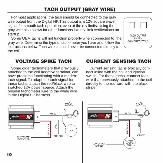
For most applications, the tach should be connected to the gray wire output from the Digital HP. This output is a 12V square wave signal for smooth tach operation, even at the rev limits. Using the gray wire also allows for other functions like rev limit verifications on startup.
Some OEM tachs will not function properly when connected to the gray wire. Determine the type of tachometer you have and follow the instructions below. Tach wires should never be connected directly to the coil.
TACH OUTPUT (GRAY WIRE)
GRAY
12V IGNITION SWITCH
WHITE
RED /
BLAC
K
NOT USED
CURRENTSENSING
TACH
TACH OUTPUT0 - 12 V
50% DUTY CYCLE
Current sensing tachs typically con-nect inline with the coil and ignition switch. For these tachs, connect tach wire that previously attached to the coil directly to the red wire with the black stripe.
CURRENT SENSING TACHGR
AY
12V SWITCHED FROM IGNITION
WHITE
RED /
BLAC
K
NOT USED
TACH
Some older tachometers that previously attached to the coil negative terminal, can have problems functioning with a modern tach signal. To adapt the tach signal for these tachs, attach the red/black wire to switched 12V power source. Attach the original tachometer wire to the white wire in the Digital HP harness.
VOLTAGE SPIKE TACH
10
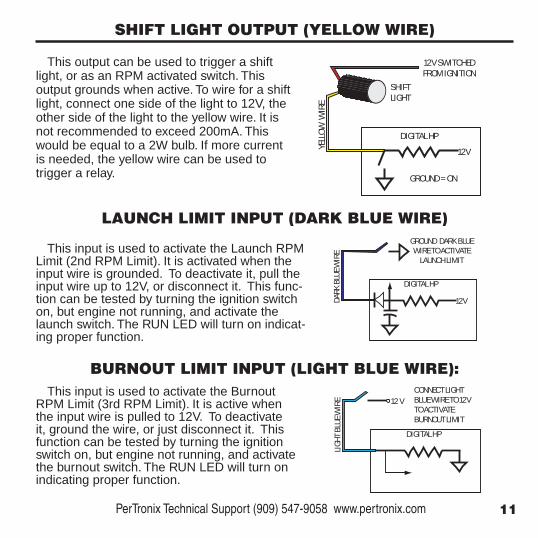
SHIFT LIGHT OUTPUT (YELLOW WIRE)
This output can be used to trigger a shift light, or as an RPM activated switch. This output grounds when active. To wire for a shift light, connect one side of the light to 12V, the other side of the light to the yellow wire. It is not recommended to exceed 200mA. This would be equal to a 2W bulb. If more current is needed, the yellow wire can be used to trigger a relay.
This input is used to activate the Launch RPM Limit (2nd RPM Limit). It is activated when the input wire is grounded. To deactivate it, pull the input wire up to 12V, or disconnect it. This func-tion can be tested by turning the ignition switch on, but engine not running, and activate the launch switch. The RUN LED will turn on indicat-ing proper function.
This input is used to activate the Burnout RPM Limit (3rd RPM Limit). It is active when the input wire is pulled to 12V. To deactivate it, ground the wire, or just disconnect it. This function can be tested by turning the ignition switch on, but engine not running, and activate the burnout switch. The RUN LED will turn on indicating proper function.
LAUNCH LIMIT INPUT (DARK BLUE WIRE)
BURNOUT LIMIT INPUT (LIGHT BLUE WIRE):
DARK
BLUE
WIR
E
DIGITAL HP
12V
GROUND DARK BLUE WIRE TO ACTIVATE
LAUNCH LIMIT
SHIFTLIGHT
YELLO
W W
IRE
DIGITAL HP12V
12V SWITCHEDFROM IGNITION
GROUND = ON
LIGHT
BLUE
WIR
E
DIGITAL HP
12 VCONNECT LIGHT BLUE WIRE TO 12V TO ACTIVATE BURNOUT LIMIT
11 PerTronix Technical Support (909) 547-9058 www.pertronix.com

USER INTERFACE
RUN
PWR
CYL MODE 1000 100RPM
PWR LED Red LED comes on with the key, and is used to indicate diagnostic codes.
RUN LED Green LED comes on while running, and is used to indicate program activity and diagnostic codes.
CYL Switch Used to select the number of cylinders.
MODE Switch Used to activate various programming features.
1000 Switch Used to set 1000 RPM increments for rev limiters and to select options while in some program modes.
100 Switch Used to set 100 RPM increments for rev limiters and to select options while in some program modes.
12

PROGRAMMING
Setting Default Value Cylinders No default value. Must be set by user.Trigger Type Breaker points or Electronic Ignition (Rising Edge)Fatal Rev Limit 5500 RPMLaunch Rev Limit 4000 RPMBurnout Rev Limit 3000 RPMShift Light On 5000 RPMShift Light Off 8500 RPMMulti-Spark On Power Level 145mJ Start Retard Degrees 10 Crank Degrees Start Retard RPM 800 RPM
The following settings are loaded into the Digital HP from the factory. Once the set-tings are changed by the user, the new settings overwrite the default values, and are stored into memory.
Optional: Programming of the Digital HP can be done before installing. This requires a 9V battery. Attach the small black wire to the battery negative terminal. Program your settings. When finished hold the small red wire on the battery positive terminal. The LEDs will blink indicating the setting is saved.
SMALL BLACK
SMALL RED
BENCH TOP PROGRAMMING
13 PerTronix Technical Support (909) 547-9058 www.pertronix.com
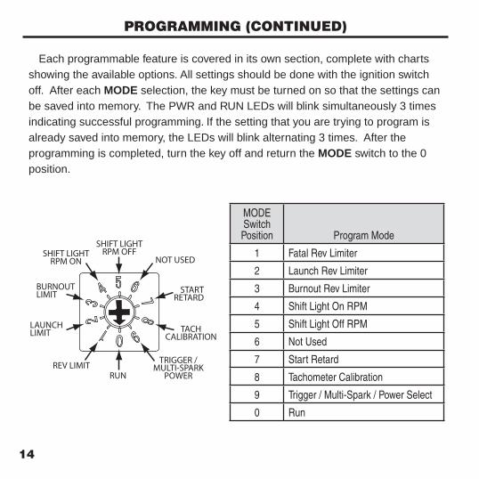
Each programmable feature is covered in its own section, complete with charts showing the available options. All settings should be done with the ignition switch off. After each MODE selection, the key must be turned on so that the settings can be saved into memory. The PWR and RUN LEDs will blink simultaneously 3 times indicating successful programming. If the setting that you are trying to program is already saved into memory, the LEDs will blink alternating 3 times. After the programming is completed, turn the key off and return the MODE switch to the 0 position.
PROGRAMMING (CONTINUED)
SHIFT LIGHTRPM OFF
NOT USED
STARTRETARD
REV LIMITRUN
TACHCALIBRATION
TRIGGER / MULTI-SPARK
POWER
LAUNCHLIMIT
BURNOUTLIMIT
SHIFT LIGHTRPM ON
MODE Switch Position Program Mode
1 Fatal Rev Limiter
2 Launch Rev Limiter
3 Burnout Rev Limiter
4 Shift Light On RPM
5 Shift Light Off RPM
6 Not Used
7 Start Retard
8 Tachometer Calibration
9 Trigger / Multi-Spark / Power Select
0 Run
14

CYLINDER SELECTION
The switch labeled “CYL” is for selecting the number of cylinders. The Digital HP will work on applications ranging from a single cylinder to 12 cylinder engine. Refer-ence the chart and diagram below to determine the appropriate switch position for your application. Turn the dial so that the arrow points to your selection. This selection must remain fixed in this position for proper operation and RPM calculations. The cylinder selection setting does not require that the key be cycled to save the setting into memory.
5 CYL6 CYLEVEN FIRE
6 CYLODD FIRE
8 CYL
12 CYL
4 CYL
3 CYL
2 CYL
1 CYL10 CYL
CYL Switch Position
Cylinders
1 Single cylinder engine
2 Two cylinder odd or even fire engines
3 Three cylinder engines
4 Four cylinder engines
5 Five cylinder engines
6 Six cylinder even fire engines
7 Six cylinder odd fire engines
8 8 cylinder engines
9 12 cylinder engines
0 10 cylinder engines
15 PerTronix Technical Support (909) 547-9058 www.pertronix.com

TRIGGER / MULTI-SPARK / POWER SELECTION
The trigger type, multiple spark and power settings are all three set at the same time. Within this program mode, the Rev Limit Verification setting is also established (pg 17).
The trigger type can be configured for traditional breaker point triggers, electronic ignition triggers (rising edge) or magnetic trig-gers (falling edge). The multiple spark function can be turned on or off and the power level adjusted between 145mJ and 187mJ.
Select your trigger type in the chart below. Next choose your desired settings for the multiple spark and power level functions. The “1000” switch position is indicated in the column to the right. Write this position down and proceed to the Rev Limit Verifi-cation section on the next page.
Trigger Type
Multi-Spark
Power Level
1000 Switch Position
Points / Electronic Ignition (Rising Edge) ON 187mJ 0Points / Electronic Ignition (Rising Edge) ON 145mJ 1
Points / Electronic Ignition (Rising Edge) OFF 187mJ 2Points / Electronic Ignition (Rising Edge) OFF 145mJ 3Magnetic Trigger (Falling Edge) ON 187mJ 4
Magnetic Trigger (Falling Edge) ON 145mJ 5Magnetic Trigger (Falling Edge) OFF 187mJ 6Magnetic Trigger (Falling Edge) OFF 145mJ 7Not Used Not Used Not Used 8Not Used Not Used Not Used 9
MO
DE
9
Note: All PerTronix Ignitor triggers should be set to Electronic Ignition (Rising Edge)
16
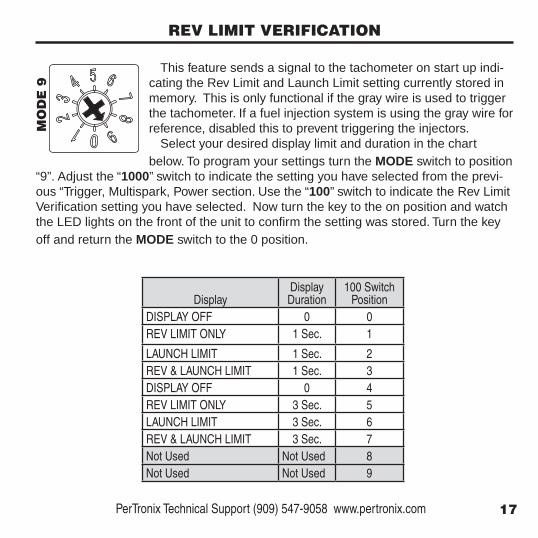
REV LIMIT VERIFICATION
This feature sends a signal to the tachometer on start up indi-cating the Rev Limit and Launch Limit setting currently stored in memory. This is only functional if the gray wire is used to trigger the tachometer. If a fuel injection system is using the gray wire for reference, disabled this to prevent triggering the injectors.
Select your desired display limit and duration in the chart below. To program your settings turn the MODE switch to position
“9”. Adjust the “1000” switch to indicate the setting you have selected from the previ-ous “Trigger, Multispark, Power section. Use the “100” switch to indicate the Rev Limit Verification setting you have selected. Now turn the key to the on position and watch the LED lights on the front of the unit to confirm the setting was stored. Turn the key off and return the MODE switch to the 0 position.
Display
Display Duration
100 Switch Position
DISPLAY OFF 0 0REV LIMIT ONLY 1 Sec. 1
LAUNCH LIMIT 1 Sec. 2REV & LAUNCH LIMIT 1 Sec. 3DISPLAY OFF 0 4REV LIMIT ONLY 3 Sec. 5LAUNCH LIMIT 3 Sec. 6REV & LAUNCH LIMIT 3 Sec. 7Not Used Not Used 8Not Used Not Used 9
MO
DE
9
17 PerTronix Technical Support (909) 547-9058 www.pertronix.com
FATAL REV LIMITER
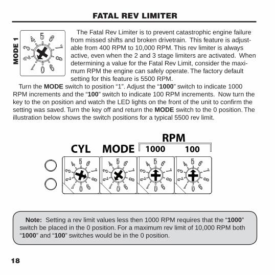
The Fatal Rev Limiter is to prevent catastrophic engine failure from missed shifts and broken drivetrain. This feature is adjust-able from 400 RPM to 10,000 RPM. This rev limiter is always active, even when the 2 and 3 stage limiters are activated. When determining a value for the Fatal Rev Limit, consider the maxi-mum RPM the engine can safely operate. The factory default setting for this feature is 5500 RPM.
Turn the MODE switch to position “1”. Adjust the “1000” switch to indicate 1000 RPM increments and the “100” switch to indicate 100 RPM increments. Now turn the key to the on position and watch the LED lights on the front of the unit to confirm the setting was saved. Turn the key off and return the MODE switch to the 0 position. The illustration below shows the switch positions for a typical 5500 rev limit.
Note: Setting a rev limit values less then 1000 RPM requires that the “1000” switch be placed in the 0 position. For a maximum rev limit of 10,000 RPM both “1000” and “100” switches would be in the 0 position.
RUN
PWR
CYL MODE 1000 100RPM
MO
DE
1
18
LAUNCH REV LIMITER
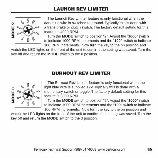
The Launch Rev Limiter feature is only functional when the dark blue wire is switched to ground. Typically this is done with a trans brake or clutch switch. The factory default setting for this feature is 4000 RPM.
Turn the MODE switch to position “2”. Adjust the “1000” switch to indicate 1000 RPM increments and the “100” switch to indicate 100 RPM increments. Now turn the key to the on position and
watch the LED lights on the front of the unit to confirm the setting was saved. Turn the key off and return the MODE switch to the 0 position.
BURNOUT REV LIMITER
The Burnout Rev Limiter feature is only functional when the light blue wire is supplied 12V. Typically this is done with a momentary switch or toggle. The factory default setting for this feature is 3000 RPM.
Turn the MODE switch to position “3”. Adjust the “1000” switch to indicate 1000 RPM increments and the “100” switch to indicate 100 RPM increments. Now turn the key to the on position and
watch the LED lights on the front of the unit to confirm the setting was saved. Turn the key off and return the MODE switch to the 0 position.
MO
DE
2M
OD
E 3
19 PerTronix Technical Support (909) 547-9058 www.pertronix.com

START RETARD SETTING
The Digital HP start retard feature controls the degrees of retard, and the RPM at which the retard feature shuts off. When this is enabled, the start up timing is retarded until the engine reaches the selected RPM. This helps high compression engines and applications with locked-out distributors start easier.
If you are using an Ignitor II or III trigger, or any other system that has a built in start retard, the Digital HP start retard feature
should be turned off. To adjust the start retard settings, turn the MODE switch to position 7. Use the
charts below to determine the degrees of retard and the start RPM that works best for your engine. The 1000 switch adjust the degrees of retard and the 100 switch ad-just the start RPM. When finished turn the key to the on position and watch the LED lights on the front of the unit to confirm the setting was saved. Turn the key off and return the MODE switch to the 0 position.
1000 Switch Position
StartDegrees
0 OFF1 2°
2 4°3 6°4 8°5 10°6 12°7 14°8 16°9 18°
100 Switch Position
StartRPM
0 5001 600
2 7003 8004 9005 10006 11007 12008 13009 1400
MO
DE
7
Note: Once the start RPM is reached, this feature goes to sleep and will not acti-vate again unless the engine RPM drops to 1/2 of the established start RPM
20

SHIFT LIGHT SETTINGThe shift light and RPM switch will only function when the yellow wire is used. To
set this feature up for a shift light, move the MODE switch to position 4. Now using the “1000” and “100” switches, select your desired shift light ON RPM. Turn the key on to save the setting, then turn the key back off. Move the MODE switch to position 5. Select a RPM equal to or just below your shift light ON setting. Turn the “1000” and “100” switch to program the shift light OFF RPM. Again turn the key on to save the setting and then turn the key back off. Remember to return the MODE switch to 0.
MO
DE
4 &
5
To program this feature as an RPM activated switch, turn the MODE switch to posi-tion 4. Using the “1000” and “100” switches, set the RPM in which the feature will be activated. Turn the key on to save the setting, then turn the key back off. Move the MODE switch to position 5. Now again using the “1000” and “100” switches, set the RPM in which the feature will turn off. Turn the key on to save the setting and then turn the key back off. Remember to return the MODE switch to 0.
RPM ACTIVATED SWITCH SETTING
The Digital HP shift light output can be used as a standard shift light, or as an RPM activated window switch. The difference in the two settings is that the shift light turns on above a certain RPM, and then shuts off when RPMs drop off again. A window switch turns on when the RPM is between the two RPM values, and shuts off when it is either above that range, or below it.
When set up as a shift light, error codes will be displayed on the shift light.
SHIFT LIGHT / RPM SWITCH
21 PerTronix Technical Support (909) 547-9058 www.pertronix.com

TACHOMETER CALIBRATION
The Digital HP tachometer calibration feature generates a high-ly accurate signal to the tachometer when its attached to the gray wire. There is no spark created, while the tach is sent a simu-lated steady RPM. This give the user visibility of their tachometer accuracy. If the tachometer has calibration adjustments, then the tach can be corrected. This feature should not be used if the gray wire triggers a fuel injection system.
To use this feature, turn the MODE switch to position 8. Adjust the “1000” and “100” switches to set the desired RPM. Turn the key on and observe the tachometer.
MO
DE
8
More information on wiring and troubleshooting tachometers can be found on pages 10
22
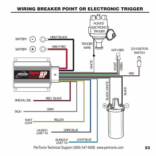
GRAY
YELLOWSHIFTLIGHT
TACH
HEAVY RED
HEAVY BLACK
BATTERY
BATTERY
RED
12V IGNITION SWITCH
LAUNCHLIMIT IN
DARK BLUE
BURNOUTLIMIT IN
LIGHT BLUE
WHI
TE
TRIGGERWIRE
VIOL
ET
GREE
N
POINTS/ELECTRONIC
TRIGGER
RED / BLACKSPECIAL USE
NOT USED
BLAC
K /W
HITE
BLAC
K
WIRING BREAKER POINT OR ELECTRONIC TRIGGER
23 PerTronix Technical Support (909) 547-9058 www.pertronix.com
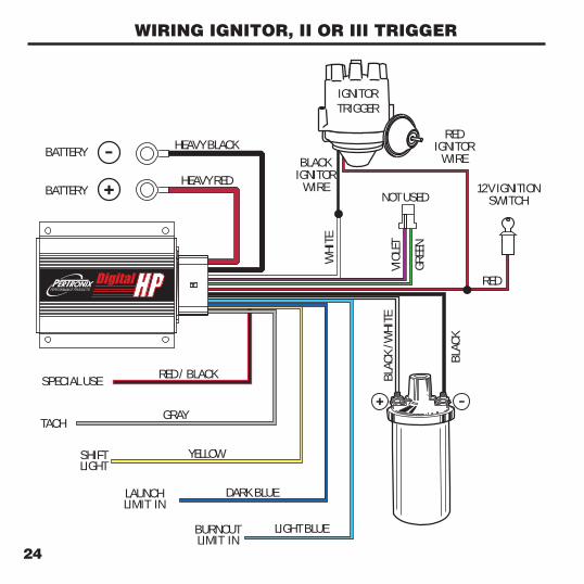
WIRING IGNITOR, II OR III TRIGGER
GRAY
YELLOWSHIFTLIGHT
TACH
HEAVY RED
HEAVY BLACK
BATTERY
BATTERY
RED
12V IGNITION SWITCH
LAUNCHLIMIT IN
DARK BLUE
BURNOUTLIMIT IN
LIGHT BLUE
WHI
TE
BLACKIGNITOR
WIRE
VIOL
ET
GREE
N
RED / BLACKSPECIAL USE
NOT USED
BLAC
K /W
HITE
BLAC
K
IGNITORTRIGGER
REDIGNITOR
WIRE
24

GRAY
YELLOWSHIFTLIGHT
TACH
HEAVY RED
HEAVY BLACK
BATTERY
BATTERY
RED
12V IGNITION SWITCH
LAUNCHLIMIT IN
DARK BLUE
BURNOUTLIMIT IN
LIGHT BLUE
WHI
TE
VIOL
ET
GREE
N
RED / BLACKSPECIAL USE
NOT USED
BLAC
K /W
HITE
BLAC
K
MAGNETICPICKUP
DISTRIBUTOR
WIRING MAGNETIC PICKUP DISTRIBUTOR
25 PerTronix Technical Support (909) 547-9058 www.pertronix.com

GRAY
YELLOWSHIFTLIGHT
TACH
HEAVY RED
HEAVY BLACK
BATTERY
BATTERY
RED
12V IGNITION SWITCH
LAUNCHLIMIT IN
DARK BLUE
BURNOUTLIMIT IN
LIGHT BLUE
WHI
TE
VIOL
ET
GREE
N
RED / BLACKSPECIAL USE
NOT USED
BLAC
K /W
HITE
BLAC
K
C-B+GND
TOGROUND
WIRING GM HEI DISTRIBUTOR
Do not use TACH terminal on HEI. Tach should connect to gray wire.
Remove module and condenser from distributor. Attached Violet and Green wires directly to the pickup coil wires.
Black / White Stripe wire connects to B+ terminal
Black wire connects to (C-) terminal
26

DIAGNOSTICSThe Digital HP performs on board diagnostics and error checking be-
fore each start and while the system is running. If any of these checks fail, it will attempt to disable certain features, such as multiple sparks, in an attempt to continue running. If the error is major, it may shut down completely.
Should an error occur, the system status will be displayed through the Red and Green LEDs on the front of the unit. This code is not stored in memory and will only be visible while the key remains in the on position. Between each read out there will be a 2 second pause, then it will repeat until the key is turned off. The Red LED will flash a series of long blinks for the 10s digit, followed by short blinks for the 1’s digit. If a major fault is detected both Red and Green LEDs will flash together. Momentary errors such as low start voltage will repeat 5 time and then disappear.
Error Code Fault Condition Possible Cause
11 Batt. Voltage Low < 8 V Weak battery, charging system or inadequate power or ground wiring
12 Batt. Voltage High > 25 V Battery or alternator voltage too high
13 Batt. Voltage Drop > 6.5V Drop Main battery red wire not connected directly to battery, or weak battery
14 Batt. Voltage Low (Starting) < 7 V Weak battery, or inadequate power or ground wiring
16 DC Power Supply < 5 V Weak battery, or inadequate power or ground wiring21 Coil Output Open Coil output wire not connected to coil, bad coil22 Coil Output Shorted Output wire not tied to ground or damaged unit 31 Switched 12V Low < 8.5 V Weak battery, charging system or inadequate power or ground wiring32 Switched 12V High > 24.0 V Battery or alternator voltage too high
33 Switched 12V Excessive Drop Weak battery, or voltage to Small Red wire insufficient.
34 Switched 12V Low (Starting)
< 8.0 V Weak battery, or Inadequate power, ground wiring
35 Switched 12V Low <7.0 V Weak battery, or Inadequate power, ground wiring
RUN
PWR
CYL MODE 1000 100RPM
28

PerTronix LLC. warrants to the original Purchaser of this product that the prod-uct shall be free from defects in material and workmanship for a period of 12 months from the date of purchase.
If within the period of the foregoing warranty PerTronix finds, after inspection, that the product or any component thereof is defective, PerTronix will, at its option, repair such product or component or replace them with an identical or similar product or component PROVIDED that within such period Purchaser:
1. Promptly notifies PerTronix, in writing, of such defects.2. Delivers the defective product or component to PerTronix (Attn: Warranty)
with proof of purchase date; and3. Has installed and used the product in a normal and proper manner, consis-
tent with 4. PerTronix printed instructions.
THE FOREGOING LIMITED WARRANTY IS EXCLUSIVE AND IN LIEU OF ALL OTHER WARRANTIES, WHETHER EXPRESSED OR IMPLIED, INCLUD-ING ANY IMPLIED WARRANTY OR MERCHANTABILITY OR FITNESS FOR A PARTICULAR PURPOSE.
THE FURNISHING OF A REPAIR OR REPLACEMENT COMPONENT OR COMPONENTS SHALL CONSTITUTE THE SOLE REMEDY OF PURCHAS-ER AND THE SOLE LIABILITY OF PerTronix WHETHER ON WARRANTY, CONTRACT OR FOR NEGLIGENCE, AND IN NO EVENT WILL PerTronix BE LIABLE FOR MONEY DAMAGES WHETHER DIRECT OR CONSEQUENTIAL.
LIMITED WARRANTY
29 PerTronix Technical Support (909) 547-9058 www.pertronix.com

NOTES:
30

0018-008813 REV 04/17
440 EAST ARROW HIGHWAY, SAN DIMAS CA, 91773

![[PPT]Ignition System Service - Higher Ed eBooks & Digital ... · Web viewIgnition System Service Chapter 38 Objectives Diagnose common ignition system problems Service ignition systems](https://static.fdocuments.us/doc/165x107/5ab3c1947f8b9aea528e9604/pptignition-system-service-higher-ed-ebooks-digital-viewignition-system.jpg)