189190 877429 Networking Catalog WEB - Balluffusa.balluff.com/OTPDF/02_IOLink_2011.pdf · IO-Link...
24
2.2 2 As the first standardized, uniform, universally applicable interface in control technology, IO-Link transmits all sensor and actuator signals to the controller. Likewise, IO-Link passes control data down to the lowest sensor level. All of this makes automation even more powerful than ever before. IO-Link advantages at a glance – Easy to get started, time-saving installation – Automatic adjustment during operation – Continuous monitoring
Transcript of 189190 877429 Networking Catalog WEB - Balluffusa.balluff.com/OTPDF/02_IOLink_2011.pdf · IO-Link...

IO-Link
2.22
As the first standardized, uniform, universally applicable
interface in control technology, IO-Link transmits all sensor
and actuator signals to the controller. Likewise, IO-Link passes
control data down to the lowest sensor level. All of this makes
automation even more powerful than ever before.
IO-Link advantages at a glance
– Easy to get started, time-saving installation
– Automatic adjustment during operation
– Continuous monitoring

www.balluff.com/networking
IO-Link
2.1 www.balluff.com/networking
Technology 2.2
Applications 2.5
IO-Link Master Blocks 2.6
IO-Link Input/Output Devices 2.8
IP20 Terminal Hubs 2.9
Analog Plugs 2.9
M8 and M12 Hubs 2.10
IO-Link Sensors 2.12
Edge Detection 2.13
Mechanical Switches 2.13
Measurement 2.14
Color Sensing 2.15
IO-Link RFID 2.16
Read Only Systems 2.17
Read/Write Systems 2.18
IO-Link Connection Devices 2.20
Non-Contact Connectors 2.21
USB Master 2.21
Valve Manifold Connectors 2.22
Distributed Modular I/O
Contents

IO-Link
2.2
What is Distributed Modular I/O?
Co
mm
unic
atio
n
Dis
cret
e I/
O
Dis
cret
e I/
O
Ana
log
I/O
Out
put
s
Sp
ecia
lty
Po
wer
Power
DiscreteI/O
AnalogI/O
Valve ManifoldControl
RFID or Specialty Devices
DiscreteI/O
Think of a remote “slice” I/O. In a typical application, the communication head and the power supply sit on the left hand side and are followed
along the backplane by the individual I/O devices. Usually there are a limited number of slots available in the backplane and individual slices of
control components, for example, discrete 24V input cards or 0-10V analog cards can be inserted.
In a similar fashion, a Distributed Modular I/O system has a
communications head that talks over the desired industrial network
on one side and the right hand side acts as a data collector. In lieu of
a backplane, each device is connected to an industry standard M12
port utilizing a basic 3-wire sensor cable for IO-Link communication.
With the ability to be installed within a 20 meter radius from the data,
collector devices can be easily distributed across the machine.
The backplane of Distributed Modular I/O =
3 Wire or 4 Wire Sensor Cable
20 Meters maximum
Utilizing a widely accepted and open point-to point technology, IO-Link, a Distributed Modular I/O system is fieldbus independent, is easily
configured and is vendor neutral. Process data shows up as simple packets of bytes in the controller for easy integration. The parameterization
data allows the devices to be quickly configured using simple read/write commands, and best of all, there is no “sub-bus” to cause headaches,
nor is there some new protocol to be educated on. The digital signal is carried over pin 4 of a standard cable and 24V power is provided to the
device in a standard configuration. If required, the IO-Link port can be used for a standard I/O point.
1
3
2 4
L+
C/Q
L-
SIO
IO-Link
24V
0V

www.balluff.com/networking
IO-Link
2.3
Advantages of Distributed Modular I/O
M8 ports
– Up to 16 inputs
M12 ports
– Up to 16 inputs
– 16 outputs
– 16 configurable
Measurement
and position
sensors
4 channels (10 bit)
– 0-10 V
– 4-20mA
– plus 8 inputs
Simplify Controls Quotation Process
Utilize the same components for I/O regardless of the
PLC brand or industrial network selected. Pricing for
control equipment can be standardized from machine
to machine and calculations are easily expandable.
RFIDIdentification
DiscreteI/O
AnalogI/O
SpecialtySensor
UnlimitedPossibilities
Maximize Spares
Most initial designs include a set of spare I/O points for
later development or modifications. Whether the
customer wants to add a few discrete sensors to the
design or there is a need to add a single channel of
analog to the machine, spares and additions to the design
can add major cost to the control’s bill of materials.
With this solution, spare connections can be a flexible
placeholder for any type of I/O until the need arises.
Reduce Total Cost per Point
Simplify the labor involved in parallel wiring a valve
manifold or terminating a set of discrete sensors.
Analog devices can get costly with shielded cable
runs and expensive four channel analog input cards,
especially when there is only a need for one analog
channel. Distributed Modular I/O reduces hardware
setup labor and can be customized to reduce I/O
hardware costs.
or
or
Discrete I/O Analog I/O Valve Manifold Control Specialty Devices and RFID
25 pin D-sub
IP67 & Terminal
IP20 terminals
– Up to 16
configurable
1 channel (14 bit)
– 0-10 V in/out
– 4-20mA in/out
– PT100 in
RFID
– Read/write
– Read only
Types of Distributed Modular I/O devices
Non-contact
connectors
– 3 bytes to 11 bytes

IO-Link
2.4
Ease of integration
Step 2
Import add on instructions (AOI)
Step 3
Create user defined tags (UDTs)
Step 1
Select hardware
Step 2
Configure Profinet expander and
expansion devices from one screen
using GSD and GSDML files
Step 1
Select hardware
Step 3
Assign I/O to user defined
address scheme
Device 1
Device 2
Device 3
Device 4
Device 1
Device 2
Device 3
Device 4
While hardware selection is important to the success of a project, if the hardware is not easily integrated into the engineering software,
any benefits gained could be lost. However, Distributed Modular I/O is easily integrated into typical engineering software with an easy
three step process. Below are examples of how to integrate industrial ethernet solutions. These steps can also be easily implemented on
industrial bus networks as well.
Device parameterization and configuration
There are multiple advantages to device parameterization. The two major advantages are the ability to quickly swap out a failed device and the
ability to reconfigure a device for a recipe or production change on the fly. The controller stores the necessary data for each setup and, when
needed, it sends the parameters via the network over the backplane to the slave device. This can shorten setup times and increase efficiency.
While running project A, the color sensor is configured to detect the
difference between five different colors as parts are loaded into a fixture.
After the required parts are run off, a new project is begun with a different color
set. In the past, a second color sensor would be required, or the operator
would have to reprogram the current sensor for each new color. By using device
parameterization, the controller tells the sensor its configuration for project B
and quickly, without hassle, the sensor has its new colors.
Color Sensor Example
Green Orange Violet Gray Teal
Red Blue White Black Yellow
www.balluff.com/AOI

www.balluff.com/networking
IO-Link
2.5
Distributed Modular I/O applications
Discrete I/O Savings
Machine builders looking
to lower the cost per
point for discrete I/O
gain many advantages
with distributed modular
I/O. Reduced cable and
device costs can save
an OEM 15-60% over
traditional I/O systems.
PS
IP20I/O
Enclosure
Shielded
Cable
Analog Output:
– measuring signal
– set points
Nine
Conductors
Valve Manifold Control
Every pneumatic
action requires valve
control. The typical
parallel wiring of valve
manifolds can be labor
intensive and add
dramatically to cabinet
space and setup time.
Analog I/O Savings
One channel of analog
I/O can add significant
cost to a typical
machine design in
components, cables,
and labor. By putting
the analog I/O right
at the signal’s source,
the complications
and costs can be
significantly reduced.
Quick Tool Change
With the increasing
demand for multiple
recipe manufacturing,
the need to quickly
change tooling on a
robot or in a fixture
is growing. Utilizing
multiple technologies,
the connection can be
made quickly without
failure; tool verification
can be included
with RFID. This
speed has improved
our customers’
throughput by 15%.Parallel wiring solution
– up to 25 individual
terminations
Standard
Block I/O
Distributed
Modular I/O
Solution
Average Overall Cost
Decrease 30-40%
50-60%decrease
50-60%decrease
50-60%decrease
50-60%decrease
40-60%increase
Distributed modular I/O solution
– single connector
Low cost
high flex
cables
RFID
I/O
Non-
contact
connector
Non-shielded
Cable
Master
Device
Three
Conductors
Analog to
Digital
Conversion
IO-Link
2.6
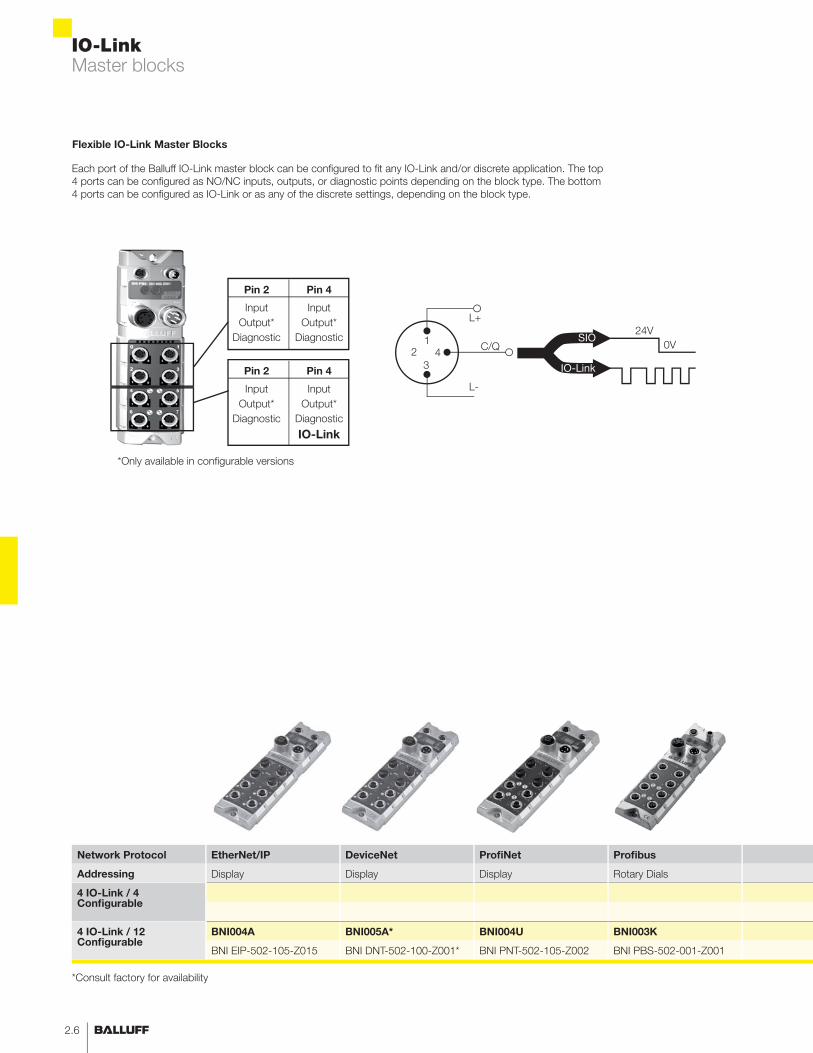
Network Protocol EtherNet/IP DeviceNet ProfiNet Profibus
Addressing Display Display Display Rotary Dials
4 IO-Link / 4 Configurable
4 IO-Link / 12 Configurable
BNI004A BNI005A* BNI004U BNI003K
BNI EIP-502-105-Z015 BNI DNT-502-100-Z001* BNI PNT-502-105-Z002 BNI PBS-502-001-Z001
Master blocks
Pin 2 Pin 4
Input Input
Output* Output*
Diagnostic Diagnostic
Pin 2 Pin 4
Input Input
Output* Output*
Diagnostic Diagnostic
IO-Link
Flexible IO-Link Master Blocks
1
3
2 4
L+
C/Q
L-
SIO
IO-Link
24V
0V
Each port of the Balluff IO-Link master block can be configured to fit any IO-Link and/or discrete application. The top
4 ports can be configured as NO/NC inputs, outputs, or diagnostic points depending on the block type. The bottom
4 ports can be configured as IO-Link or as any of the discrete settings, depending on the block type.
*Only available in configurable versions
*Consult factory for availability

www.balluff.com/networking
IO-Link
2.7
Profibus Profibus Profibus CC-Link
Display Rotary Dials Rotary Dials Display
BNI003P BNI0030
BNI PBS-507-001-Z011 BNI PBS-504-001-K008
BNI0040*
BNI PBS-502-101-Z001* BNI CCL-502-100-Z001*
Master blocks
Reduce CostsConnect devices with standard sensor/actuator cordset
Simplify cordset stocking with universal M12 standard
connectors on IO-Link devices
Secure investment with open standard, valid from all
manufacturers
Future-proof, with greatest flexibility in project planning
Reduce MaintenanceCapability of plug, play, and walk away
Automatic read adjustment of parameters
Reliable error detection
Troubleshoot a point-to-point connection,
rather than a network
Reduce Engineering and CommissioningCommissioning performed by the controller, not at each individual
IO-Link device
Scalability of each IO-Link port
Same architecture for different network protocols
Fewer network nodes and IP addresses to commission
Increase UptimeRecipe driven parameterization of IO-Link devices
Health diagnostics down to the IO-Link device level
Network cable can be removed from harsh areas, replaced by
standard sensor/actuator cordsets
Continuous monitoring of process parameters

IO-Link
2.8
Input/output devices
IO-Link Input/Output Devices
One of the major values of IO-Link over standard network I/O is the ability to run many sensors and actuators back
through one node or IP address. This is accomplished using the many varieties of I/O hubs offered by Balluff.
Multiple analog sensors can be run into an input hub with discrete inputs as well
Balluff’s full line of mini sensors can be run in small spaces using M8 hubs
Metal Inputs and Outputs allows for I/O in the most hostile environments
Standard sensors
in small places
One analog I/O channel
14 bit resolution
Inputs and outputs in
hostile environments
Prox mini.s
PF
Valve
connectors
Analog I/O devices
4 analog inputs
10 bit resolution plus
8 discrete inputs
Magneto-inductive
position sensor
www.balluff.com/networking
IO-Link
2.9
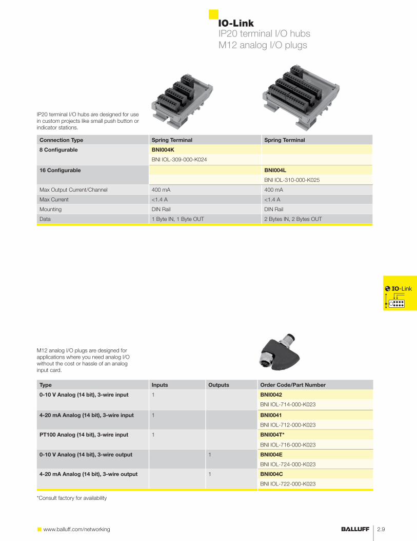
IP20 terminal I/O hubs
M12 analog I/O plugs
Type Inputs Outputs Order Code/Part Number
0-10 V Analog (14 bit), 3-wire input 1 BNI0042
BNI IOL-714-000-K023
4-20 mA Analog (14 bit), 3-wire input 1 BNI0041
BNI IOL-712-000-K023
PT100 Analog (14 bit), 3-wire input 1 BNI004T*
BNI IOL-716-000-K023
0-10 V Analog (14 bit), 3-wire output 1 BNI004E
BNI IOL-724-000-K023
4-20 mA Analog (14 bit), 3-wire output 1 BNI004C
BNI IOL-722-000-K023
M12 analog I/O plugs are designed for
applications where you need analog I/O
without the cost or hassle of an analog
input card.
*Consult factory for availability
Connection Type Spring Terminal Spring Terminal
8 Configurable BNI004K
BNI IOL-309-000-K024
16 Configurable BNI004L
BNI IOL-310-000-K025
Max Output Current/Channel 400 mA 400 mA
Max Current <1.4 A <1.4 A
Mounting DIN Rail DIN Rail
Data 1 Byte IN, 1 Byte OUT 2 Bytes IN, 2 Bytes OUT
IP20 terminal I/O hubs are designed for use
in custom projects like small push button or
indicator stations.

IO-Link
2.10
Type PNP Inputs Outputs M8 Plastic M8 Plastic M12 Plastic
Variation
Number of Ports 4 8 8
Max Output per port/per block -
3-wire input 4/8 - BNI000P BNI000R
BNI IOL-101-000-K018 BNI IOL-102-000-K019
3-wire input, w/diagnostics 4/8 - BNI001W BNI001Y
BNI IOL-101-S01-K018 BNI IOL-102-S01-K019
4-wire input 8/16 - BNI0021 BNI0005
BNI IOL-104-000-K021 BNI IOL-102-000-K006
4-wire input w/diagnostics 8/16 - BNI001Z* BNI0022
BNI IOL-102-S01-K020 BNI IOL-104-S01-K021
4-wire output - 8
4-wire output, w/diagnostics
- 8
5-wire input 16 - BNI0006
BNI IOL-104-000-K006
5-wire input, w/diagnostics 16 -
5-wire input, w/diagnostics, w/ID data
16 -
5-wire output - 16
5-wire output w/diagnostics - 16
5-wire configurable max 16 max 16
5-wire configurable, w/diagnostics
max 16 max 16
5-wire configurable, w/diagnostics, w/ID data
max 16 max 16
0-10 V analog (10 bit)
5-wire input
4x VDC
8x PNP
- BNI0008
BNI IOL-710-000-K006
4-20 mA analog (10 bit)
5-wire input
4x mA
8x PNP
- BNI0007
BNI IOL-709-000-K006
I/O hubs come in multiple form factors and
configurations and can be used for almost
any basic I/O applications, including analog
inputs.
M8 discrete I/O hubs
M12 discrete I/O hubs
M12 analog I/O hubs
*Consult factory for availability

www.balluff.com/networking
IO-Link
2.11
M12 Metal M12 Metal M12 Metal M12 Metal
with Integrated Power with 4-pole Auxilliary Power with 5-pole Auxilliary Power with Galvanic Isolation
8 8 8 8
0.5A / 1.4A 2A / 9A 2A / 9A 2A / 9A
BNI0031
BNI IOL-102-000-Z012
BNI0033
BNI IOL-252-000-Z013
BNI003W*
BNI IOL-252-S01-Z013
BNI0032
BNI IOL-104-000-Z012
BNI0039
BNI IOL-104-S01-Z012
BNI003T
BNI IOL-104-S01-Z012-C01
BNI0043 BNI0034
BNI IOL-205-000-Z012 BNI IOL-256-000-Z013
BNI003Y
BNI IOL-256-S01-Z013
BNI003U BNI0050* BNI0035
BNI IOL-302-000-Z012 BNI IOL-302-000-Z026 BNI IOL-302-000-Z013
BNI003C BNI0051* BNI003A
BNI IOL-302-S01-Z012 BNI IOL-302-S01-Z026 BNI IOL-302-S01-Z013
BNI0048
BNI IOL-302-S01-Z013-C01
M12 discrete I/O hubs

IO-Link
2.12
Intelligent sensors
Intelligent Sensors with IO-Link
As manufacturing needs to get more flexible, sensors and other devices installed in the process need to be flexible
as well. Right now, most production lines require the operator to reprogram a sensor, or the engineer needs to
design multiple sensors into the process. Intelligent sensors with IO-Link built into them can reduce this downtime
and the errors that come with reprogramming. IO-Link sensors can have their parameters changed via the PLC to
accommodate multiple recipes or configurations. Some examples of sensors with this capability are:
Color sensors for detecting product colors for error proofing or JIT (just in time) production
Measurement sensors for detecting the position of targets or measuring their size
Precision Mechanical Switches have been in the Balluff product portfolio from the very beginning,
use their upgraded functionality by connecting them via IO-Link
Edge detection sensors allow for positioning on machines or in production
Measurement
– Inductive
– Laser
EdgeMaster™
Edge detection
Five color sensing
Red Blue Yellow Green Gray
Mechanical switches
for position sensing
and triggering

www.balluff.com/networking
IO-Link
2.13
Edge detection and mechanical switches
Edge Detection
30 mm BGL0035
BGL 30C-007-S4
50 mm BGL003F
BGL 50C-007-S4
Resolution 0.08 mm
Light Spot 28 mm x 3 mm
Air Blowoff Built-in
Analog Valve Range 0...1024
Edge position detection is a vital sensor
application in many industries from paper
or laminates, to steel moving into presses.
The exact edge position is vital to efficient
automation.
Mechanical Switches
Part Number BNS 819-...
Housing Series Available 40, 46, 61, 62, 100
To select an exact part number,
visit www.balluff.com/bns

IO-Link
2.14
Inductive Positioning Sensors
Order Code BIP0004
Part Number BIP LD2-T040-02-S4
Range 0...40 mm
Target Width 14 mm
Resolution 40 μm
Process Data 2 bytes
Measurement sensorsPositioning sensors
Inductive Measurement Sensors
Order Code BAW002F BAW003A
Part Number BAW M18MI-BLC50B-S04G BAW Z01AC-BLD50B-DP03
Range 1...5 mm 1...5 m
Switch Points 0 3
Resolution ± 8 μm ± 10 μm
Analog Value Range 0000...03FF 0000...03FF
Process Data 3 bytes 2 bytes
www.balluff.com/networking
IO-Link
2.15
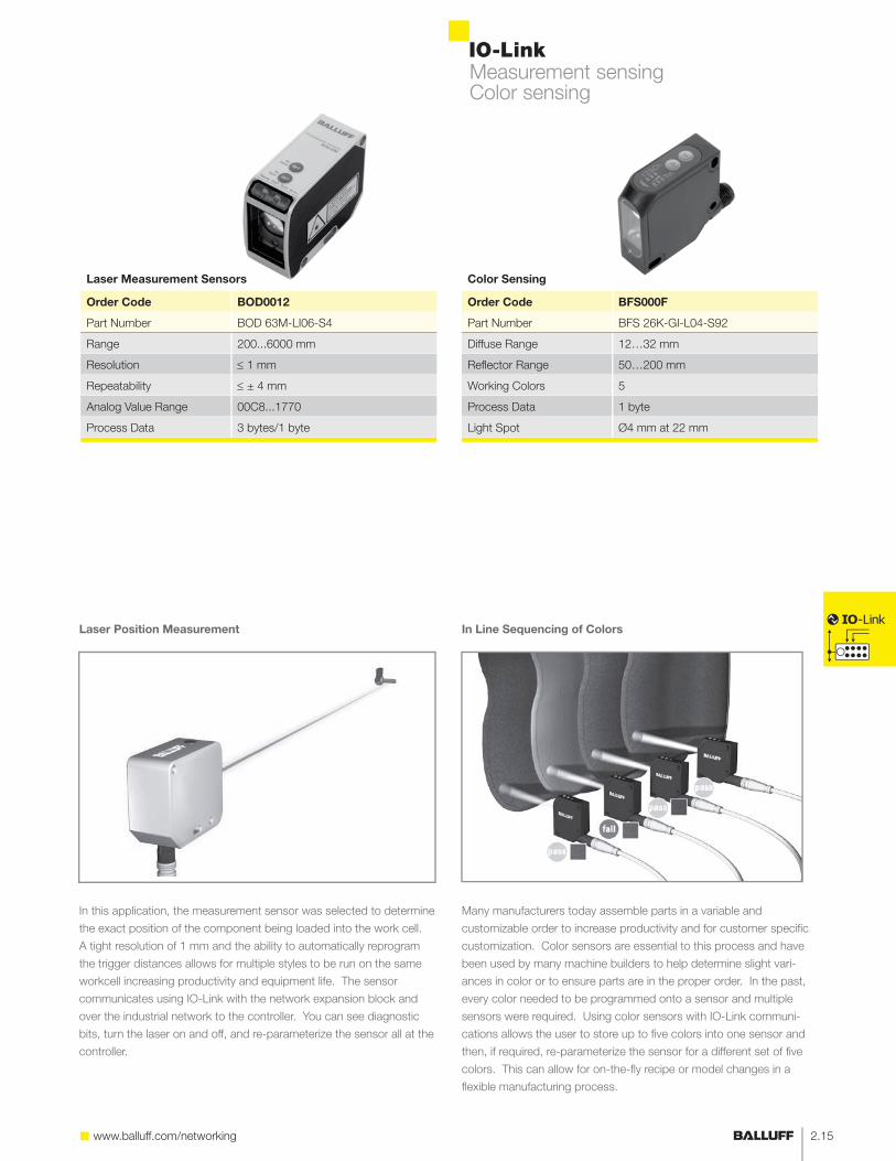
Color Sensing
Order Code BFS000F
Part Number BFS 26K-GI-L04-S92
Diffuse Range 12…32 mm
Reflector Range 50…200 mm
Working Colors 5
Process Data 1 byte
Light Spot Ø4 mm at 22 mm
Measurement sensingColor sensing
In this application, the measurement sensor was selected to determine
the exact position of the component being loaded into the work cell.
A tight resolution of 1 mm and the ability to automatically reprogram
the trigger distances allows for multiple styles to be run on the same
workcell increasing productivity and equipment life. The sensor
communicates using IO-Link with the network expansion block and
over the industrial network to the controller. You can see diagnostic
bits, turn the laser on and off, and re-parameterize the sensor all at the
controller.
Many manufacturers today assemble parts in a variable and
customizable order to increase productivity and for customer specific
customization. Color sensors are essential to this process and have
been used by many machine builders to help determine slight vari-
ances in color or to ensure parts are in the proper order. In the past,
every color needed to be programmed onto a sensor and multiple
sensors were required. Using color sensors with IO-Link communi-
cations allows the user to store up to five colors into one sensor and
then, if required, re-parameterize the sensor for a different set of five
colors. This can allow for on-the-fly recipe or model changes in a
flexible manufacturing process.
Laser Position Measurement In Line Sequencing of Colors
Laser Measurement Sensors
Order Code BOD0012
Part Number BOD 63M-LI06-S4
Range 200...6000 mm
Resolution 1 mm
Repeatability ± 4 mm
Analog Value Range 00C8...1770
Process Data 3 bytes/1 byte

IO-Link
2.16
Data Tracking with Industrial RFID using IO-Link
In today’s manufacturing environment, it is becoming more and more important to track every step of the production process.
Many manufacturers have installed barcode systems or hand written paper work filed by operators or maintenance crews.
This can be time consuming and prone to failure. Industrial RFID systems can be used to track production data and record
plant floor information in every step of the process. There are two main ways to track part data.
Centralized Data Tracking: All of the information is stored in a central computer and the RFID system is
used only for identification of the part in the work cell. This is a very similar concept to barcoding, but it is more
rugged and 100% reliable. (Read Only Systems)
Decentralized Data Tracking: Data per part is stored on the RFID tag and is written to the tag at each
workstation. This concept allows for the data to always stay with the part throughout the production process.
Radio frequency identification
Read only systems (BIS L)
For centralized data tracking
Modular base
with different heads
Read/Write systems (BIS M)
For decentralized data tracking
Longest range
Metal mounted tags
BIS L-203-03/L
BIS L-201-03/L
BIS M-112-02/L
BIS M-151-02/A
0...65 mm
0...38 mm
0...35 mm
0...7 mm

www.balluff.com/networking
IO-Link
2.17
RFID read-only systems
Size M12 M18 25x50 40x40
IO-Link Processors
Read only
BIS00E1 BIS00E0 BIS00E2 BIS00CZ
BIS L-409-045-003-07-S4 BIS L-409-045-002-07-S4 BIS L-409-045-004-07-S4 BIS L-409-045-001-07-S4
Da
ta C
arr
iers
BIS0035 --- 0...15 mm 0...15 mm 0...25 mm
BIS L-100-05/L-RO
BIS0038 --- 0...18 mm 0...18 mm 0...35 mm
BIS L-101-05/L-RO
BIS003C --- --- --- 0...48 mm
BIS L-102-05/L-RO
BIS003F 0...7 mm 0...10 mm 0...10 mm 0...16 mm
BIS L-103-05/L-RO
BIS003R --- 0…15 mm 0…15 mm 0…25 mm
BIS L-200-03/L
BIS003T --- 0…18 mm 0…18 mm 0…35 mm
BIS L-201-03/L
BIS003U --- --- --- 0…48 mm
BIS L-202-03/L
BIS003W 0…7 mm 0…10 mm 0… 10 mm 0…16 mm
BISL-203-03/L
Note:
The BIS L-1_ _-05/L-RO uses a single write data carrier with 192 bytes.
The BIS L-2_ _-03/L uses read only data carriers with a fixed “unique number” of five bytes (40 bits).
No repetition of the unique number or delivery of sequential numbers is possible.
All IO-Link RFID processors require a shielded cable. See page 2.19 for suggested part numbers.
Select your RFID system in 4 easy steps:
1. Decide whether you need to write data to a data carrier.
Yes see page 2.18
No see page 2.17
2. Choose the appropriate data carrier form factor.
3. Determine the head based on distance.
4. Determine your required memory capacity.

IO-Link
2.18
RFID read/write systemsStandard and metal mount data carriers
Size M15.5 M18
IO-Link Processors
Read/Write Heads
BIS00LJ BIS00LW
BIS M-400-045-002-07-S4 BIS M-402-045-002-07-S4
Sta
nd
ard
Da
ta C
arr
iers
752 bytes 2000 bytes
BIS0048 BIS004A 0…5(6) mm 0…5 mm
BIS M-122-01/A BIS M-122-02/A
BIS0040 BIS0042 0…6(9) mm 0…5 mm
BIS M-105-01/A BIS M-105-02/A
BIS0044 0…15 mm 0…8 mm
BIS M-110-02/L
BIS003Y 0…15 mm
BIS M-101-01/L
BIS003Z 0…18 mm
BIS M-102-01/L
BIS0043 0…20 m
BIS M-108-02/L
BIS0045 0…20 mm
BIS M-111-02/L
BIS0046 0…28 mm
BIS M-112-02/L
BIS0047
BIS M-120-01/L
Size 80x84
IO-Link Processors
Read/Write Heads
BIS00LM
BIS M-451-045-001-07-S4
Me
tal M
ou
nt
Da
taC
arr
iers BIS004F 0…65 mm
BIS M-150-02/A (vertical mount)
BIS004H 0…65 mm
BIS M-151-02/A (horizontal mount)
For reliable traceability: All data carriers have a 4-byte unique ID contained in the read/write memory. This number is read-only.
All IO-Link RFID processors require a shielded cable. See page 2.19 for suggested part numbers.
Metal Mount Series: These tags provide highly reliable RFID performance mounted on any metal surface.
Features: - No reduction in range, regardless of metal alloy - Large read/write range - Compatible with all M processors
Metal mounting plate 40x22mm BIS Z-MP-001 please order separately (10 to a package). Required if no metal substrate is used.

www.balluff.com/networking
IO-Link
2.19
RFID read/write systemsShielded cable options
M30 25x50 80x84
BIS00LH BIS00M1 BIS00LK
BIS M-400-045-001-07-S4 BIS M-402-045-004-07-S4 BIS M-401-045-001-07-S4
0...5 (8) mm
0…7(11) mm 0...6 (8) mm
0…20 mm 0...15 mm 0…30 mm
0…20 mm 0…28 mm
0…28 mm 0…45 mm
0…28 mm 0…40 mm
0…28 mm 0…40 mm
0…38 mm 0…60 mm
0…50 mm
Shielded Cable Options
Size M12 - M12 M12
Configuration Female - Male Female with Male Field Attachable
Jacket Shielded PUR Black Shielded PUR Black
Conductors 4x 0.34 mm² 4x 0.34 mm²
Available Lengths 1 m, 2 m, 2.5 m, 5 m 2 m, 5 m, 10 m, 20 m
Double-Ended Straight-Straight BCC M415-M414-3A-305-PS0434-_ _ _*
Single-Ended Straight Female BCC M415-0000-1A-014-PS0434-_ _ _
Single-Ended Right Angle Female BCC M425-0000-1A-014-PS0434-_ _ _
Field Attachable Straight Male BCC M474-0000-2A-000-01X475-000
* 010 = 1 m, 020 = 2 m, 025 = 2.5 m, 050 = 5 m, 100 = 10 m

IO-Link
2.20
IO-Link connection devices
Connectivity Products with IO-Link
IO-Link’s versatility can be seen in the deep product offering covered in these pages. There are times when a standard
sensor cable is just not enough. Maybe you need to have I/O on constantly changing end effectors or a rotating fixture.
Valve banks with built in network control can add additional costs to a project. Then there are the times you wish you
could just hook the device to your computer, just to get that extra bit of interaction with the device. All of these things
are capable with IO-Link by Balluff.
Non-contact connectors allow for quick change out and free rotation without loss of power or signal
Remove costly valve bank network controllers and go to an intelligent 25-pin D-sub connector
Connect directly to any IO-Link device with your computer for easy setup or parameterization
Non-contact connectors
25-pin D-sub valve
manifold connector
Mechanical switches
(see page 2.13)USB IO-Link Master for
parameterization or
reviewing components
USB to PC
Standard 16 input I/O hub

www.balluff.com/networking
IO-Link
2.21
Non-contact connectors USB master
Non-Contact Connectors
Base BIC005A BIC000C BIC0053
BIC 1I0-I2A50-Q40KFU-SM4A4A BIC 1I0-I2A50-M30MI3-SM4A4A BIC 1I0-IAA50-M30MI3-SM4A4A
Remote BIC005C BIC000E BIC0054
BIC 2I0-I2A50-Q40KFU-SM4A5A BIC 2I0-I2A50-M30MI3-SM4A5A BIC 2I0-IAA50-M30I3-SM4A5A
Housing Type 40x40 M30 M30
Remote Side, Max Current 500 mA 500 mA 500 mA
Transmission Range 0...5 mm 0…5 mm 0...5 mm
Max Data Transmitted 3 bytes 3 bytes 10 bytes
Process Data 4 bytes 4 bytes 11 bytes
For more information on applications for these products, visit section 4
USB Master
USB Master BNI002U
BNI USB-901-000-A501
Number of IO-Link Ports 1
USB, Max Current 50 mA
External Power, Max Current 1.6 A
Software Included Yes
USB Master Features:
- Standard parameterization
- Troubleshooting by device
- PC backup of parameter data
BIC000C BIC0053

IO-Link
2.22
2 Byte with Output Master Control BNI001L
BNI IOL-751-V02-K007
3 Byte with Output Master Control BNI001K
BNI IOL-751-V01-K007
6 Byte with Output Master Control,
with Open Coil Detection
Connection Type 25-pin D-Sub 25-pin D-Sub
Pin Configuration Pin1: Coil1: Address0
Pin2: Coil2: Address1
Pin25: 0V
Pin1: Coil1: Slot1
Pin2: Coil2: Slot1
Pin25: 0V
Max Current 1.6A 1.6A
Max Number of Pistons 24 max 16 max
Valve Models Festo MPA
Bosch Rexroth LS04, HFO2-LG, HFO3-LG, HF04
Festo CPV
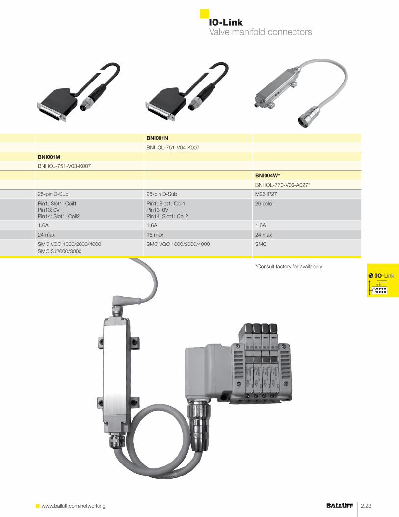
Valve manifold connectors
Note:
- Must be used with configurable IO-Link expansion module
- Source power: auxiliary output power
www.balluff.com/networking
IO-Link
2.23
BNI001N
BNI IOL-751-V04-K007
BNI001M
BNI IOL-751-V03-K007
BNI004W*
BNI IOL-770-V06-A027*
25-pin D-Sub 25-pin D-Sub M26 IP27
Pin1: Slot1: Coil1
Pin13: 0V
Pin14: Slot1: Coil2
Pin1: Slot1: Coil1
Pin13: 0V
Pin14: Slot1: Coil2
26 pole
1.6A 1.6A 1.6A
24 max 16 max 24 max
SMC VQC 1000/2000/4000
SMC SJ2000/3000
SMC VQC 1000/2000/4000 SMC
Valve manifold connectors
*Consult factory for availability