1746-IN027D-EN-P SLC 500 Digital I/O Modules … · Installation Instructions SLC 500 Digital I/O...
48
Installation Instructions SLC 500 Digital I/O Modules Input Catalog Numbers 1746-IA4, 1746-IA8, 1746-IA16, 1746-IB8, 1746-IB16, 1746-IC16, 1746-IG16, 1746-IH16, 1746-IM4, 1746-IM8, 1746-IM16, 1746-IN16, 1746-ITB16, 1746-ITV16, 1746-IV8, 1746-IV16 Output Catalog Numbers 1746-OA8, 1746-OA16, 1746-OAP12, 1746-OB8, 1746-OB6EI, 1746-OB16, 1746-OB16E, 1746-OBP8, 1746-OBP16, 1746-OG16, 1746-OV8, 1746-OV16, 1746-OVP16, 1746-OW4, 1746-OW8, 1746-OW16, 1746-OX8 Combination Input/Output Catalog Numbers 1746-IO4, 1746-IO8, 1746-IO12, 1746-IO12DC Table of Contents Topic Page Important User Information 2 North American Hazardous Location Approval 3 Environment and Enclosure 4 Prevent Electrostatic Discharge 4 Install and Remove the Module 5 Octal Label Kit Installation (for PLC processors only) 6 Wiring Diagrams 17 Apply the Octal Filter Label 6 Apply the Octal Door Label 6 Removable Terminal Blocks 6 Recovery From Blown Fuse/Processor Fault/Processor Shutdown 13 Replacement Fuse Recommendations 13 Replace Fuses 14 Electronically Protected Modules (1746-OB6EI and 1746-OB16E) 14 Specifications 29
Transcript of 1746-IN027D-EN-P SLC 500 Digital I/O Modules … · Installation Instructions SLC 500 Digital I/O...
Installation Instructions
SLC 500 Digital I/O Modules
Input Catalog Numbers 1746-IA4, 1746-IA8, 1746-IA16, 1746-IB8, 1746-IB16, 1746-IC16, 1746-IG16, 1746-IH16, 1746-IM4, 1746-IM8, 1746-IM16, 1746-IN16, 1746-ITB16, 1746-ITV16, 1746-IV8, 1746-IV16Output Catalog Numbers 1746-OA8, 1746-OA16, 1746-OAP12, 1746-OB8, 1746-OB6EI, 1746-OB16, 1746-OB16E, 1746-OBP8, 1746-OBP16, 1746-OG16, 1746-OV8, 1746-OV16, 1746-OVP16, 1746-OW4, 1746-OW8, 1746-OW16, 1746-OX8Combination Input/Output Catalog Numbers 1746-IO4, 1746-IO8, 1746-IO12, 1746-IO12DC Table of Contents
Topic Page
Important User Information 2
North American Hazardous Location Approval 3
Environment and Enclosure 4
Prevent Electrostatic Discharge 4
Install and Remove the Module 5
Octal Label Kit Installation (for PLC processors only) 6
Wiring Diagrams 17
Apply the Octal Filter Label 6
Apply the Octal Door Label 6
Removable Terminal Blocks 6
Recovery From Blown Fuse/Processor Fault/Processor Shutdown 13
Replacement Fuse Recommendations 13
Replace Fuses 14
Electronically Protected Modules (1746-OB6EI and 1746-OB16E) 14
Specifications 29
2 SLC 500 Digital I/O Modules
Important User Information
OverviewIn addition to providing the module’s electrical specifications, this document tells you how to:
• install the module into a chassis.• wire the module’s terminal block.• install the Octal Filter Label.
Solid-state equipment has operational characteristics differing from those of electromechanical equipment. Safety Guidelines for the Application, Installation and Maintenance of Solid State Controls (Publication SGI-1.1 available from your local Rockwell Automation sales office or online at http://www.rockwellautomation.com/literature/) describes some important differences between solid-state equipment and hard-wired electromechanical devices. Because of this difference, and also because of the wide variety of uses for solid-state equipment, all persons responsible for applying this equipment must satisfy themselves that each intended application of this equipment is acceptable.
In no event will Rockwell Automation, Inc. be responsible or liable for indirect or consequential damages resulting from the use or application of this equipment.
The examples and diagrams in this manual are included solely for illustrative purposes. Because of the many variables and requirements associated with any particular installation, Rockwell Automation, Inc. cannot assume responsibility or liability for actual use based on the examples and diagrams.
No patent liability is assumed by Rockwell Automation, Inc. with respect to use of information, circuits, equipment, or software described in this manual.
Reproduction of the contents of this manual, in whole or in part, without written permission of Rockwell Automation, Inc., is prohibited.
Throughout this manual, when necessary, we use notes to make you aware of safety considerations.
WARNING: Identifies information about practices or circumstances that can cause an explosion in a hazardous environment, which may lead to personal injury or death, property damage, or economic loss.
ATTENTION: Identifies information about practices or circumstances that can lead to personal injury or death, property damage, or economic loss. Attentions help you identify a hazard, avoid a hazard and recognize the consequences.
SHOCK HAZARD: Labels may be on or inside the equipment (for example, drive or motor) to alert people that dangerous voltage may be present.
BURN HAZARD: Labels may be on or inside the equipment (for example, drive or motor) to alert people that surfaces may reach dangerous temperatures.
IMPORTANT Identifies information that is critical for successful application and understanding of the product.
Publication 1746-IN027D-EN-P - December 2012
SLC 500 Digital I/O Modules 3
North American Hazardous Location ApprovalThe following modules are North American Hazardous Location approved: 1746-IA4, 1746-IA8, 1746-IA16, 1746-IB8, 1746-IB16, 1746-IC16, 1746-IG16, 1746-IH16, 1746-IM4, 1746-IM8, 1746-IM16, 1746-IN16, 1746-ITB16, 1746-ITV16, 1746-IV8, 1746-IV16, 1746-OA8, 1746-OA16, 1746-OAP12, 1746-OB8, 1746-OB6EI, 1746-OB16, 1746-OB16E, 1746-OBP8, 1746-OBP16, 1746-OG16, 1746-OV8, 1746-OV16, 1746-OVP16, 1746-OW4, 1746-OW8, 1746-OW16, 1746-OX8, 1746-IO4, 1746-IO8, 1746-IO12, 1746-IO12DC.
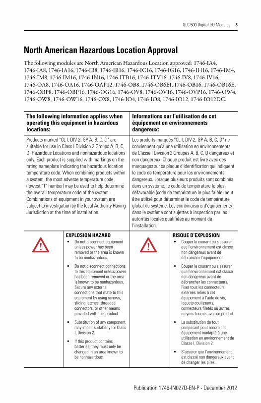
The following information applies when operating this equipment in hazardous locations:
Informations sur l’utilisation de cet équipement en environnements dangereux:
Products marked "CL I, DIV 2, GP A, B, C, D" are suitable for use in Class I Division 2 Groups A, B, C, D, Hazardous Locations and nonhazardous locations only. Each product is supplied with markings on the rating nameplate indicating the hazardous location temperature code. When combining products within a system, the most adverse temperature code (lowest "T" number) may be used to help determine the overall temperature code of the system. Combinations of equipment in your system are subject to investigation by the local Authority Having Jurisdiction at the time of installation.
Les produits marqués "CL I, DIV 2, GP A, B, C, D" ne conviennent qu'à une utilisation en environnements de Classe I Division 2 Groupes A, B, C, D dangereux et non dangereux. Chaque produit est livré avec des marquages sur sa plaque d'identification qui indiquent le code de température pour les environnements dangereux. Lorsque plusieurs produits sont combinés dans un système, le code de température le plus défavorable (code de température le plus faible) peut être utilisé pour déterminer le code de température global du système. Les combinaisons d'équipements dans le système sont sujettes à inspection par les autorités locales qualifiées au moment de l'installation.
EXPLOSION HAZARD• Do not disconnect equipment
unless power has been removed or the area is known to be nonhazardous.
• Do not disconnect connections to this equipment unless power has been removed or the area is known to be nonhazardous. Secure any external connections that mate to this equipment by using screws, sliding latches, threaded connectors, or other means provided with this product.
• Substitution of any component may impair suitability for Class I, Division 2.
• If this product contains batteries, they must only be changed in an area known to be nonhazardous.
RISQUE D’EXPLOSION• Couper le courant ou s'assurer
que l'environnement est classé non dangereux avant de débrancher l'équipement.
• Couper le courant ou s'assurer que l'environnement est classé non dangereux avant de débrancher les connecteurs. Fixer tous les connecteurs externes reliés à cet équipement à l'aide de vis, loquets coulissants, connecteurs filetés ou autres moyens fournis avec ce produit.
• La substitution de tout composant peut rendre cet équipement inadapté à une utilisation en environnement de Classe I, Division 2.
• S'assurer que l'environnement est classé non dangereux avant de changer les piles.
Publication 1746-IN027D-EN-P - December 2012
4 SLC 500 Digital I/O Modules
Environment and Enclosure
Prevent Electrostatic Discharge
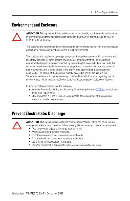
ATTENTION: This equipment is intended for use in a Pollution Degree 2 industrial environment, in overvoltage Category II applications (as defined in IEC 60664-1), at altitudes up to 2000 m (6562 ft) without derating.
This equipment is not intended for use in residential environments and may not provide adequate protection to radio communication services in such environments.
This equipment is supplied as open-type equipment. It must be mounted within an enclosure that is suitably designed for those specific environmental conditions that will be present and appropriately designed to prevent personal injury resulting from accessibility to live parts. The enclosure must have suitable flame-retardant properties to prevent or minimize the spread of flame, complying with a flame spread rating of 5VA or be approved for the application if nonmetallic. The interior of the enclosure must be accessible only by the use of a tool. Subsequent sections of this publication may contain additional information regarding specific enclosure type ratings that are required to comply with certain product safety certifications.
In addition to this publication, see the following:• Industrial Automation Wiring and Grounding Guidelines, publication 1770-4.1, for additional
installation requirements.• NEMA Standard 250 and IEC 60529, as applicable, for explanations of the degrees of
protection provided by enclosures.
ATTENTION: This equipment is sensitive to electrostatic discharge, which can cause internal damage and affect normal operation. Follow these guidelines when you handle this equipment:
• Touch a grounded object to discharge potential static.• Wear an approved grounding wriststrap.• Do not touch connectors or pins on component boards.• Do not touch circuit components inside the equipment.• Use a static-safe workstation, if available.• Store the equipment in appropriate static-safe packaging when not in use.
Publication 1746-IN027D-EN-P - December 2012
SLC 500 Digital I/O Modules 5
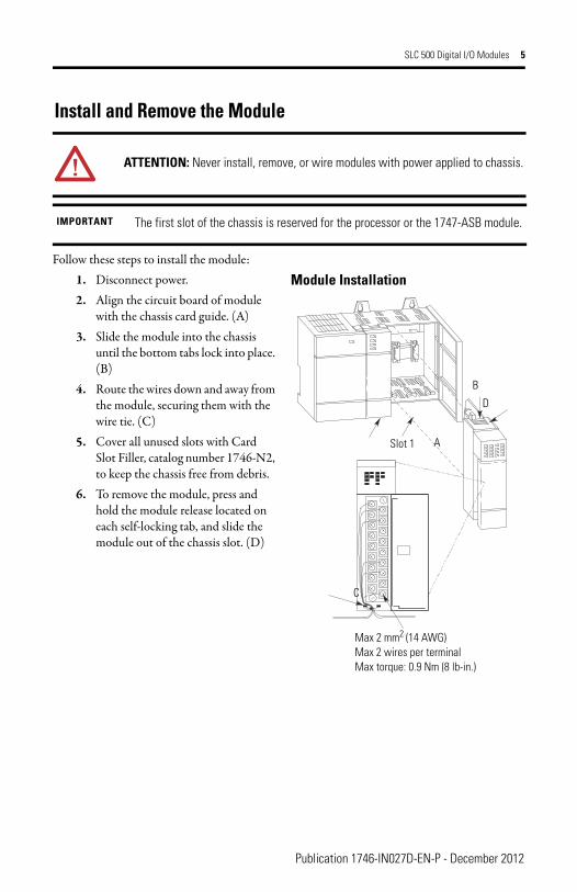
Install and Remove the Module
Follow these steps to install the module:
ATTENTION: Never install, remove, or wire modules with power applied to chassis.
IMPORTANT The first slot of the chassis is reserved for the processor or the 1747-ASB module.
Slot 1 A
B
D
C
Max 2 mm2 (14 AWG)Max 2 wires per terminalMax torque: 0.9 Nm (8 lb-in.)
1. Disconnect power.2. Align the circuit board of module
with the chassis card guide. (A)3. Slide the module into the chassis
until the bottom tabs lock into place. (B)
4. Route the wires down and away from the module, securing them with the wire tie. (C)
5. Cover all unused slots with Card Slot Filler, catalog number 1746-N2, to keep the chassis free from debris.
6. To remove the module, press and hold the module release located on each self-locking tab, and slide the module out of the chassis slot. (D)
Module Installation
Publication 1746-IN027D-EN-P - December 2012

6 SLC 500 Digital I/O Modules
Octal Label Kit Installation (for PLC processors only)The octal label kit consists of an octal filter label and a door label. Use these octal labels to replace the decimal labels that are attached to the I/O modules.
Apply the Octal Filter Label
1. Remove the octal filter label from its paper carrier. 2. Align the octal filter label numbers horizontally to the module color bar and over the
decimal filter numbers.Refer to Installing Octal Labels on page 7 for filter label placement.
3. Apply the octal label to the filter.4. Press firmly to be sure that the label adheres properly.
Apply the Octal Door Label
1. Remove the octal door label from its paper carrier.2. Align the octal label directly over the decimal door label on the inside of the door.
Refer to Installing Octal Labels on page 7 for door label placement.3. Press firmly to be sure that the label adheres properly.
Removable Terminal BlocksColored terminal blocks are removable by loosening the upper and lower retaining screws. Black terminal blocks are not removable.
TIP The octal label kit can be obtained from your Allen-Bradley distributor. The octal kit is ordered based on the catalog number of the I/O module.
Please refer to the SLC 500 Modular Hardware Style User Manual, publication 1747-UM011, for a listing of octal label kit catalog numbers.
ATTENTION: Do not touch or remove the terminal block when the SLC 500 system is powered. Contact with AC line potential may cause injury to personnel.
Publication 1746-IN027D-EN-P - December 2012
SLC 500 Digital I/O Modules 7
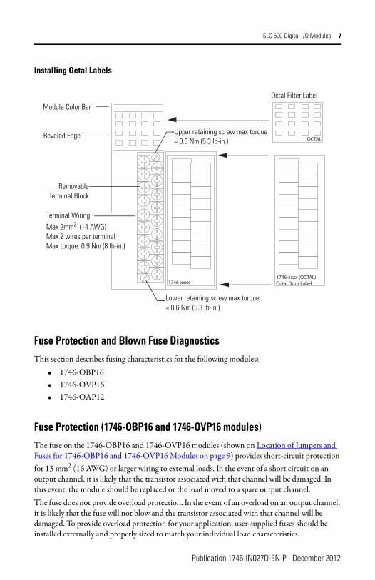
Installing Octal Labels
Fuse Protection and Blown Fuse Diagnostics This section describes fusing characteristics for the following modules:
• 1746-OBP16• 1746-OVP16• 1746-OAP12
Fuse Protection (1746-OBP16 and 1746-OVP16 modules)The fuse on the 1746-OBP16 and 1746-OVP16 modules (shown on Location of Jumpers and Fuses for 1746-OBP16 and 1746-OVP16 Modules on page 9) provides short-circuit protection for 13 mm2 (16 AWG) or larger wiring to external loads. In the event of a short circuit on an output channel, it is likely that the transistor associated with that channel will be damaged. In this event, the module should be replaced or the load moved to a spare output channel.The fuse does not provide overload protection. In the event of an overload on an output channel, it is likely that the fuse will not blow and the transistor associated with that channel will be damaged. To provide overload protection for your application, user-supplied fuses should be installed externally and properly sized to match your individual load characteristics.
OCTAL
1746-xxxx (OCTAL)Octal Door Label1746-xxxx
Octal Filter Label
Upper retaining screw max torque= 0.6 Nm (5.3 lb-in.)
Module Color Bar
Lower retaining screw max torque= 0.6 Nm (5.3 lb-in.)
RemovableTerminal Block
Beveled Edge
Terminal Wiring
Max 2mm2 (14 AWG)Max 2 wires per terminalMax torque: 0.9 Nm (8 lb-in.)
Publication 1746-IN027D-EN-P - December 2012
8 SLC 500 Digital I/O Modules
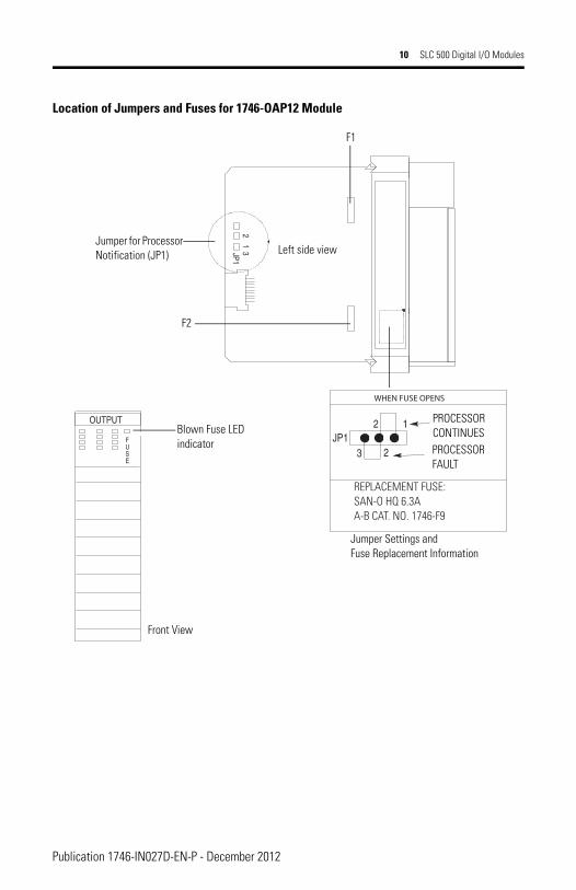
Fuse Protection (1746-OAP12 modules)A fuse is provided on each common of the 1746-OAP12 module (shown on Location of Jumpers and Fuses for 1746-OAP12 Module on page 10) for a total of two fuses. The fuses are designed to protect the module from short-circuit conditions. The fuse does not provide overload protection. In the event of an overload on an output channel, it is likely that the fuse will not blow and the output device associated with that channel will be damaged. To provide overload protection for your application, user-supplied fuses should be installed externally.The recommended fuse for overload protection is SAN-O HT. Select the fuse rating according to your load. Do not use HT fuses rated higher than 2.0 Amps.
Blown Fuse DiagnosticsIf the fuse blows on the 1746-OBP16, 1746-OVP16, or 1746-OAP12 module, the following occurs:
• The blown fuse LED indicator will illuminate, provided power (5V DC via backplane and load power via external supply) is applied to the module.
• A processor error will occur if JP1 connects pins 2 and 3. (See figures on page 9 and page 10.)
Publication 1746-IN027D-EN-P - December 2012
SLC 500 Digital I/O Modules 9
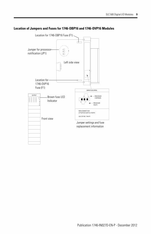
Location of Jumpers and Fuses for 1746-OBP16 and 1746-OVP16 Modules
FUSE
OUTPUT
WHEN FUSE OPENS
PROCESSORCONTINUES
PROCESSORFAULTS
REPLACEMENT FUSELITTLEFUSE 322010 or 332010
A.B. CAT. NO. 1746-F9
3 2
2 1
12
3
Left side view
Location for 1746-OBP16 Fuse (F1)
Jumper for processor notification (JP1)
Brown fuse LEDIndicator
Jumper settings and fuse replacement information
Location for 1746-OVP16 Fuse (F1)
Front view
Publication 1746-IN027D-EN-P - December 2012
10 SLC 500 Digital I/O Modules
Location of Jumpers and Fuses for 1746-OAP12 Module
12
3
OUTPUT
1JP1
23
JP1FUSE
REPLACEMENT FUSE:SAN-O HQ 6.3AA-B CAT. NO. 1746-F9
2
WHEN FUSE OPENS
F1
F2
Jumper for Processor Notification (JP1) Left side view
PROCESSORCONTINUESPROCESSORFAULT
Jumper Settings and Fuse Replacement Information
Blown Fuse LEDindicator
Front View
Publication 1746-IN027D-EN-P - December 2012
SLC 500 Digital I/O Modules 11
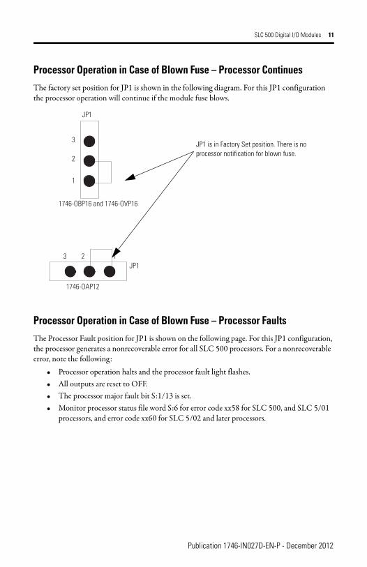
Processor Operation in Case of Blown Fuse – Processor ContinuesThe factory set position for JP1 is shown in the following diagram. For this JP1 configuration the processor operation will continue if the module fuse blows.
Processor Operation in Case of Blown Fuse – Processor FaultsThe Processor Fault position for JP1 is shown on the following page. For this JP1 configuration, the processor generates a nonrecoverable error for all SLC 500 processors. For a nonrecoverable error, note the following:
• Processor operation halts and the processor fault light flashes.• All outputs are reset to OFF.• The processor major fault bit S:1/13 is set.• Monitor processor status file word S:6 for error code xx58 for SLC 500, and SLC 5/01
processors, and error code xx60 for SLC 5/02 and later processors.
JP1
3 2 1JP1
1
2
3
1746-OAP12
1746-OBP16 and 1746-OVP16
JP1 is in Factory Set position. There is no processor notification for blown fuse.
Publication 1746-IN027D-EN-P - December 2012
12 SLC 500 Digital I/O Modules
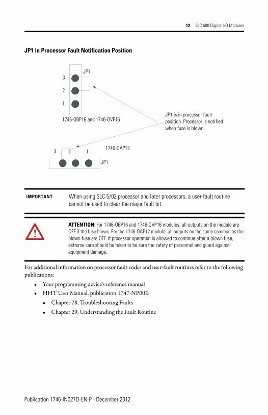
JP1 in Processor Fault Notification Position
For additional information on processor fault codes and user-fault routines refer to the following publications:
• Your programming device’s reference manual• HHT User Manual, publication 1747-NP002:
• Chapter 28, Troubleshooting Faults• Chapter 29, Understanding the Fault Routine
IMPORTANT When using SLC 5/02 processor and later processors, a user-fault routine cannot be used to clear the major fault bit.
ATTENTION: For 1746-OBP16 and 1746-OVP16 modules, all outputs on the module are OFF if the fuse blows. For the 1746-OAP12 module, all outputs on the same common as the blown fuse are OFF. If processor operation is allowed to continue after a blown fuse, extreme care should be taken to be sure the safety of personnel and guard against equipment damage.
JP1 is in processor fault position. Processor is notified when fuse is blown.
JP1
1
2
3
1746-OBP16 and 1746-OVP16
1746-OAP12123
JP1
Publication 1746-IN027D-EN-P - December 2012
SLC 500 Digital I/O Modules 13
The following table defines operation of all SLC 500 processors in the case of a blown fuse in 1746-OBP16, 1746-OVP16, and 1746-OAP12 modules.
Recovery From Blown Fuse/Processor Fault/Processor ShutdownProcessor operation will stop under the following conditions:
• The output module fuse blows due to a short circuit.• JP1 is set to the Processor Faults position (pins 2 and 3 connected).
If the above conditions occur, the following procedures should be used for recovery.
1. Follow fuse replacement procedures described on page 14. 2. Clear the processor major fault bit S:1/13.3. Clear processor status file S:6 major error code (optional).4. Return the processor to Run mode.
For additional information on processor fault codes and clearing processor fault bits, refer to the following user manuals:
• Your programming device’s reference manual• HHT User Manual, publication 1747-NP002
• Chapter 28, Troubleshooting Fault• Chapter 29, Understanding the Fault Routine
Replacement Fuse RecommendationsUse the following replacement fuses:
• 1746-OBP16 and 1746-OVP16 modules – Littelfuse #322010,10A or #332010,10A. This fuse is required to maintain UL/CSA rating. Replacement Fuse Kit is catalog number 1746-F8 (five fuses per kit).
• 1746-OAP12 module - Use SAN-O HQ 6.3A for replacement. This fuse is required to maintain UL/CSA rating. Replacement Fuse Kit is catalog number 1746-F9 (five fuses per kit).
Processor Operation After a Blown Fuse (1746-OBP16, 1746-OVP16, and 1746-OAP12 modules)
JP1 Set to Processor Continues JP1 Set to Processor Faults
No error. Processor continues with 1746-OBP16 and 1746-OVP16 outputs de-energized. 1746-OAP12 outputs, on the same common as the blown fuse, are de-energized.
Nonrecoverable error. Processor operations stop and all outputs reset to OFF.
Publication 1746-IN027D-EN-P - December 2012
14 SLC 500 Digital I/O Modules
Replace Fuses
1. Remove SLC 500 system power and correct the conditions causing the short circuit.2. Remove the output module from the chassis.3. Remove the fuse.
• 1746-OBP16 and 1746-OVP16 modules: Use a wide-tipped, slotted-head screwdriver to remove the blown fuse. Slide the screwdriver tip under the fuse and use a twisting motion to pry the fuse from the fuse clip. Use care so that the printed circuit board and surrounding electronics are not damaged.
• 1746-OAP12 module: A fuse holder is provided with each fuse. Simply grasp the fuse holder with needle-nose pliers, or your fingers, and pull it out.
4. Replace the fuse.• 1746-OBP16 and 1746-OVP16 modules: Center the replacement fuse over the fuse
clip and press down. If you use a tool to press the fuse in place, apply pressure to the metal end caps only, not the center of the fuse.
• 1746-OAP12 module: Insert a new fuse into the fuse holder, align the fuse holder on fuse clips, and press down.
5. Replace the output module in the chassis.6. Restore SLC 500 system power. 7. Clear processor fault bits as indicated in the steps provided on page 13.
Electronically Protected Modules (1746-OB6EI and 1746-OB16E)The electronic protection of the 1746-OB6EI and 1746-OB16E modules have been designed to provide protection for the modules from short circuit and overload current conditions. The protection is based on a thermal cut-out principle. In the event of a short circuit or overload current condition on an output channel, that channel will limit current within milliseconds after its thermal cut-out temperature has been reached. All other channels continue to operate as directed by the CPU (processor) module.
ATTENTION: Never install, remove, or wire modules with power applied to chassis.
IMPORTANT The modules do not provide protection against reverse polarity wiring or wiring to ac power sources. Electronic protection is not intended to replace fuses, circuit breakers, or other code-required wiring protection devices.
Publication 1746-IN027D-EN-P - December 2012
SLC 500 Digital I/O Modules 15
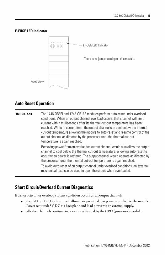
E-FUSE LED Indicator
Auto Reset Operation
Short Circuit/Overload Current DiagnosticsIf a short circuit or overload current condition occurs on an output channel:
• the E-FUSE LED indicator will illuminate provided that power is applied to the module. Power required: 5V DC via backplane and load power via an external supply.
• all other channels continue to operate as directed by the CPU (processor) module.
IMPORTANT The 1746-OB6EI and 1746-OB16E modules perform auto-reset under overload conditions. When an output channel overload occurs, that channel will limit current within milliseconds after its thermal cut-out temperature has been reached. While in current limit, the output channel can cool below the thermal cut-out temperature allowing the module to auto-reset and resume control of the output channel as directed by the processor until the thermal cut-out temperature is again reached.Removing power from an overloaded output channel would also allow the output channel to cool below the thermal cut-out temperature, allowing auto-reset to occur when power is restored. The output channel would operate as directed by the processor until the thermal cut-out temperature is again reached.To avoid auto-reset of an output channel under overload conditions, an external mechanical fuse can be used to open the circuit when overloaded.
OUTPUT
EFUSE
E-FUSE LED Indicator
There is no jumper setting on this module.
Front View
Publication 1746-IN027D-EN-P - December 2012
16 SLC 500 Digital I/O Modules
Recovery from Channel Shutdown
1. Remove the SLC 500 system power and correct the conditions causing the short circuit or overload current condition.
2. Restore the SLC 500 system power. The module automatically resets and resumes control of the output channel and associated load.
Publication 1746-IN027D-EN-P - December 2012
SLC 500 Digital I/O Modules 17
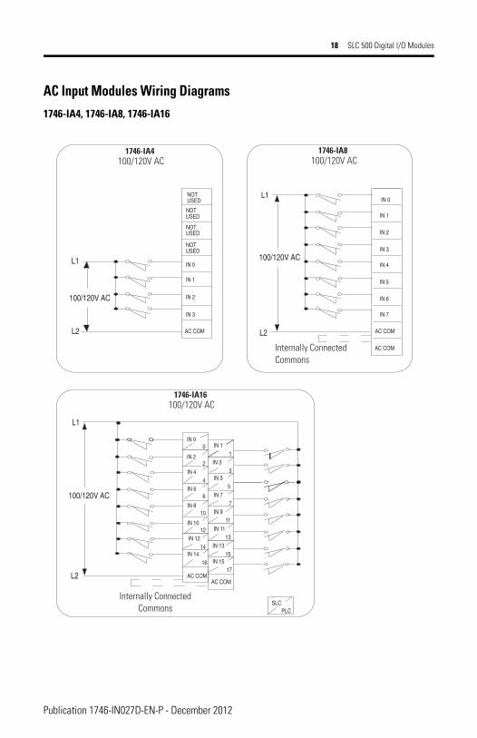
Wiring DiagramsThe wiring diagrams in these installation instructions are examples only. It is not necessary to connect an I/O device to each and every I/O module terminal.
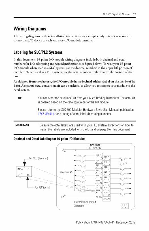
Labeling for SLC/PLC SystemsIn this document, 16-point I/O module wiring diagrams include both decimal and octal numbers for I/O addressing and wire identification (see figure below). To wire your 16-point I/O module when used in a SLC system, use the decimal numbers in the upper left portion of each box. When used in a PLC system, use the octal numbers in the lower right portion of the box. As shipped from the factory, the I/O module has a decimal address label on the inside of its door. A separate octal conversion kit can be ordered, to allow you to convert your module to the octal system.
Decimal and Octal Labeling for 16-point I/O Modules
TIP You can order the octal label kit from your Allen-Bradley Distributor. The octal kit is ordered based on the catalog number of the I/O module.
Please refer to the SLC 500 Modular Hardware Style User Manual, publication 1747-UM011, for a listing of octal label kit catalog numbers.
IMPORTANT Be sure the octal labels are used with your PLC system. Directions on how to install the labels are included with the kit and on page 6 of this document.
IN 14
16
IN 1IN 0
IN 2IN 3
IN 4IN 5
IN 6IN 7
IN 9
IN 10IN 11
IN 12IN 13
IN 14IN 15
AC COMAC COM
0 1
2
4
6
IN 8 10
12
14
16
11
13
15
17
3
5
7
L1
L2
PLCSLC
100/120V AC
1746-IA16100/120V AC
Internally Connected Commons
For PLC (octal)
For SLC (decimal)
Publication 1746-IN027D-EN-P - December 2012
18 SLC 500 Digital I/O Modules
AC Input Modules Wiring Diagrams1746-IA4, 1746-IA8, 1746-IA16
PLCSLC
IN 1IN 0
IN 2IN 3
IN 4IN 5
IN 6IN 7
IN 9
IN 10IN 11
IN 12IN 13
IN 14IN 15
AC COMAC COM
0 1
2
4
6
IN 8 10
12
14
16
11
13
15
17
3
5
7
L1
L2
100/120V AC
L1
L2
100/120V AC
IN 0
IN 1
IN 2
IN 3
IN 4
IN 5
IN 6
IN 7
AC COM
AC COM
L1
100/120V AC
NOTUSED
NOTUSED
NOTUSED
NOTUSED
IN 0
IN 1
IN 2
IN 3
AC COML2
1746-IA4100/120V AC
1746-IA8100/120V AC
Internally Connected Commons
1746-IA16100/120V AC
Internally Connected Commons
Publication 1746-IN027D-EN-P - December 2012
SLC 500 Digital I/O Modules 19
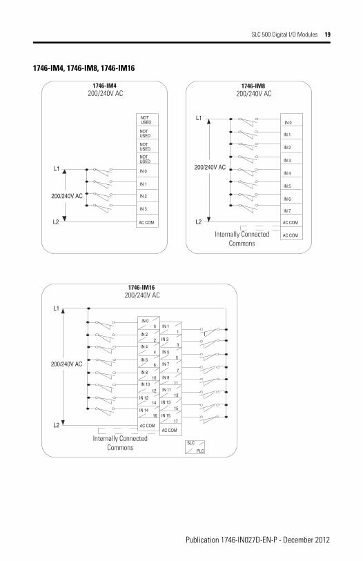
1746-IM4, 1746-IM8, 1746-IM16
IN 0
IN 1
IN 2
IN 3
IN 4
IN 5
IN 6
IN 7
AC COM
L1
L2
AC COM
200/240V AC
NOTUSED
NOTUSED
NOTUSED
NOTUSED
IN 0
IN 1
IN 2
IN 3
AC COM
L1
L2
200/240V AC
PLC
L1
L2
200/240V AC
IN 0
IN 2
IN 4
IN 6
IN 10
IN 12
IN 14
AC COM
0
2
4
6
IN 8 10
12
14
16
SLC
3
IN 5
IN 7
IN 9
IN 11
IN 13
IN 15
AC COM
11
13
15
17
5
7
IN 1 1
IN 3
1746-IM4200/240V AC
1746-IM8200/240V AC
Internally Connected Commons
1746-IM16200/240V AC
Internally Connected Commons
Publication 1746-IN027D-EN-P - December 2012
20 SLC 500 Digital I/O Modules
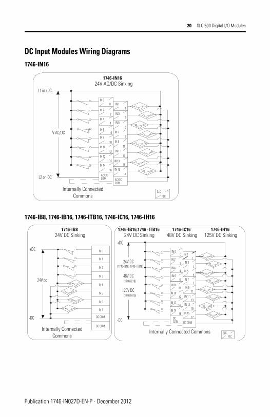
DC Input Modules Wiring Diagrams1746-IN16
1746-IB8, 1746-IB16, 1746-ITB16, 1746-IC16, 1746-IH16
PLCSLC
L1 or +DC
L2 or -DC
IN 1IN 0
IN 2IN 3
IN 4IN 5
IN 6IN 7
IN 9
IN 10IN 1 1
IN 12IN 13
IN 14IN 15
AC/DCCOM AC/DC
COM
0 1
2
4
6IN 8
10
12
14
16
11
13
15
17
3
5
7V AC/DC
1746-IN1624V AC/DC Sinking
Internally Connected Commons
-DC
IN 0
IN 1
IN 2
IN 3
IN 4
IN 5
IN 6
IN 7
+DC
-DC
DC COM
DC COM
24V dc
PLCSLC
+DC
IN 1IN 0
IN 2IN 3
IN 4IN 5
IN 6IN 7
IN 9
IN 1 1
IN 12 IN 13
IN 14IN 15
DCCOM DC COM
0
12
4
6IN 8
10
14
11
13
15
17
3 5 7
24V DC(1746-IB16, 1746- ITB16)
48V DC(1746-IC16)
125V DC(1746-IH16)
6
IN 1012
16
1746-IB824V DC Sinking
Internally Connected Commons
1746-IB16,1746 -ITB1624V DC Sinking
1746-IC1648V DC Sinking
1746-IH16125V DC Sinking
Internally Connected Commons
Publication 1746-IN027D-EN-P - December 2012

SLC 500 Digital I/O Modules 21
1746-IV8, 1746-IV16, 1746-ITV16
1746-IG16
PLCSLC
-DC
+DC
IN 1IN 0
IN 2IN 3
IN 4IN 5
IN 6IN 7
IN 9
IN 10IN 1 1
IN 12IN 13
IN 14IN 15
VDCVDC
0
1 2 4 6
IN 8 10
12
14
16
11
13
15
17
3 5
7
24V dc
IN 0
IN 1
IN 2
IN 3
IN 4
IN 5
IN 6
IN 7
VDC
-DC
+DC
VDC
24V dc
1746-IV824V DC Sourcing
Internally Connected V DC
Internally Connected V DC
1746-IV16, 1746-ITV1624V DC Sourcing
PLC
IN 0
IN 2
IN 3IN 4
IN 5IN 6
IN 7
IN 9IN 10
IN 1 1IN 12
IN 13IN 14
DC COM
0
1 2
4
6
10
12
14
16
11
13
15IN 15
17
3
5
7
+DC
-DC
SLC
+5V DC IN 8
IN 1
+5 DC
1746-IG16TTL Input (Low = True)
Publication 1746-IN027D-EN-P - December 2012
22 SLC 500 Digital I/O Modules
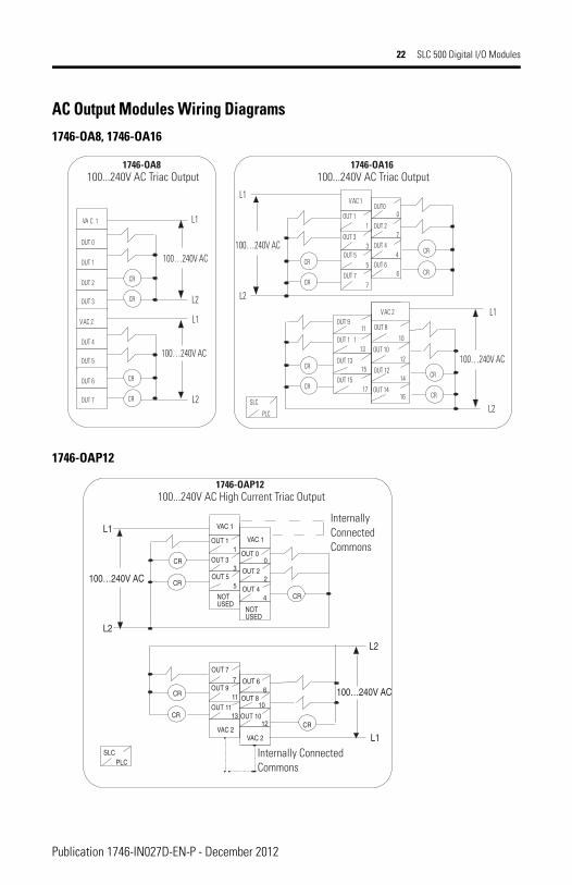
AC Output Modules Wiring Diagrams1746-OA8, 1746-OA16
1746-OAP12
100…240V AC
CR
CR
VA C 1
OUT 0
OUT 1
OUT 2
OUT 3
VAC 2
OUT 4
OUT 5
OUT 6
OUT 7 CR
CR
L2
L1
L2
L1OUT0
OUT 2
OUT 3OUT 4
OUT 5OUT 6
OUT 9OUT 8
OUT 1 1OUT 10
OUT 14
OUT 12
0
2
4
6
11
13
16
10
12
14
3
5
L1
PLC
SLCCR
CR
L2
CR
CR
CR
CR
L2
CR
CR
100…240V AC
OUT 7 7
OUT 1 1
VAC 1
100…240V AC
L1
OUT 15 17
OUT 13 15
VAC 2
100…240V AC
1746-OA8100...240V AC Triac Output
1746-OA16100...240V AC Triac Output
11
7OUT 7
OUT 2
OUT 3
OUT 4
OUT 5 2
4
3
5
L1
PLCSLC
CR
L2
CR
CR
L2
CR
100…240V AC
OUT 11
VAC 1
100…240V AC
NOTUSED
VAC 2 L1
CR
CR
NOTUSED
OUT 00
VAC 2
VAC 1
OUT 10OUT 11
1213
OUT 9OUT 8
10
OUT 66
1746-OAP12100...240V AC High Current Triac Output
Internally Connected Commons
Internally Connected Commons
Publication 1746-IN027D-EN-P - December 2012
SLC 500 Digital I/O Modules 23
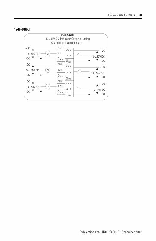
1746-OB6EI
VDC 0
OUT 0
DCCOM 0
VDC 2
OUT 2
DCCOM 2
VDC 4
OUT 4
DCCOM 4
VDC 1+DC
-DC
+DC
-DC
+DC
-DC
+DC
-DC
+DC
-DC
+DC
-DC
10…30V DC OUT 1
DCCOM 1
VDC 3
OUT 3
DCCOM 3
VDC 5
OUT 5
DCCOM 5
CR
CR
CR
1746-OB6EI10...30V DC Transistor Output-sourcing
Channel-to-channel Isolated
10…30V DC
10…30V DC
10…30V DC
10…30V DC
10…30V DC
Publication 1746-IN027D-EN-P - December 2012
24 SLC 500 Digital I/O Modules
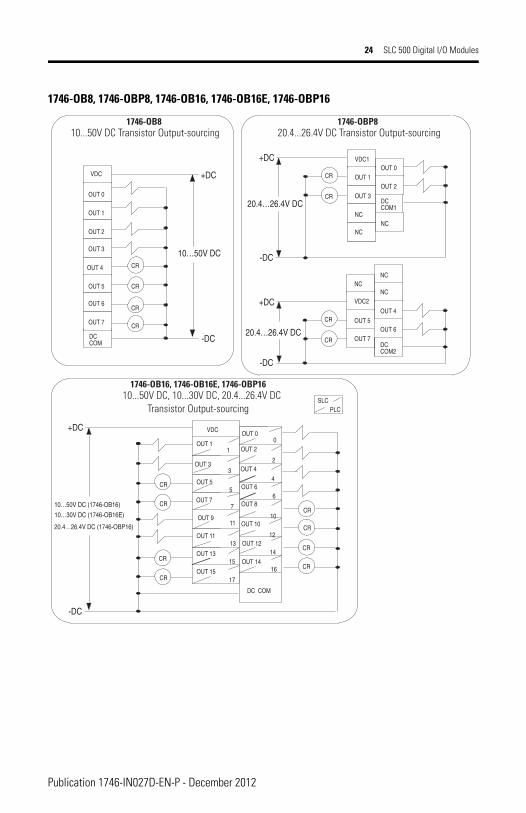
1746-OB8, 1746-OBP8, 1746-OB16, 1746-OB16E, 1746-OBP16
VDC1
OUT 1
OUT 3
NC
NC
CR
CROUT 0
OUT 2
NC
DCCOM1
-DC
+DC
20.4…26.4V DC
-DC
+DC
10…50V DC
-DC
+DC
20.4…26.4V DC
-DC
+DC
10…50V DC (1746-OB16)
10…30V DC (1746-OB16E)
20.4…26.4V DC (1746-OBP16)
VDC2
OUT 7
OUT 5
NC
CR
CR
OUT 6
OUT 4
NC
DCCOM2
NC
VDC
OUT 0
OUT 1
OUT 2
OUT 3
OUT 4
OUT 5
OUT 6
OUT 7
DCCOM
CR
CR
CR
CR
OUT 3
OUT 5
OUT 9
OUT 11
11
13
3
5
PLCSLC
CR
CR
CR
CR
OUT 7 7
OUT 1 1
VDC
OUT 15 17
OUT 13 15
CR
CR
CR
CR
OUT 0
OUT 2
OUT 4
OUT 6
OUT 8
OUT 10
OUT 14
OUT 12
0
2
4
6
16
10
12
14
DC COM
1746-OB810...50V DC Transistor Output-sourcing
1746-OBP820.4...26.4V DC Transistor Output-sourcing
1746-OB16, 1746-OB16E, 1746-OBP1610...50V DC, 10...30V DC, 20.4...26.4V DC
Transistor Output-sourcing
Publication 1746-IN027D-EN-P - December 2012
SLC 500 Digital I/O Modules 25
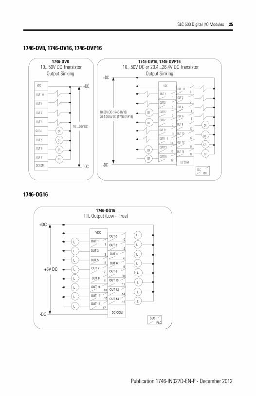
1746-OV8, 1746-OV16, 1746-OVP16
1746-OG16
VDC
OUT 0
OUT 1
OUT 2
OUT 3
OUT 4
OUT 5
OUT 6
OUT 7
DC COM -DC
+DC
CR
CR
CR
CR10…50V DC
PLCSLC
10-50V DC (1746-OV16)20.4-26.5V DC (1746-OVP16)
OUT 0
OUT 2
OUT 4
OUT 6
OUT 9
OUT 8
OUT 14
OUT 12
0
2
4
6
16
10
12
14
CR
CR
CR
CRCR
CR
CR
CR
DC COM
+DC
-DC
OUT 3
OUT 5
OUT 1 113
3
5OUT 7
7
OUT 1 1
VDC
OUT 15 17
OUT 13 15
11 OUT 10
1746-OV810...50V DC Transistor
Output Sinking
1746-OV16, 1746-OVP1610...50V DC or 20.4...26.4V DC Transistor
Output Sinking
16
OUT 0
OUT 2
OUT 3OUT 4
OUT 5OUT 6
OUT 9
OUT 8
OUT 11
OUT 10
OUT 14
OUT 12
0
2
4
6
11
13
10
12
14
3
5
PLCSLC
L
L
L
L
+5V DC OUT 7 7
OUT 1 1
VDC
OUT 15 17
OUT 13 15
L
L
L
L
DC COM
+DC
-DC
L
L
L
L
L
L
L
L
1746-OG16TTL Output (Low = True)
Publication 1746-IN027D-EN-P - December 2012
26 SLC 500 Digital I/O Modules
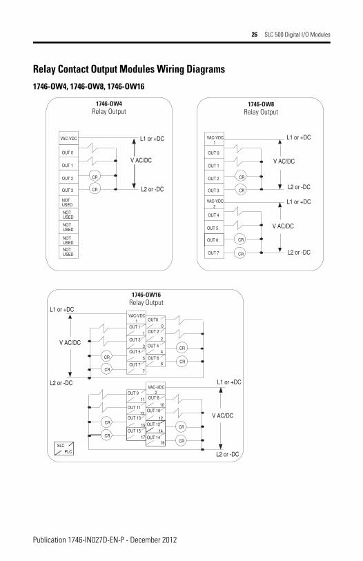
Relay Contact Output Modules Wiring Diagrams 1746-OW4, 1746-OW8, 1746-OW16
V AC/DC
CR
CR
VAC-VDC
OUT 0
OUT 1
OUT 2
OUT 3
OUT 7
L2 or -DC
L1 or +DC
CR
CR
OUT 0
OUT 1
OUT 2
OUT 3
OUT 4
OUT 5
OUT 6
OUT 7 CR
CR
NOTUSED
NOTUSED
NOTUSED
NOTUSED
NOTUSED
OUT0
OUT 2
OUT 3OUT 4
OUT 5OUT 6
OUT 9OUT 8
OUT 11OUT 10
OUT 14
OUT 12
0
2
4
6
11
13
16
10
12
14
3
5
PLCSLC
CR
CR
CR
CR
CR
CR
CR
CR
OUT 7 7
OUT 1 1
OUT 15 17
OUT 13
15
VAC-VDC1
VAC-VDC2
VAC-VDC1
VAC-VDC2
V AC/DC
L2 or -DC
L1 or +DC
V AC/DC
L2 or -DC
L1 or +DC
V AC/DC
L2 or -DC
L1 or +DC
V AC/DC
L2 or -DC
L1 or +DC
1746-OW4Relay Output
1746-OW8Relay Output
1746-OW16Relay Output
Publication 1746-IN027D-EN-P - December 2012
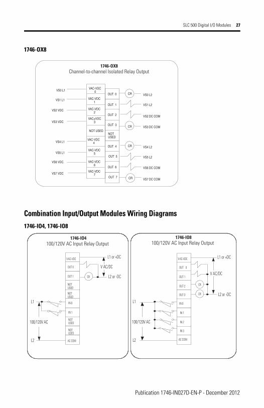
SLC 500 Digital I/O Modules 27
1746-OX8
Combination Input/Output Modules Wiring Diagrams 1746-IO4, 1746-IO8
VAC-VDC0
OUT 0
OUT 1
OUT 2
OUT 3
NOTUSED
VAC-VDC1
VAC-VDC2
VAC±VDC3
NOT USED
VAC-VDC4
VAC-VDC5
VAC-VDC6
VAC-VDC7
VS0 L1
VS1 L1
VS2 VDC
VS3 VDC
VS4 L1
VS5 L1
VS6 VDC
VS7 VDC
VS0 L2
VS1 L2
VS2 DC COM
VS3 DC COM
VS4 L2
VS5 L2
VS6 DC COM
VS7 DC COM
CR
CR
OUT 4
OUT 5
OUT 6
OUT 7
CR
CR
1746-OX8Channel-to-channel Isolated Relay Output
CR
VAC-VDC
OUT 0
OUT 1
NOTUSED
NOTUSED
OUT 7
IN 0
IN 1
NOTUSED
NOTUSED
AC COM
L1
L2
CR
CR
OUT 0
OUT 1
OUT 2
OUT 3
OUT 7
L2 or -DC
L1 or +DC
IN 0
IN 1
IN 2
IN 3
AC COM
L1
L2
100/120V AC
VAC-VDC
V AC/DCL2 or -DC
L1 or +DC
V AC/DC
100/120V AC
1746-IO4100/120V AC Input Relay Output
1746-IO8100/120V AC Input Relay Output
Publication 1746-IN027D-EN-P - December 2012
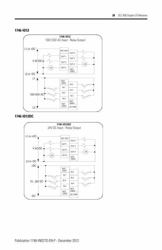
28 SLC 500 Digital I/O Modules
1746-IO12
1746-IO12DC
OUT 0
OUT 2
OUT 3OUT 4
OUT 5NOTUSED
IN 1IN 2
IN 3
IN 4
AC COM
NOTUSED
CR
CR
NOTUSED
OUT 1
NOTUSED
IN 5
VAC-VDC
IN 0
100/120V AC
L1
L2
L2 or -DC
L1 or +DC
V AC/DC
1746-IO12100/120V AC Input - Relay Output
OUT 0
OUT 2
OUT 3OUT 4
OUT 5NOTUSED
IN 1IN 2
IN 3
IN 4
DC COM
NOTUSED
CR
CR
NOTUSED
OUT 1
NOTUSED
IN 5
VAC-VDC
IN 0
-DC
10…30V DC
+DC
L2 or -DC
L1 or +DC
V AC/DC
1746-IO12DC24V DC Input - Relay Output
Publication 1746-IN027D-EN-P - December 2012
SLC 500 Digital I/O Modules 29
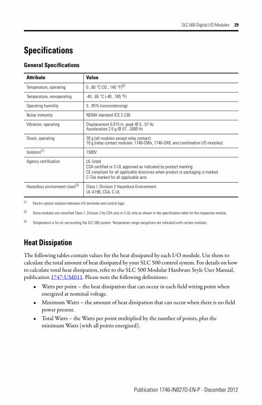
Specifications
Heat DissipationThe following tables contain values for the heat dissipated by each I/O module. Use them to calculate the total amount of heat dissipated by your SLC 500 control system. For details on how to calculate total heat dissipation, refer to the SLC 500 Modular Hardware Style User Manual, publication 1747-UM011. Please note the following definitions:
• Watts per point – the heat dissipation that can occur in each field wiring point when energized at nominal voltage.
• Minimum Watts – the amount of heat dissipation that can occur when there is no field power present.
• Total Watts – the Watts per point multiplied by the number of points, plus the minimum Watts (with all points energized).
General Specifications
Attribute Value
Temperature, operating 0...60 °C (32...140 °F)(3)
(3) Temperature is for air surrounding the SLC 500 system. Temperature range exceptions are indicated with certain modules.
Temperature, nonoperating -40...85 °C (-40...185 °F)
Operating humidity 5...95% (noncondensing)
Noise immunity NEMA standard ICS 2-230
Vibration, operating Displacement 0.015 in. peak @ 5...57 HzAcceleration 2.5 g @ 57...2000 Hz
Shock, operating 30 g (all modules except relay contact)10 g (relay contact modules: 1746-OWx, 1746-OX8, and combination I/O modules)
Isolation(1)
(1) Electro-optical isolation between I/O terminals and control logic.
1500V
Agency certification UL listedCSA certified or C-UL approved as indicated by product markingCE compliant for all applicable directives when product or packaging is markedC-Tick marked for all applicable acts
Hazardous environment class(2)
(2) Some modules are classified Class 1, Division 2 by CSA only or C-UL only as shown in the specification table for the respective module.
Class I, Division 2 Hazardous EnvironmentUL-A196, CSA, C-UL
Publication 1746-IN027D-EN-P - December 2012

30 SLC 500 Digital I/O Modules
Input Modules Heat Dissipation
Catalog Numbers Watts per Point Minimum Watts Total Watts
1747-IA4 0.27 0.175 1.30
1746-IA8 0.27 0.250 2.40
1746-IA16 0.27 0.425 4.80
1746-IB8 0.20 0.250 1.90
1746-IB16 0.20 0.425 3.60
1746-IC16 0.22 0.425 3.95
1746-IG16 0.02 0.700 1.00
1746-IH16 0.32 0.217 5.17
1746-IM4 0.35 0.175 1.60
1746-IM8 0.35 0.250 3.10
1746-IM16 0.35 0.425 6.00
1746-IN16 0.35 0.425 6.00
1746-ITB16 0.20 0.425 3.60
1746-ITV16 0.20 0.425 3.60
1746-IV8 0.20 0.250 1.90
1746-IV16 0.20 0.425 3.60
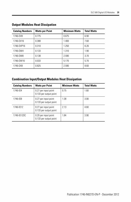
Output Modules Heat Dissipation
Catalog Numbers Watts per Point Minimum Watts Total Watts
1746-OA8 1.000 0.925 9.00
1746-OA16 0.462 1.850 9.30
1746-OAP12 1.000 1.850 10.85
1746-OB6EI 0.440 0.230 2.90
1746-OB8 0.775 0.675 6.90
1746-OB16 0.388 1.400 7.60
1746-OB16E 0.150 0.675 3.07
1746-OBP8 0.300 0.675 3.08
1746-OBP16 0.310 1.250 6.26
1746-OG16 0.033 0.900 1.50
Publication 1746-IN027D-EN-P - December 2012
SLC 500 Digital I/O Modules 31
1746-OV8 0.775 0.675 6.90
1746-OV16 0.388 1.400 7.60
1746-OVP16 0.310 1.250 6.26
1746-OW4 0.133 1.310 1.90
1746-OW8 0.138 2.590 3.70
1746-OW16 0.033 5.170 5.70
1746-OX8 0.825 2.590 8.60
Combination Input/Output Modules Heat Dissipation
Catalog Numbers Watts per Point Minimum Watts Total Watts
1746-IO4 0.27 per input point0.133 per output point
0.75 1.60
1746-IO8 0.27 per input point0.133 per output point
1.38 3.00
1746-IO12 0.27 per input point0.133 per output point
2.13 4.60
1746-IO12DC 0.20 per input point0.133 per output point
1.84 3.90
Output Modules Heat Dissipation
Catalog Numbers Watts per Point Minimum Watts Total Watts
Publication 1746-IN027D-EN-P - December 2012
32 SLC 500 Digital I/O Modules
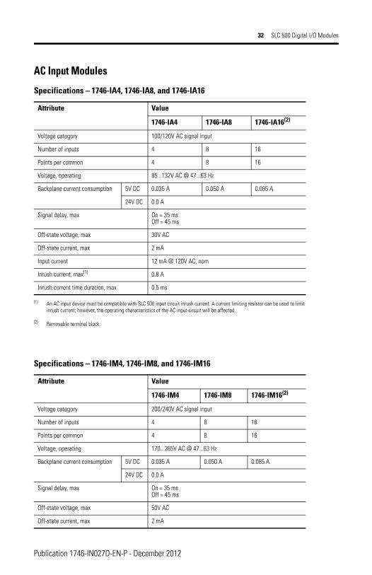
AC Input Modules
Specifications – 1746-IA4, 1746-IA8, and 1746-IA16
Attribute Value
1746-IA4 1746-IA8 1746-IA16(2)
(2) Removable terminal block.
Voltage category 100/120V AC signal input
Number of inputs 4 8 16
Points per common 4 8 16
Voltage, operating 85...132V AC @ 47...63 Hz
Backplane current consumption 5V DC 0.035 A 0.050 A 0.085 A
24V DC 0.0 A
Signal delay, max On = 35 msOff = 45 ms
Off-state voltage, max 30V AC
Off-state current, max 2 mA
Input current 12 mA @ 120V AC, nom
Inrush current, max(1)
(1) An AC input device must be compatible with SLC 500 input circuit inrush current. A current limiting resistor can be used to limit inrush current; however, the operating characteristics of the AC input-circuit will be affected.
0.8 A
Inrush current time duration, max 0.5 ms
Specifications – 1746-IM4, 1746-IM8, and 1746-IM16
Attribute Value
1746-IM4 1746-IM8 1746-IM16(2)
Voltage category 200/240V AC signal input
Number of inputs 4 8 16
Points per common 4 8 16
Voltage, operating 170...265V AC @ 47...63 Hz
Backplane current consumption 5V DC 0.035 A 0.050 A 0.085 A
24V DC 0.0 A
Signal delay, max On = 35 msOff = 45 ms
Off-state voltage, max 50V AC
Off-state current, max 2 mA
Publication 1746-IN027D-EN-P - December 2012
SLC 500 Digital I/O Modules 33
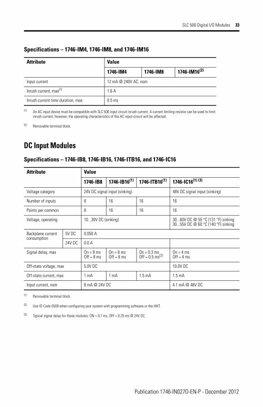
DC Input Modules
Input current 12 mA @ 240V AC, nom
Inrush current, max(1) 1.6 A
Inrush current time duration, max 0.5 ms
(1) An AC input device must be compatible with SLC 500 input circuit inrush current. A current limiting resistor can be used to limit inrush current; however, the operating characteristics of the AC input-circuit will be affected.
(2) Removable terminal block.
Specifications – 1746-IB8, 1746-IB16, 1746-ITB16, and 1746-IC16
Attribute Value
1746-IB8 1746-IB16(1)
(1) Removable terminal block.
1746-ITB16(1) 1746-IC16(1) (3)
(3) Typical signal delay for these modules: ON = 0.1 ms, OFF = 0.25 ms @ 24V DC.
Voltage category 24V DC signal input (sinking) 48V DC signal input (sinking)
Number of inputs 8 16 16 16
Points per common 8 16 16 16
Voltage, operating 10...30V DC (sinking) 30...60V DC @ 55 °C (131 °F) sinking30...55V DC @ 60 °C (140 °F) sinking
Backplane current consumption
5V DC 0.050 A
24V DC 0.0 A
Signal delay, max On = 8 msOff = 8 ms
On = 8 msOff = 8 ms
On = 0.3 msOff = 0.5 ms(2)
(2) Use ID Code 0509 when configuring your system with programming software or the HHT.
On = 4 msOff = 4 ms
Off-state voltage, max 5.0V DC 10.0V DC
Off-state current, max 1 mA 1 mA 1.5 mA 1.5 mA
Input current, nom 8 mA @ 24V DC 4.1 mA @ 48V DC
Specifications – 1746-IM4, 1746-IM8, and 1746-IM16
Attribute Value
1746-IM4 1746-IM8 1746-IM16(2)
Publication 1746-IN027D-EN-P - December 2012
34 SLC 500 Digital I/O Modules
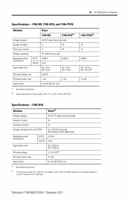
Specifications – 1746-IV8, 1746-IV16, and 1746-ITV16
Attribute Value
1746-IV8 1746-IV16(1) 1746-ITV16(1)
Voltage category 24V DC signal input (sourcing)
Number of inputs 8 16 16
Points per common 8 16 16
Voltage, operating 10...30V DC (sourcing)
Backplane current consumption
5V DC 0.050 A 0.085 A 0.085 A
24V DC 0.0 A
Signal delay, max On = 8 msOff = 8 ms
On = 8 msOff = 8 ms
On = 0.3 msOff = 0.5 ms(2)
Off-state voltage, max 5.0V DC
Off-state current, max 1 mA 1 mA 1.5 mA
Input current 8 mA @ 24V DC, nom
(1) Removable terminal block.
(2) Typical signal delay for these modules: ON = 0.1 ms, OFF = 0.25 ms @ 24V DC.
Specifications – 1746-IG16
Attribute Value(1)
(1) Removable terminal block.
Voltage category 5V DC TTL signal input (sourcing)
Number of inputs 16
Points per common 16
Voltage, operating +5V to DC COM 4.5...5.5V DC (sourcing) 50 mV peak to peak ripple (max)
Backplane current consumption
5V DC 0.140 A
24V DC 0.0 A
Signal delay, max On = 0.25 msOff = 0.50 ms
Off-state voltage 2...5.5 V DC(2)
(2) TTL inputs are inverted (-0.2...0.8V DC = low voltage = True = ON). Use a NOT instruction in your ladder program to convert to traditional True = High logic.
Off-state current, max 4.1 mA
Input current 3.7 mA @ 5V DC, nom
Publication 1746-IN027D-EN-P - December 2012
SLC 500 Digital I/O Modules 35
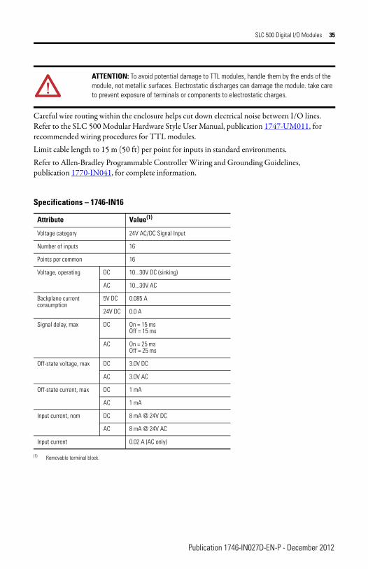
Careful wire routing within the enclosure helps cut down electrical noise between I/O lines. Refer to the SLC 500 Modular Hardware Style User Manual, publication 1747-UM011, for recommended wiring procedures for TTL modules.Limit cable length to 15 m (50 ft) per point for inputs in standard environments.Refer to Allen-Bradley Programmable Controller Wiring and Grounding Guidelines, publication 1770-IN041, for complete information.
ATTENTION: To avoid potential damage to TTL modules, handle them by the ends of the module, not metallic surfaces. Electrostatic discharges can damage the module. take care to prevent exposure of terminals or components to electrostatic charges.
Specifications – 1746-IN16
Attribute Value(1)
(1) Removable terminal block.
Voltage category 24V AC/DC Signal Input
Number of inputs 16
Points per common 16
Voltage, operating DC 10...30V DC (sinking)
AC 10...30V AC
Backplane current consumption
5V DC 0.085 A
24V DC 0.0 A
Signal delay, max DC On = 15 msOff = 15 ms
AC On = 25 msOff = 25 ms
Off-state voltage, max DC 3.0V DC
AC 3.0V AC
Off-state current, max DC 1 mA
AC 1 mA
Input current, nom DC 8 mA @ 24V DC
AC 8 mA @ 24V AC
Input current 0.02 A (AC only)
Publication 1746-IN027D-EN-P - December 2012
36 SLC 500 Digital I/O Modules
AC Output Modules
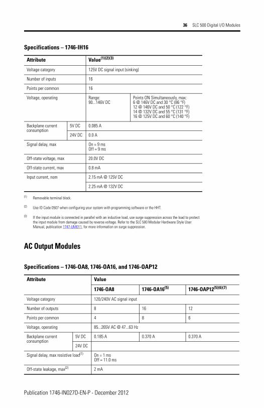
Specifications – 1746-IH16
Attribute Value(1)(2)(3)
Voltage category 125V DC signal input (sinking)
Number of inputs 16
Points per common 16
Voltage, operating Range:90...146V DC
Points ON Simultaneously, max:6 @ 146V DC and 30 °C (86 °F)12 @ 146V DC and 50 °C (122 °F)14 @ 132V DC and 55 °C (131 °F)16 @ 125V DC and 60 °C (140 °F)
Backplane current consumption
5V DC 0.085 A
24V DC 0.0 A
Signal delay, max On = 9 msOff = 9 ms
Off-state voltage, max 20.0V DC
Off-state current, max 0.8 mA
Input current, nom 2.15 mA @ 125V DC
2.25 mA @ 132V DC
(1) Removable terminal block.
(2) Use ID Code 0507 when configuring your system with programming software or the HHT.
(3) If the input module is connected in parallel with an inductive load, use surge suppression across the load to protect the input module from damage caused by reverse voltage. Refer to the SLC 500 Modular Hardware Style User Manual, publication 1747-UM011, for more information on surge suppression.
Specifications – 1746-OA8, 1746-OA16, and 1746-OAP12
Attribute Value
1746-OA8 1746-OA16(5) 1746-OAP12(5)(6)(7)
Voltage category 120/240V AC signal input
Number of outputs 8 16 12
Points per common 4 8 6
Voltage, operating 85...265V AC @ 47...63 Hz
Backplane current consumption
5V DC 0.185 A 0.370 A 0.370 A
24V DC
Signal delay, max resistive load(1) On = 1 msOff = 11.0 ms
Off-state leakage, max(2) 2 mA
Publication 1746-IN027D-EN-P - December 2012
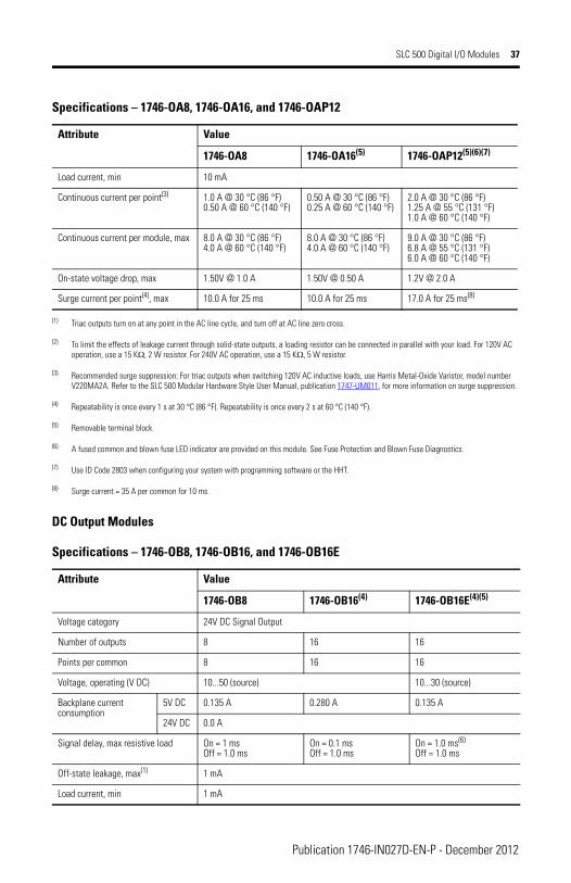
SLC 500 Digital I/O Modules 37
DC Output Modules
Load current, min 10 mA
Continuous current per point(3) 1.0 A @ 30 °C (86 °F)0.50 A @ 60 °C (140 °F)
0.50 A @ 30 °C (86 °F)0.25 A @ 60 °C (140 °F)
2.0 A @ 30 °C (86 °F)1.25 A @ 55 °C (131 °F)1.0 A @ 60 °C (140 °F)
Continuous current per module, max 8.0 A @ 30 °C (86 °F)4.0 A @ 60 °C (140 °F)
8.0 A @ 30 °C (86 °F)4.0 A @ 60 °C (140 °F)
9.0 A @ 30 °C (86 °F)6.8 A @ 55 °C (131 °F)6.0 A @ 60 °C (140 °F)
On-state voltage drop, max 1.50V @ 1.0 A 1.50V @ 0.50 A 1.2V @ 2.0 A
Surge current per point(4), max 10.0 A for 25 ms 10.0 A for 25 ms 17.0 A for 25 ms(8)
(1) Triac outputs turn on at any point in the AC line cycle, and turn off at AC line zero cross.
(2) To limit the effects of leakage current through solid-state outputs, a loading resistor can be connected in parallel with your load. For 120V AC operation, use a 15 KΩ, 2 W resistor. For 240V AC operation, use a 15 KΩ, 5 W resistor.
(3) Recommended surge suppression: For triac outputs when switching 120V AC inductive loads, use Harris Metal-Oxide Varistor, model number V220MA2A. Refer to the SLC 500 Modular Hardware Style User Manual, publication 1747-UM011, for more information on surge suppression.
(4) Repeatability is once every 1 s at 30 °C (86 °F). Repeatability is once every 2 s at 60 °C (140 °F).
(5) Removable terminal block.
(6) A fused common and blown fuse LED indicator are provided on this module. See Fuse Protection and Blown Fuse Diagnostics.
(7) Use ID Code 2803 when configuring your system with programming software or the HHT.
(8) Surge current = 35 A per common for 10 ms.
Specifications – 1746-OB8, 1746-OB16, and 1746-OB16E
Attribute Value
1746-OB8 1746-OB16(4) 1746-OB16E(4)(5)
Voltage category 24V DC Signal Output
Number of outputs 8 16 16
Points per common 8 16 16
Voltage, operating (V DC) 10...50 (source) 10...30 (source)
Backplane current consumption
5V DC 0.135 A 0.280 A 0.135 A
24V DC 0.0 A
Signal delay, max resistive load On = 1 msOff = 1.0 ms
On = 0.1 msOff = 1.0 ms
On = 1.0 ms(6)
Off = 1.0 ms
Off-state leakage, max(1) 1 mA
Load current, min 1 mA
Specifications – 1746-OA8, 1746-OA16, and 1746-OAP12
Attribute Value
1746-OA8 1746-OA16(5) 1746-OAP12(5)(6)(7)
Publication 1746-IN027D-EN-P - December 2012
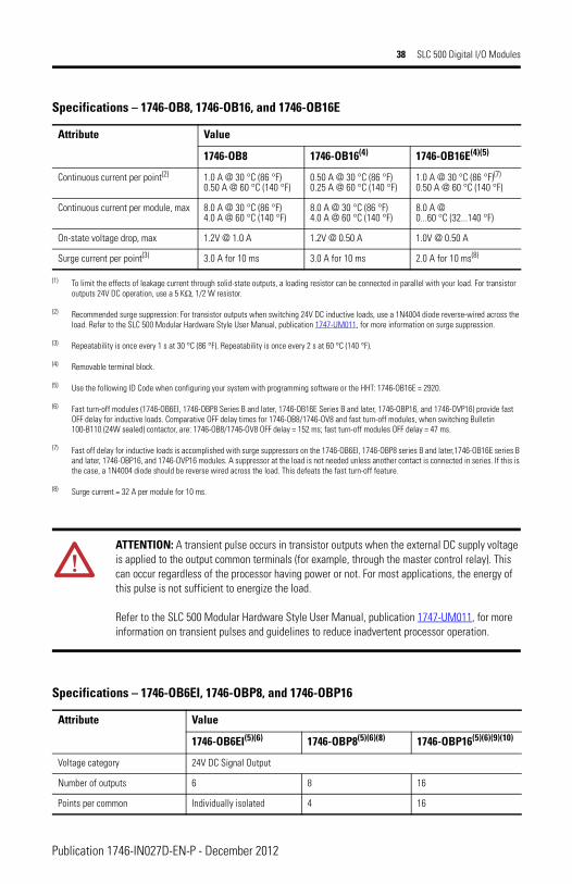
38 SLC 500 Digital I/O Modules
Continuous current per point(2) 1.0 A @ 30 °C (86 °F)0.50 A @ 60 °C (140 °F)
0.50 A @ 30 °C (86 °F)0.25 A @ 60 °C (140 °F)
1.0 A @ 30 °C (86 °F)(7)
0.50 A @ 60 °C (140 °F)
Continuous current per module, max 8.0 A @ 30 °C (86 °F)4.0 A @ 60 °C (140 °F)
8.0 A @ 30 °C (86 °F)4.0 A @ 60 °C (140 °F)
8.0 A @0...60 °C (32...140 °F)
On-state voltage drop, max 1.2V @ 1.0 A 1.2V @ 0.50 A 1.0V @ 0.50 A
Surge current per point(3) 3.0 A for 10 ms 3.0 A for 10 ms 2.0 A for 10 ms(8)
(1) To limit the effects of leakage current through solid-state outputs, a loading resistor can be connected in parallel with your load. For transistor outputs 24V DC operation, use a 5 KΩ, 1/2 W resistor.
(2) Recommended surge suppression: For transistor outputs when switching 24V DC inductive loads, use a 1N4004 diode reverse-wired across the load. Refer to the SLC 500 Modular Hardware Style User Manual, publication 1747-UM011, for more information on surge suppression.
(3) Repeatability is once every 1 s at 30 °C (86 °F). Repeatability is once every 2 s at 60 °C (140 °F).
(4) Removable terminal block.
(5) Use the following ID Code when configuring your system with programming software or the HHT: 1746-OB16E = 2920.
(6) Fast turn-off modules (1746-OB6EI, 1746-OBP8 Series B and later, 1746-OB16E Series B and later, 1746-OBP16, and 1746-OVP16) provide fast OFF delay for inductive loads. Comparative OFF delay times for 1746-OB8/1746-OV8 and fast turn-off modules, when switching Bulletin 100-B110 (24W sealed) contactor, are: 1746-OB8/1746-OV8 OFF delay = 152 ms; fast turn-off modules OFF delay = 47 ms.
(7) Fast off delay for inductive loads is accomplished with surge suppressors on the 1746-OB6EI, 1746-OBP8 series B and later,1746-OB16E series B and later, 1746-OBP16, and 1746-OVP16 modules. A suppressor at the load is not needed unless another contact is connected in series. If this is the case, a 1N4004 diode should be reverse wired across the load. This defeats the fast turn-off feature.
(8) Surge current = 32 A per module for 10 ms.
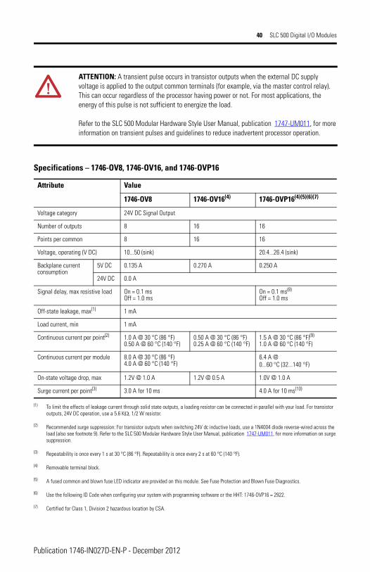
ATTENTION: A transient pulse occurs in transistor outputs when the external DC supply voltage is applied to the output common terminals (for example, through the master control relay). This can occur regardless of the processor having power or not. For most applications, the energy of this pulse is not sufficient to energize the load.
Refer to the SLC 500 Modular Hardware Style User Manual, publication 1747-UM011, for more information on transient pulses and guidelines to reduce inadvertent processor operation.
Specifications – 1746-OB6EI, 1746-OBP8, and 1746-OBP16
Attribute Value
1746-OB6EI(5)(6) 1746-OBP8(5)(6)(8) 1746-OBP16(5)(6)(9)(10)
Voltage category 24V DC Signal Output
Number of outputs 6 8 16
Points per common Individually isolated 4 16
Specifications – 1746-OB8, 1746-OB16, and 1746-OB16E
Attribute Value
1746-OB8 1746-OB16(4) 1746-OB16E(4)(5)
Publication 1746-IN027D-EN-P - December 2012
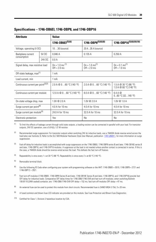
SLC 500 Digital I/O Modules 39
Voltage, operating (V DC) 10…30 (source) 20.4...26.4 (source)
Backplane current consumption
5V DC 0.046 A 0.135 A 0.250 A
24V DC 0.0 A
Signal delay, max resistive load On = 1.0 ms (7)
Off = 2.0 msOn = 1.0 ms(7)
Off = 2.0 msOn = 0.1 ms(7)
Off = 1.0 ms
Off-state leakage, max(1) 1 mA
Load current, min 1 mA
Continuous current per point(2)(3) 2.0 A @ 0…60 °C (140 °F) 2.0 A @ 0…60 °C (140 °F) 1.5 A @ 30 °C (86 °F)1.0 A @ 60 °C (140 °F)
Continuous current per module 12.0 A @ 0…60 °C (140 °F) 8.0 A @ 0…60 °C (140 °F) 6.4 A @0...60 °C (32...140 °F)
On-state voltage drop, max 1.0V @ 2.0 A 1.0V @ 2.0 A 1.0V @ 1.0 A
Surge current per point(4) 4.0 A for 10 ms 4.0 A for 10 ms 4.0 A for 10 ms
Surge current per module(4) 24.0 A for 10 ms 32.0 A for 10 ms 32.0 A for 10 ms
Electronic protection Yes No No
(1) To limit the effects of leakage current through solid state outputs, a loading resistor can be connected in parallel with your load. For transistor outputs, 24V DC operation, use a 5.6 KΩ, 1/2 W resistor.
(2) Recommended surge suppression: For transistor outputs when switching 24V dc inductive loads, use a 1N4004 diode reverse-wired across the load (also see footnote 3). Refer to the SLC 500 Modular Hardware Style User Manual, publication 1747-UM011, for more information on surge suppression.
(3) Fast off delay for inductive loads is accomplished with surge suppressors on the 1746-OB6EI, 1746-OBP8 series B and later, 1746-OB16E series B and later, 1746-OBP16, and 1746-OVP16 modules. A suppressor at the load is not needed unless another contact is connected in series. If this is the case, a 1N4004 diode should be reverse wired across the load. This defeats the fast turn-off feature.
(4) Repeatability is once every 1 s at 30 °C (86 °F). Repeatability is once every 2 s at 60 °C (140 °F).
(5) Removable terminal block.
(6) Use the following ID Code when configuring your system with programming software or the HHT: 1746-OB6EI = 2619, 1746-OBP8 = 2721 and 1746-OBP12 = 2921.
(7) Fast turn-off modules (1746-OB6EI, 1746-OBP8 Series B and later, 1746-OB16E Series B and later, 1746-OBP16, and 1746-OVP16) provide fast OFF delay for inductive loads. Comparative OFF delay times for 1746-OB8/1746-OV8 and fast turn-off modules; when switching Bulletin 100-B110 (24W sealed) contactor, are: 1746-OB8/1746-OV8 OFF delay = 152 ms; fast turn-off modules OFF delay = 47 ms.
(8) An external fuse can be used to protect this module from short circuits. Recommended fuse is SANO MQ4-3.15A, 5 x 20 mm.
(9) A fused common and blown fuse LED indicator are provided on this module. See Fuse Protection and Blown Fuse Diagnostics.
(10) Certified for Class 1, Division 2 hazardous location by CSA.
Specifications – 1746-OB6EI, 1746-OBP8, and 1746-OBP16
Attribute Value
1746-OB6EI(5)(6) 1746-OBP8(5)(6)(8) 1746-OBP16(5)(6)(9)(10)
Publication 1746-IN027D-EN-P - December 2012
40 SLC 500 Digital I/O Modules
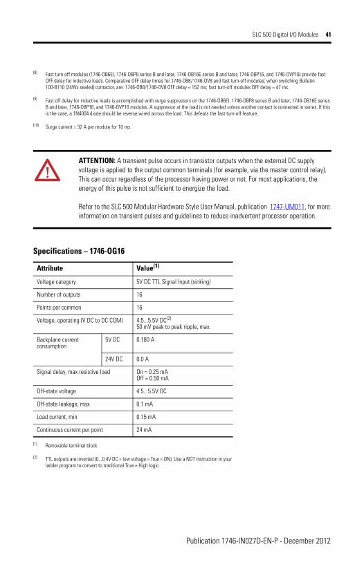
ATTENTION: A transient pulse occurs in transistor outputs when the external DC supply voltage is applied to the output common terminals (for example, via the master control relay). This can occur regardless of the processor having power or not. For most applications, the energy of this pulse is not sufficient to energize the load.
Refer to the SLC 500 Modular Hardware Style User Manual, publication 1747-UM011, for more information on transient pulses and guidelines to reduce inadvertent processor operation.
Specifications – 1746-OV8, 1746-OV16, and 1746-OVP16
Attribute Value
1746-OV8 1746-OV16(4)
(4) Removable terminal block.
1746-OVP16(4)(5)(6)(7)
(5) A fused common and blown fuse LED indicator are provided on this module. See Fuse Protection and Blown Fuse Diagnostics.
(6) Use the following ID Code when configuring your system with programming software or the HHT: 1746-OVP16 = 2922.
(7) Certified for Class 1, Division 2 hazardous location by CSA.
Voltage category 24V DC Signal Output
Number of outputs 8 16 16
Points per common 8 16 16
Voltage, operating (V DC) 10...50 (sink) 20.4...26.4 (sink)
Backplane current consumption
5V DC 0.135 A 0.270 A 0.250 A
24V DC 0.0 A
Signal delay, max resistive load On = 0.1 msOff = 1.0 ms
On = 0.1 ms(8)
Off = 1.0 ms
Off-state leakage, max(1)
(1) To limit the effects of leakage current through solid state outputs, a loading resistor can be connected in parallel with your load. For transistor outputs, 24V DC operation, use a 5.6 KΩ, 1/2 W resistor.
1 mA
Load current, min 1 mA
Continuous current per point(2)
(2) Recommended surge suppression: For transistor outputs when switching 24V dc inductive loads, use a 1N4004 diode reverse-wired across the load (also see footnote 9). Refer to the SLC 500 Modular Hardware Style User Manual, publication 1747-UM011, for more information on surge suppression.
1.0 A @ 30 °C (86 °F)0.50 A @ 60 °C (140 °F)
0.50 A @ 30 °C (86 °F)0.25 A @ 60 °C (140 °F)
1.5 A @ 30 °C (86 °F)(9)
1.0 A @ 60 °C (140 °F)
Continuous current per module 8.0 A @ 30 °C (86 °F)4.0 A @ 60 °C (140 °F)
6.4 A @0...60 °C (32...140 °F)
On-state voltage drop, max 1.2V @ 1.0 A 1.2V @ 0.5 A 1.0V @ 1.0 A
Surge current per point(3)
(3) Repeatability is once every 1 s at 30 °C (86 °F). Repeatability is once every 2 s at 60 °C (140 °F).
3.0 A for 10 ms 4.0 A for 10 ms(10)
Publication 1746-IN027D-EN-P - December 2012
SLC 500 Digital I/O Modules 41
(8) Fast turn-off modules (1746-OB6EI, 1746-OBP8 series B and later, 1746-OB16E series B and later, 1746-OBP16, and 1746-OVP16) provide fast OFF delay for inductive loads. Comparative OFF delay times for 1746-OB8/1746-OV8 and fast turn-off modules; when switching Bulletin 100-B110 (24Ws sealed) contactor, are: 1746-OB8/1746-OV8 OFF delay = 152 ms; fast turn-off modules OFF delay = 47 ms.
(9) Fast off delay for inductive loads is accomplished with surge suppressors on the 1746-OB6EI, 1746-OBP8 series B and later, 1746-OB16E series B and later, 1746-OBP16, and 1746-OVP16 modules. A suppressor at the load is not needed unless another contact is connected in series. If this is the case, a 1N4004 diode should be reverse wired across the load. This defeats the fast turn-off feature.
(10) Surge current = 32 A per module for 10 ms.
ATTENTION: A transient pulse occurs in transistor outputs when the external DC supply voltage is applied to the output common terminals (for example, via the master control relay). This can occur regardless of the processor having power or not. For most applications, the energy of this pulse is not sufficient to energize the load.
Refer to the SLC 500 Modular Hardware Style User Manual, publication 1747-UM011, for more information on transient pulses and guidelines to reduce inadvertent processor operation.
Specifications – 1746-OG16
Attribute Value(1)
(1) Removable terminal block.
Voltage category 5V DC TTL Signal Input (sinking)
Number of outputs 16
Points per common 16
Voltage, operating (V DC to DC COM) 4.5...5.5V DC(2)
50 mV peak to peak ripple, max.
(2) TTL outputs are inverted (0...0.4V DC = low voltage = True = ON). Use a NOT instruction in your ladder program to convert to traditional True = High logic.
Backplane current consumption
5V DC 0.180 A
24V DC 0.0 A
Signal delay, max resistive load On = 0.25 mAOff = 0.50 mA
Off-state voltage 4.5...5.5V DC
Off-state leakage, max 0.1 mA
Load current, min 0.15 mA
Continuous current per point 24 mA
Publication 1746-IN027D-EN-P - December 2012
42 SLC 500 Digital I/O Modules
Careful wire routing within the enclosure helps cut down electrical noise between I/O lines. Refer to the SLC 500 Modular Hardware Style User Manual, publication 1747-UM011, for recommended wiring procedures for TTL modules. Limit cable length to 3 m (10 ft) per point for outputs in standard environments.Refer to Allen-Bradley Programmable Controller Wiring and Grounding Guidelines, publication 1770-IN041, for complete information.
Relay Contact Modules
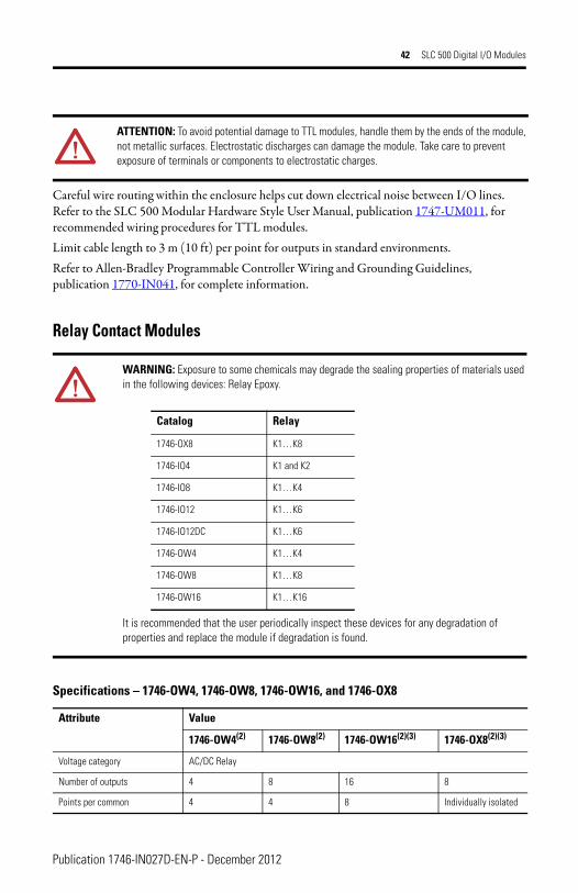
ATTENTION: To avoid potential damage to TTL modules, handle them by the ends of the module, not metallic surfaces. Electrostatic discharges can damage the module. Take care to prevent exposure of terminals or components to electrostatic charges.
WARNING: Exposure to some chemicals may degrade the sealing properties of materials used in the following devices: Relay Epoxy.
It is recommended that the user periodically inspect these devices for any degradation of properties and replace the module if degradation is found.
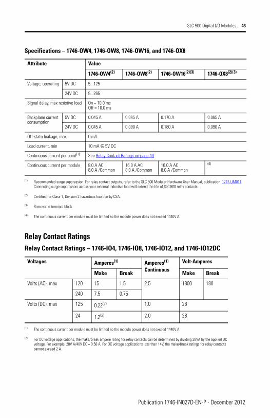
Specifications – 1746-OW4, 1746-OW8, 1746-OW16, and 1746-OX8
Attribute Value
1746-OW4(2) 1746-OW8(2) 1746-OW16(2)(3) 1746-OX8(2)(3)
Voltage category AC/DC Relay
Number of outputs 4 8 16 8
Points per common 4 4 8 Individually isolated
Catalog Relay
1746-OX8 K1…K8
1746-IO4 K1 and K2
1746-IO8 K1…K4
1746-IO12 K1…K6
1746-IO12DC K1…K6
1746-OW4 K1…K4
1746-OW8 K1…K8
1746-OW16 K1…K16
Publication 1746-IN027D-EN-P - December 2012
SLC 500 Digital I/O Modules 43
Relay Contact Ratings
Voltage, operating 5V DC 5...125
24V DC 5...265
Signal delay, max resistive load On = 10.0 msOff = 10.0 ms
Backplane current consumption
5V DC 0.045 A 0.085 A 0.170 A 0.085 A
24V DC 0.045 A 0.090 A 0.180 A 0.090 A
Off-state leakage, max 0 mA
Load current, min 10 mA @ 5V DC
Continuous current per point(1) See Relay Contact Ratings on page 43.
Continuous current per module 8.0 A AC8.0 A /Common
16.0 A AC8.0 A /Common
16.0 A AC8.0 A /Common
(4)
(1) Recommended surge suppression: For relay contact outputs, refer to the SLC 500 Modular Hardware User Manual, publication 1747-UM011. Connecting surge suppressors across your external inductive load will extend the life of SLC 500 relay contacts.
(2) Certified for Class 1, Division 2 hazardous location by CSA.
(3) Removable terminal block.
(4) The continuous current per module must be limited so the module power does not exceed 1440V A.
Relay Contact Ratings – 1746-IO4, 1746-IO8, 1746-IO12, and 1746-IO12DC
Voltages Amperes(1)
(1) The continuous current per module must be limited so the module power does not exceed 1440V A.
Amperes(1)
ContinuousVolt-Amperes
Make Break Make Break
Volts (AC), max 120 15 1.5 2.5 1800 180
240 7.5 0.75
Volts (DC), max 125 0.22(2)
(2) For DC voltage applications, the make/break ampere rating for relay contacts can be determined by dividing 28VA by the applied DC voltage. For example, 28V A/48V DC = 0.58 A. For DC voltage applications less than 14V, the make/break ratings for relay contacts cannot exceed 2 A.
1.0 28
24 1.2(2) 2.0 28
Specifications – 1746-OW4, 1746-OW8, 1746-OW16, and 1746-OX8
Attribute Value
1746-OW4(2) 1746-OW8(2) 1746-OW16(2)(3) 1746-OX8(2)(3)
Publication 1746-IN027D-EN-P - December 2012
44 SLC 500 Digital I/O Modules
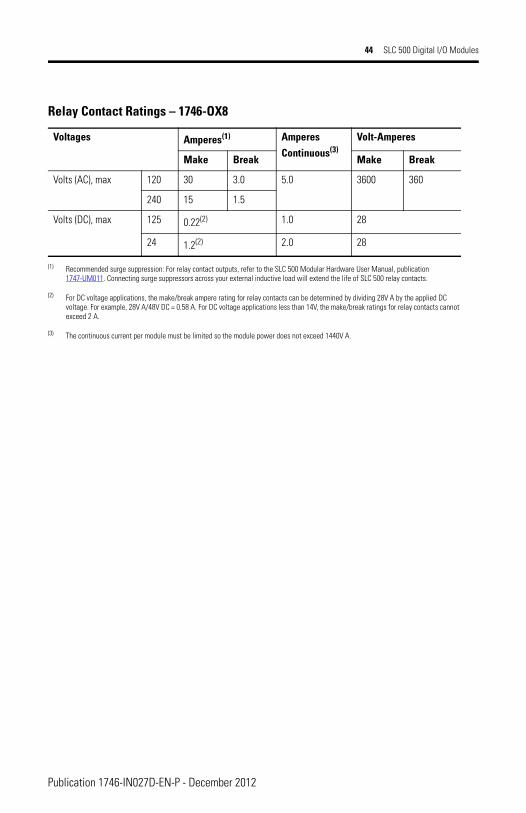
Relay Contact Ratings – 1746-OX8
Voltages Amperes(1)
(1) Recommended surge suppression: For relay contact outputs, refer to the SLC 500 Modular Hardware User Manual, publication 1747-UM011. Connecting surge suppressors across your external inductive load will extend the life of SLC 500 relay contacts.
AmperesContinuous(3)
(3) The continuous current per module must be limited so the module power does not exceed 1440V A.
Volt-Amperes
Make Break Make Break
Volts (AC), max 120 30 3.0 5.0 3600 360
240 15 1.5
Volts (DC), max 125 0.22(2)
(2) For DC voltage applications, the make/break ampere rating for relay contacts can be determined by dividing 28V A by the applied DC voltage. For example, 28V A/48V DC = 0.58 A. For DC voltage applications less than 14V, the make/break ratings for relay contacts cannot exceed 2 A.
1.0 28
24 1.2(2) 2.0 28
Publication 1746-IN027D-EN-P - December 2012
SLC 500 Digital I/O Modules 45
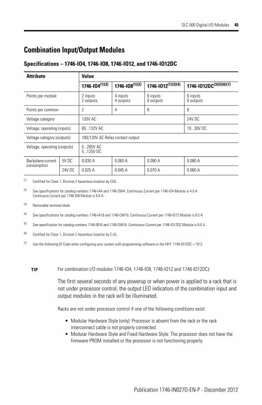
Combination Input/Output Modules
Specifications – 1746-IO4, 1746-IO8, 1746-IO12, and 1746-IO12DC
Attribute Value
1746-IO4(1)(2)
(1) Certified for Class 1, Division 2 hazardous location by CSA.
(2) See specifications for catalog numbers 1746-IA4 and 1746-OW4. Continuous Current per 1746-IO4 Module is 4.0 A. Continuous Current per 1746-IO8 Module is 8.0 A.
1746-IO8(1)(2) 1746-IO12(1)(3)(4)
(3) Removable terminal block.
(4) See specifications for catalog numbers 1746-IA16 and 1746-OW16. Continuous Current per 1746-IO12 Module is 8.0 A.
1746-IO12DC(3)(5)(6)(7)
(5) See specification for catalog numbers 1746-IB16 and 1746-OW16. Continuous Current per 1746-IO12DC Module is 8.0 A.
(6) Certified for Class 1, Division 2 hazardous location by C-UL.
(7) Use the following ID Code when configuring your system with programming software or the HHT: 1746-IO12DC = 1512.
Points per module 2 inputs2 outputs
4 inputs4 outputs
6 inputs6 outputs
6 inputs6 outputs
Points per common 2 4 6 6
Voltage category 120V AC 24V DC
Voltage, operating (inputs) 85...132V AC 10...30V DC
Voltage category (outputs) 100/120V AC Relay contact output
Voltage, operating (outputs) 5...265V AC5...125V DC
Backplane current consumption
5V DC 0.030 A 0.060 A 0.090 A 0.080 A
24V DC 0.025 A 0.045 A 0.070 A 0.060 A
TIP For combination I/O modules 1746-IO4, 1746-IO8, 1746-IO12 and 1746-IO12DC):
The first several seconds of any powerup or when power is applied to a rack that is not under processor control, the output LED indicators of the combination input and output modules in the rack will be illuminated.
Racks are not under processor control if one of the following conditions exist:
• Modular Hardware Style (only): Processor is absent from the rack or the rack interconnect cable is not properly connected.
• Modular Hardware Style and Fixed Hardware Style: The processor does not have the firmware PROM installed or the processor is not functioning properly.
Publication 1746-IN027D-EN-P - December 2012

46 SLC 500 Digital I/O Modules
Notes:
Publication 1746-IN027D-EN-P - December 2012

SLC 500 Digital I/O Modules 47
Notes:
Publication 1746-IN027D-EN-P - December 2012
Rockwell Automation Support
Rockwell Automation provides technical information on the Web to assist you in using its products. At http://support.rockwellautomation.com, you can find technical manuals, a knowledge base of FAQs, technical and application notes, sample code and links to software service packs, and a MySupport feature that you can customize to make the best use of these tools.For an additional level of technical phone support for installation, configuration and troubleshooting, we offer TechConnect support programs. For more information, contact your local distributor or Rockwell Automation representative, or visit http://support.rockwellautomation.com.Installation Assistance
If you experience a problem within the first 24 hours of installation, please review the information that's contained in this manual. You can also contact a special Customer Support number for initial help in getting your product up and running.
New Product Satisfaction Return
Rockwell Automation tests all of its products to ensure that they are fully operational when shipped from the manufacturing facility. However, if your product is not functioning and needs to be returned, follow these procedures.
Allen-Bradley, Rockwell Automation, SLC 500, and TechConnect are trademarks of Rockwell Automation, Inc.
Trademarks not belonging to Rockwell Automation are property of their respective companies.
United States 1.440.646.3434Monday – Friday, 8 a.m. – 5 p.m. EST
Outside United States Please contact your local Rockwell Automation representative for any technical support issues.
United States Contact your distributor. You must provide a Customer Support case number (call the phone number above to obtain one) to your distributor in order to complete the return process.
Outside United States Please contact your local Rockwell Automation representative for the return procedure.
Publication 1746-IN027D-EN-P - December 2012 PN-185007Supersedes Publication 1746-IN027C-EN-P - August 2008 Copyright © 2012 Rockwell Automation, Inc. All rights reserved. Printed in the U.S.A.