1746-UM026A-EN-P, SLC 500 8-Channel Analog...
74
SLC 500 8-Channel Analog Output Modules 1746-NO8I and 1746-NO8V User Manual
Transcript of 1746-UM026A-EN-P, SLC 500 8-Channel Analog...

SLC 500 8-Channel Analog Output Modules1746-NO8I and 1746-NO8V
User Manual
Important User Information Because of the variety of uses for the products described in this publication, those responsible for the application and use of these products must satisfy themselves that all necessary steps have been taken to assure that each application and use meets all performance and safety requirements, including any applicable laws, regulations, codes and standards. In no event will Rockwell Automation be responsible or liable for indirect or consequential damage resulting from the use or application of these products.
Any illustrations, charts, sample programs, and layout examples shown in this publication are intended solely for purposes of example. Since there are many variables and requirements associated with any particular installation, Rockwell Automation does not assume responsibility or liability (to include intellectual property liability) for actual use based upon the examples shown in this publication.
Allen-Bradley publication SGI-1.1, Safety Guidelines for the Application, Installation and Maintenance of Solid-State Control (available from your local Rockwell Automation office), describes some important differences between solid-state equipment and electromechanical devices that should be taken into consideration when applying products such as those described in this publication.
Reproduction of the contents of this copyrighted publication, in whole or part, without written permission of Rockwell Automation, is prohibited.
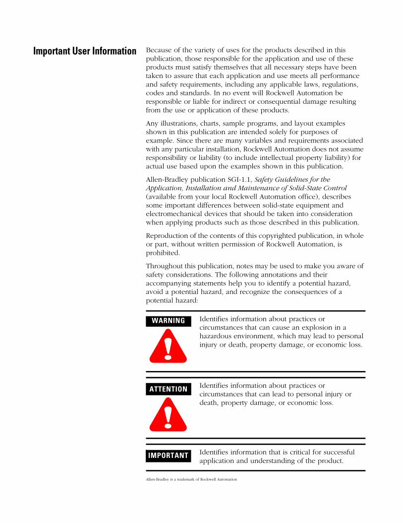
Throughout this publication, notes may be used to make you aware of safety considerations. The following annotations and their accompanying statements help you to identify a potential hazard, avoid a potential hazard, and recognize the consequences of a potential hazard:
Allen-Bradley is a trademark of Rockwell Automation
WARNING
!Identifies information about practices or circumstances that can cause an explosion in a hazardous environment, which may lead to personal injury or death, property damage, or economic loss.
ATTENTION
!Identifies information about practices or circumstances that can lead to personal injury or death, property damage, or economic loss.
IMPORTANT Identifies information that is critical for successful application and understanding of the product.
Table of ContentsPreface Who Should Use this Manual. . . . . . . . . . . . . . . . . . . . . . . P-1
Purpose of this Manual . . . . . . . . . . . . . . . . . . . . . . . . . . . P-1Common Techniques Used in this Manual . . . . . . . . . . . . . P-1Related Documentation . . . . . . . . . . . . . . . . . . . . . . . . . . . P-2
Chapter 1Overview What the Module Does . . . . . . . . . . . . . . . . . . . . . . . . . . . 1-1
General Features And Benefits . . . . . . . . . . . . . . . . . . . 1-1Hardware Features . . . . . . . . . . . . . . . . . . . . . . . . . . . . . . 1-2
Chapter 2Installation and Wiring Compliance to European Union Directives . . . . . . . . . . . . . 2-1
EMC Directive . . . . . . . . . . . . . . . . . . . . . . . . . . . . . . . 2-1Low Voltage Directive . . . . . . . . . . . . . . . . . . . . . . . . . 2-2
Hazardous Location Considerations . . . . . . . . . . . . . . . . . . 2-2Avoiding Electrostatic Damage. . . . . . . . . . . . . . . . . . . . . . 2-3Determining Power Requirements . . . . . . . . . . . . . . . . . . . 2-3Using an External 24V dc Power Supply (optional). . . . . . . 2-4
Setting The Jumper J4 . . . . . . . . . . . . . . . . . . . . . . . . . 2-4Important Notes about Using an External 24V dc Power Supply . . . . . . . . . . . . . . . . . . . 2-5
Choosing a Slot Location in the Chassis . . . . . . . . . . . . . . . 2-6Module Installation and Removal . . . . . . . . . . . . . . . . . . . . 2-7
Terminal Block Removal . . . . . . . . . . . . . . . . . . . . . . . 2-7Module Installation Procedure . . . . . . . . . . . . . . . . . . . 2-8Module Removal Procedure . . . . . . . . . . . . . . . . . . . . . 2-8
Wiring the Module . . . . . . . . . . . . . . . . . . . . . . . . . . . . . . 2-9Wiring Guidelines . . . . . . . . . . . . . . . . . . . . . . . . . . . . 2-9Wiring Procedure. . . . . . . . . . . . . . . . . . . . . . . . . . . . . 2-10Terminal Block . . . . . . . . . . . . . . . . . . . . . . . . . . . . . . 2-11
Labeling and Re-Installing the Terminal Block(if it is removed) . . . . . . . . . . . . . . . . . . . . . . . . . . . . . . . . 2-12
Chapter 3Preliminary Operating Considerations
Module ID Code . . . . . . . . . . . . . . . . . . . . . . . . . . . . . . . 3-1Class 1 and Class 3 Operation . . . . . . . . . . . . . . . . . . . . . . 3-2How the SLC Processor Communicates with the Module. . . 3-3Channel Update Time . . . . . . . . . . . . . . . . . . . . . . . . . . . . 3-3Module Response to Slot Disabling . . . . . . . . . . . . . . . . . . 3-4
i Publication 1746-UM026A-EN-P - September 2003
Table of Contents ii
Chapter 4Configuring the Module Entering the Module ID Code . . . . . . . . . . . . . . . . . . . . . . 4-1
Configuring the Module Using RSLogix 500 . . . . . . . . . . . . 4-2Configuring Each Output Channel . . . . . . . . . . . . . . . . . . . 4-6
Class 1 and Class 3 Configuration . . . . . . . . . . . . . . . . . 4-6Class 3 Configuration . . . . . . . . . . . . . . . . . . . . . . . . . . 4-6Configuration Options . . . . . . . . . . . . . . . . . . . . . . . . . 4-7
Setting the Parameter Option Values (Class 3 Only) . . . . . . 4-12Ladder Program to Configure Channel 0. . . . . . . . . . . . . . . 4-19
Chapter 5I/O Data and Status Information Output Image and Input Image Overview . . . . . . . . . . . . . 5-1
Output Image . . . . . . . . . . . . . . . . . . . . . . . . . . . . . . . 5-1Input Image. . . . . . . . . . . . . . . . . . . . . . . . . . . . . . . . . 5-3
Input Status Words . . . . . . . . . . . . . . . . . . . . . . . . . . . . . . 5-4Channel Input Status Word 1 (Class 1 and Class 3) . . . . 5-4Input Status 1 Descriptions. . . . . . . . . . . . . . . . . . . . . . 5-5Channel Input Status Word 2 (Class 3 Only) . . . . . . . . . 5-6Input Status 2 Descriptions. . . . . . . . . . . . . . . . . . . . . . 5-7
Chapter 6Module Diagnostics and Troubleshooting
Inspecting Your Module . . . . . . . . . . . . . . . . . . . . . . . . . . 6-1Disconnecting Prime Movers . . . . . . . . . . . . . . . . . . . . . . . 6-2Power-Up Diagnostics . . . . . . . . . . . . . . . . . . . . . . . . . . . . 6-2Interpreting the LED Indicators . . . . . . . . . . . . . . . . . . . . . 6-3Interpreting I/O Error Codes . . . . . . . . . . . . . . . . . . . . . . . 6-4Troubleshooting . . . . . . . . . . . . . . . . . . . . . . . . . . . . . . . . 6-5
Chapter 7Maintenance and Safety Preventative Maintenance . . . . . . . . . . . . . . . . . . . . . . . . . 7-1
Safety Considerations while Troubleshooting . . . . . . . . . . . 7-1
Appendix ASpecifications
Appendix BReplacing 1746-NO4s with 1746-NO8
Converting from 1746-NO4 to 1746-NO8 . . . . . . . . . . . . . . B-1Module ID Code . . . . . . . . . . . . . . . . . . . . . . . . . . . . . B-1Module Addressing . . . . . . . . . . . . . . . . . . . . . . . . . . . B-2Analog Conversion. . . . . . . . . . . . . . . . . . . . . . . . . . . . B-2Channel Status Words . . . . . . . . . . . . . . . . . . . . . . . . . B-3
Glossary
Index
Publication 1746-UM026A-EN-P - September 2003
Preface
Read this preface to familiarize yourself with the rest of the manual. It provides information concerning:
• who should use this manual
• the purpose of this manual
• related documentation
• conventions used in this manual
• Rockwell Automation support
Who Should Use this Manual
Use this manual if you are responsible for designing, installing, programming, or troubleshooting automation control systems that use Allen-Bradley small logic controllers.
You should have a basic understanding of SLC 500 products. You should understand electronic process control and be able to interpret the ladder logic instructions required to generate the electronic signals that control your application.
If you do not, contact your local Allen-Bradley representative for the proper training before using this product.
Purpose of this Manual This manual is a learning and reference guide for 1746-NO8 analog output module. It contains the information you need to install, wire, and configure the module. It also provides diagnostic and troubleshooting information and programming examples
Common Techniques Used in this Manual
The following conventions are used throughout this manual:
• Bulleted lists such as this one provide information, not procedural steps.
• Numbered lists provide sequential steps or hierarchical information.
• Italic type is used for emphasis.
• Text in bold type indicates words or phrases you should type
1 Publication 1746-UM026A-EN-P - September 2003

Preface 2
Related Documentation The following documents contain information that may be helpful to you as you use Allen-Bradley SLC products. If you would like a manual, you can:
• download a free electronic version from the internet:
• www.theautomationbookstore.com
• purchase a printed manual by:
– contacting your local distributor or Rockwell Automation representative
– visiting www.theautomationbookstore.com and placing your order
– calling 1.800.963.9548 (USA/Canada)
– or 001.330.725.1574 (Outside USA/Canada)
For Read this Document Document NumberAn overview of the SLC 500 family of products SLC 500 System Overview 1747-SO001
A description on how to install and use your Modular SLC 500 programmable controller system
SLC 500 Modular Hardware Style User Manual
1747-UM011
A description on how to install and use your Fixed SLC 500 programmable controller system
Installation & Operation Manual for Fixed Hardware Style Programmable Controllers
1747-6.21
A procedural and reference manual for technical personnel who use an HHT to develop control applications
Allen-Bradley Hand-Held Terminal User Manual
1747-NP002
An introduction to HHT for first-time users, containing basic concepts but focusing on simple tasks and exercises, and allowing the reader to quickly begin programming
Getting Started Guide for HHT 1747-NM009
A reference manual that contains status file data and instruction set information for the SLC 500 processors
SLC 500 Instruction Set Reference Manual
1747-RM001
Information on DF1 open protocol. DF1 Protocol and Command Set Reference Manual
1770-6.5.16
In-depth information on grounding and wiring Allen-Bradley programmable controllers
Allen-Bradley Programmable Controller Grounding and Wiring Guidelines
1770-4.1
A description of important differences between solid-state programmable controller products and hard-wired electromechanical devices
Application Considerations for Solid-State Controls
SGI-1.1
An article on wire sizes and types for grounding electrical equipment National Electrical Code - Published by the National Fire Protection Association of Boston, MA.
A complete listing of current documentation, including ordering instructions. Also indicates whether the documents are available on CD-ROM or in multi-languages.
Allen-Bradley Publication Index SD499
A glossary of industrial automation terms and abbreviations Allen-Bradley Industrial Automation Glossary
AG-7.1
Publication 1746-UM026A-EN-P - September 2003
Chapter 1
Overview
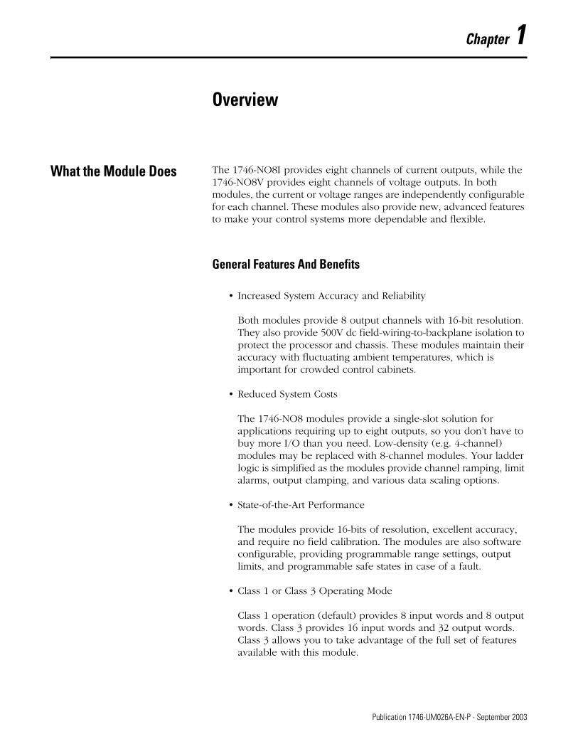
What the Module Does The 1746-NO8I provides eight channels of current outputs, while the 1746-NO8V provides eight channels of voltage outputs. In both modules, the current or voltage ranges are independently configurable for each channel. These modules also provide new, advanced features to make your control systems more dependable and flexible.
General Features And Benefits
• Increased System Accuracy and Reliability
Both modules provide 8 output channels with 16-bit resolution. They also provide 500V dc field-wiring-to-backplane isolation to protect the processor and chassis. These modules maintain their accuracy with fluctuating ambient temperatures, which is important for crowded control cabinets.
• Reduced System Costs
The 1746-NO8 modules provide a single-slot solution for applications requiring up to eight outputs, so you don’t have to buy more I/O than you need. Low-density (e.g. 4-channel) modules may be replaced with 8-channel modules. Your ladder logic is simplified as the modules provide channel ramping, limit alarms, output clamping, and various data scaling options.
• State-of-the-Art Performance
The modules provide 16-bits of resolution, excellent accuracy, and require no field calibration. The modules are also software configurable, providing programmable range settings, output limits, and programmable safe states in case of a fault.
• Class 1 or Class 3 Operating Mode
Class 1 operation (default) provides 8 input words and 8 output words. Class 3 provides 16 input words and 32 output words. Class 3 allows you to take advantage of the full set of features available with this module.
1 Publication 1746-UM026A-EN-P - September 2003
1-2 Overview
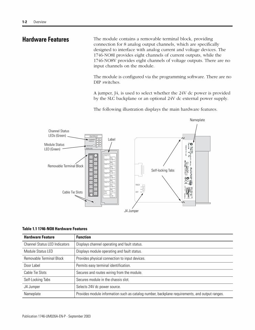
Hardware Features The module contains a removable terminal block, providing connection for 8 analog output channels, which are specifically designed to interface with analog current and voltage devices. The 1746-NO8I provides eight channels of current outputs, while the 1746-NO8V provides eight channels of voltage outputs. There are no input channels on the module.
The module is configured via the programming software. There are no DIP switches.
A jumper, J4, is used to select whether the 24V dc power is provided by the SLC backplane or an optional 24V dc external power supply.
The following illustration displays the main hardware features.
I OUT 0
CHANNELSTATUS
MODULE
ANALOG
OUTPUT
I OUT 1
I OUT 2
I OUT 3
I OUT 4
I OUT 5
I OUT 6
I OUT 7
+24VDC
ANLCOM 0
ANLCOM 1
ANLCOM 2
ANLCOM 3
ANLCOM 4
ANLCOM 5
ANLCOM 6
ANLCOM 7
DC COM
RACK
EXT
12
3
Channel Status LEDs (Green)
Module Status LED (Green)
Removable Terminal Block
Label
Cable Tie Slots
J4 Jumper
Nameplate
Self-locking Tabs
Table 1.1 1746-NO8 Hardware Features
Hardware Feature Function
Channel Status LED Indicators Displays channel operating and fault status.
Module Status LED Displays module operating and fault status.
Removable Terminal Block Provides physical connection to input devices.
Door Label Permits easy terminal identification.
Cable Tie Slots Secures and routes wiring from the module.
Self-Locking Tabs Secures module in the chassis slot.
J4 Jumper Selects 24V dc power source.
Nameplate Provides module information such as catalog number, backplane requirements, and output ranges.
Publication 1746-UM026A-EN-P - September 2003
Chapter 2
Installation and Wiring
This chapter tells you how to:
• avoid electrostatic damage
• determine the chassis power requirement for the module
• use an external 24V dc power supply (optional)
• choose a location for the module in the SLC chassis
• install and remove the module
• wire the module’s terminal block
• label and re-install the terminal block
Compliance to European Union Directives
This product is approved for installation within the European Union and EEA regions. It has been designed and tested to meet the following directives.
EMC Directive
The analog modules are tested to meet Council Directive 89/336/EEC Electromagnetic Compatibility (EMC) and the following standards, in whole or in part, documented in a technical construction file:
• EN 50081-2EMC – Generic Emission Standard, Part 2 - Industrial Environment
• EN 50082-2EMC – Generic Immunity Standard, Part 2 - Industrial Environment
This product is intended for use in an industrial environment.
1 Publication 1746-UM026A-EN-P - September 2003
2-2 Installation and Wiring
Low Voltage Directive
This product is tested to meet Council Directive 73/23/EEC Low Voltage, by applying the safety requirements of EN 61131-2 Programmable Controllers, Part 2 – Equipment Requirements and Tests.
For specific information required by EN61131-2, see the appropriate sections in this publication, as well as the following Allen-Bradley publications:
• Industrial Automation, Wiring and Grounding Guidelines for Noise Immunity, publication 1770-4.1
• Automation Systems Catalog, publication B113
Hazardous Location Considerations
This equipment is suitable for use in Class I, Division 2, Groups A, B, C, D or non-hazardous locations only. The following ATTENTION statement applies to use in hazardous locations.
ATTENTION
!EXPLOSION HAZARD
• Substitution of components may impair suitability for Class I, Division 2.
• Do not replace components or disconnect equipment unless power has been switched off.
• Do not connect or disconnect components unless power has been switched off.
• This product must be installed in an enclosure.
Publication 1746-UM026A-EN-P - September 2003
Installation and Wiring 2-3
Avoiding Electrostatic Damage
Electrostatic discharge can damage semiconductor devices inside this module if you touch backplane connector pins. Guard against electrostatic damage by observing the following precautions.
• Wear an approved wrist strap grounding device when handling the module.
• Touch a grounded object to rid yourself of electrostatic charge before handling the module.
• Handle the module from the front, away from the backplane connector. Do not touch backplane connector pins.
• Keep the module in its static-shield bag when not in use, or during shipment.
Determining Power Requirements
The module receives its power through the SLC 500 chassis backplane from the +5V dc/+24V dc chassis power supply. The +5V dc backplane supply powers the SLC circuitry, and the +24V dc backplane supply powers the module analog circuitry. The maximum current drawn by the module is shown in the table below.
Add the values shown in the table above to the requirements of all other modules in the SLC chassis to prevent overloading the chassis power supply. Refer to your controller’s User Manual for power supply loading calculations and worksheets.
ATTENTION
!Electrostatic discharge can degrade performance or cause permanent damage. Handle the module as stated below.
Table 2.1 1746-NO8 Backplane Current Consumption
Specification 1746-NO8I 1746-NO8V
Backplane Current Consumption (maximum)
120 mA at 5V dc
250 mA at 24V dc
120 mA at 5V dc
160 mA at 24V dc
Backplane Current Consumption (maximum) when Using External 24V dc Power Supply(1)
(1) The 1746-NO8I and 1746-NO8V output modules can use an external 24V dc power supply to reduce backplane loading. To use an external 24V dc power supply, you must set your module’s jumper J4 as indicated in the following section. To comply with the U.L. regulation, the external power supply must be rated N.E.C. Class 2.NOTE: The external 24V dc power supply terminal block ground connection (DC COM) is connected to the SLC power supply ground.
120 mA at 5V dc
0 mA at 24V dc
120 mA at 5V dc
0 mA at 24V dc
Publication 1746-UM026A-EN-P - September 2003
2-4 Installation and Wiring
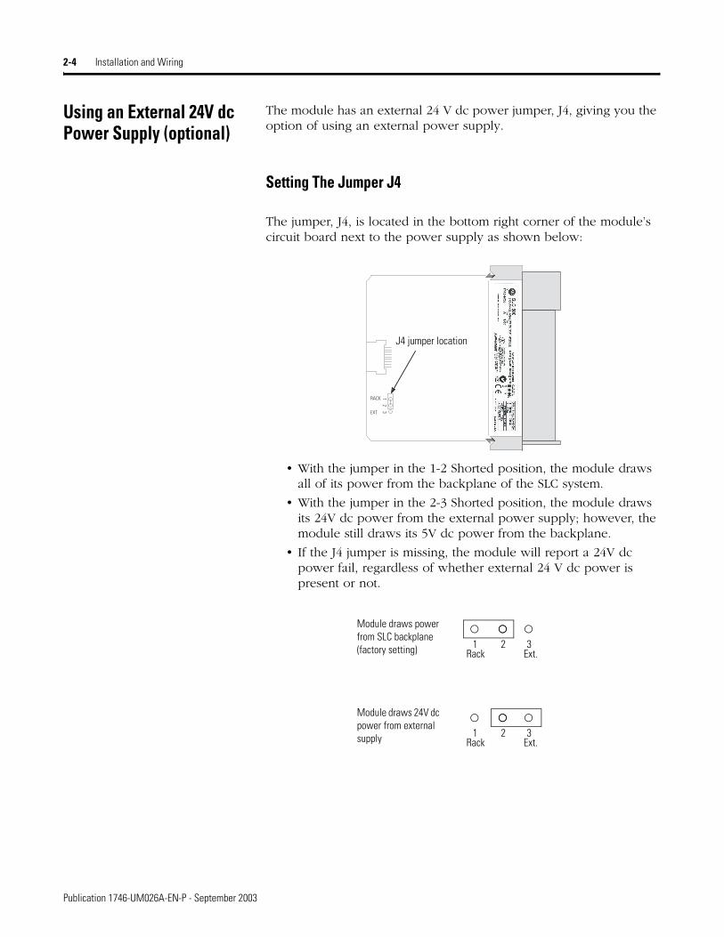
Using an External 24V dc Power Supply (optional)
The module has an external 24 V dc power jumper, J4, giving you the option of using an external power supply.
Setting The Jumper J4
The jumper, J4, is located in the bottom right corner of the module’s circuit board next to the power supply as shown below:
• With the jumper in the 1-2 Shorted position, the module draws all of its power from the backplane of the SLC system.
• With the jumper in the 2-3 Shorted position, the module draws its 24V dc power from the external power supply; however, the module still draws its 5V dc power from the backplane.
• If the J4 jumper is missing, the module will report a 24V dc power fail, regardless of whether external 24 V dc power is present or not.
RACK
EXT
12
3J4 jumper location
Rack1 2 3
Ext.
Rack1 2 3
Ext.
Module draws power from SLC backplane (factory setting)
Module draws 24V dc power from external supply
Publication 1746-UM026A-EN-P - September 2003
Installation and Wiring 2-5
Important Notes about Using an External 24V dc Power Supply
ATTENTION
!Before setting the jumper, all system power must be turned off. This includes the rack power as well as any external 24V dc power supply.
IMPORTANT If the module is configured to use an external 24V dc power supply, the supply must be turned on for the module to operate. If the external 24V dc power supply is turned off, the module’s outputs will be turned off, and the module’s processor will be reset until power is restored.
The module’s LEDs will flash the 24V Power Fail blink code. See the error blink code descriptions in Chapter 6 for more information.
IMPORTANT Do not use the 24V dc user power terminal on the chassis power supply to power the analog output module.
Publication 1746-UM026A-EN-P - September 2003
2-6 Installation and Wiring
Choosing a Slot Location in the Chassis
When selecting a slot for the module, consider the following conditions:
Table 2.2 Conditions for Locating the Analog Module
Condition Recommendation
SLC chassis slot 0 is reserved Place the module in any slot of an SLC 500 modular, or modular expansion chassis, except for the extreme left slot (slot 0) in the first chassis. This slot is reserved for the processor or adapter module.
Class 1 or Class 3 operation To use the advanced features of Class 3 operation, an SLC 5/02 or higher processor must be used, and the module must be located in the local chassis or in a remote ControlNet chassis with a 1747-ACN(R)15 adapter.
If the module is located in a remote I/O chassis with a 1747-ASB adapter, it will operate in Class 1 mode, and you must use block transfer for configuration and data retrieval.
Ambient temperature Locate the module in the chassis closest to the bottom of the enclosure (where the air is cooler) and away from modules that generate significant heat, such as 32-channel (Series C or earlier) modules. For applications using the upper limit of the operating temperature range, the module(s) should be placed in the right most slot(s) of the chassis. The specification for operating temperature is 0°C to 60°C (32°F to 140°F).
Electrical noise • Install the SLC 500 system in a properly rated (i.e., NEMA) enclosure. Make sure that the SLC 500 system is properly grounded.
• Group analog and low voltage dc modules away from ac or high-voltage dc modules, hard contact switches, relays, and ac motor drives.
• Locate analog modules away from the chassis power supply (if using a modular system).
Publication 1746-UM026A-EN-P - September 2003
Installation and Wiring 2-7
Module Installation and Removal
The printed circuit boards of the analog module must be protected from dirt, oil, moisture and other airborne contaminants. To protect these boards, the SLC 500 system must be installed in an enclosure suitable for the environment. The interior of the enclosure should be kept clean and the enclosure door should be kept closed whenever possible.
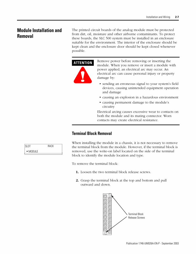
Terminal Block Removal
When installing the module in a chassis, it is not necessary to remove the terminal block from the module. However, if the terminal block is removed, use the write-on label located on the side of the terminal block to identify the module location and type.
To remove the terminal block:
1. Loosen the two terminal block release screws.
2. Grasp the terminal block at the top and bottom and pull outward and down.
ATTENTION
!Remove power before removing or inserting the module. When you remove or insert a module with power applied, an electrical arc may occur. An electrical arc can cause personal injury or property damage by:
• sending an erroneous signal to your system’s field devices, causing unintended equipment operation and damage
• causing an explosion in a hazardous environment
• causing permanent damage to the module’s circuitry
Electrical arcing causes excessive wear to contacts on both the module and its mating connector. Worn contacts may create electrical resistance.
• SLOT RACK
MODULE
Terminal Block Release Screws
Publication 1746-UM026A-EN-P - September 2003

2-8 Installation and Wiring
Module Installation Procedure
1. Read “Choosing a Slot Location in the Chassis” beginning on page 2-6.
2. Align the circuit board of the analog input module with the card guides located at the top and bottom of the chassis.
3. Slide the module into the chassis until both top and bottom retaining clips are secured. Apply firm, even pressure on the module to attach it to its backplane connector. Never force the module into the slot.
4. Cover all unused slots with the Card Slot Filler, catalog number 1746-N2.
Module Removal Procedure
1. Press the releases at the top and bottom of the module and slide the module out of the chassis slot.
2. Cover all unused slots with the Card Slot Filler, catalog number 1746-N2.
Card Guide
Top and Bottom Module Release(s)
Publication 1746-UM026A-EN-P - September 2003
Installation and Wiring 2-9
Wiring the Module To wire the terminal block, you need:
• cross-head and flat-blade screwdrivers
• Belden 8761 (shielded, twisted pair) cable or equivalent
Each terminal may hold up to two 14 gauge leads.
Wiring Guidelines
Before wiring the terminal block, take some time to plan your system:
• Ensure that the SLC 500 system is installed in a NEMA-rated enclosure and that the SLC 500 system is properly grounded.
• Ensure that the load resistance for a current output channel is less than 500 ohms.
• Ensure that the load resistance for a voltage output channel is greater than 1k ohms.
• Route the field wiring away from any other wiring and as far as possible from sources of electrical noise, such as motors, transformers, contactors, and ac devices. As a general rule, allow at least 15 cm (6 in.) of separation for every 120V of ac power.
• Use Belden cable #8761 for wiring the analog modules making sure that the drain wire and foil shield are properly earth grounded.
• Route the Belden cable separate from any high-voltage I/O wiring. Additional noise immunity can be obtained by routing the cables in grounded conduit.
• If the field wiring must cross ac or power cables, ensure that they cross at right angles.
• All analog common terminals (ANL COM) are electrically connected inside the module. ANL COM is not connected to earth ground inside the module.
ATTENTION
!POSSIBLE EQUIPMENT OPERATION
Before wiring your module, always disconnect power from the SLC 500 system and from any other source to the module.
Failure to observe this precaution can cause unintended equipment operation and damage.
Publication 1746-UM026A-EN-P - September 2003

2-10 Installation and Wiring
Wiring Procedure
To wire your module, follow these steps:
1. Determine the length of cable you need to connect a channel to its field device. Remember to include additional cable to route the shield wire and foil shield to their ground points.
2. At each end of the cable, strip some casing to expose the individual wires.
3. Trim the exposed signal wires to 50 mm (2 in) lengths. Strip about 5 mm (3/16 in.) of insulation away to expose the end of each wire.
4. At one end of the cable, twist the shield wire and foil shield together, bend them away from the cable, and apply shrink wrap.
5. At the other end of the cable, cut the drain wire and foil shield back to the cable and apply shrink wrap.
6. Connect the wires to the terminal block and field device as shown in Figure 2.1 on page 2-11. The recommended maximum terminal screw torque is 0.7 to 0.9 Nm (6 to 8 in-lb) for all terminal screws. Excessive tightening can strip the terminal screw.
7. Repeat steps 1 through 6 for each channel on your module.
Cable
(Cut foil shield and drain wire.)
Signal WireFoil ShieldDrain Wire
Signal Wire
Twist the drain wire and the foil shield together and connect to earth ground or to the chassis mounting screws.
Publication 1746-UM026A-EN-P - September 2003
Installation and Wiring 2-11
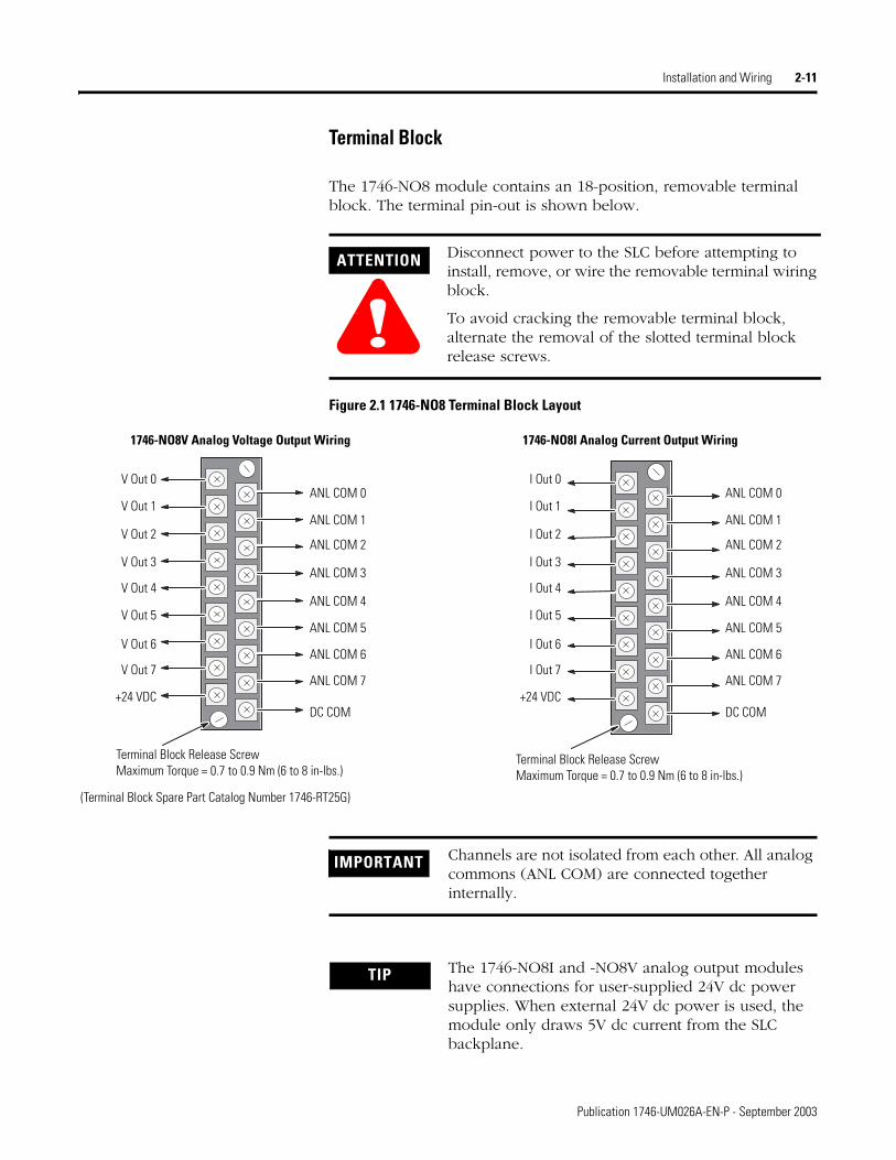
Terminal Block
The 1746-NO8 module contains an 18-position, removable terminal block. The terminal pin-out is shown below.
Figure 2.1 1746-NO8 Terminal Block Layout
ATTENTION
!Disconnect power to the SLC before attempting to install, remove, or wire the removable terminal wiring block.
To avoid cracking the removable terminal block, alternate the removal of the slotted terminal block release screws.
IMPORTANT Channels are not isolated from each other. All analog commons (ANL COM) are connected together internally.
V Out 0
V Out 1
V Out 2
V Out 3
V Out 4
V Out 5
V Out 6
V Out 7
+24 VDC
ANL COM 0
ANL COM 1
ANL COM 2
ANL COM 3
ANL COM 4
ANL COM 5
ANL COM 6
ANL COM 7
DC COM
1746-NO8V Analog Voltage Output Wiring
Terminal Block Release ScrewMaximum Torque = 0.7 to 0.9 Nm (6 to 8 in-lbs.)
I Out 0
I Out 1
I Out 2
I Out 3
I Out 4
I Out 5
I Out 6
I Out 7
+24 VDC
ANL COM 0
ANL COM 1
ANL COM 2
ANL COM 3
ANL COM 4
ANL COM 5
ANL COM 6
ANL COM 7
DC COM
1746-NO8I Analog Current Output Wiring
Terminal Block Release ScrewMaximum Torque = 0.7 to 0.9 Nm (6 to 8 in-lbs.)
(Terminal Block Spare Part Catalog Number 1746-RT25G)
TIP The 1746-NO8I and -NO8V analog output modules have connections for user-supplied 24V dc power supplies. When external 24V dc power is used, the module only draws 5V dc current from the SLC backplane.
Publication 1746-UM026A-EN-P - September 2003
2-12 Installation and Wiring
A system may malfunction due to a change in its operating environment. After installing and wiring your module, check system operation. See your controller’s User Manual for more information.
Labeling and Re-Installing the Terminal Block (if it is removed)
The supplied terminal cover has a write-on label. Using this label helps ensure that the terminal block is installed on the correct module.
Once you have wired your module and properly labeled the terminal cover, install the terminal block on your module:
1. Align the terminal block with the receptacle.
2. Insert the terminal block and press firmly at the top and bottom until it is properly seated.
3. Screw in the two retaining screws on the top and bottom of the terminal block. Maximum torque is 0.7 to 0.9 Nm (6 to 8 in-lbs.).
Publication 1746-UM026A-EN-P - September 2003
Chapter 3
Preliminary Operating Considerations
This chapter explains how the analog output module and the SLC 500 processor communicate through the module’s input and output image. It lists the preliminary setup and operation required before the module can function in a 1746 I/O system. Topics discussed include how to:
• enter the module ID code
• select the Class 1 or Class 3 interface
• interpret communication between the SLC processor and the output module
• calculate the module update time
• interpret the module response to slot disabling
Module ID Code The module identification code is a unique number encoded for each 1746 I/O module. The code defines for the processor the type of I/O or specialty module residing in a specific slot in the 1746 chassis.
Table 3.1 1746-NO8 Module ID Codes
Catalog Number ID Code
1746-NO8I Class 1 interface 3527
Class 3 interface12727
1746-NO8V Class 1 interface 3528
Class 3 interface 12728
1 Publication 1746-UM026A-EN-P - September 2003
3-2 Preliminary Operating Considerations
Class 1 and Class 3 Operation
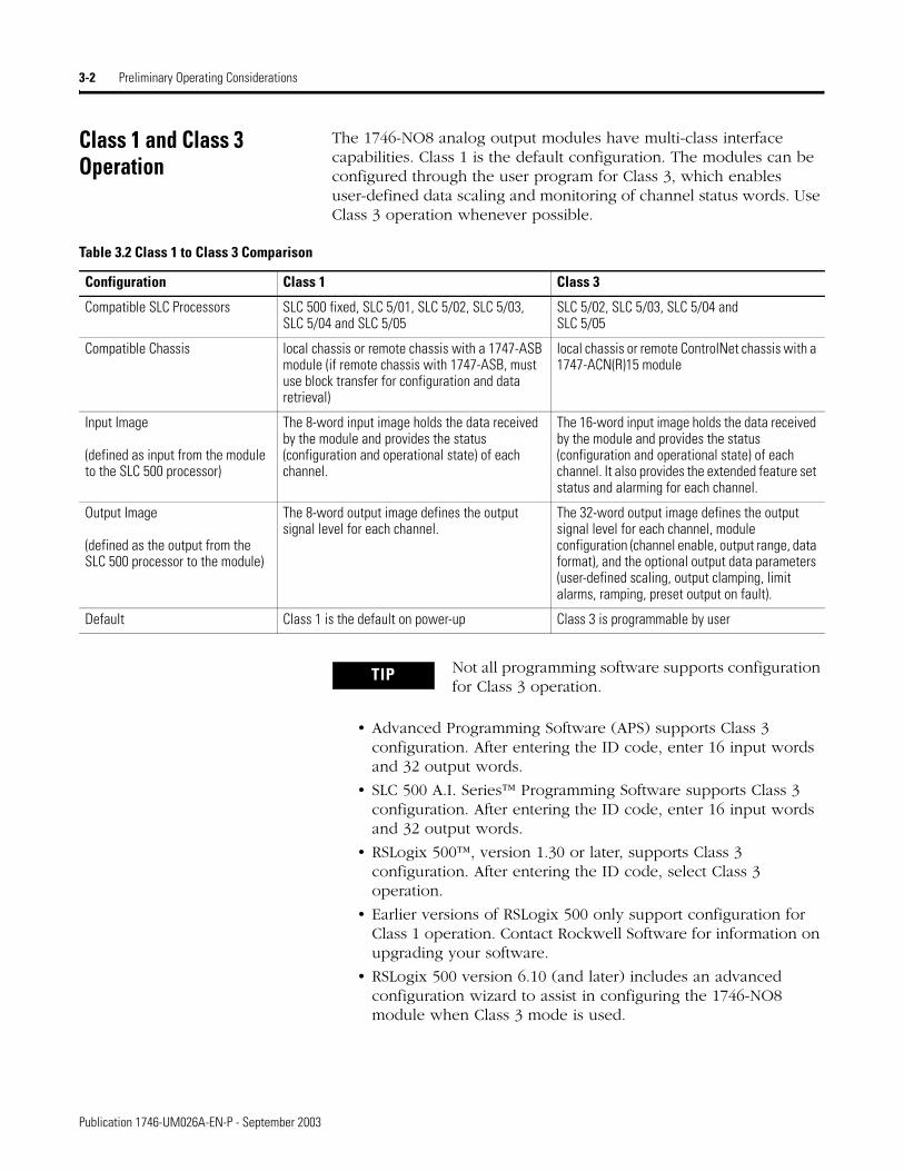
The 1746-NO8 analog output modules have multi-class interface capabilities. Class 1 is the default configuration. The modules can be configured through the user program for Class 3, which enables user-defined data scaling and monitoring of channel status words. Use Class 3 operation whenever possible.
• Advanced Programming Software (APS) supports Class 3 configuration. After entering the ID code, enter 16 input words and 32 output words.
• SLC 500 A.I. Series™ Programming Software supports Class 3 configuration. After entering the ID code, enter 16 input words and 32 output words.
• RSLogix 500™, version 1.30 or later, supports Class 3 configuration. After entering the ID code, select Class 3 operation.
• Earlier versions of RSLogix 500 only support configuration for Class 1 operation. Contact Rockwell Software for information on upgrading your software.
• RSLogix 500 version 6.10 (and later) includes an advanced configuration wizard to assist in configuring the 1746-NO8 module when Class 3 mode is used.
Table 3.2 Class 1 to Class 3 Comparison
Configuration Class 1 Class 3
Compatible SLC Processors SLC 500 fixed, SLC 5/01, SLC 5/02, SLC 5/03, SLC 5/04 and SLC 5/05
SLC 5/02, SLC 5/03, SLC 5/04 and SLC 5/05
Compatible Chassis local chassis or remote chassis with a 1747-ASB module (if remote chassis with 1747-ASB, must use block transfer for configuration and data retrieval)
local chassis or remote ControlNet chassis with a 1747-ACN(R)15 module
Input Image
(defined as input from the module to the SLC 500 processor)
The 8-word input image holds the data received by the module and provides the status (configuration and operational state) of each channel.
The 16-word input image holds the data received by the module and provides the status (configuration and operational state) of each channel. It also provides the extended feature set status and alarming for each channel.
Output Image
(defined as the output from the SLC 500 processor to the module)
The 8-word output image defines the output signal level for each channel.
The 32-word output image defines the output signal level for each channel, module configuration (channel enable, output range, data format), and the optional output data parameters (user-defined scaling, output clamping, limit alarms, ramping, preset output on fault).
Default Class 1 is the default on power-up Class 3 is programmable by user
TIP Not all programming software supports configuration for Class 3 operation.
Publication 1746-UM026A-EN-P - September 2003
Preliminary Operating Considerations 3-3
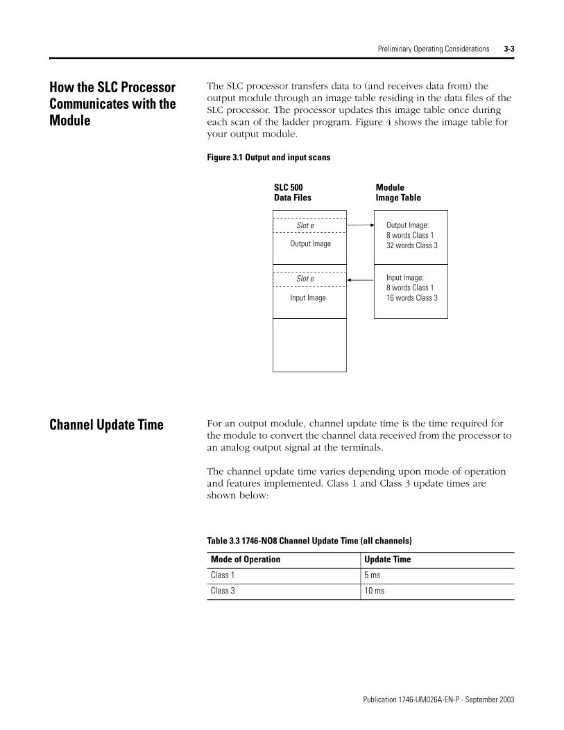
How the SLC Processor Communicates with the Module
The SLC processor transfers data to (and receives data from) the output module through an image table residing in the data files of the SLC processor. The processor updates this image table once during each scan of the ladder program. Figure 4 shows the image table for your output module.
Figure 3.1 Output and input scans
Channel Update Time For an output module, channel update time is the time required for the module to convert the channel data received from the processor to an analog output signal at the terminals.
The channel update time varies depending upon mode of operation and features implemented. Class 1 and Class 3 update times are shown below:
SLC 500 Data Files
ModuleImage Table
Slot e
Input Image
Slot e
Output Image
Output Image:8 words Class 132 words Class 3
Input Image:8 words Class 116 words Class 3
Table 3.3 1746-NO8 Channel Update Time (all channels)
Mode of Operation Update Time
Class 1 5 ms
Class 3 10 ms
Publication 1746-UM026A-EN-P - September 2003
3-4 Preliminary Operating Considerations
Module Response to Slot Disabling
By writing to the status file in the modular SLC processor, you can disable any chassis slot. Refer to the SLC 500 Instruction Set Reference Manual, publication 1747-RM001, for the slot disable/enable procedure.
When you disable an output module’s slot, the module holds its outputs in their last state in Class 1 mode. When you re-enable the output module’s slot, the data that is in the processor image table is converted to an analog output signal during the next program scan. Slot disabling only affects enabled channels. In Class 3 mode the output will go to its fault state, as configured by the user, when the slot is disabled. See Fault Options (configuration bits 12 and 13) on page 4-10 for more information on output behavior under fault conditions.
ATTENTION
!POSSIBLE EQUIPMENT OPERATION
Always understand the implications of disabling a module before using the slot disable feature.
Failure to observe this precaution can cause unintended equipment operation leading to property damage or personal injury.
Publication 1746-UM026A-EN-P - September 2003

Chapter 4
Configuring the Module
Read this chapter to:
• enter the output module’s ID code
• configure the module using the RSLogix 500 wizard
• configure the module using output words (includes detailed description of all configuration options and examples)
• set the optional features (user scaling, clamping, limit alarm, ramping/rate limit, and preset fault value)
• review an example ladder program to configure Channel 0
To configure the module, you need:
• programming equipment
• RSLogix 500 programming software
Entering the Module ID Code
Before using the module, you must configure the chassis slot your module is in by entering the module’s ID code in RSLogix 500.
When using RSLogix 500, version 6.10 or higher, simply select your module from the list of modules on the system I/O configuration display to automatically enter the ID code.
With earlier versions of RSLogix 500, you must manually enter the ID code. To enter your module’s ID code, select “other” from the list of modules on the system I/O configuration display, and enter your module’s ID code at the prompt. The module ID code for your module is:
If you perform the “READ IO CONFIG” option in RSLogix 500 programming software, version 6.10 or higher, the 1746-NO8 module will automatically be configured in Class 3 mode. With earlier versions of RSLogix 500, the module will be configured in Class 1 mode and displayed with its Class 1 module ID code.
Table 4.1 1746-NO8 Module ID Codes
Catalog Number Module ID Code
1746-NO8I 3527 Class 1 Mode (8 inputs / 8 outputs)12727 Class 3 Mode (16 inputs, 32 outputs)
1746-NO8V 3528 Class 1 Mode (8 inputs / 8 outputs)12728 Class 3 Mode (16 inputs / 32 outputs)
1 Publication 1746-UM026A-EN-P - September 2003
4-2 Configuring the Module
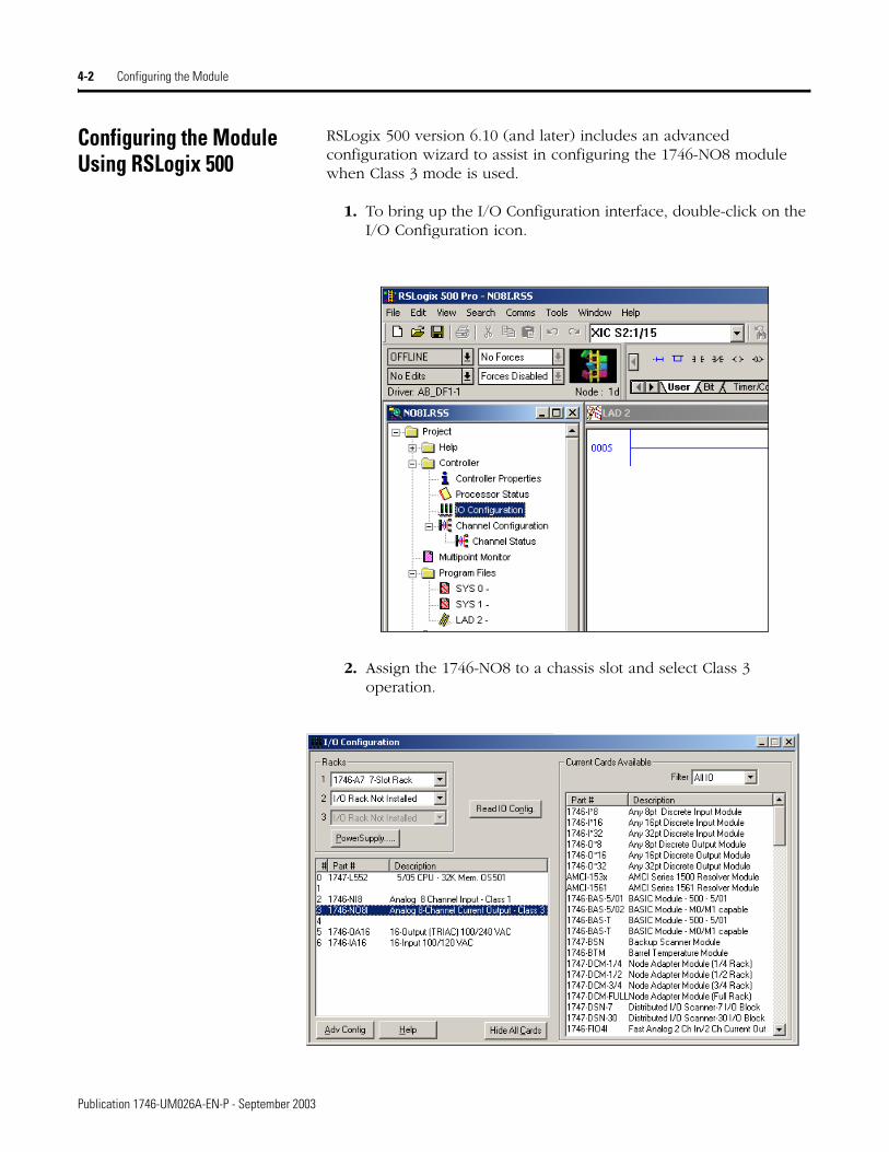
Configuring the Module Using RSLogix 500
RSLogix 500 version 6.10 (and later) includes an advanced configuration wizard to assist in configuring the 1746-NO8 module when Class 3 mode is used.
1. To bring up the I/O Configuration interface, double-click on the I/O Configuration icon.
2. Assign the 1746-NO8 to a chassis slot and select Class 3 operation.
Publication 1746-UM026A-EN-P - September 2003
Configuring the Module 4-3
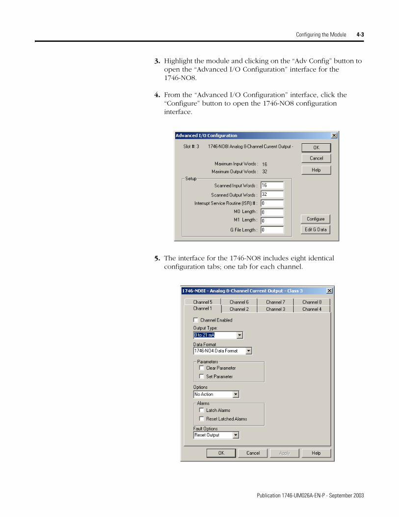
3. Highlight the module and clicking on the “Adv Config” button to open the “Advanced I/O Configuration” interface for the 1746-NO8.
4. From the “Advanced I/O Configuration” interface, click the “Configure” button to open the 1746-NO8 configuration interface.
5. The interface for the 1746-NO8 includes eight identical configuration tabs; one tab for each channel.
Publication 1746-UM026A-EN-P - September 2003

4-4 Configuring the Module
6. Check boxes and pull-downs allow for complete configuration for each channel. The pull-downs provide the following configuration options:
a. The “Channel Enabled” check box controls bit 0 of the channel configuration word.
b. The “Output Type” pull-down allows configuration of the output range (bits 1 and 2 of the channel configuration word), dependent upon the module being used.
1746-NO8I Current Output Type:0 to 21 mA4 to 20 mA0 to 20 mA
1746-NO8V Voltage Output Type:+10V dc1 to 5V dc0 to 5V dc0 to 10V dc
c. The “Clear Parameter” and “Set Parameter” check boxes correspond to bits 7 and 8 of the channel configuration word. A configuration error will occur if both are set.
Publication 1746-UM026A-EN-P - September 2003
Configuring the Module 4-5
d. The “Options” pull-down allows selection of the data format (bits 4 to 6 of the channel configuration word):
Options:1746-NO4 Data FormatEngineering UnitsScaled for PIDProportional CountsUser-defined
e. “Latch Alarms” and “Reset Latched Alarms” check boxes allow channel configuration word bits 14 and 15 to be configured.
f. The “Fault Options” pull-down allows channel configuration fault options to be selected (bits 12 and 13 of the channel configuration word).
Fault Options:Reset OutputHold OutputPreset Output
Refer to the remaining sections of this chapter for a full description of the available configuration selections.
Publication 1746-UM026A-EN-P - September 2003
4-6 Configuring the Module
Configuring Each Output Channel
Class 1 and Class 3 Configuration
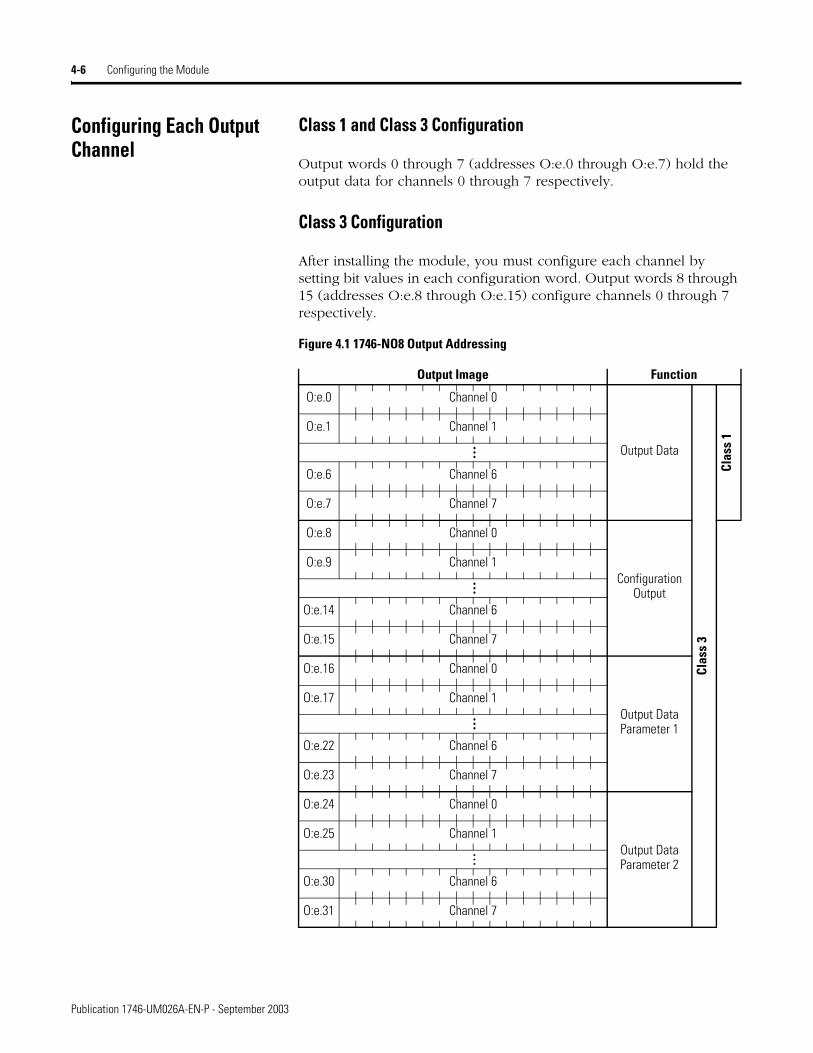
Output words 0 through 7 (addresses O:e.0 through O:e.7) hold the output data for channels 0 through 7 respectively.
Class 3 Configuration
After installing the module, you must configure each channel by setting bit values in each configuration word. Output words 8 through 15 (addresses O:e.8 through O:e.15) configure channels 0 through 7 respectively.
Figure 4.1 1746-NO8 Output Addressing
Output Image Function
Output Data
Clas
s 3
Clas
s 1
O:e.0 Channel 0
O:e.1 Channel 1
…O:e.6 Channel 6
O:e.7 Channel 7
Configuration Output
O:e.8 Channel 0
O:e.9 Channel 1
…
O:e.14 Channel 6
O:e.15 Channel 7
Output Data Parameter 1
O:e.16 Channel 0
O:e.17 Channel 1
…
O:e.22 Channel 6
O:e.23 Channel 7
Output Data Parameter 2
O:e.24 Channel 0
O:e.25 Channel 1
…
O:e.30 Channel 6
O:e.31 Channel 7
Publication 1746-UM026A-EN-P - September 2003
Configuring the Module 4-7
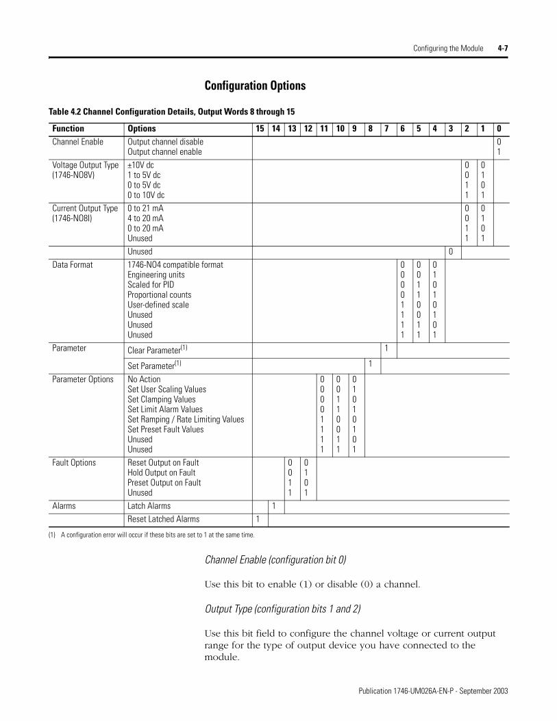
Configuration Options
Channel Enable (configuration bit 0)
Use this bit to enable (1) or disable (0) a channel.
Output Type (configuration bits 1 and 2)
Use this bit field to configure the channel voltage or current output range for the type of output device you have connected to the module.
Table 4.2 Channel Configuration Details, Output Words 8 through 15
Function Options 15 14 13 12 11 10 9 8 7 6 5 4 3 2 1 0Channel Enable Output channel disable
Output channel enable01
Voltage Output Type(1746-NO8V)
±10V dc1 to 5V dc0 to 5V dc0 to 10V dc
0011
0101
Current Output Type(1746-NO8I)
0 to 21 mA4 to 20 mA0 to 20 mAUnused
0011
0101
Unused 0Data Format 1746-NO4 compatible format
Engineering unitsScaled for PIDProportional countsUser-defined scaleUnusedUnusedUnused
00001111
00110011
01010101
Parameter Clear Parameter(1) 1
Set Parameter(1) 1
Parameter Options No ActionSet User Scaling ValuesSet Clamping ValuesSet Limit Alarm ValuesSet Ramping / Rate Limiting ValuesSet Preset Fault ValuesUnusedUnused
00001111
00110011
01010101
Fault Options Reset Output on FaultHold Output on FaultPreset Output on FaultUnused
0011
0101
Alarms Latch Alarms 1Reset Latched Alarms 1
(1) A configuration error will occur if these bits are set to 1 at the same time.
Publication 1746-UM026A-EN-P - September 2003
4-8 Configuring the Module
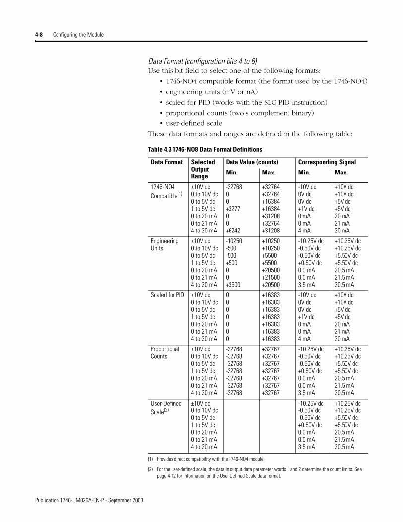
Data Format (configuration bits 4 to 6)Use this bit field to select one of the following formats:
• 1746-NO4 compatible format (the format used by the 1746-NO4)
• engineering units (mV or nA)
• scaled for PID (works with the SLC PID instruction)
• proportional counts (two’s complement binary)
• user-defined scale
These data formats and ranges are defined in the following table:
Table 4.3 1746-NO8 Data Format Definitions
Data Format Selected Output Range
Data Value (counts) Corresponding Signal
Min. Max. Min. Max.
1746-NO4Compatible(1)
(1) Provides direct compatibility with the 1746-NO4 module.
±10V dc0 to 10V dc0 to 5V dc1 to 5V dc0 to 20 mA0 to 21 mA4 to 20 mA
-3276800+327700+6242
+32764+32764+16384+16384+31208+32764+31208
-10V dc0V dc0V dc+1V dc0 mA0 mA4 mA
+10V dc+10V dc+5V dc+5V dc20 mA21 mA20 mA
Engineering Units
±10V dc0 to 10V dc0 to 5V dc1 to 5V dc0 to 20 mA0 to 21 mA4 to 20 mA
-10250-500-500+50000+3500
+10250+10250+5500+5500+20500+21500+20500
-10.25V dc-0.50V dc-0.50V dc+0.50V dc0.0 mA0.0 mA3.5 mA
+10.25V dc+10.25V dc+5.50V dc+5.50V dc20.5 mA21.5 mA20.5 mA
Scaled for PID ±10V dc0 to 10V dc0 to 5V dc1 to 5V dc0 to 20 mA0 to 21 mA4 to 20 mA
0000000
+16383+16383+16383+16383+16383+16383+16383
-10V dc0V dc0V dc+1V dc0 mA0 mA4 mA
+10V dc+10V dc+5V dc+5V dc20 mA21 mA20 mA
Proportional Counts
±10V dc0 to 10V dc0 to 5V dc1 to 5V dc0 to 20 mA0 to 21 mA4 to 20 mA
-32768-32768-32768-32768-32768-32768-32768
+32767+32767+32767+32767+32767+32767+32767
-10.25V dc-0.50V dc-0.50V dc+0.50V dc0.0 mA0.0 mA3.5 mA
+10.25V dc+10.25V dc+5.50V dc+5.50V dc20.5 mA21.5 mA20.5 mA
User-Defined Scale(2)
(2) For the user-defined scale, the data in output data parameter words 1 and 2 determine the count limits. See page 4-12 for information on the User-Defined Scale data format.
±10V dc0 to 10V dc0 to 5V dc1 to 5V dc0 to 20 mA0 to 21 mA4 to 20 mA
-10.25V dc-0.50V dc-0.50V dc+0.50V dc0.0 mA0.0 mA3.5 mA
+10.25V dc+10.25V dc+5.50V dc+5.50V dc20.5 mA21.5 mA20.5 mA
Publication 1746-UM026A-EN-P - September 2003
Configuring the Module 4-9
Parameter Set or Clear (configuration bits 7 and 8)
These bits are used to load the values from Data Parameters 1 and 2 into the corresponding feature. Setting these values also enables most features. If bit 7 is set (1), then the Data Parameter is cleared. If bit 8 is set (1), the Data Parameter is set for the feature. A configuration error occurs if both are set to 1 at the same time.
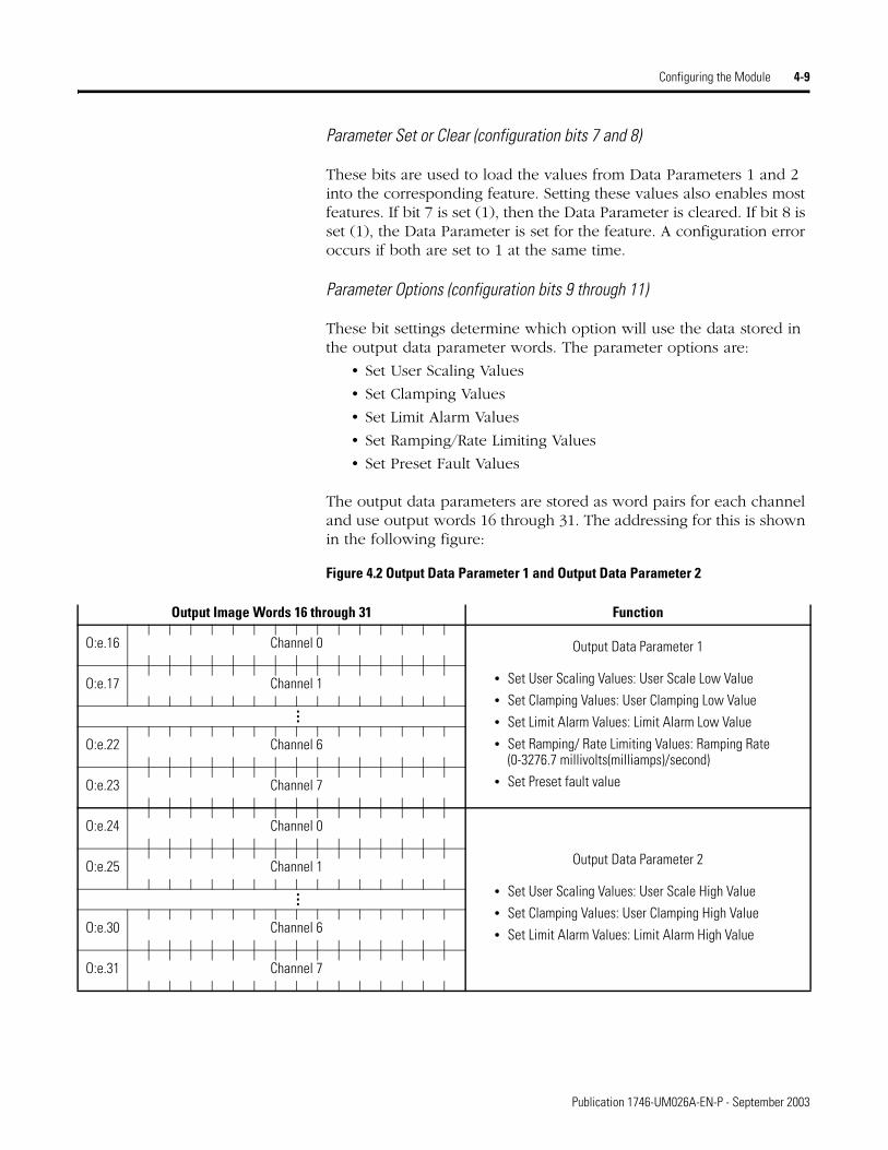
Parameter Options (configuration bits 9 through 11)
These bit settings determine which option will use the data stored in the output data parameter words. The parameter options are:
• Set User Scaling Values
• Set Clamping Values
• Set Limit Alarm Values
• Set Ramping/Rate Limiting Values
• Set Preset Fault Values
The output data parameters are stored as word pairs for each channel and use output words 16 through 31. The addressing for this is shown in the following figure:
Figure 4.2 Output Data Parameter 1 and Output Data Parameter 2
Output Image Words 16 through 31 Function
Output Data Parameter 1
• Set User Scaling Values: User Scale Low Value
• Set Clamping Values: User Clamping Low Value
• Set Limit Alarm Values: Limit Alarm Low Value
• Set Ramping/ Rate Limiting Values: Ramping Rate (0-3276.7 millivolts(milliamps)/second)
• Set Preset fault value
O:e.16 Channel 0
O:e.17 Channel 1
…
O:e.22 Channel 6
O:e.23 Channel 7
Output Data Parameter 2
• Set User Scaling Values: User Scale High Value
• Set Clamping Values: User Clamping High Value
• Set Limit Alarm Values: Limit Alarm High Value
O:e.24 Channel 0
O:e.25 Channel 1
…
O:e.30 Channel 6
O:e.31 Channel 7
Publication 1746-UM026A-EN-P - September 2003

4-10 Configuring the Module
Changing the output data format or range (bits 1 to 6 of the channel configuration word) will clear or disable user-scaling, clamping, limit alarms, ramping/rate limiting and preset fault values. Similarly, if format or range is changed, you must reconfigure the values for each of these features.
See Setting the Parameter Option Values (Class 3 Only) on page 4-12 for more details about the setting these options.
Fault Options (configuration bits 12 and 13)
This setting allows you to define the output state when a fault condition occurs. The output may be set to:
• reset output on fault (go to 0V or 0 mA)
• hold current value on fault
• go to a preset value on fault
In Class 1 operation, the output will be set to the reset value when a fault condition occurs. One exception for Class 1 is if the module’s chassis slot is disabled. Then the output will hold it’s current value.
IMPORTANT The values in output word pairs 16 through 31 apply to each individual channel. If you want to use any of these features, you must set each channel’s output word pair.
Fault Occurs
Go to Preset
Hold Current Value
Go to Reset Value
-10V
-5V
0V
2V
10V
TIP If a channel is configured to “preset output on fault” (bit 12 = 0 and bit 13 = 1) and no preset fault value was previously set, then the output will go to the reset value (0V or 0 mA) when a fault condition occurs.
TIP It is recommended that “reset output on fault” is set when a channel is disabled.
Publication 1746-UM026A-EN-P - September 2003
Configuring the Module 4-11
Fault conditions are listed below:
• CPU Fault
• Rack power goes away while the external 24V power remains
• CPU goes out of run mode
• The modules chassis slot is disabled
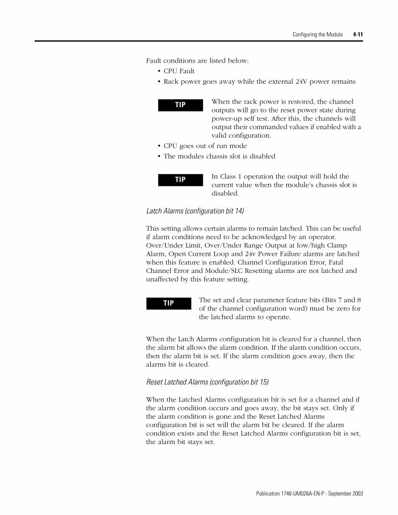
Latch Alarms (configuration bit 14)
This setting allows certain alarms to remain latched. This can be useful if alarm conditions need to be acknowledged by an operator. Over/Under Limit, Over/Under Range Output at low/high Clamp Alarm, Open Current Loop and 24v Power Failure alarms are latched when this feature is enabled. Channel Configuration Error, Fatal Channel Error and Module/SLC Resetting alarms are not latched and unaffected by this feature setting.
When the Latch Alarms configuration bit is cleared for a channel, then the alarm bit allows the alarm condition. If the alarm condition occurs, then the alarm bit is set. If the alarm condition goes away, then the alarms bit is cleared.
Reset Latched Alarms (configuration bit 15)
When the Latched Alarms configuration bit is set for a channel and if the alarm condition occurs and goes away, the bit stays set. Only if the alarm condition is gone and the Reset Latched Alarms configuration bit is set will the alarm bit be cleared. If the alarm condition exists and the Reset Latched Alarms configuration bit is set, the alarm bit stays set.
TIP When the rack power is restored, the channel outputs will go to the reset power state during power-up self test. After this, the channels will output their commanded values if enabled with a valid configuration.
TIP In Class 1 operation the output will hold the current value when the module’s chassis slot is disabled.
TIP The set and clear parameter feature bits (Bits 7 and 8 of the channel configuration word) must be zero for the latched alarms to operate.
Publication 1746-UM026A-EN-P - September 2003

4-12 Configuring the Module
Setting the Parameter Option Values (Class 3 Only)
User-Defined Scale
For special applications, the module allows definition of a custom data format. This “user-defined scale” is very similar to the “proportional counts” data format, except that instead of converting the output data to an output signal using a previously defined scale (-32,768 to 32,767), the module converts the output data using a scale defined by “low limit of scale” (output word 16) and “high limit of scale” (output word 24) for Channel 0.
You select the data format for each channel using that channel’s configuration bits, described in the previous subsection, Data Format (configuration bits 4 to 6) on page 4-8.
The user low value (Output Data Parameter 1) is the value that will set the output to the selected output range’s minimum value. Similarly, the user high value (Output Data Parameter 2) is the output data value that will set the output range’s maximum value.
EXAMPLE 1: User-Defined Scale
Suppose you have a valve connected to Channel 0 with a 4 to 20 mA range, and you want your scale to go from 100 to 9999 counts. For a 4 to 20 mA output with user-defined scaling, your module sets the signal limits to 3.5 mA and 20.5 mA (see Table 4.3 on page 4-8).
Enter 100 and 9999 into output words 16 and 24, respectively.
O:e.16, value = 100 decimal (Channel 0 Data Parameter 1)O:e.24, value = 9999 decimal (Channel 0 Data Parameter 2)
TIP Once the Data Parameters have valid values and bits 9 to 11 are set; then set bit 8 (set optional feature) to set the feature, or set bit 7 (clear optional feature) to clear the feature.
IMPORTANT The high limit value must be greater than the low limit value for proper operation. Also, the difference between the low and high values should be greater than 1024 counts. If the difference between the low and high values is less than 1024 counts, unexpected results can occur (especially at the extreme ends of the range).
Publication 1746-UM026A-EN-P - September 2003

Configuring the Module 4-13
Now set the bits in the Channel 0 configuration word to define the user-scaling values.
Monitor bit 0 of Channel 0 Input Status Word 2 (I:e.8). When this bit is 1 (user scaling values set), then set the Channel 0 configuration to be User-Scaling.
When the user-defined scale values are set and the user-defined scale data format is selected, the relationship between data value (counts) and output signal is as follows:
Figure 4.3 Example relationship between output signal and channel data
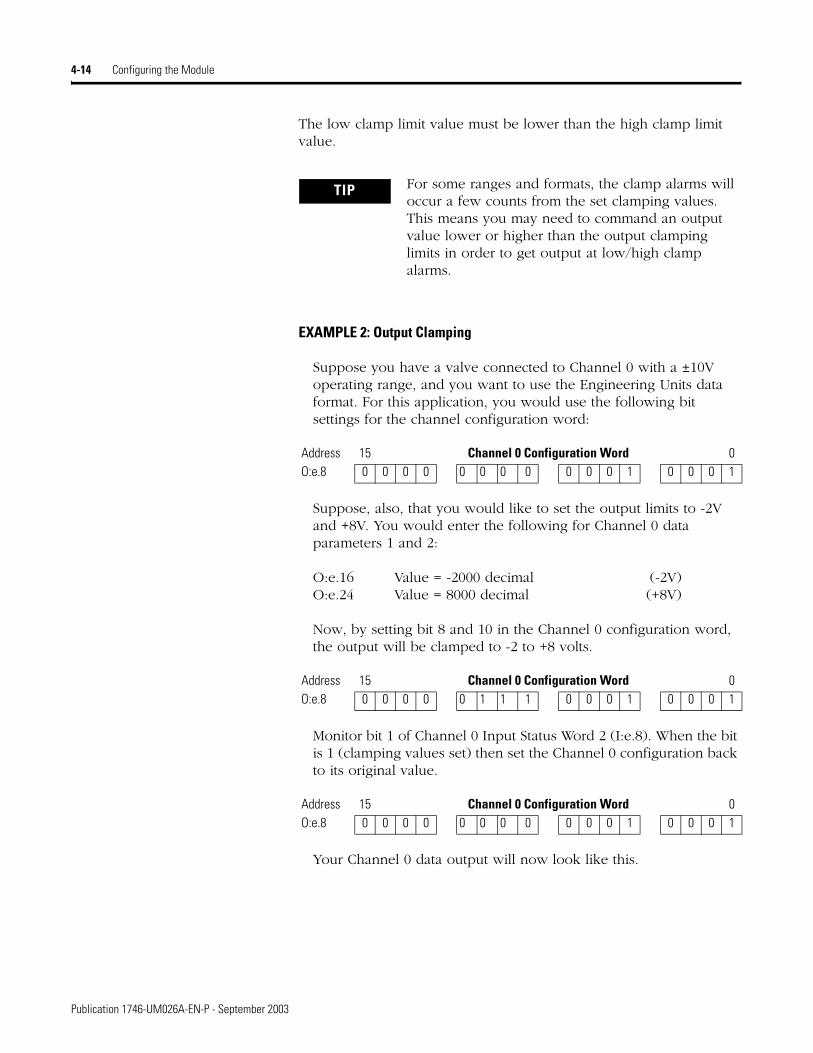
Output Clamping
For added safety, the 1746-NO8I and 1746-NO8V output modules let you define limits for the values in the output data words individually for all eight channels. These data limits, in turn, limit the output signals. When an output data word exceeds the data limit, the output value is truncated to the limit.
You can use output data limiting to prevent PID loops from exceeding safety limits, to prevent operators from inadvertently setting incorrect values, etc.
The low clamping limit (Output Data Parameter 1) is the value which the output signal will not go below. The high clamping limit (Output Data Parameter 2) is the value which the output signal will not go above.
Address 15 Channel 0 Configuration Word 0O:e.8 0 0 0 0 0 0 1 1 0 1 0 0 0 0 1 1
Address 15 Channel 0 Configuration Word 0O:e.8 0 0 0 0 0 0 0 0 0 1 0 0 0 0 1 1
100 9999
20.5 mA
3.5 mA
Data Value
Outp
ut S
igna
l
Publication 1746-UM026A-EN-P - September 2003
4-14 Configuring the Module
The low clamp limit value must be lower than the high clamp limit value.
EXAMPLE 2: Output Clamping
Suppose you have a valve connected to Channel 0 with a ±10V operating range, and you want to use the Engineering Units data format. For this application, you would use the following bit settings for the channel configuration word:
Suppose, also, that you would like to set the output limits to -2V and +8V. You would enter the following for Channel 0 data parameters 1 and 2:
O:e.16 Value = -2000 decimal (-2V)O:e.24 Value = 8000 decimal (+8V)
Now, by setting bit 8 and 10 in the Channel 0 configuration word, the output will be clamped to -2 to +8 volts.
Monitor bit 1 of Channel 0 Input Status Word 2 (I:e.8). When the bit is 1 (clamping values set) then set the Channel 0 configuration back to its original value.
Your Channel 0 data output will now look like this.
TIP For some ranges and formats, the clamp alarms will occur a few counts from the set clamping values. This means you may need to command an output value lower or higher than the output clamping limits in order to get output at low/high clamp alarms.
Address 15 Channel 0 Configuration Word 0O:e.8 0 0 0 0 0 0 0 0 0 0 0 1 0 0 0 1
Address 15 Channel 0 Configuration Word 0O:e.8 0 0 0 0 0 1 1 1 0 0 0 1 0 0 0 1
Address 15 Channel 0 Configuration Word 0O:e.8 0 0 0 0 0 0 0 0 0 0 0 1 0 0 0 1
Publication 1746-UM026A-EN-P - September 2003
Configuring the Module 4-15
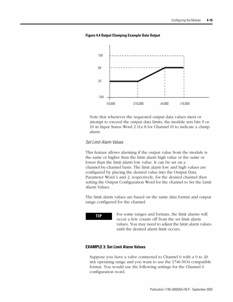
Figure 4.4 Output Clamping Example Data Output
Note that whenever the requested output data values meet or attempt to exceed the output data limits, the module sets bits 9 or 10 in Input Status Word 2 (I:e.8 for Channel 0) to indicate a clamp alarm.
Set Limit Alarm Values
This feature allows alarming if the output value from the module is the same or higher than the limit alarm high value or the same or lower than the limit alarm low value. It can be set on a channel-by-channel basis. The limit alarm low and high values are configured by placing the desired value into the Output Data Parameter Word 1 and 2, respectively, for the desired channel then setting the Output Configuration Word for the channel to Set the Limit Alarm Values
The limit alarm values are based on the same data format and output range configured for the channel.
EXAMPLE 3: Set Limit Alarm Values
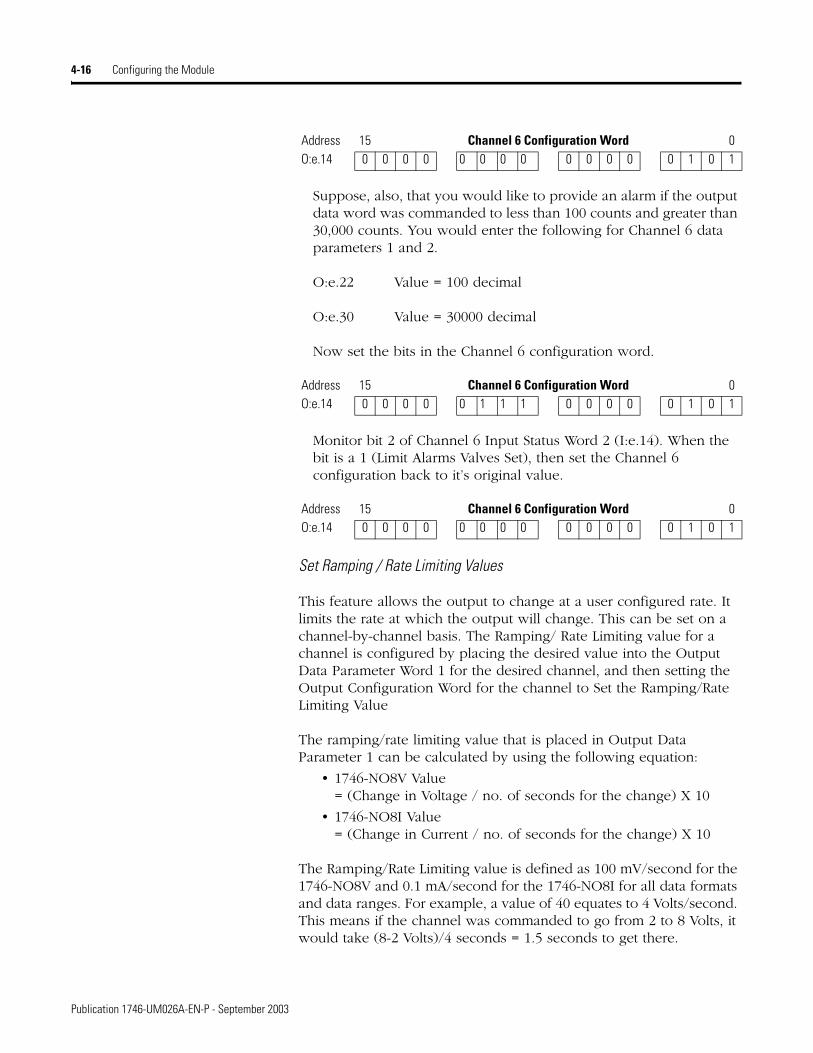
Suppose you have a valve connected to Channel 6 with a 0 to 20 mA operating range and you want to use the 1746-NO4 compatible format. You would use the following settings for the Channel 6 configuration word.
10V
-10,000
8V
2V
-10V
-210,000 +8,000 +10,000
TIP For some ranges and formats, the limit alarms will occur a few counts off from the set limit alarm values. You may need to adjust the limit alarm values until the desired alarm limit occurs.
Publication 1746-UM026A-EN-P - September 2003
4-16 Configuring the Module
Suppose, also, that you would like to provide an alarm if the output data word was commanded to less than 100 counts and greater than 30,000 counts. You would enter the following for Channel 6 data parameters 1 and 2.
O:e.22 Value = 100 decimal
O:e.30 Value = 30000 decimal
Now set the bits in the Channel 6 configuration word.
Monitor bit 2 of Channel 6 Input Status Word 2 (I:e.14). When the bit is a 1 (Limit Alarms Valves Set), then set the Channel 6 configuration back to it’s original value.
Set Ramping / Rate Limiting Values
This feature allows the output to change at a user configured rate. It limits the rate at which the output will change. This can be set on a channel-by-channel basis. The Ramping/ Rate Limiting value for a channel is configured by placing the desired value into the Output Data Parameter Word 1 for the desired channel, and then setting the Output Configuration Word for the channel to Set the Ramping/Rate Limiting Value
The ramping/rate limiting value that is placed in Output Data Parameter 1 can be calculated by using the following equation:
• 1746-NO8V Value = (Change in Voltage / no. of seconds for the change) X 10
• 1746-NO8I Value = (Change in Current / no. of seconds for the change) X 10
The Ramping/Rate Limiting value is defined as 100 mV/second for the 1746-NO8V and 0.1 mA/second for the 1746-NO8I for all data formats and data ranges. For example, a value of 40 equates to 4 Volts/second. This means if the channel was commanded to go from 2 to 8 Volts, it would take (8-2 Volts)/4 seconds = 1.5 seconds to get there.
Address 15 Channel 6 Configuration Word 0O:e.14 0 0 0 0 0 0 0 0 0 0 0 0 0 1 0 1
Address 15 Channel 6 Configuration Word 0O:e.14 0 0 0 0 0 1 1 1 0 0 0 0 0 1 0 1
Address 15 Channel 6 Configuration Word 0O:e.14 0 0 0 0 0 0 0 0 0 0 0 0 0 1 0 1
Publication 1746-UM026A-EN-P - September 2003

Configuring the Module 4-17
EXAMPLE 4: Set Ramping/Rate Limit Values
Suppose you have a valve connected to Channel 4 with a 4 to 20 mA operating range and you want to use PID format. You would use the following bit settings for the Channel 4 configuration word:
Suppose, also, that you would like the output to change no more than 1.5 mA per second.
Since the ramping value is expressed as 0.1 mA per second, your value would be 1.5 ÷ 0.1 = 15. You would enter the following for Channel 4 data parameter 1. Note, data parameter 2 is not used for ramping:
O:e.20 Value = 15 decimal (Channel 4 Data Parameter 1) (1.5mA per second)
Now set the bits in the Channel 4 configuration word:
Monitor bit 3 of Channel 4 Input Status Word 2 (I:e.12). When this bit is a 1 (Ramping/ Rate Limiting value set), then set the Channel 4 configuration back to its original value:
Ramping is now active.
Set Preset Fault Value
This feature allows you to define a preset output value for a fault condition. The value for a channel is configured by placing the desired value into Output Data Parameter Word 1 for the desired channel and then setting the Output Configuration Word for the channel to set the Preset Fault Value. The module will revert to this value when a fault condition occurs, if Preset Output on Fault is set. See Fault Options (configuration bits 12 and 13) on page 4-10 for information about fault conditions.
Address 15 Channel 4 Configuration Word 0O:e.12 0 0 0 0 0 0 0 0 0 0 1 0 0 0 1 1
Address 15 Channel 4 Configuration Word 0O:e.12 0 0 0 0 1 0 0 1 0 0 1 0 0 0 1 1
Address 15 Channel 4 Configuration Word 0O:e.12 0 0 0 0 0 0 0 0 0 0 1 0 0 0 1 1
Publication 1746-UM026A-EN-P - September 2003

4-18 Configuring the Module
EXAMPLE 5: Set Preset Fault Values
Suppose you have a valve connected to Channel 7 with a 4 to 20 mA operating range and you want to use Engineering Units format. You would use the following bit settings for the Channel 7 configuration word:
Suppose, also, that you would like the output to go to 12 mA if a fault condition occurred. You would enter the following for Channel 7 data parameter 1. (Note that data parameter 2 is not used for the Preset Fault Value.)
O:e.23 12000 (decimal) Channel 7 data parameter 1
Now set the bits in the Channel 7 configuration word:
Monitor bit 4 of Channel 7 Input Status Word 2 (I:e.15). When this bit is a 1 (Preset Fault Value set), then set the Channel 7 configuration back to its original value with the addition of setting the Channel 7 configuration word to Preset Output on Fault (bit 13):
If a fault is detected, then the output for Channel 7 will go to 12 mA.
Address 15 Channel 7 Configuration Word 0O:e.15 0 0 0 0 0 0 0 0 0 0 0 1 0 0 1 1
Address 15 Channel 7 Configuration Word 0O:e.15 0 0 0 0 1 0 1 1 0 0 0 1 0 0 1 1
Address 15 Channel 0 Configuration Word 0O:e.15 0 0 1 0 0 0 0 0 0 0 0 1 0 0 1 1
Publication 1746-UM026A-EN-P - September 2003
Configuring the Module 4-19
Ladder Program to Configure Channel 0
]/[I:1.8
1OTHER
0000
MOVMOVESource 20000
20000
Dest O:1.2410000
<
<
CH0_PARAMETER2
MOVMOVESource 5393
5393
Dest 0:1.84113
<
<
CH0_CONFIG
MOVMOVESource 4000
4000
Dest O:1.165000
<
<
CH0_PARAMETER1CH0_CLAMPING_SET
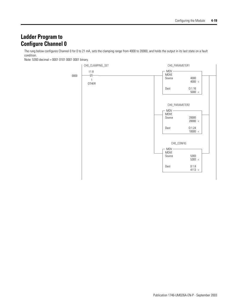
The rung below configures Channel 0 for 0 to 21 mA, sets the clamping range from 4000 to 20000, and holds the output in its last state on a fault condition. Note: 5393 decimal = 0001 0101 0001 0001 binary.
Publication 1746-UM026A-EN-P - September 2003

4-20 Configuring the Module
]/[I:1.8
2OTHER
] [I:1.8
1OTHER
0001
MOVMOVESource 10000
10000
Dest O:1.2410000
<
<
CH0_PARAMETER2
MOVMOVESource 5905
5905
Dest 0:1.84113
<
<
CH0_CONFIG
MOVMOVESource 5000
5000
Dest O:1.165000
<
<
CH0_PARAMETER1CH0_CLAMPING_SET CH0_LIMIT_AL_SET
The rung below configures Channel 0 for 0 to 21 mA, sets the alarm limit range from 5000 to 10000, and holds the output in its last state on a fault condition. Note: 5905 decimal = 0001 0111 0001 0001 binary.
]/[I:1.8
2OTHER
] [
(END)
I:1.8
1OTHER
0002
0003
MOVMOVESource 4113
4113
Dest O:1.84113
<
<
CH0_CONFIGCH0_CLAMPING_SET CH0_LIMIT_AL_SET
I:1.8/2 --> CH0_LIMIT_AL_SET
The rung below configures Channel 0 for 0 to 21 mA, sets the parameter option to “no action”, and holds the output in its last state on a fault condition. Note: 4113 decimal = 0001 0000 0001 0001 binary.
Publication 1746-UM026A-EN-P - September 2003

Chapter 5
I/O Data and Status Information
Read this chapter to:
• monitor each output channel
• check each channel’s configuration and status
Output Image and Input Image Overview
Output Image
The output image (defined as the output from the SLC processor to the module) defines how each channel on your module works.
Table 5.1 1746-NO8 Output Image Operation
Operating Mode
Output Image Size
Module Operation
Class 1 8-word The output data words control the output signal level for each channel.
Class 3 32-word • The output data words control the output signal level for each channel.
• The configuration words replace configuration DIP switches that may be used on other modules. Each configuration word configures one channel.
• The output data parameters 1 and 2 typically define low and high values for items such as limit alarms and output clamping. Ramping and preset output on fault only use output data parameter 1.
• Important - Class 3 features for any particular channel will only be active if the channel is enabled. Disabled channels will output 0V (0 mA) no matter what features are configured.
1 Publication 1746-UM026A-EN-P - September 2003
5-2 I/O Data and Status Information
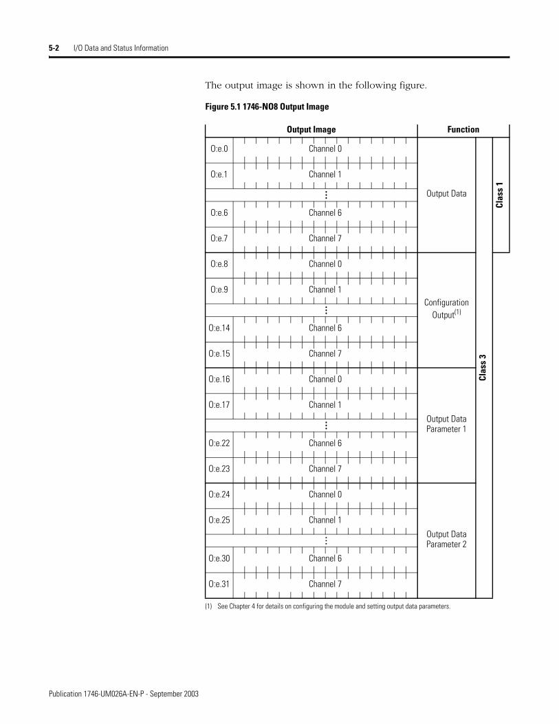
The output image is shown in the following figure.
Figure 5.1 1746-NO8 Output Image
Output Image Function
Output Data
Clas
s 3
Clas
s 1
O:e.0 Channel 0
O:e.1 Channel 1
…
O:e.6 Channel 6
O:e.7 Channel 7
Configuration Output(1)
(1) See Chapter 4 for details on configuring the module and setting output data parameters.
O:e.8 Channel 0
O:e.9 Channel 1
…O:e.14 Channel 6
O:e.15 Channel 7
Output Data Parameter 1
O:e.16 Channel 0
O:e.17 Channel 1
…
O:e.22 Channel 6
O:e.23 Channel 7
Output Data Parameter 2
O:e.24 Channel 0
O:e.25 Channel 1
…
O:e.30 Channel 6
O:e.31 Channel 7
Publication 1746-UM026A-EN-P - September 2003
I/O Data and Status Information 5-3
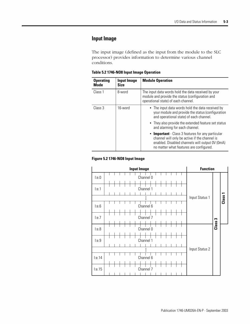
Input Image
The input image (defined as the input from the module to the SLC processor) provides information to determine various channel conditions.
Figure 5.2 1746-NO8 Input Image
Table 5.2 1746-NO8 Input Image Operation
Operating Mode
Input Image Size
Module Operation
Class 1 8-word The input data words hold the data received by your module and provide the status (configuration and operational state) of each channel.
Class 3 16-word • The input data words hold the data received by your module and provide the status (configuration and operational state) of each channel.
• They also provide the extended feature set status and alarming for each channel.
• Important - Class 3 features for any particular channel will only be active if the channel is enabled. Disabled channels will output 0V (0mA) no matter what features are configured.
Input Image Function
Input Status 1
Clas
s 3
Clas
s 1
I:e.0 Channel 0
I:e.1 Channel 1
…
I:e.6 Channel 6
I:e.7 Channel 7
Input Status 2
I:e.8 Channel 0
I:e.9 Channel 1
…
I:e.14 Channel 6
I:e.15 Channel 7
Publication 1746-UM026A-EN-P - September 2003

5-4 I/O Data and Status Information
Input Status Words Channel Input Status Word 1 (Class 1 and Class 3)
Words 0 through 7 of the input image file (addresses I:e.0 through I:e.7) reflect the configuration and status of each channel. Use the data provided in these status words to determine various channel conditions. Input Status 1 addressing and bit definitions are shown in the following figures:
Figure 5.3 Input Status 1
Input Image Words 0 through 7 Function
Input Status 1
Clas
s 1
and
Clas
s 3
I:e.0 Channel 0
I:e.1 Channel 1
…
I:e.6 Channel 6
I:e.7 Channel 7
Table 5.3 Input Status 1 Word Details
15 14 13 12 11 10 9 8 7 6 5 4 3 2 1 0Output channel disableOutput channel enable
01
1746-NO8V Output Ranges:±10V dc1 to 5V dc0 to 5V dc0 to 10V dc
0011
0101
1746-NO8I Output Ranges:0 to 21 mA4 to 20 mA0 to 20 mAInvalid
0011
0101
Invalid 0
1746-NO4 compatible formatEngineering unitsScaled for PIDProportional countsUser-defined scaleInvalidInvalidInvalid
00001111
00110011
01010101
Invalid 0 0 0 0 0
24V Power Failure 1
Current Loop Open 1
Module/SLC Resetting 1
Fatal Channel Error 1
Publication 1746-UM026A-EN-P - September 2003
I/O Data and Status Information 5-5
Input Status 1 Descriptions
Output Enable Echo (Status Bit 0)
This bit shows the current channel status. The channel is enabled when this bit echo is 1.
Output Range Echo (Status Bits 1 and 2)
These bits echo the current output range for the active channel.
Scale Echo (Status Bits 4 to 6)
These bits shows the current channel data format setting
24V Power Failure Echo (Status Bit 12)
This bit is set to 1 if the external 24V dc power supply (selected via Jumper J4) has failed. This bit will clear when the external 24V dc supply is present and, if the Latch Alarms feature is enabled, the Reset Latched Alarms bit has been set or toggled.
If the J4 jumper is missing, the module will report a 24V dc power fail, regardless of whether external 24 V dc power is present or not.
Open Current Loop (Status Bit 13)
This bit is set to 1 if there is no load (open loop) on the output channel. Open loop detect will only be indicated if the current being commanded is greater than 0.1 mA. Invalid open loop detection may occur if the channel load resistance is greater than the specified maximum resistance of 500 ohms, or less than 0.1 mA is commanded. This bit will clear when the channel is no longer in an open loop condition (or commanding less than 0.1 mA) and, if the Latch Alarms feature is enabled, the Reset Latched Alarms bit has been set or toggled.
Module / SLC Resetting (Status Bit 14)
This bit is set to 1 whenever the module or SLC is resetting. The bit will clear when both the module and the SLC are not resetting. This bit is not latched by the Latch Alarm feature. Do not send configuration data to the module when this bit is set
Fatal Channel Error (Status Bit 15)
This bit is set to 1 whenever your module detects a “non-recoverable” channel error, such as a software power-up failure due to corrupt hardware or malfunctioning software. You may be able to recover from this type of error by resetting the SLC 500 processor or cycling power to your module. This bit is not latched by the Latch Alarm feature.
Publication 1746-UM026A-EN-P - September 2003

5-6 I/O Data and Status Information
Channel Input Status Word 2 (Class 3 Only)
Words 8 through 15 of the input image file (addresses I:e.8 through I:e.15) reflect the parameter options, fault settings, and alarm options for each channel. Input Status 2 addressing and bit definitions are shown in the following figures:
Figure 5.4 Input Status 2
Input Image Words 0 through 7 Function
Input Status 2
Clas
s 3
I:e.8 Channel 0
I:e.9 Channel 1
…
I:e.14 Channel 6
I:e.15 Channel 7
Table 5.4 Input Status 2 Word Details
15 14 13 12 11 10 9 8 7 6 5 4 3 2 1 0
User Scaling Values Set 1
Clamping Values Set 1
Limit Alarm Values Set 1
Ramping/Rate Limiting Values Set 1
Preset Fault Value Set 1
Reset Output on Fault 1
Hold Output on Fault 1
Preset Output on Fault 1
Alarms Will Be latched 1
Output at Low Clamp Alarm 1
Output at High Clamp Alarm 1
Low Limit Alarm 1
High Limit Alarm 1
Under Range Alarm 1
Over Range Alarm 1
Channel Configuration Error 1
Publication 1746-UM026A-EN-P - September 2003

I/O Data and Status Information 5-7
Input Status 2 Descriptions
User Scaling Values Set (Status Bit 0)
This bit indicates that user scaling values have been set for this channel. If the channel format is user scaling and the channel is enabled, user scaling is active.
Clamping Values Set (Status Bit 1)
This bit indicates that clamping values have been set for the channel. If the channel is enabled, then clamping is active.
Limit Alarm Values Set (Status Bit 2)
This bit indicates that limit alarms have been set for the channel. If the channel is enabled, then limit alarms is active.
Ramping/Rate Limiting Value Set (Status Bit 3)
This bit indicates that ramping/rate limiting has been set. If the channel is enabled, then ramping/rate limiting is active.
Preset Fault Value Set (Status Bit 4)
This bit indicates that a user-defined fault value is set for this channel. See Fault Options (configuration bits 12 and 13) on page 4-10 for information on fault settings and fault conditions.
Reset Output On Fault (Status Bit 5)
This bit indicates that the output for this channel will be reset if a channel fault occurs. See Fault Options (configuration bits 12 and 13) on page 4-10 for information on fault settings and fault conditions.
Hold Output On Fault (Status Bit 6)
This bit indicates that the channel output value will be held to the current value when a channel fault occurs. See Fault Options (configuration bits 12 and 13) on page 4-10 for information on fault settings and fault conditions.
Preset Output On Fault (Status Bit 7)
This bit indicates that the channel output will go to the user defined preset when a channel fault occurs. See Fault Options (configuration bits 12 and 13) on page 4-10 for information on fault settings and fault conditions.
Publication 1746-UM026A-EN-P - September 2003
5-8 I/O Data and Status Information
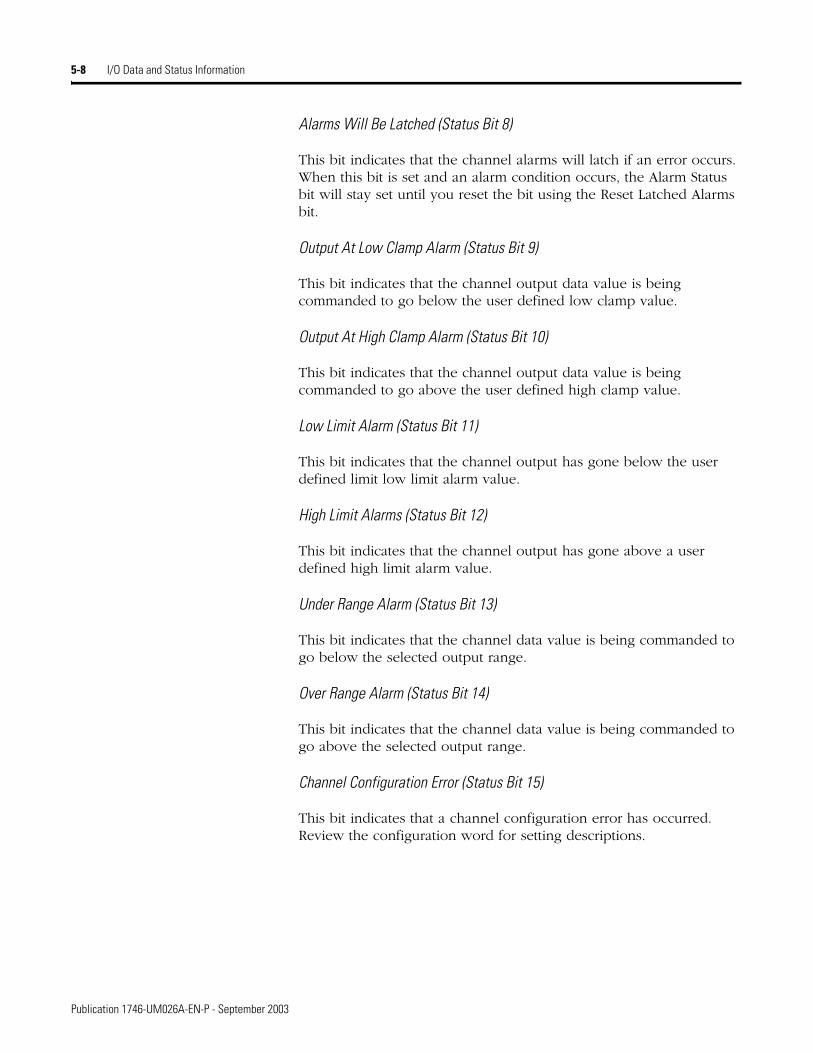
Alarms Will Be Latched (Status Bit 8)
This bit indicates that the channel alarms will latch if an error occurs. When this bit is set and an alarm condition occurs, the Alarm Status bit will stay set until you reset the bit using the Reset Latched Alarms bit.
Output At Low Clamp Alarm (Status Bit 9)
This bit indicates that the channel output data value is being commanded to go below the user defined low clamp value.
Output At High Clamp Alarm (Status Bit 10)
This bit indicates that the channel output data value is being commanded to go above the user defined high clamp value.
Low Limit Alarm (Status Bit 11)
This bit indicates that the channel output has gone below the user defined limit low limit alarm value.
High Limit Alarms (Status Bit 12)
This bit indicates that the channel output has gone above a user defined high limit alarm value.
Under Range Alarm (Status Bit 13)
This bit indicates that the channel data value is being commanded to go below the selected output range.
Over Range Alarm (Status Bit 14)
This bit indicates that the channel data value is being commanded to go above the selected output range.
Channel Configuration Error (Status Bit 15)
This bit indicates that a channel configuration error has occurred. Review the configuration word for setting descriptions.
Publication 1746-UM026A-EN-P - September 2003
Chapter 6
Module Diagnostics and Troubleshooting
Read this chapter to prevent potential problems. This chapter covers:
• inspecting your module
• disconnecting prime movers
• power-up diagnostics
• interpreting the LED indicators
• interpreting I/O error codes
• troubleshooting
Before testing your module, test your SLC 500 system using the procedures described in your controller’s User Manual.
Inspecting Your Module You can prevent many potential problems by inspecting the module:
1. Ensure that the external 24V dc jumper, J4, is set properly:
• With the jumper in the RACK position, the module draws all its power from the backplane of the SLC system.
• With the jumper in the EXT position, the module draws its 24V dc power from an external power source; however, the module still draws its 5V dc power from the backplane.
• If the J4 jumper is missing, the module will report a 24V dc power fail, regardless of whether external 24 V dc power is present or not.
2. Ensure that all wire connections are correct and secure and that no wires are missing or broken. See Chapter 2, Installation and Wiring, for more information.
3. Ensure that the shield for the cable used to wire your module is properly grounded.
4. Ensure that the removable terminal block on your module is secure.
IMPORTANT If your module appears to be functioning, but the terminals are not providing an output signal, the 24V dc power source (backplane or external) may not be providing enough current. Current consumption at 24V dc is 250 mA for the 1746-NO8I and 160 mA for the 1746-NO8V.
1 Publication 1746-UM026A-EN-P - September 2003
6-2 Module Diagnostics and Troubleshooting
Disconnecting Prime Movers
Before testing your module, ensure that machine motion will not occur:
• Disconnect motor wires at the motor starter or the motor itself. This allows you to test the operation of the starter coil, verifying that the output circuit is wired correctly and functioning.
• Disconnect solenoids by disengaging the solenoid valves, leaving the coils connected.
If you cannot disconnect a device in the preferred way, open the output circuit as close as possible to the motion-causing device.
Power-Up Diagnostics When you apply power to the system, the module’s LEDs should illuminate, indicating that your module is receiving power and has completed its internal diagnostic self-test. If the LEDs do not illuminate after several seconds, the module is not functional. Discontinue testing until you can get the LEDs to illuminate.
The most probable reasons for the LED not illuminating are:
• The SLC 500 system is not receiving power from its power supply.
• The rest of the SLC 500 system is not receiving power.
• The chassis slot where your module is located is defective.
• The analog module is defective.
EXAMPLE If you have a relay coil that, in turn, energizes a motor starter and you cannot disconnect the motor wires, open the circuit at a point between the motor starter and the relay contact.
WARNING
!POSSIBLE UNEXPECTED MACHINE MOTION
During all testing, always disconnect all devices that, when energized, might cause machine motion.
Failure to observe this precaution may cause equipment damage or personal injury.
TIP If the module is configured to use an external 24V dc power supply, the supply must be turned on for the module to operate. If the external 24V dc supply is turned off, the module’s outputs will be turned off, and the module’s processor will be reset until power is restored.
Publication 1746-UM026A-EN-P - September 2003

Module Diagnostics and Troubleshooting 6-3
Interpreting the LED Indicators
The module has 9 LEDs: • 8 channel status LEDs (for Channels 0 through 7)
• 1 module status LED
Figure 6.1 Module LEDs
Use the following table to interpret the LEDs:
OUTPUT
CHANNELSTATUS
MODULE
ANALOG
0
1
2
3
4
5
6
7
Table 6.1 1746-NO8 LED Indications
Module LED Status Channel LED Status Indicates
On solid On solid The channel is enabled.
On solid On flashing, 1-flash sequence Open circuit.
On solid On flashing, 2-flash sequence Unused configuration word bits are set
On solid On flashing, 3-flash sequence Illegal range
On solid On flashing, 4-flash sequence Illegal format
On solid On flashing, 5-flash sequence Illegal parameter ID
On solid On flashing, 6-flash sequence User range error (e.g. User_min > User_max)
On solid On flashing, 7-flash sequence Clamp range error
On solid On flashing, 8-flash sequence Illegal fault action
On solid On flashing, 9-flash sequence illegal ramp value
On solid On flashing, 10-flash sequence Illegal limit range
On solid On flashing, 11-flash sequence Illegal preset
On solid On flashing, 12-flash sequence Illegal optional features
On solid Off Module is powering up or the channel is disabled.
On flashing, 1-flash sequence n/a 24V power fail or J4 jumper is missing
On flashing, 2-flash sequence n/a Configuration error
On flashing, 3-flash sequence n/a EEPROM fault
On flashing, 4-flash sequence n/a RAM fault
On flashing, 5-flash sequence n/a Input access error
On flashing, 6-flash sequence n/a Output access error
On flashing, 7-flash sequence n/a ROM CRC failed
Off n/a Module fault condition
Publication 1746-UM026A-EN-P - September 2003
6-4 Module Diagnostics and Troubleshooting
Interpreting I/O Error Codes I/O error codes appear in word S:6 of the SLC 500 processor status file. The first two digits of the error code identify the slot (in hexadecimal) experiencing the error. The last two digits identify the I/O error code (in hexadecimal).
The error codes that apply to the 1746-NO8 module include (in hexadecimal):
• 50 to 5E (I/O errors)
• 71 (watchdog error)
• 90 to 94 (I/O errors)
Refer to the SLC 500 Instruction Set Reference Manual, publication 1747-RM001 for a complete listing of error codes, probable causes, and recovery information.
Publication 1746-UM026A-EN-P - September 2003
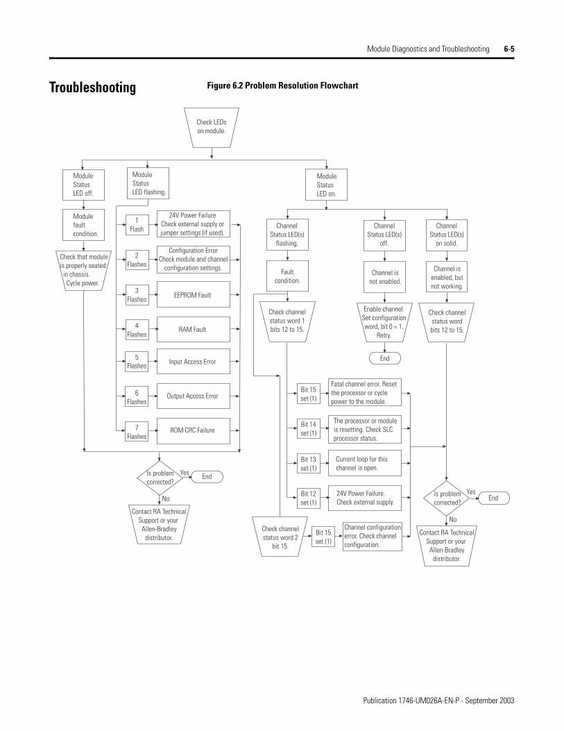
Module Diagnostics and Troubleshooting 6-5
Troubleshooting Figure 6.2 Problem Resolution Flowchart
Check that moduleis properly seated in chassis. Cycle power.
Module fault condition.
Module Status LED off.
Module Status LED flashing.
Module Status LED on.
1Flash
2Flashes
3Flashes
4Flashes
5Flashes
6Flashes
7Flashes
24V Power FailureCheck external supply orjumper settings (if used).
Configuration ErrorCheck module and channel
configuration settings.
EEPROM Fault
RAM Fault
Input Access Error
Output Access Error
ROM CRC Failure
Is problemcorrected?
Yes
NoIs problemcorrected?
Yes
No
End
End
End
Contact RA TechnicalSupport or your
Allen-Bradleydistributor.
Contact RA TechnicalSupport or your
Allen-Bradleydistributor.
Check LEDson module.
ChannelStatus LED(s)
flashing.
ChannelStatus LED(s)
off.
ChannelStatus LED(s)
on solid.
Channel isenabled, butnot working.
Channel isnot enabled.
Faultcondition.
Check channelstatus wordbits 12 to 15.
Enable channel.Set configurationword, bit 0 = 1.
Retry.
Check channelstatus word 1bits 12 to 15.
Bit 15set (1)
Bit 15set (1)
Bit 14set (1)
Bit 13set (1)
Bit 12set (1)
Fatal channel error. Reset the processor or cycle power to the module.
The processor or module is resetting. Check SLCprocessor status.
Current loop for thischannel is open.
24V Power Failure. Check external supply.
Check channelstatus word 2
bit 15.
Channel configuration error. Check channelconfiguration.
Publication 1746-UM026A-EN-P - September 2003

6-6 Module Diagnostics and Troubleshooting
Publication 1746-UM026A-EN-P - September 2003
Chapter 7
Maintenance and Safety
Read this chapter to familiarize yourself with:
• preventive maintenance
• safety considerations
Preventative Maintenance The printed circuit boards of the analog modules must be protected from dirt, oil, moisture and other airborne contaminants. To protect these boards, install the SLC 500 system in an enclosure suitable for its operating environment. Keep the interior of the enclosure clean, and whenever possible, keep the enclosure door closed.
Regularly inspect your terminal connections for tightness. Loose connections may cause a malfunction in the SLC 500 system or damage the components of the system.
For general maintenance procedures for electrical equipment, refer to the requirements specific to your region.
• Europe: Refer to the standards found in EN 60204 and your national regulations.
• United States: Refer to article 70B of the National Fire Protection Association (NFPA). It describes general requirements regarding safety related work practices.
Safety Considerations while Troubleshooting
Safety considerations are an important element of proper troubleshooting procedures. Actively think about the safety of yourself and others, as well as the condition of your equipment. Refer to your controller’s User Manual for additional information on troubleshooting.
ATTENTION
!To ensure personal safety and to guard against damaging equipment, inspect connections with incoming power OFF.
Failure to observe this precaution can cause personal injury and equipment damage.
1 Publication 1746-UM026A-EN-P - September 2003
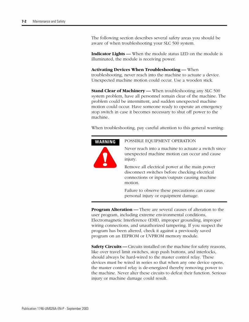
7-2 Maintenance and Safety
The following section describes several safety areas you should be aware of when troubleshooting your SLC 500 system.
Indicator Lights — When the module status LED on the module is illuminated, the module is receiving power.
Activating Devices When Troubleshooting — When troubleshooting, never reach into the machine to actuate a device. Unexpected machine motion could occur. Use a wooden stick.
Stand Clear of Machinery — When troubleshooting any SLC 500 system problem, have all personnel remain clear of the machine. The problem could be intermittent, and sudden unexpected machine motion could occur. Have someone ready to operate an emergency stop switch in case it becomes necessary to shut off power to the machine.
When troubleshooting, pay careful attention to this general warning:
Program Alteration — There are several causes of alteration to the user program, including extreme environmental conditions, Electromagnetic Interference (EMI), improper grounding, improper wiring connections, and unauthorized tampering. If you suspect the program has been altered, check it against a previously saved program on an EEPROM or UVPROM memory module.
Safety Circuits — Circuits installed on the machine for safety reasons, like over travel limit switches, stop push buttons, and interlocks, should always be hard-wired to the master control relay. These devices must be wired in series so that when any one device opens, the master control relay is de-energized thereby removing power to the machine. Never alter these circuits to defeat their function. Serious injury or machine damage could result.
WARNING
!POSSIBLE EQUIPMENT OPERATION
Never reach into a machine to actuate a switch since unexpected machine motion can occur and cause injury.
Remove all electrical power at the main power disconnect switches before checking electrical connections or inputs/outputs causing machine motion.
Failure to observe these precautions can cause personal injury or equipment damage.
Publication 1746-UM026A-EN-P - September 2003
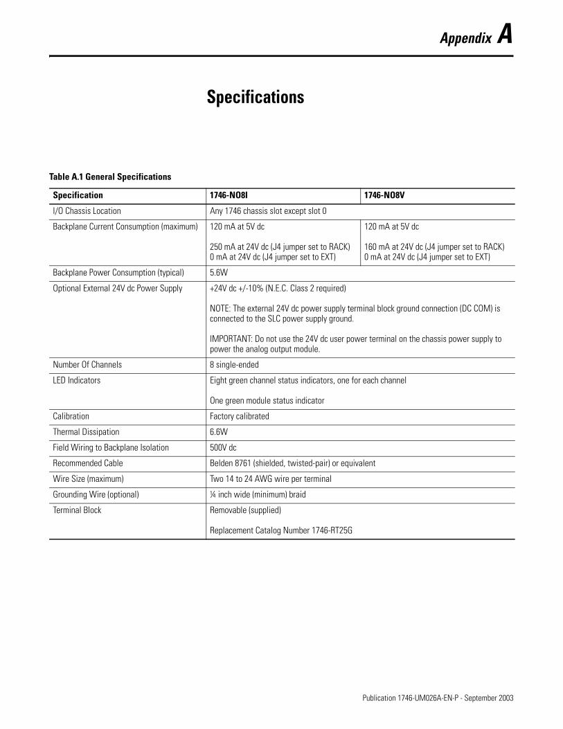
Appendix A
Specifications
Table A.1 General Specifications
Specification 1746-NO8I 1746-NO8V
I/O Chassis Location Any 1746 chassis slot except slot 0
Backplane Current Consumption (maximum) 120 mA at 5V dc
250 mA at 24V dc (J4 jumper set to RACK)0 mA at 24V dc (J4 jumper set to EXT)
120 mA at 5V dc
160 mA at 24V dc (J4 jumper set to RACK)0 mA at 24V dc (J4 jumper set to EXT)
Backplane Power Consumption (typical) 5.6W
Optional External 24V dc Power Supply +24V dc +/-10% (N.E.C. Class 2 required)
NOTE: The external 24V dc power supply terminal block ground connection (DC COM) is connected to the SLC power supply ground.
IMPORTANT: Do not use the 24V dc user power terminal on the chassis power supply to power the analog output module.
Number Of Channels 8 single-ended
LED Indicators Eight green channel status indicators, one for each channel
One green module status indicator
Calibration Factory calibrated
Thermal Dissipation 6.6W
Field Wiring to Backplane Isolation 500V dc
Recommended Cable Belden 8761 (shielded, twisted-pair) or equivalent
Wire Size (maximum) Two 14 to 24 AWG wire per terminal
Grounding Wire (optional) ¼ inch wide (minimum) braid
Terminal Block Removable (supplied)
Replacement Catalog Number 1746-RT25G
1 Publication 1746-UM026A-EN-P - September 2003

A-2 Specifications
Table A.2 Analog Output Specifications
Specification 1746-NO8I 1746-NO8V
Number of Outputs 8 8
Output Type Current Voltage
Output Range 0 to 21.5 mA ±10.25V dc
Output Coding (proportional scaling) 0 to 32,767 -32,768 to +32,767
Output D/A Converter Resolution 16-bit
366 nA/count
16-bit
320 µV/count
Location of LSB in I/O Image Word 0000 0000 0000 0001 (for 1746-NO4 compatible data format; does not apply to other data formats)
Non-Linearity 0.06% of full scale
DAC Conversion Method R-2R Ladder Network
Output Step Response Time 1 ms (0 to 95% of full scale)
Channel Update Time (typical) Class 1: 5 ms to update all 8 channels
Class 3: 10 ms to update all 8 channels
Load Range 0 to 500 ohm 1K ohm and greater
Load Current n/a 10 mA (maximum)
Load Reactance 1 µH (maximum) 1 µF (maximum)
Output Impedance Greater than 1M ohm Less than 1.0 ohm
Over-Range Capability 7.5% (21.5mA) 2.5% (±10.25V)
Overall Accuracy 0.1% of full scale at 25°C
0.2% of full scale at 60°C
0.1% of full scale at 25°C
0.2% of full scale at 60°C
Overall Accuracy Drift ±33 ppm/°C of full scale (maximum) ±33 ppm/°C of full scale (maximum)
Gain Error 0.08% of full scale at 25°C
0.15% of full scale at 60°C
0.08% of full scale at 25°C
0.15% of full scale at 60°C
Gain Error Drift ±25 ppm/°C of full scale (maximum) ±25 ppm/°C of full scale (maximum)
Offset Error ±12 LSB at 25°C (typical)
±29 LSB at 60°C (typical)
±13 LSB at 25°C (typical)
±32 LSB at 60°C (typical)
Offset Error Drift ±0.48 LSB/°C (maximum) ±0.53 LSB/°C (maximum)
Publication 1746-UM026A-EN-P - September 2003
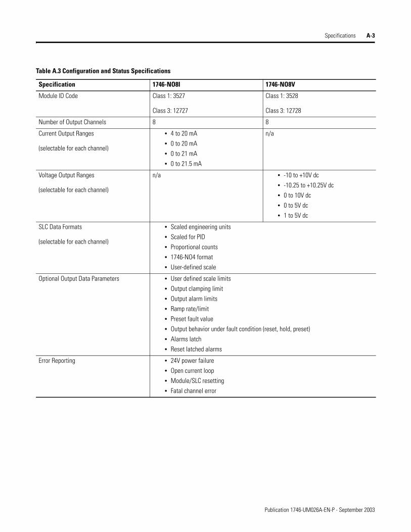
Specifications A-3
Table A.3 Configuration and Status Specifications
Specification 1746-NO8I 1746-NO8V
Module ID Code Class 1: 3527
Class 3: 12727
Class 1: 3528
Class 3: 12728
Number of Output Channels 8 8
Current Output Ranges
(selectable for each channel)
• 4 to 20 mA
• 0 to 20 mA
• 0 to 21 mA
• 0 to 21.5 mA
n/a
Voltage Output Ranges
(selectable for each channel)
n/a • -10 to +10V dc
• -10.25 to +10.25V dc
• 0 to 10V dc
• 0 to 5V dc
• 1 to 5V dc
SLC Data Formats
(selectable for each channel)
• Scaled engineering units
• Scaled for PID
• Proportional counts
• 1746-NO4 format
• User-defined scale
Optional Output Data Parameters • User defined scale limits
• Output clamping limit
• Output alarm limits
• Ramp rate/limit
• Preset fault value
• Output behavior under fault condition (reset, hold, preset)
• Alarms latch
• Reset latched alarms
Error Reporting • 24V power failure
• Open current loop
• Module/SLC resetting
• Fatal channel error
Publication 1746-UM026A-EN-P - September 2003
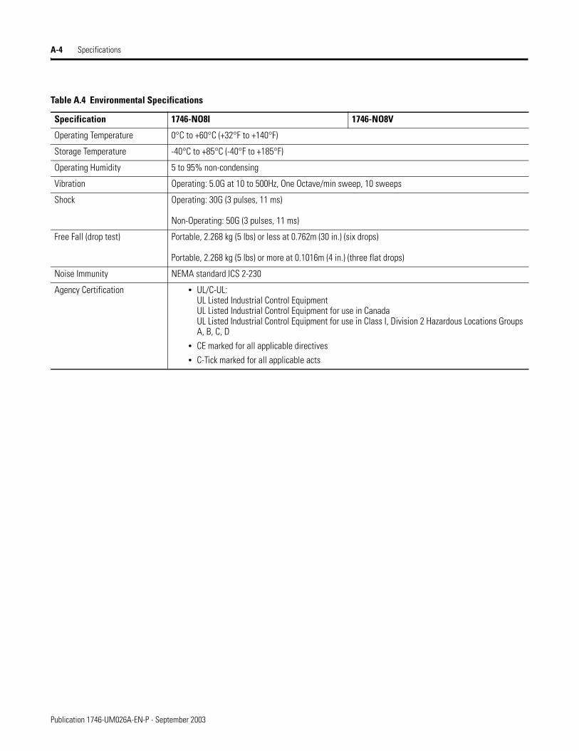
A-4 Specifications
Table A.4 Environmental Specifications
Specification 1746-NO8I 1746-NO8V
Operating Temperature 0°C to +60°C (+32°F to +140°F)
Storage Temperature -40°C to +85°C (-40°F to +185°F)
Operating Humidity 5 to 95% non-condensing
Vibration Operating: 5.0G at 10 to 500Hz, One Octave/min sweep, 10 sweeps
Shock Operating: 30G (3 pulses, 11 ms)
Non-Operating: 50G (3 pulses, 11 ms)
Free Fall (drop test) Portable, 2.268 kg (5 lbs) or less at 0.762m (30 in.) (six drops)
Portable, 2.268 kg (5 lbs) or more at 0.1016m (4 in.) (three flat drops)
Noise Immunity NEMA standard ICS 2-230
Agency Certification • UL/C-UL:UL Listed Industrial Control EquipmentUL Listed Industrial Control Equipment for use in CanadaUL Listed Industrial Control Equipment for use in Class I, Division 2 Hazardous Locations Groups A, B, C, D
• CE marked for all applicable directives
• C-Tick marked for all applicable acts
Publication 1746-UM026A-EN-P - September 2003
Appendix B
Replacing 1746-NO4s with 1746-NO8
Converting from 1746-NO4 to 1746-NO8
This information is provided for those who are replacing two 1746-NO4 modules with one 1746-NO8 module.
When using the 1746-NO8 module in Class 1 mode, no changes to the user program are required, except that the addressing will change when using one 1746-NO8 to replace two 1746-NO4 modules (see addressing example that follows). Additional status feedback is also available, and monitoring logic may be added if desired.
Module ID Code
The module identification code is a unique number encoded for each 1746 I/O module. The code defines for the processor the type of I/O or specialty module residing in a specific slot in the 1746 chassis.
The 1746-NO8 supports either Class 1, or Class 3 interface, while the 1746-NO4 supports only Class 1. When directly replacing 1746-NO4 modules, the Class 1 interface should be used if direct replacement with minimal program changes is desired. The Class 3 interface offers additional user configuration flexibility. However, additional user program modifications will be required to make use of these features. Refer to Chapters 3 and 4 for further definition of the Class 3 interface and programming software requirements.
Using your programming device, configure the slot with the appropriate code. In this example, the 1746-NO8 is in slot 3.
Table B.1 1746-NO8 Modules ID Codes
Catalog Number Module ID Code
1746-NO8I 3527 class 1 mode (8 inputs/8 outputs)
12727 class 3 mode (16 inputs/32 outputs)
1746-NO8V 3528 class 1 mode (8 inputs/8 outputs)
12728 class 3 mode (16 inputs/32 outputs)
1 Publication 1746-UM026A-EN-P - September 2003

B-2 Replacing 1746-NO4s with 1746-NO8
Module Addressing
Addressing is changed from two modules with 4 channels to one module with 8 channels. The output addressing is shown below.
Analog Conversion
The following information is provided for reference only; the 1746-NO8 is directly compatible with the 1746-NO4 when used in Class 1 mode.
The 1746-NO8 converts a 16-bit two’s complement binary value into an analog output signal using a 16-bit converter.
In 1746-NO4 compatible mode (e.g. Class 1), the 14 most significant bits are used, as the 1746-NO4 uses a 14 bit converter.
The following tables identify the current and voltage output ranges for the output channels, and their resolution when using 1746-NO4 compatible mode.
1746-NO4 Output Addressing• O:3.0 - Slot 3, Channel 0 Data Word • O:4.0 - Slot 4, Channel 0 Data Word• O:3.1 - Slot 3, Channel 1 Data Word • O:4.1 - Slot 4, Channel 1 Data Word• O:3.2 - Slot 3, Channel 2 Data Word • O:4.2 - Slot 4, Channel 2 Data Word• O:3.3 - Slot 3, Channel 3 Data Word • O:4.3 - Slot 4, Channel 3 Data Word
1746-NO8 Output Addressing• O:3.0 - Slot 3, Channel 0 Data Word • O:3.4 - Slot 3, Channel 4 Data Word• O:3.1 - Slot 3, Channel 1 Data Word • O:3.5 - Slot 3, Channel 5 Data Word• O:3.2 - Slot 3, Channel 2 Data Word • O:3.6 - Slot 3, Channel 6 Data Word• O:3.3 - Slot 3, Channel 3 Data Word • O:3.7 - Slot 3, Channel 7 Data Word
Table B.2 1746-NO8I and 1746-NO4I Output Range
Current Range Decimal Representation for Output Word
Resolution per LSB
0 to 21 mA 0 to 32,764 2.56348 A
0 to 20 mA 0 to 31,208
4 to 20 mA 6,242 to 31,208
NO4
NO4
SLOT 0 1 2 3 4 5 6
NO8
SLOT 0 1 2 3 4 5 6
Publication 1746-UM026A-EN-P - September 2003
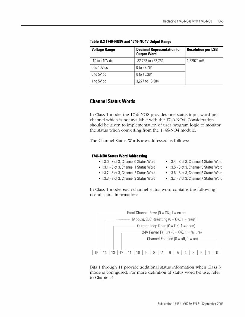
Replacing 1746-NO4s with 1746-NO8 B-3
Channel Status Words
In Class 1 mode, the 1746-NO8 provides one status input word per channel which is not available with the 1746-NO4. Consideration should be given to implementation of user program logic to monitor the status when converting from the 1746-NO4 module.
The Channel Status Words are addressed as follows:
In Class 1 mode, each channel status word contains the following useful status information:
Bits 1 through 11 provide additional status information when Class 3 mode is configured. For more definition of status word bit use, refer to Chapter 4.
Table B.3 1746-NO8V and 1746-NO4V Output Range
Voltage Range Decimal Representation for Output Word
Resolution per LSB
-10 to +10V dc -32,768 to +32,764 1.22070 mV
0 to 10V dc 0 to 32,764
0 to 5V dc 0 to 16,384
1 to 5V dc 3,277 to 16,384
1746-NO8 Status Word Addressing• I:3.0 - Slot 3, Channel 0 Status Word • I:3.4 - Slot 3, Channel 4 Status Word• I:3.1 - Slot 3, Channel 1 Status Word • I:3.5 - Slot 3, Channel 5 Status Word• I:3.2 - Slot 3, Channel 2 Status Word • I:3.6 - Slot 3, Channel 6 Status Word• I:3.3 - Slot 3, Channel 3 Status Word • I:3.7 - Slot 3, Channel 7 Status Word
15 14 13 12 11 10 9 8 7 6 5 4 3 2 1 0
Fatal Channel Error (0 = OK, 1 = error) Module/SLC Resetting (0 = OK, 1 = reset) Current Loop Open (0 = OK, 1 = open) 24V Power Failure (0 = OK, 1 = failure) Channel Enabled (0 = off, 1 = on)
Publication 1746-UM026A-EN-P - September 2003

B-4 Replacing 1746-NO4s with 1746-NO8
Publication 1746-UM026A-EN-P - September 2003
Glossary
You should understand the following terms and abbreviations before using this guide. For the definitions of terms not listed here, refer to Allen-Bradley Industrial Automation Glossary, publication AG-7.1
Channel Refers to one of the sets of signal interfaces available on a module’s terminal block.
Channel update time
For analog outputs, the time required for the channel to convert the data received from the processor to analog output signals at the terminals.
Chassis A hardware assembly that houses devices such as I/O modules, adapter modules, processor modules, and power supplies.
Configuration word
Contains the channel configuration information needed by the module to configure and operate each channel. Information is written to the configuration word through the logic supplied in your ladder program.
D/A Refers to digital-to-analog conversion. The conversion produces an analog output signal whose magnitude is proportional to the digital value.
Data scaling The data format that you select to define the logical increments of the channel data word.
Data word A 16-bit integer that represents the value of the analog output channel. The channel data word is valid only when the channel is enabled and there are no channel errors.
LSB (least signifi-cant bit)
The bit that represents the smallest value within a string of bits. The weight of this value is defined as the full scale range divided by the resolution.
Module ID code A unique number associated with each 1746 I/O module. The code defines for the processor the type of I/O or specialty module residing in a specific slot in the 1746 chassis.
Module update time
See channel update time.
Overall accuracy The worst-case deviation of the signal over the full range, expressed in percent of full scale.
Rack A hardware assembly that houses devices such as I/O modules, adapter modules, processor modules, and power supplies.
1 Publication 1746-UM026A-EN-P - September 2003

Glossary 2
Repeatability The closeness of agreement among repeated measurements of the same variable under the same conditions.
Resolution The smallest detectable change in a measurement, typically expressed in engineering units (e.g. microseconds) or as a number of bits. For example, a 16-bit system has 65536 possible output states. It can therefore measure 1 part in 65536. See also effective resolution.
Status word Contains status information about the channel’s current configuration and operational state. You can use this information in your ladder program to determine whether the channel data word is valid.
Step response time
The time required for the output signal to reach 95% of its expected, final value, given a full-scale step change in the output data word.
Publication 1746-UM026A-EN-P - September 2003

Index
Numerics1747-ACN(R)15 3-21747-ASB 3-2
AA.I. Series 3-2Advanced Programming Software (APS)
3-2
Bbackplane
connector 2-8electrostatic damage 2-3
block transfer 3-2
Ccable tie slots 1-2channel LED status 6-3channel status LED indicators 1-2chassis
installing module in 2-8Class 1 and Class 3 operation 3-2common techniques used in this manual
P-1compatible SLC processors 3-2connection diagram 2-11ControlNet chassis 3-2current draw 2-3
Ddiagnostics 6-1disabling a slot 3-4door label 1-2
Eelectrostatic damage 2-3EMC Directive 2-1emergency stop switch 7-2error codes 6-4European Union Directives 2-1external 24V dc power supply 2-4, 2-5
Ffeatures and benefits 1-1flashing LED 6-3
Hhardware features 1-2hazardous location considerations 2-2
IID code 3-1, 3-2image table 3-3input image 3-2, 3-3inspecting your module 6-1installation 2-1, 2-8
JJ4 jumper 1-2, 2-4, 5-5, 6-1
LLEDs 1-2, 6-3, 7-2
channel status indicators 1-2module status indicator 1-2
Low Voltage Directive 2-2
Mmaintenance 7-1manuals, related P-2module ID code 3-1
how to enter 3-2module installation and removal 2-7module LED status 6-3module removal procedure 2-8module status LED 1-2
Nnameplate 1-2
Ooperating considerations 3-1output and input scans 3-3output image 3-3
Ppower requirements 2-3power supply 2-4, 2-5power-up diagnostics 6-2preventative maintenance 7-1programming 7-2programming software 3-2
Publication 1746-UM026A-EN-P - September 2003
ii Index
publications, related P-2purpose of this manual P-1
Rrelated publications P-2remote chassis 3-2removable terminal block 1-2RSLogix 500 3-2
Ssafety 7-1safety circuits 7-2self-locking tabs 1-2shield connections 2-11slot location 2-6software 3-2
Tterminal block
labeling and re-installing 2-12layout 2-11removal 2-7
testing your module 6-2troubleshooting 6-1, 6-5, 7-1, 7-2
Uupdate time 3-3
Wwiring 2-1
guidelines 2-9procedure 2-10routing considerations 2-6wiring the module 2-9
Publication 1746-UM026A-EN-P - September 2003

Publication 1746-UM026A-EN-P - September 2003 2 Copyright © 2003 Rockwell Automation, Inc. All rights reserved. Printed in the U.S.A.
Rockwell Automation Support
Rockwell Automation provides technical information on the web to assist you in using our products. At http://support.rockwellautomation.com, you can find technical manuals, a knowledge base of FAQs, technical and application notes, sample code and links to software service packs, and a MySupport feature that you can customize to make the best use of these tools.
For an additional level of technical phone support for installation, configuration and troubleshooting, we offer TechConnect Support programs. For more information, contact your local distributor or Rockwell Automation representative, or visit http://support.rockwellautomation.com.
Installation Assistance
If you experience a problem with a hardware module within the first 24 hours of installation, please review the information that's contained in this manual. You can also contact a special Customer Support number for initial help in getting your module up and running:
New Product Satisfaction Return
Rockwell tests all of our products to ensure that they are fully operational when shipped from the manufacturing facility. However, if your product is not functioning and needs to be returned:
United States 1.440.646.3223Monday – Friday, 8am – 5pm EST
Outside United States
Please contact your local Rockwell Automation representative for any technical support issues.
United States Contact your distributor. You must provide a Customer Support case number (see phone number above to obtain one) to your distributor in order to complete the return process.
Outside United States
Please contact your local Rockwell Automation representative for return procedure.