
1,6ltr75kW,Engine,Fuelinjectionandignitionsystem,Ed.06.01,AVU,BFQ
110
6HUYLFH 5 6HUYLFH'HSDUWPHQW7HFKQLFDO,QIRUPDWLRQ 3ULQWHGLQ&]HFK5HSXEOLF 6 :RUNVKRS0DQXDO 2FWDYLD © ON:(QJLQH)XHO,QMHFWLRQDQG,JQLWLRQ 6\VWHP (GLWLRQ $98 %)4
-
Upload
cornea-horatiu-sebastian -
Category
Documents
-
view
1.247 -
download
1
Transcript of 1,6ltr75kW,Engine,Fuelinjectionandignitionsystem,Ed.06.01,AVU,BFQ
! " #$ % &" ' (QJLQHFRGH ()* +$,

!!"#$%&!!'!()!*'+%,--.%!
Octavia 1997 1.6 l/75 kW Engine, Fuel Injection and Ignition System
List of SupplementsEdition 10.04
S00.5135.52.20
List of Supplements to Workshop Manual
Octavia 1997
1.6 l/75 kW Engine, Fuel Injection and Ignition SystemEdition 06.01
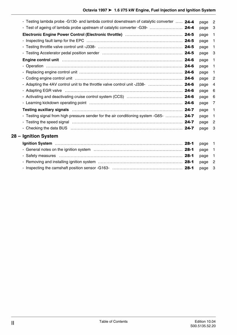
Supple-ment
Edition Subject Article Number
06.01 Basic Edition S00.5135.50.20
1 08.02 Changes for engine BFQ S00.5135.51.20
2 10.04 Modifications in Rep. Gr. 01 24 and 28 S00.5135.52.20

Octavia 1997 1.6 l/75 kW Engine, Fuel Injection and Ignition System
List of Supplements Edition 10.04
S00.5135.52.20

Octavia 1997 1.6 l/75 kW Engine, Fuel Injection and Ignition System
Table of ContentsEdition 10.04
S00.5135.52.20I
Table of Contents
01 – Self-diagnosis
Self-diagnosis I . . . . . . . . . . . . . . . . . . . . . . . . .. .............. ............... ............... ........ ...... .....
- Operation .. .............. . . . . . . . . . . . . . . .. .............. ............... ............... ........ ...... .....
- Technical data of self-diagnosis ...... .............. ............... ............... ........ ...... .....
- Connecting up the vehicle system tester -V.A.G 1552- and selecting the control unit for engine electronics ....... .......... . . . .. .............. ............... ............... ........ ...... .....
- Interrogating and erasing fault memory ........... ............... ............... ........ ...... .....
- Performing actuator diagnosis ........ .............. ............... ............... ........ ...... .....
Self-diagnosis II . . . . . . . . . . . . . . . . . . . . . . . . .. .............. ............... ............... ........ ...... .....
- Fault codes 16486 … 16990 .......... .............. ............... ............... ........ ...... .....
Self-diagnosis III . . . . . . . . . . . . . . . . . . . . . . . .. .............. ............... ............... ........ ...... .....
- Fault codes 17040 … 18088 .......... .............. ............... ............... ........ ...... .....
Self-diagnosis IV . . . . . . . . . . . . . . . . . . . . . . .. .............. ............... ............... ........ ...... .....
- Readiness code .......... ..... .. . . . . . . .. .............. ............... ............... ........ ...... .....
- Reading readiness code ............... .............. ............... ............... .............. .....
- Generating readiness code ........... .............. ............... ............... ........ ...... .....
Self-diagnosis V . . . . . . . . . . . . . . . . . . . . . . . .. .............. ............... ............... ........ ...... .....
- Reading measured value block ...... .............. ............... ............... ........ ...... .....
- Display groups 001 up to 028 ........ .............. ............... ............... ........ ...... .....
Self-diagnosis VI . . . . . . . . . . . . . . . . . . . . . . .. .............. ............... ............... ........ ...... .....
- Reading measured value block - display groups 030 to 132 ................ ........ ...... .....
24 – Fuel Formation, Injection
Fuel Injection System . . . . . . . . . . . . . . . . .. .............. ............... ............... ........ ...... .....
- Safety measures ......... ........ . . . . . .. .............. ............... ............... ........ ...... .....
- Rules of cleanliness ..... ........... . . .. .............. ............... ............... ........ ...... .....
- Overview of fitting locations ........... .............. ............... ............... ........ ...... .....
- General notes on the injection system ............ ............... ............... ........ ...... .....
- Removing and installing parts of the injection system ......... ............... ........ ...... .....
- Disassembling and assembling fuel distributor with injectors ............... .............. .....
- Disassembling and assembling top part of intake manifold ... ............... ........ ...... .....
- Disassembling and assembling the air filter ...... ............... ............... ........ ...... .....
- Resistances for intake air temperature sender -G42- ......... ............... ........ ...... .....
- Resistances for the coolant temperature sender -G62- ....... ............... ........ ...... .....
Testing components . . . . . . . . . . . . . . . . . . .. .............. ............... ............... ........ ...... .....
- Test wiring and components with Test box -V.A.G 1598/31- . ............... ........ ...... .....
- Inspecting the injection rate, tightness and jet formation of the injectors .. .............. .....
- Test fuel pressure regulator and holding pressure ............. ............... .............. .....
- Testing the intake system for tightness (unmetered air) ...... ............... ........ ...... .....
- Testing brake vacuum pump -V192- .............. ............... ............... .............. .....
Inspecting functions . . . . . . . . . . . . . . . . . . .. .............. ............... ............... ........ ...... .....
- Testing idling speed ..... ........... .. .. .............. ............... ............... ........ ...... .....
- Testing the intake manifold changeover .......... ............... ............... ........ ...... .....
Lambda control . . . . . . . . . . . . . . . . . . . . . . . . .. .............. ............... ............... ........ ...... .....
- Testing lambda probe -G39- and lambda control upstream of catalytic converter ..... .....
01-1 page 1
01-1 page 1
01-1 page 1
01-1 page 2
01-1 page 3
01-1 page 4
01-2 page 1
01-2 page 1
01-3 page 1
01-3 page 1
01-4 page 1
01-4 page 1
01-4 page 1
01-4 page 2
01-5 page 1
01-5 page 1
01-5 page 1
01-6 page 1
01-6 page 1
24-1 page 1
24-1 page 1
24-1 page 1
24-1 page 2
24-1 page 4
24-1 page 5
24-1 page 7
24-1 page 8
24-1 page 9
24-1 page 9
24-1 page 10
24-2 page 1
24-2 page 1
24-2 page 2
24-2 page 4
24-2 page 5
24-2 page 6
24-3 page 1
24-3 page 1
24-3 page 2
24-4 page 1
24-4 page 1
Octavia 1997 1.6 l/75 kW Engine, Fuel Injection and Ignition System
Table of Contents Edition 10.04
S00.5135.52.20II
- Testing lambda probe -G130- and lambda control downstream of catalytic converter .....
- Test of ageing of lambda probe upstream of catalytic converter -G39- ............ ........ ...
Electronic Engine Power Control (Electronic throttle) .............. ............... ...........
- Inspecting fault lamp for the EPC ............ .............. ............... ............... ........ ...
- Testing throttle valve control unit -J338- .... .............. ............... ............... ........ ...
- Testing Accelerator pedal position sender ............... ............... ............... ........ ...
Engine control unit . . . . . . . . . . . . . . . . . . . . . . . . . . . .. .............. ............... ............... ...........
- Operation .......... ....... .. . . . . . . . . . . . . . . . . . . . .. .............. ............... ............... ........ ...
- Replacing engine control unit .. ........... .. .. .............. ............... ............... ........ ...
- Coding engine control unit ..... .......... . . . .. .............. ............... ............... ........ ...
- Adapting the 4AV control unit to the throttle valve control unit -J338- ............. ........ ...
- Adapting EGR valve ............ ..... . . . . . . . . .. .............. ............... ............... ........ ...
- Activating and deactivating cruise control system (CCS) ............. ............... ...........
- Learning kickdown operating point .......... .............. ............... ............... ........ ...
Testing auxiliary signals . . . . . . . . . . . . . . . . . . . . .. .............. ............... ............... ........ ...
- Testing signal from high pressure sender for the air conditioning system -G65- ............
- Testing the speed signal ....... ......... . . . . .. .............. ............... ............... ........ ...
- Checking the data BUS ........ .......... . . . .. .............. ............... ............... ........ ...
28 – Ignition System
Ignition System . . . . . . . . . . . . . . . . . . . . . . . . . . . . . . . . .. .............. ............... ............... ........ ...
- General notes on the ignition system ....... .............. ............... ............... ........ ...
- Safety measures ................ .. . . . . . . . . . . . .. .............. ............... ............... ........ ...
- Removing and installing ignition system .... .............. ............... ............... ........ ...
- Inspecting the camshaft position sensor -G163- ........ ............... ............... ........ ...
24-4 page 2
24-4 page 3
24-5 page 1
24-5 page 1
24-5 page 1
24-5 page 3
24-6 page 1
24-6 page 1
24-6 page 1
24-6 page 2
24-6 page 4
24-6 page 6
24-6 page 6
24-6 page 7
24-7 page 1
24-7 page 1
24-7 page 2
24-7 page 3
28-1 page 1
28-1 page 1
28-1 page 1
28-1 page 2
28-1 page 3

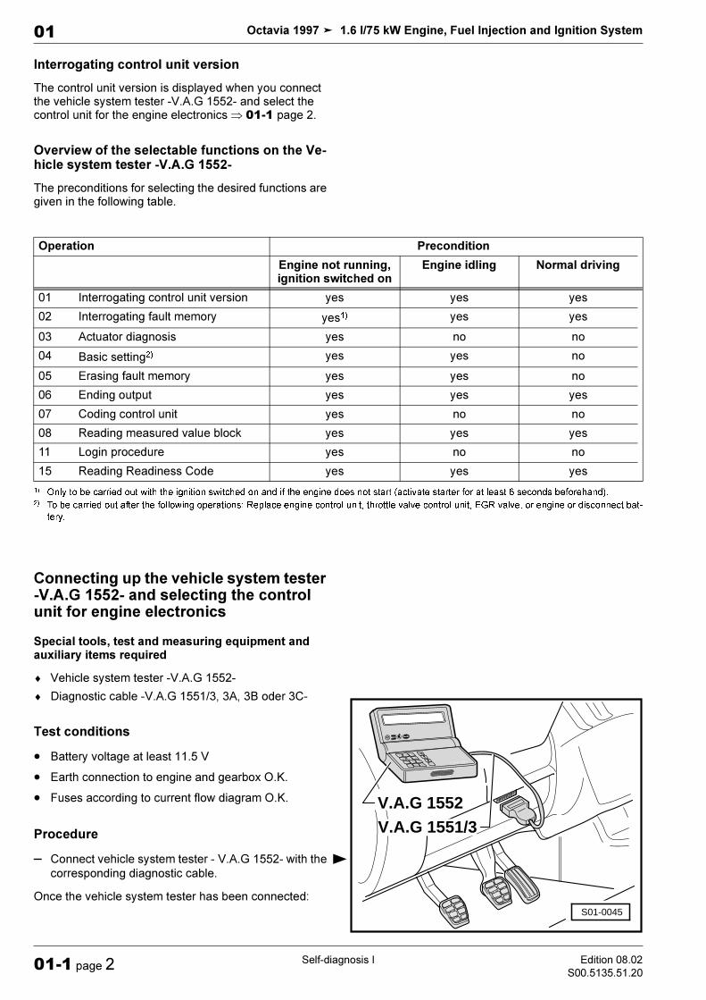
!" #"
$% ! ! ! " ! ! !# ! ! $!% ! & '()* )+ ! , " ! + - ! ./0 " - ! ./0 ./0 / $% $-% + - ! +
&' # #"($
! ) #"
*
*
% +,-./1 2 ! 34 & 5, ! ! !6 + + +78 !& !
%%% % - ! ! - ! ./0
%0#' 1 #',"' %",+2 3" - +
4$'' %",+2 3" '% #% %$ %($ 5 % %(% . ! ./0 1 + ./0 (" /" 9 :
& 9! - . +& 47 # 47
6%%; : - ! ./0 +
4 - ! + <
$% 6%%0'
*% %
- ! ! ! ! !
2QO\WREHFDUULHGRXWZLWKWKHLJQLWLRQVZLWFKHGRQDQGLIWKHHQJLQHGRHVQRWVWDUWDFWLYDWHVWDUWHUIRUDWOHDVWVHFRQGVEHIRUHKDQG
! ! / ! , 9
7REHFDUULHGRXWDIWHUWKHIROORZLQJRSHUDWLRQV5HSODFHHQJLQHFRQWUROXQLWWKURWWOHYDOYHFRQWUROXQLW(*5YDOYHRUHQJLQHRUGLVFRQQHFWEDW
WHU\
! ! ! ! ! 2 ! ! != : ! > - +8 ! ! ! 6 ! > > : ! ! !
V.A.G 1551/3
1552V.A.G.HELP
QOC
987
654
321
V.A.G 1552
S01-0045

;
! "# $ %
!& ' ( )(
> !<
%) $; ' *
- ! ./0 ! " < 2/?27 @ ) A $ - ) 6%
34 @ ! 2 (.@ 1 + -- !
@ + B @ +& @ + : @ : C: DDDDD @ C8 ; )> !<; # "
%%%# %> !<; ' !*
+ 'A * !
#%% # %%7 ! > !<; ' !*
*
*
!"#$%&&'()*%+)
,-
,-
%
,-.
,-
&
,
) &! ' &* '> !<; 2 ' * !
; >! ! +! + :
; 4 + -
+ ,-1 - + < +! : + + + <
' * + +!
; !
## %7; 2 ' * !
6%#% %C - <
*
'(/-.
*
# ! E= -- - A & -- A, .- -+ 8 - A2
! ! E??2 # .= .= . +8 .?
2QO\RQYHKLFOHVZLWKDQDXWRPDWLFJHDUER[
)
)
) ! )
) ( )
& # 47$ %($ 5 % %(% . ! ./0 1 + ./0 (" /" 9 :
6%%; : - ! ./0 ' *
; ' *> !< ! E= $! " ! ,% 8 & +!
. (/0) ! 8<; ! E=
; )> !< -- 8 & +! -- 8<; > - +8" ! =
: 2" ! -- - A
; )> !<
*
-*/-0-0'12
*
-*33,#3#,'45
-* 6-*-33'45
2
-- 8 & +! -- 8<; & -- A
> !< -- 8 & +! -- 8<; 8 - : ,> !< ! ! E?? + ! . +! ! ! E?? $ + % & + +! ! . <; ! .
> !< .= . + B & + +! / " & +! <; .= . 2 (=8C " 3 : F > 0 ?
> !< +8 - .? +! +8 - E, $ + % & +! +8 - .? <; +8 - .? : ,> !<; 2 ' * !
;
-*#7,*333'4&
-*0-0'1%
-*)-8/9
-*-973-
-* 4:

Octavia 1997 1.6 l/75 kW Engine, Fuel Injection and Ignition System
Self-diagnosis IIEdition 10.04
S00.5135.52.2001-2 page 1
01
01-2 Self-diagnosis II
Fault codes 16486 … 16990
♦ The fault table is arranged according to the 5-digit fault code on the left.
♦ The SAE code which is displayed on the right next to the fault code (e.g.. P0107) can be ignored (at present only valid for USA).
♦ Explanations regarding fault types (e.g. „open circuit or short-circuit to earth“) µ Operating instructions for the ve-hicle system tester.
♦ If parts are output as faulty: First check all cables and connectors to these components as well as the earth con-nections according to the Current Flow Diagram. Only if no fault is detected here should the part be replaced. This applies in particular if faults are shown as „sporadic“ (SP).
♦ If „literature“ appears in the display of the vehicle system tester -V.A.G 1552- look for the text required in the fault table under the fault code.
Readout on -V.A.G 1552- Rectifying fault
16486 Air mass meter -G70
Signal too low – Read measured value block, display group 002, display
field 4 µ Chap. 01-5.
– Test wiring and plug connections according to current
flow diagram.
– Testing intake system for leaks (unmetered air)
µ Chap. 24-2.
– Replace air filter if necessary µ Chap. 24-1.
16487 Air mass meter -G70
Signal too high
16496 Intake air temperature sender -G42
Signal too low – Read measured value block, display group 004, display
field 4 µ Chap. 01-5.
– Test resistances µ Chapter 24-1.
– Test wiring and plug connections according to current
flow diagram.
16497 Intake air temperature sender -G42
Signal too high
16500 Coolant temperature sender -G62
Implausible signal
– Read measured value block, display group 004, display
field 3 µ Chap. 01-5.
– Test resistances µ Chapter 24-1.
– Test wiring and plug connections according to current
flow diagram.
16501 Coolant temperature sender -G62
Signal too low
16502 Coolant temperature sender -G62
Signal too high
16514 Bank 1, probe 1
Electrical fault in the circuit
– Test lambda probe -G39- and lambda control upstream
of catalytic converter µ Chapter 24-4.
16515 Bank 1, probe 1
Voltage too low
16516 Bank 1, probe 1
Voltage too high
16517 Bank 1, probe 1
Signal too slow
16518 Bank 1, probe 1
No activity
16520 Bank 1, probe 2
Electrical fault in the circuit
– Test lambda probe -G130- and lambda control down-
stream of catalytic converter µ Chapter 24-4
Note
Octavia 1997 1.6 l/75 kW Engine, Fuel Injection and Ignition System
Self-diagnosis II Edition 10.04
S00.5135.52.2001-2 page 2
01
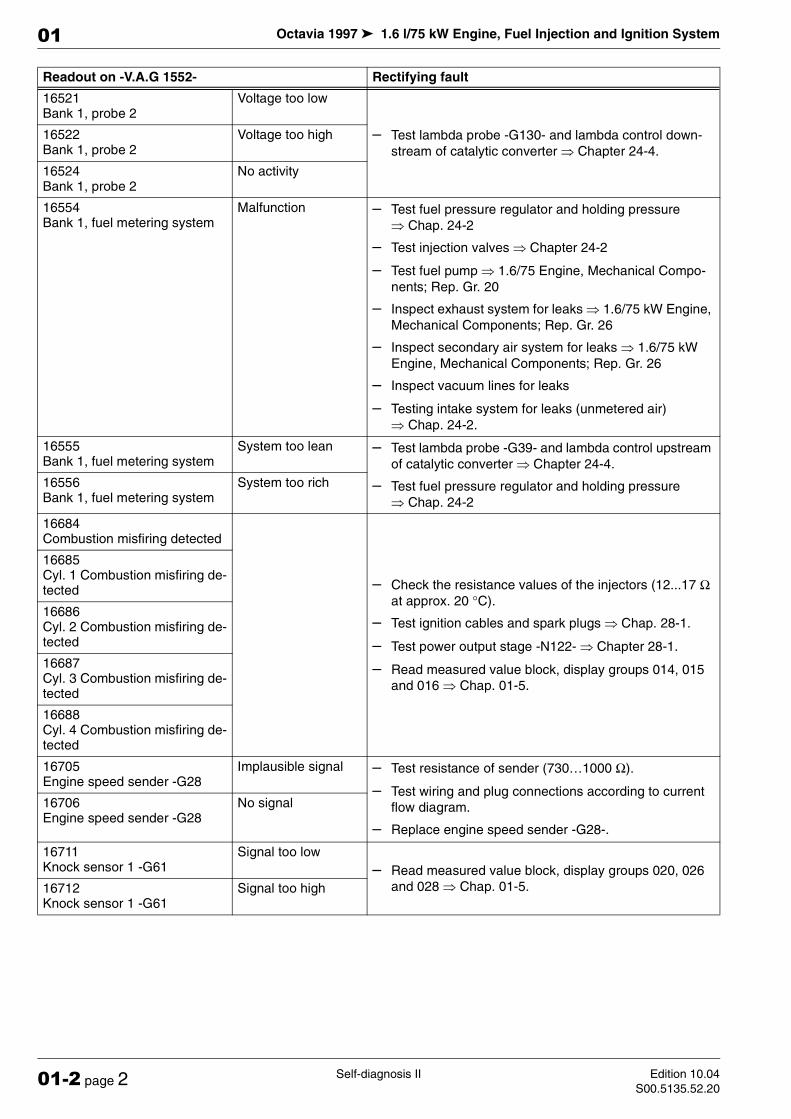
16521 Bank 1, probe 2
Voltage too low
– Test lambda probe -G130- and lambda control down-
stream of catalytic converter µ Chapter 24-4.
16522 Bank 1, probe 2
Voltage too high
16524 Bank 1, probe 2
No activity
16554 Bank 1, fuel metering system
Malfunction – Test fuel pressure regulator and holding pressure
µ Chap. 24-2
– Test injection valves µ Chapter 24-2
– Test fuel pump µ 1.6/75 Engine, Mechanical Compo-
nents; Rep. Gr. 20
– Inspect exhaust system for leaks µ 1.6/75 kW Engine,
Mechanical Components; Rep. Gr. 26
– Inspect secondary air system for leaks µ 1.6/75 kW
Engine, Mechanical Components; Rep. Gr. 26
– Inspect vacuum lines for leaks
– Testing intake system for leaks (unmetered air)
µ Chap. 24-2.
16555 Bank 1, fuel metering system
System too lean – Test lambda probe -G39- and lambda control upstream
of catalytic converter µ Chapter 24-4.
– Test fuel pressure regulator and holding pressure
µ Chap. 24-2
16556 Bank 1, fuel metering system
System too rich
16684 Combustion misfiring detected
– Check the resistance values of the injectors (12...17 Ω
at approx. 20 °C).
– Test ignition cables and spark plugs µ Chap. 28-1.
– Test power output stage -N122- µ Chapter 28-1.
– Read measured value block, display groups 014, 015
and 016 µ Chap. 01-5.
16685 Cyl. 1 Combustion misfiring de-tected
16686 Cyl. 2 Combustion misfiring de-tected
16687 Cyl. 3 Combustion misfiring de-tected
16688 Cyl. 4 Combustion misfiring de-tected
16705 Engine speed sender -G28
Implausible signal – Test resistance of sender (730…1000 Ω).
– Test wiring and plug connections according to current
flow diagram.
– Replace engine speed sender -G28-.
16706 Engine speed sender -G28
No signal
16711 Knock sensor 1 -G61
Signal too low
– Read measured value block, display groups 020, 026
and 028 µ Chap. 01-5.16712 Knock sensor 1 -G61
Signal too high
Readout on -V.A.G 1552- Rectifying fault
Octavia 1997 1.6 l/75 kW Engine, Fuel Injection and Ignition System
Self-diagnosis IIEdition 10.04
S00.5135.52.2001-2 page 3
01
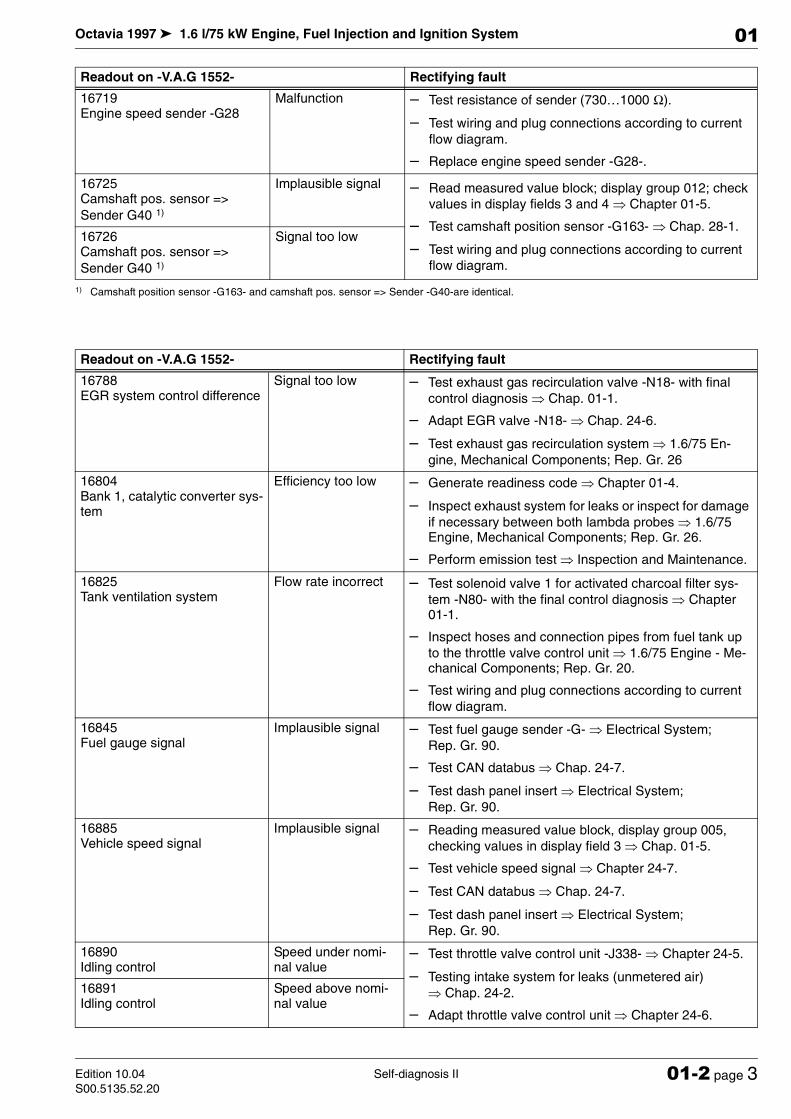
16719 Engine speed sender -G28
Malfunction – Test resistance of sender (730…1000 Ω).
– Test wiring and plug connections according to current
flow diagram.
– Replace engine speed sender -G28-.
16725 Camshaft pos. sensor =>
Sender G40 1)
Implausible signal – Read measured value block; display group 012; check
values in display fields 3 and 4 µ Chapter 01-5.
– Test camshaft position sensor -G163- µ Chap. 28-1.
– Test wiring and plug connections according to current
flow diagram.
16726 Camshaft pos. sensor =>
Sender G40 1)
Signal too low
1) Camshaft position sensor -G163- and camshaft pos. sensor => Sender -G40-are identical.
Readout on -V.A.G 1552- Rectifying fault
16788 EGR system control difference
Signal too low – Test exhaust gas recirculation valve -N18- with final
control diagnosis µ Chap. 01-1.
– Adapt EGR valve -N18- µ Chap. 24-6.
– Test exhaust gas recirculation system µ 1.6/75 En-
gine, Mechanical Components; Rep. Gr. 26
16804 Bank 1, catalytic converter sys-tem
Efficiency too low – Generate readiness code µ Chapter 01-4.
– Inspect exhaust system for leaks or inspect for damage
if necessary between both lambda probes µ 1.6/75 Engine, Mechanical Components; Rep. Gr. 26.
– Perform emission test µ Inspection and Maintenance.
16825 Tank ventilation system
Flow rate incorrect – Test solenoid valve 1 for activated charcoal filter sys-
tem -N80- with the final control diagnosis µ Chapter 01-1.
– Inspect hoses and connection pipes from fuel tank up
to the throttle valve control unit µ 1.6/75 Engine - Me-chanical Components; Rep. Gr. 20.
– Test wiring and plug connections according to current
flow diagram.
16845 Fuel gauge signal
Implausible signal – Test fuel gauge sender -G- µ Electrical System;
Rep. Gr. 90.
– Test CAN databus µ Chap. 24-7.
– Test dash panel insert µ Electrical System;
Rep. Gr. 90.
16885 Vehicle speed signal
Implausible signal – Reading measured value block, display group 005,
checking values in display field 3 µ Chap. 01-5.
– Test vehicle speed signal µ Chapter 24-7.
– Test CAN databus µ Chap. 24-7.
– Test dash panel insert µ Electrical System;
Rep. Gr. 90.
16890 Idling control
Speed under nomi-nal value
– Test throttle valve control unit -J338- µ Chapter 24-5.
– Testing intake system for leaks (unmetered air)
µ Chap. 24-2.
– Adapt throttle valve control unit µ Chapter 24-6.
16891 Idling control
Speed above nomi-nal value
Readout on -V.A.G 1552- Rectifying fault
Octavia 1997 1.6 l/75 kW Engine, Fuel Injection and Ignition System
Self-diagnosis II Edition 10.04
S00.5135.52.2001-2 page 4
01
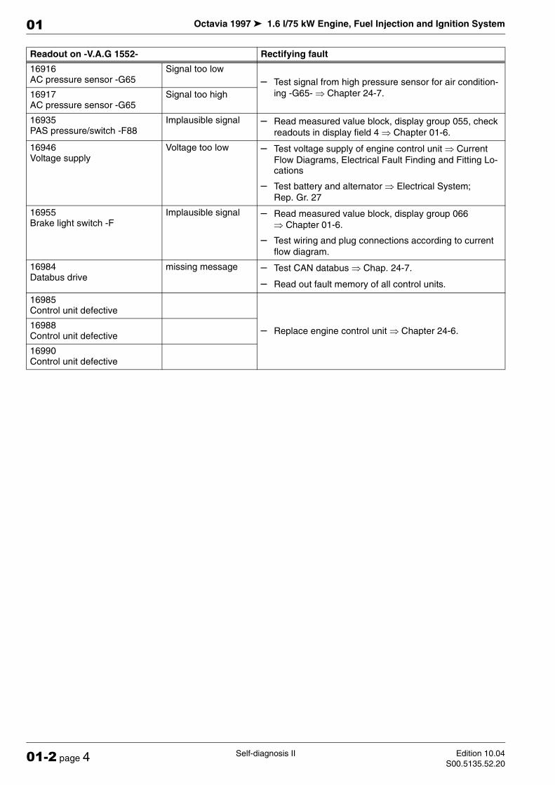
16916 AC pressure sensor -G65
Signal too low
– Test signal from high pressure sensor for air condition-
ing -G65- µ Chapter 24-7.16917 AC pressure sensor -G65
Signal too high
16935 PAS pressure/switch -F88
Implausible signal – Read measured value block, display group 055, check
readouts in display field 4 µ Chapter 01-6.
16946 Voltage supply
Voltage too low – Test voltage supply of engine control unit µ Current
Flow Diagrams, Electrical Fault Finding and Fitting Lo-cations
– Test battery and alternator µ Electrical System;
Rep. Gr. 27
16955 Brake light switch -F
Implausible signal – Read measured value block, display group 066
µ Chapter 01-6.
– Test wiring and plug connections according to current
flow diagram.
16984 Databus drive
missing message – Test CAN databus µ Chap. 24-7.
– Read out fault memory of all control units.
16985 Control unit defective
– Replace engine control unit µ Chapter 24-6.16988 Control unit defective
16990 Control unit defective
Readout on -V.A.G 1552- Rectifying fault

!"# $" !%!&'!''(")*+ ," ($$
! " # $% & '
! " # () " (# * +
, ! - * * '. *
$ , " ! - /
/ (# * +
0 /
(# * +
,
! - * * ' * / $ , "
! - / /
(# * +
! - * * '. * $ , "
! - / /
(# * +
0
(# * +
! - * * ' * / $ , "
! - / / 1
(# * +
0
. 2
* , ! # $ 3 4 "
! $ $ ,. -5 , '
*
! - ,, 6 " ! 78 ,, " 1
-5 , '
/
-5 , '
(# + * /
&
! - * * '. * $ , "
! - * * ' * / $ , "
! # $ # 3 4 "

1 8 $ 9
,
! - 8 3: ; "4! - /
/
1 8 $ 9
,
1 8 $ 9
,
1 8 $ 9
,
1 8 $ 9
! - 8 3: ; "4! - /
/
1 8 $ 9
1 8 $ 9
11 8 $ 9
1 8 $ 9
0
! - 8 3: ; "4! - /
/
11 8 $ 9
0
1 8 $ 9
0
1 8 $ 9
0
1 ,
/ ! - #! - ' $%
& ' .1. " '
+1 < #= > "% & ' .
1.. " '
/ +1 < #= > "% & ' .
- 1
0 +1 < #= > "% & ' .
- 1
,
+1 < #= > "% & ' .
- 1
+1 < #= > "% & ' .
?
& ;
! # $ 3 4 "
! "
?
& ;
1 (#+ @A '1
0 < ,
! '1 "
! - / /
(")*+ ," ($$

1 $
,
! - / 9 " ! - /
/
1 $
1 $
,
1 $
. " ,
! & " 1. " ,.1 " , &
7
! - 3: 4! $/ 1 < #= + >
"% & ' . ; ,, 9
! - '& ,, 9 "
; ,, 9
,
; $
"
-# , ,, 9
,
! - ,, , $ 9 "
(# + $ $
/ / ! - $ 8 $ 1 < #= + > "% & ' 1
! */ 1 < #= + > " % & ' 1
(# + $ $
2#
-# , ,, 9
! B "
-# , ,, 90
7 *# ,
,
! B " ! - *# , 5. "
1 7 *# ,
7 *# ,
0
$ $ 6..
,
! B " $ $ 6..
(")*+ ," ($$

; ,, 9
0 ! B "
'& '
! - /
/ '& '
/
.. $ 6
! B " .
$ 6 ,
. 2 C
* ! - * " / C+ 2
! 7" " / C+ 2
. 5* # , ,, 91
,
! B " ! - /
/
. 5* # , ,, 91
. 5* # , ,, 91
0
. > $ @A 6
! " # , $ $ 61 " / C+ 2
. " * ")
* ! $ * "
! - * $ ($ =#% & ' . -5 , '
* ! - ,, 6 " ! 78 ,, 6 "
1. -5 , '
/
. -5 , '
. - ,,
>! - ,, 6 " ! 78 ,, 6 "
1.11 - ,, , '1
.1 - ,, 6
*
. - ,, 6
), *
! - ,, 6 " ! - *$+ $ $%
& '
(")*+ ," ($$

. - ,, 6
(
! " # ,, ! - ,, 6 " .1
- ,, 6>
. " $ /
* ! & , *#+ $ 11 "
. *#
! 78 * $% & ' .1
! - * $% & ' .
:KHQDWWHPSWLQJWRVWDUWZLWKDQRQDGDSWHGNH\DVWDWLFIDXOWLVVWRUHGLQWKHPHPRU\,IDVXEVHTXHQWVWDUWDWWHPSWRFFXUVZLWKDQDGSDWHGNH\
WKHIDXOWLVFKDQJHGWRDVSRUDGLFIDXOW
(")*+ ," ($$ . - ,, 6
7 ! ,, 6 " / C+ 2
! 78 ,, " 1! - ,, 6 "
.. B '1
7KHVHIDXOWVDSSO\RQO\WRYHKLFOHVZLWKKHDWLQJV\VWHPRUPDQXDODLUFRQGLWLRQLQJ,IWKHVHIDXOWVDUHGLVSOD\HGRQYHKLFOHVILWWHGZLWK&OL
PDWURQLFSOHDVHFKHFNWKHFRGLQJRIWKHHQJLQHFRQWUROXQLWÜ &KDSWHU
! - / */ , / " / C+ 2
! - D+ 7 "% & '
.. B '1
0
5 $
5 / ! " # *$ $% & '
! 7" " / C+ 2
! &, " / C " / C+ 2
" ,
! & " 1
1
)DXOWLQFRQWUROXQLWVRIWZDUHZKDWLVPHDQWLVWKH3$6SUHVVXUHVZLWFK)
! & , *#+ $ + # $ "
(")*+ ," ($$

1
(")*+ ," ($$ " ,
! $ "
! - * $ ($ =#% & ' $
! " " 1
C* ,
* *; ")
! $ *; 7 '*;% & '
! " # " 1! " # () "
C, *
> *; ")
7 '.
/
! " .
7 '.
7 '
/
! "
7 '
C* ,
> * ")
! " # () " ! - * ($ /#% & '
< '.E'
* ! "
" ,
! & " 1
1 C* ,
, ! " # () "
C* ,
> 7( ")
! " # () " ! 7( 6 & '%
& ' C* ,
> *
! " # () " ! - $%
& ' .1 7 $ <
,
! & , *#+ $ "
1 &
,
! B " ! - * ,
" / C+ 2
1 &

1. &
,
! B " ! - * ,
" / C+ 2
&
F
,
! - B" F "
9* $ ,
! - ,, 6 " ! "
(")*+ ," ($$

Octavia 1997 1.6 l/75 kW Engine, Fuel Injection and Ignition System
Self-diagnosis IVEdition 10.04
S00.5135.52.2001-4 page 1
01
01-4 Self-diagnosis IV
Readiness code
Operation
The readiness code is an 8-digit numerical code that pro-vides information on the status of the emission-relevant diagnosis.
If the diagnosis for a system was successfully performed (e.g. diagnosis of catalytic converter), the relevant posi-tion of the numerical code is set from 1 to 0.
This diagnosis is performed at regular intervals during normal driving. If repairs have been done on a system rel-evant for the exhaust gas it is recommended to generate the readiness code as this guarantees that these systems operate according to the specifications. If a fault is detect-ed during diagnosis, it is then stored in the fault memory.
The readiness code is erased if the fault memory is erased or if there is an interruption to the voltage supply.
Reading readiness code
Special tools, test and measuring equipment and auxiliary items required
♦ Vehicle system tester -V.A.G 1552-
♦ Diagnostic cable -V.A.G 1551/3, 3A, 3B oder 3C-
Procedure
– Connect vehicle system tester -V.A.G 1552-. Switch
ignition on and select „address word“ 01 Engine elec-tronics µ Chap. 01-1.
– Function enter „readiness code“ and confirm
with .
The following readout must appear in the display after successfully completing all the checks:
– Press .
– Enter function „End output“ and confirm with .
Read-out on display:
Not all checks were performed successfully.
– Press .
– Generate readiness code µ 01-4 page 2.
1 5
Q
Readiness code ->
00000000 - Test complete
0 6 Q
Readiness code ->
00101101 - Test not complete

Octavia 1997 1.6 l/75 kW Engine, Fuel Injection and Ignition System
Self-diagnosis IV Edition 10.04
S00.5135.52.2001-4 page 2
01
Meaning of the 8-digit numerical block of the readiness code
Generating readiness code
Special tools, test and measuring equipment and auxiliary items required
♦ Vehicle system tester -V.A.G 1552-
♦ Diagnostic cable -V.A.G 1551/3, 3A, 3B oder 3C-
Test conditions
• Vehicle stopped.
• All electrical components such as lights and rear win-
dow heater must be switched off.
• On vehicles with an automatic gearbox the selector le-
ver must be in position „P“ or „N“.
• The coolant temperature must be at least 80°C
µ display group 004, display field 3.
• The intake air temperature must be below 60 °C µ
display group 004, display field 4.
Procedure
– Connect vehicle system tester -V.A.G 1552-. Start en-
gine and select „address word“ 01 Engine electronics µ Chapter 01-1.
Work step 1: Interrogating fault memory
– Enter address word „Interrogate fault memory“
and confirm with .
The number of stored faults or „No fault recognised“ ap-pears in the display.
If a fault is stored in the memory:
– Rectify the faults by referring to the fault table
µ Chapter 01-2 and 01-3.
If no fault is stored:
– Press .
X X X X X X X X Checked system
0 Exhaust gas recirculation
0 Lambda probe heater
0 Lambda probes
0 Air conditioning (no diagnosis at present/always 0)
0 Secondary air system
0 Activated charcoal filter (tank vent system)
0 Catalytic converter heater (no diagnosis at present/always 0)
0 Catalytic converter
0 2
Q
X faults detected

Octavia 1997 1.6 l/75 kW Engine, Fuel Injection and Ignition System
Self-diagnosis IVEdition 10.04
S00.5135.52.2001-4 page 3
01
Work step 2: Erasing fault memory
– Enter address word „Erase fault memory“ and
confirm with .
The readiness code is reset or erased each time the fault memory is erased.
Readout on display:
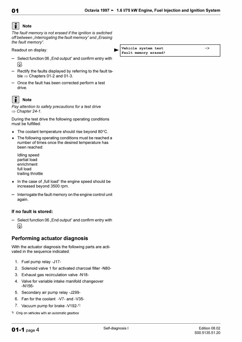
If the ignition is switched off during „Interrogating fault memory“ and „Erasing fault memory“, the fault memory is not erased.
– Press .
Work step 3: Diagnosis of secondary air injec-tion system
– Select function „initiate basic setting“ and con-
firm entry with .
Readout on display:
– for the „indicator group 077“ and confirm en-
try with .
Readout on display:
For engines with engine code BFQ
– Depress brake pedal and accelerator simultaneously.
For engines with engine code AVU
– Depress brake pedal and hold pressed.
Continued for all engines
Engine speed is increased and the readout in display field 4 switches from „Test OFF“ to „Test ON“.
– Run engine at high speed until specified value „Syst.
O.K.“ appears
If the display does not occur as described:
– Interrogate fault memory µ Chapter 01-1.
If the display occurs as described:
– Press .
Work step 4: Diagnosis of exhaust gas recircula-tion system
Readout on display:
– for the „indicator group 075“ and confirm en-
try with .
Readout on display:
0 5
Q
Note
Vehicle system test ->
The fault memory is erased
Note
0 4
Q
Initiating basic setting
Enter display group number XXX
0 7 7
Q
System in basic setting 77 ->
700 rpm 1.9 g/s 0.0 % Test ON
C
Initiating basic setting
Enter display group number XXX
0 7 5
QSystem in basic setting 75 ->
700 rpm 18.4 % -2.3 % System O.K.

Octavia 1997 1.6 l/75 kW Engine, Fuel Injection and Ignition System
Self-diagnosis IV Edition 10.04
S00.5135.52.2001-4 page 4
01
After initiating diagnosis of engine control unit the display in field 4 changes from „Test OFF“ to „Test ON“.
– Run engine at idling speed until „Syst. O.K.“ is dis-
played in display field 4.
If the display does not occur as described:
– Interrogate fault memory µ Chapter 01-1.
If the display occurs as described:
– Press .
Work step 5: Catalyst diagnosis
Readout on display:
– for the „indicator group 046“ and confirm en-
try with .
Readout on display:
For engines with engine code BFQ
– Depress brake pedal and accelerator simultaneously.
– Engine speed is increased and the readout in display
field 4 switches from „Test OFF“ to „Test ON“.
For engines with engine code AVU
– Set speed to 2500...4500 rpm. The readout in display
field 4 changes from „Test OFF“ to „Test ON“.
Continued for all engines
– Catalytic converter temperature in display field 2 must
be at least 400 °C.
This may take a few mlnutes.
– Maintain the speed until the readout in display field 4
shows the specified value „CatB1 O.K.“.
If the display does not occur as described:
– Interrogate fault memory µ Chapter 01-1.
No fault in the fault memory:
– Conduct a test drive at a constant speed.
– Pay attention to safety precautions for test drives
µ Chapter 24-1.
– Once again perform (test of conversion) diagnosis of
catalytic converter.
In case of equal result:
– Replace catalytic converter µ 1.6 l/75 kW Engine,
Mechanical Components; Rep. Gr. 26.
If the display occurs as described:
– Press .
C
Initiating basic setting
Enter display group number XXX
0 4 6
Q
System in basic setting 46 ->
700 rpm 250,0 C 0,96 Test OFF
Note
C
Octavia 1997 1.6 l/75 kW Engine, Fuel Injection and Ignition System
Self-diagnosis IVEdition 10.04
S00.5135.52.2001-4 page 5
01
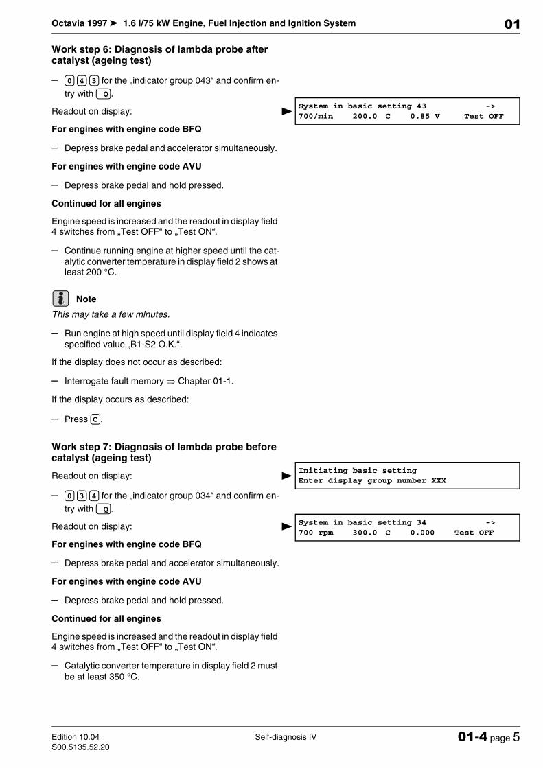
Work step 6: Diagnosis of lambda probe after catalyst (ageing test)
– for the „indicator group 043“ and confirm en-
try with .
Readout on display:
For engines with engine code BFQ
– Depress brake pedal and accelerator simultaneously.
For engines with engine code AVU
– Depress brake pedal and hold pressed.
Continued for all engines
Engine speed is increased and the readout in display field 4 switches from „Test OFF“ to „Test ON“.
– Continue running engine at higher speed until the cat-
alytic converter temperature in display field 2 shows at least 200 °C.
This may take a few mlnutes.
– Run engine at high speed until display field 4 indicates
specified value „B1-S2 O.K.“.
If the display does not occur as described:
– Interrogate fault memory µ Chapter 01-1.
If the display occurs as described:
– Press .
Work step 7: Diagnosis of lambda probe before catalyst (ageing test)
Readout on display:
– for the „indicator group 034“ and confirm en-
try with .
Readout on display:
For engines with engine code BFQ
– Depress brake pedal and accelerator simultaneously.
For engines with engine code AVU
– Depress brake pedal and hold pressed.
Continued for all engines
Engine speed is increased and the readout in display field 4 switches from „Test OFF“ to „Test ON“.
– Catalytic converter temperature in display field 2 must
be at least 350 °C.
0 4 3
Q
System in basic setting 43 ->
700/min 200.0 C 0.85 V Test OFF
Note
C
Initiating basic setting
Enter display group number XXX
0 3 4
Q
System in basic setting 34 ->
700 rpm 300.0 C 0.000 Test OFF

Octavia 1997 1.6 l/75 kW Engine, Fuel Injection and Ignition System
Self-diagnosis IV Edition 10.04
S00.5135.52.2001-4 page 6
01
This may take a few mlnutes.
– Run engine at high speed until display field 4 indicates
specified value „B1-S1 O.K.“.
If the display does not occur as described:
– Interrogate fault memory µ Chapter 01-1.
If the display occurs as described:
– Press .
Work step 8: Diagnosis of activated charcoal fil-ter system (tank vent system)
Readout on display:
– for the „indicator group 070“ and confirm en-
try with .
Readout on display:
After initiating diagnosis of engine control unit the display in field 4 changes from „Test OFF“ to „Test ON“.
– Run engine at idling speed until display field 4 indi-
cates specified value „TEV O.K.“.
If the display does not occur as described:
– Interrogate fault memory µ Chapter 01-1.
If the display occurs as described:
– Press .
– Read out readiness code µ 01-4 page 1.
Note
C
Initiating basic setting
Enter display group number XXX
0 7 0
Q
System in basic setting 70 ->
4.3 % 10.9 % -1.1 % Test OFF
Octavia 1997 1.6 l/75 kW Engine, Fuel Injection and Ignition System
Self-diagnosis VEdition 10.04
S00.5135.52.2001-5 page 1
01
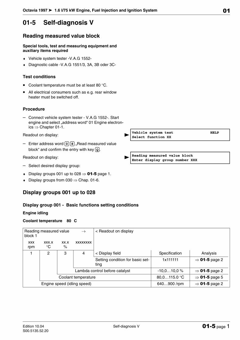
01-5 Self-diagnosis V
Reading measured value block
Special tools, test and measuring equipment and auxiliary items required
♦ Vehicle system tester -V.A.G 1552-
♦ Diagnostic cable -V.A.G 1551/3, 3A, 3B oder 3C-
Test conditions
• Coolant temperature must be at least 80 °C.
• All electrical consumers such as e.g. rear window
heater must be switched off.
Procedure
– Connect vehicle system tester - V.A.G 1552-. Start
engine and select „address word“ 01 Engine electron-ics µ Chapter 01-1.
Readout on display:
– Enter address word „Read measured value
block“ and confirm the entry with key .
Readout on display:
– Select desired display group:
♦ Display groups 001 up to 028 µ 01-5 page 1.
♦ Display groups from 030 µ Chap. 01-6.
Display groups 001 up to 028
Display group 001 - Basic functions setting conditions
Engine idling
Coolant temperature 80 C
Vehicle system test HELP
Select function XX
0 8
Q
Reading measured value block
Enter display group number XXX
Reading measured value block 1
→< Readout on display
xxx rpm
xxx.x °C
xx.x %
xxxxxxxx
1 2 3 4 < Display field Specification Analysis
Setting condition for basic set-ting
1x111111 µ 01-5 page 2
Lambda control before catalyst -10,0…10,0 % µ 01-5 page 2
Coolant temperature 80,0…115.0 °C µ 01-5 page 5
Engine speed (idling speed) 640…900 /rpm µ 01-5 page 2
Octavia 1997 1.6 l/75 kW Engine, Fuel Injection and Ignition System
Self-diagnosis V Edition 10.04
S00.5135.52.2001-5 page 2
01
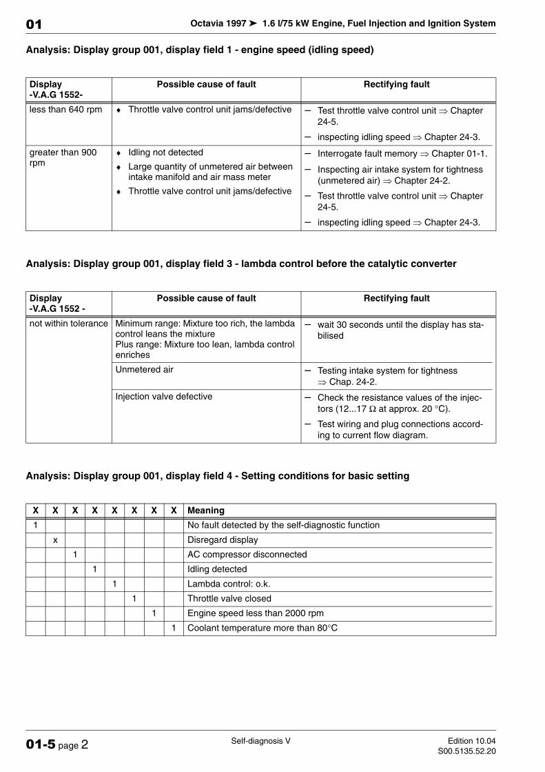
Analysis: Display group 001, display field 1 - engine speed (idling speed)
Analysis: Display group 001, display field 3 - lambda control before the catalytic converter
Analysis: Display group 001, display field 4 - Setting conditions for basic setting
Display -V.A.G 1552-
Possible cause of fault Rectifying fault
less than 640 rpm ♦ Throttle valve control unit jams/defective – Test throttle valve control unit µ Chapter
24-5.
– inspecting idling speed µ Chapter 24-3.
greater than 900 rpm
♦ Idling not detected
♦ Large quantity of unmetered air between intake manifold and air mass meter
♦ Throttle valve control unit jams/defective
– Interrogate fault memory µ Chapter 01-1.
– Inspecting air intake system for tightness
(unmetered air) µ Chapter 24-2.
– Test throttle valve control unit µ Chapter
24-5.
– inspecting idling speed µ Chapter 24-3.
Display -V.A.G 1552 -
Possible cause of fault Rectifying fault
not within tolerance Minimum range: Mixture too rich, the lambda control leans the mixture Plus range: Mixture too lean, lambda control enriches
– wait 30 seconds until the display has sta-
bilised
Unmetered air – Testing intake system for tightness
µ Chap. 24-2.
Injection valve defective – Check the resistance values of the injec-
tors (12...17 Ω at approx. 20 °C).
– Test wiring and plug connections accord-
ing to current flow diagram.
X X X X X X X X Meaning
1 No fault detected by the self-diagnostic function
x Disregard display
1 AC compressor disconnected
1 Idling detected
1 Lambda control: o.k.
1 Throttle valve closed
1 Engine speed less than 2000 rpm
1 Coolant temperature more than 80°C

Octavia 1997 1.6 l/75 kW Engine, Fuel Injection and Ignition System
Self-diagnosis VEdition 10.04
S00.5135.52.2001-5 page 3
01
Display group 002 Basic functions injection time, air mass meter
Engine idling
Coolant temperature 80 C
Analysis: Display group 002, display field 3 - injection time
Analysis: Display group 002, display field 4 - inducted air mass
Reading measured value block 2
→ < Readout on display
xxx rpm
xxx.x %
x.x ms
x.x g/s
1 2 3 4 < Display field Specification Analysis
Drawn in air mass 2,0…4.5 g/s µ 01-5 page 3
Injection period 2,0…4.0 ms µ 01-5 page 3
Engine load 15,0…35,0 % µ 01-5 page 7
Engine speed (idling speed) 640…900 /rpm µ 01-5 page 2
Display -V.A.G 1552 -
Possible cause of fault Rectifying fault
less than 2.0 ms ♦ high fuel volume from the activated char-coal filter system
♦ incorrect injection valve with too great flow rate fitted
– Test solenoid valve 1 for activated char-
coal filter system -N80- with the final con-trol diagnosis µ Chapter 01-1.
– Test injected quantity µ Chapter 24-2.
greater than 4.0 ms ♦ increased engine load due to electrical consumers (air conditioning system, fog lights etc.)
– Eliminate increased load (AC, fog lights
etc.).
Display -V.A.G 1552 -
Possible cause of fault Rectifying fault
less than 2.0 g/s ♦ Large quantity of unmetered air between intake manifold and air mass meter
– Eliminate unmetered air.
greater than 4.5 g/s ♦ Gear engaged (automatic gearbox) – Move selector lever into position „P“ or
„N“.
♦ Engine loaded by auxiliary equipment – Eliminate load (AC, power steering etc.).

Octavia 1997 1.6 l/75 kW Engine, Fuel Injection and Ignition System
Self-diagnosis V Edition 10.04
S00.5135.52.2001-5 page 4
01
Display group 003 Basic functions air mass meter, throttle valve angle
Engine idling
Coolant temperature 80 C
Analysis: Display group 003, display field 3 - throttle valve angle
Display group 004 Basic functions temperature
Engine idling
Coolant temperature 80 C
Reading measured value block 3
→ < Readout on display
xxx rpm
x.xx g/s
x.x %
xx.x ° b. TDC
1 2 3 4 < Display field Specification Analysis
Ignition angle 0,0…15.0° b. TDC ---
Throttle valve angle 1,5…4,0 % µ 01-5 page 4
Drawn in air mass 2,0…4.5 g/s µ 01-5 page 3
Engine speed (idling speed) 640…900 /rpm µ 01-5 page 2
Display -V.A.G 1552 -
Possible cause of fault Rectifying fault
greater than 4.0 % ♦ Engine control unit not adapted to throttle valve control unit
– Adapt engine control unit to throttle valve
control unit µ Chapter 24-6.
♦ Throttle valve potentiometer in throttle valve control unit faulty
– Test throttle valve control unit µ Chapter
24-5.
♦ Throttle valve jams – Remove fault.
Reading measured value block 4
→ < Readout on display
xxx rpm
xx.x V
xxx.x °C
xxx.x °C
1 2 3 4 < Display field Specification Analysis
Intake manifold temperature -38,0…80,0 °C µ 01-5 page 5
Coolant temperature 80,0…115.0 °C µ 01-5 page 5
Supply voltage of the engine control unit 12,5…14,5 V µ 01-5 page 5
Engine speed (idling speed) 640…900 /rpm µ 01-5 page 2

Octavia 1997 1.6 l/75 kW Engine, Fuel Injection and Ignition System
Self-diagnosis VEdition 10.04
S00.5135.52.2001-5 page 5
01
Analysis: Display group 004, display field 2 - supply voltage to the engine control unit
Analysis: Display group 004, display field 3 - coolant temperature
Analysis: Display group 004, display field 4 - intake air temperature
Display -V.A.G 1552 -
Possible cause of fault Rectifying fault
less than 12.5 V ♦ AC generator defective, battery heavily discharged
– Test alternator and battery voltage
µ Electrical System; Rep. Gr. 27.
♦ Battery heavily loaded just after start by a high charge current or by auxiliary equip-ment
– Increase engine speed slightly for a few
minutes and switch off additional consum-ers.
♦ Transition resistance in the power supply or earth connection for engine control unit
– Check the supply voltage of the engine
control unit µ Current Flow Diagrams, Electrical Fault Finding and Fitting Loca-tions.
♦ Current consumption with ignition off – Rectify any current drain.
greater than 14.5 V ♦ Voltage regulator on generator defective – Test voltage regulator, replace if neces-
sary µ Current Flow Diagrams, Electrical Fault Finding and Fitting Locations.
♦ Overvoltage due to starting aid or quick charger
– Interrogate fault memory µ Chapter 01-1.
Display -V.A.G 1552 -
Possible cause of fault Rectifying fault
less than 80,0 °C ♦ Engine too cold
♦ Coolant temperature sender or cable con-nection to engine control unit faulty
– Conduct road test if necessary.
– Test resistances µ Chapter 24-1.
greater than 115,0 °C
♦ Radiator dirty
♦ Radiator fan not operational
– Clean radiator.
– Perform actuator diagnosis µ Chapter 01-
1.
♦ Thermostat for map-controlled engine cooling system faulty
– Test thermostat for map-controlled engine
cooling system µ 1.6l/75 kW Engine, Me-chanical Components; Rep. Gr. 19.
♦ Coolant temperature sender or cable con-nection to engine control unit faulty
– Test resistances µ Chapter 24-1.
– Test wiring and plug connections accord-
ing to current flow diagram.
constant 30,0 or 49,5 °C
♦ Line interruption or short-circuit – Test wiring and plug connections to cool-
ant temperature sender -G62- according to current flow diagram.
Display -V.A.G 1552 -
Possible cause of fault Rectifying fault
constant 9.0 or 30.0 °C
♦ Line interruption, short-circuit to positive or earth
– Test resistances µ Chapter 24-1.
– Test wiring and plug connections to intake
air temperature sender -G42- according to current flow diagram.

Octavia 1997 1.6 l/75 kW Engine, Fuel Injection and Ignition System
Self-diagnosis V Edition 10.04
S00.5135.52.2001-5 page 6
01
Display group 005 Engine operating state
Engine idling
Coolant temperature 80 C
Display group 006 Basic functions altitude correction factor
Engine idling
Coolant temperature 80 C
Note on display field 3:
The overall temperature range is indicated as nominal value. The display value must be higher than the ambient tem-perature.
Note on display field 4:
Reading measured value block 5
→ < Readout on display
xxx rpm
xxx.x %
xxx km/h
Text
1 2 3 4 < Display field Specification Analysis
Operating condition (idling, partial load, enrichment, trail-ing throttle, full load)
Idling ---
Driving speed 0 km/h ---
Engine load 15,0…35,0 % µ 01-5 page 7
Engine speed (idling speed) 640…900 /rpm µ 01-5 page 2
Reading measured value block 6
→ < Readout on display
xxx rpm
xxx %
xxx.x °C
xx.x %
1 2 3 4 < Display field Specification Analysis
Level correction factor -50,0…10,0 % ---
Intake manifold temperature -38,0…80,0 °C µ 01-5 page 5
Engine load 15,0…35,0 % µ 01-5 page 7
Engine speed (idling speed) 640…900 /rpm µ 01-5 page 2
Altitude Readout
NN +5…-10
1000 m -5…-20
2000 m -10…-30

Octavia 1997 1.6 l/75 kW Engine, Fuel Injection and Ignition System
Self-diagnosis VEdition 10.04
S00.5135.52.2001-5 page 7
01
Display group 010 Ignition angle
Engine idling
Coolant temperature 80 C
Note on display field 3:
When accelerator fully depressed, the readout must be approx. 100 %.
Analysis: Display group 010, display field 2 - engine load
Analysis: Display group 010, display field 3 - throttle valve angle
Reading measured value block 10
→ < Readout on display
xxx rpm
xxx %
x.x %
xx.x ° b. TDC
1 2 3 4 < Display field Specification Analysis
Ignition angle 0,0…15.0° b. TDC ---
Throttle valve angle (potentiometer 1 -G187-)
1,5…4,0 % µ 01-5 page 7
Engine load 15,0…35,0 % µ 01-5 page 7
Engine speed (idling speed) 640…900 /rpm µ 01-5 page 2
Display -V.A.G 1552 -
Possible cause of fault Rectifying fault
less than 15.0 % ♦ lower value can only occur during trailing throttle driving
♦ Unmetered air – Testing intake system for tightness
µ Chap. 24-2.
greater than 35,0 %
♦ Poor idling (engine not running on all cyl-inders)
– Injector or spark plugs faulty.
♦ Electrical consumers on – Switch off electrical consumers.
♦ Steering wheel at limit stop – Turn steering wheel into middle position.
♦ Gear engaged (automatic gearbox) – Move selector lever into position „P“ or
„N“.
♦ Air mass meter faulty – Test wiring and plug connections to air
mass meter -G70- according to current flow diagram.
Display -V.A.G 1552 -
Possible cause of fault Rectifying fault
greater than 4.0 % ♦ Engine control unit not adapted to throttle valve control unit
– Adapt engine control unit to throttle valve
control unit µ Chapter 24-6.
♦ Throttle valve potentiometer in throttle valve control unit faulty
– Test throttle valve control unit µ Chapter
24-5.
♦ Throttle valve jams – Remove fault.

Octavia 1997 1.6 l/75 kW Engine, Fuel Injection and Ignition System
Self-diagnosis V Edition 10.04
S00.5135.52.2001-5 page 8
01
Display group 011 Ignition angle
Engine idling
Coolant temperature 80 C
Display group 012 Position of camshaft relative to crankshaft
Engine idling
Coolant temperature 80 C
Display group 014 Ignition misfiring recognition
Driving
Coolant temperature 80 C
Reading measured value block 11
→ < Readout on display
xxx rpm
xxx.x °C
xxx.x °C
xx.x ° b. TDC
1 2 3 4 < Display field Specification Analysis
Ignition angle 0,0…15.0° b. TDC ---
Intake manifold temperature -38,0…80,0 °C ---
Coolant temperature 80,0…115.0 °C µ 01-5 page 5
Engine speed (idling speed) 640…900 /rpm µ 01-5 page 2
Reading measured val-ue block 12
→ < Readout on display
xxx rpm
xxx.x %
xx xx
1 2 3 4 < Display field Specification Analysis
No. of crankshaft tooth at change of camshaft slope from high - low
86…90 ---
No. of crankshaft tooth at change of camshaft slope from low - high
26…30 ---
Engine load 15,0…35,0 % µ 01-5 page 7
Engine speed (idling speed) 640…900 /rpm µ 01-5 page 2
Reading measured value block 14
→ < Readout on display
xxxx rpm
xxx %
xxx Text
1 2 3 4 < Display field Specification Analysis
Misfiring detection (activated, deactivated)
activated ---
Sum of ignition misfiring x µ 01-5 page 10
Engine load 0,0…100,0 % ---
Engine speed (idling speed) 640…6500 /rpm ---
Octavia 1997 1.6 l/75 kW Engine, Fuel Injection and Ignition System
Self-diagnosis VEdition 10.04
S00.5135.52.2001-5 page 9
01
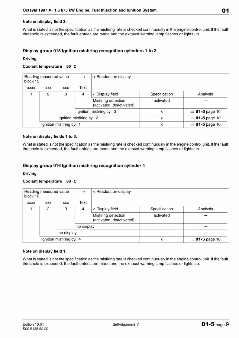
Note on display field 3:
What is stated is not the specification as the misfiring rate is checked continuously in the engine control unit. If the fault threshold is exceeded, the fault entries are made and the exhaust warning lamp flashes or lights up.
Display group 015 Ignition misfiring recognition cylinders 1 to 3
Driving
Coolant temperature 80 C
Note on display fields 1 to 3:
What is stated is not the specification as the misfiring rate is checked continuously in the engine control unit. If the fault threshold is exceeded, the fault entries are made and the exhaust warning lamp flashes or lights up.
Display group 016 Ignition misfiring recognition cylinder 4
Driving
Coolant temperature 80 C
Note on display field 1:
What is stated is not the specification as the misfiring rate is checked continuously in the engine control unit. If the fault threshold is exceeded, the fault entries are made and the exhaust warning lamp flashes or lights up.
Reading measured value block 15
→ < Readout on display
xxxx xxx xxx Text
1 2 3 4 < Display field Specification Analysis
Misfiring detection (activated, deactivated)
activated ---
Ignition misfiring cyl. 3 x µ 01-5 page 10
Ignition misfiring cyl. 2 x µ 01-5 page 10
Ignition misfiring cyl. 1 x µ 01-5 page 10
Reading measured value block 16
→ < Readout on display
xxxx xxx xxx Text
1 2 3 4 < Display field Specification Analysis
Misfiring detection (activated, deactivated)
activated ---
no display ---
no display ---
Ignition misfiring cyl. 4 x µ 01-5 page 10
Octavia 1997 1.6 l/75 kW Engine, Fuel Injection and Ignition System
Self-diagnosis V Edition 10.04
S00.5135.52.2001-5 page 10
01
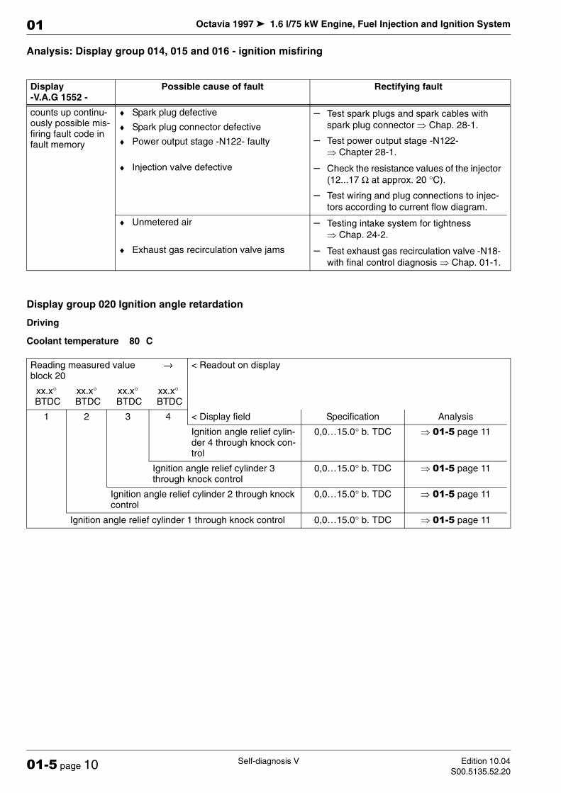
Analysis: Display group 014, 015 and 016 - ignition misfiring
Display group 020 Ignition angle retardation
Driving
Coolant temperature 80 C
Display -V.A.G 1552 -
Possible cause of fault Rectifying fault
counts up continu-ously possible mis-firing fault code in fault memory
♦ Spark plug defective
♦ Spark plug connector defective
♦ Power output stage -N122- faulty
– Test spark plugs and spark cables with
spark plug connector µ Chap. 28-1.
– Test power output stage -N122-
µ Chapter 28-1.
♦ Injection valve defective – Check the resistance values of the injector
(12...17 Ω at approx. 20 °C).
– Test wiring and plug connections to injec-
tors according to current flow diagram.
♦ Unmetered air – Testing intake system for tightness
µ Chap. 24-2.
♦ Exhaust gas recirculation valve jams – Test exhaust gas recirculation valve -N18-
with final control diagnosis µ Chap. 01-1.
Reading measured value block 20
→< Readout on display
xx.x° BTDC
xx.x° BTDC
xx.x° BTDC
xx.x° BTDC
1 2 3 4 < Display field Specification Analysis
Ignition angle relief cylin-der 4 through knock con-trol
0,0…15.0° b. TDC µ 01-5 page 11
Ignition angle relief cylinder 3 through knock control
0,0…15.0° b. TDC µ 01-5 page 11
Ignition angle relief cylinder 2 through knock control
0,0…15.0° b. TDC µ 01-5 page 11
Ignition angle relief cylinder 1 through knock control 0,0…15.0° b. TDC µ 01-5 page 11
Octavia 1997 1.6 l/75 kW Engine, Fuel Injection and Ignition System
Self-diagnosis VEdition 10.04
S00.5135.52.2001-5 page 11
01
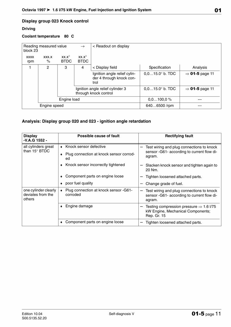
Display group 023 Knock control
Driving
Coolant temperature 80 C
Analysis: Display group 020 and 023 - ignition angle retardation
Reading measured value block 23
→ < Readout on display
xxxx rpm
xxx.x %
xx.x° BTDC
xx.x° BTDC
1 2 3 4 < Display field Specification Analysis
Ignition angle relief cylin-der 4 through knock con-trol
0,0…15.0° b. TDC µ 01-5 page 11
Ignition angle relief cylinder 3 through knock control
0,0…15.0° b. TDC µ 01-5 page 11
Engine load 0,0…100,0 % ---
Engine speed 640…6500 /rpm ---
Display -V.A.G 1552 -
Possible cause of fault Rectifying fault
all cylinders great than 15° BTDC
♦ Knock sensor defective
♦ Plug connection at knock sensor corrod-ed
– Test wiring and plug connections to knock
sensor -G61- according to current flow di-agram.
♦ Knock sensor incorrectly tightened – Slacken knock sensor and tighten again to
20 Nm.
♦ Component parts on engine loose – Tighten loosened attached parts.
♦ poor fuel quality – Change grade of fuel.
one cylinder clearly deviates from the others
♦ Plug connection at knock sensor -G61- corroded
– Test wiring and plug connections to knock
sensor -G61- according to current flow di-agram.
♦ Engine damage – Testing compression pressure µ 1.6 l/75
kW Engine, Mechanical Components; Rep. Gr. 15
♦ Component parts on engine loose – Tighten loosened attached parts.

Octavia 1997 1.6 l/75 kW Engine, Fuel Injection and Ignition System
Self-diagnosis V Edition 10.04
S00.5135.52.2001-5 page 12
01
Display group 026 Knock sensor voltage signal
Engine idling
Coolant temperature 80 C
Display group 028 Knock control
Mode basic setting 04
Driving
Coolant temperature 80 C
Reading measured value block 26
→ < Readout on display
x.xxx V
x.xxx V
x.xxx V
x.xxx V
1 2 3 4 < Display field Specification Analysis
Knock sensor voltage sig-nal cyl. 4
0,200…2 000 V ---
Knock sensor voltage signal cyl. 3 0,200…2,000 V ---
Knock sensor voltage signal cyl. 2 0,200…2,000 V ---
Knock sensor voltage signal cyl. 1 0,200…2,000 V ---
Reading measured value block 28
→ < Readout on display
xxx rpm
xxx.x %
xxx.x °C
Text
1 2 3 4 < Display field Specification Analysis
Result knock control (Test ON, Test OFF, Syst. O.K., Syst. N.O.K.)
Syst. o.k. ---
Coolant temperature 80,0…115.0 °C µ 01-5 page 5
Engine load 40…100 % ---
Engine speed 640…6500 /rpm ---
Octavia 1997 1.6 l/75 kW Engine, Fuel Injection and Ignition System
Self-diagnosis VIEdition 10.04
S00.5135.52.2001-6 page 1
01
01-6 Self-diagnosis VI
Reading measured value block - display groups 030 to 132
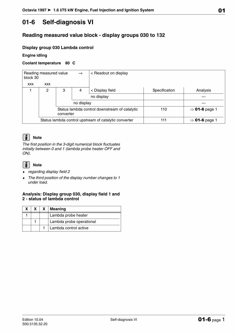
Display group 030 Lambda control
Engine idling
Coolant temperature 80 C
The first position in the 3-digit numerical block fluctuates initially between 0 and 1 (lambda probe heater OFF and ON).
♦ regarding display field 2
♦ The third position of the display number changes to 1 under load.
Analysis: Display group 030, display field 1 and 2 - status of lambda control
Reading measured value block 30
→< Readout on display
xxx xxx
1 2 3 4 < Display field Specification Analysis
no display ---
no display ---
Status lambda control downstream of catalytic converter
110 µ 01-6 page 1
Status lambda control upstream of catalytic converter 111 µ 01-6 page 1
Note
Note
X X X Meaning
1 Lambda probe heater
1 Lambda probe operational
1 Lambda control active

Octavia 1997 1.6 l/75 kW Engine, Fuel Injection and Ignition System
Self-diagnosis VI Edition 10.04
S00.5135.52.2001-6 page 2
01
Display group 031, lambda control - lambda values upstream of catalytic converter
Engine idling
Coolant temperature 80 C
Display group 032, lambda control - lambda learned values
Engine idling
Coolant temperature 80 C
♦ to the display fields 1 and 2:
♦ Low readouts indicate that the engine is running too rich and the lambda control therefore produces a leaner mix-ture.
♦ High readouts mean that the engine is running too lean and the lambda control therefore produces a richer mixture.
♦ add = additive - The effect of the fault (e.g. unmetered air) becomes increasingly less as engine speed rises. In the case of an additive initialisation value the injection period is changed by a fixed rate. This rate is independent of the basic injection period.
♦ mul = multiplicative - The effect of the fault (e.g. faulty injector) becomes greater as engine speed rises. The mul-tiplicative learned value is a percentage change in the injection period. This change is dependent on the basic in-jection period.
Reading measured value block 31
→< Readout on display
x.xxxx x.xxxx
1 2 3 4 < Display field Specification Analysis
no display ---
no display ---
Lambda nominal value - Bank 1 0,9900…1,0100 ---
Lambda actual value - Bank 1 0,9900…1,0100 ---
Reading measured value block 32
→< Readout on display
xx.x % xx.x %
1 2 3 4 < Display field Specification Analysis
no display ---
no display ---
Lambda learned value at part load (multiplica-tive)
-10,0…10,0 % µ 01-6 page 3
Lambda learned value at idling speed (additive) -14,0…14,0 % µ 01-6 page 3
Note
Octavia 1997 1.6 l/75 kW Engine, Fuel Injection and Ignition System
Self-diagnosis VIEdition 10.04
S00.5135.52.2001-6 page 3
01
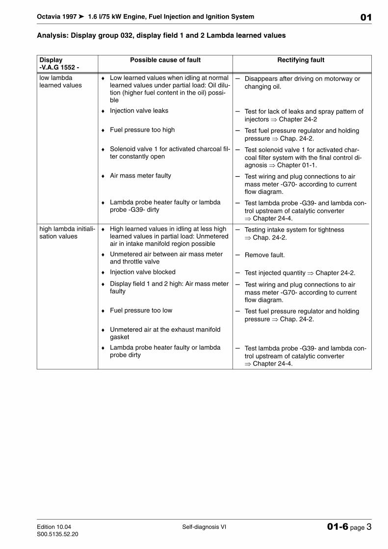
Analysis: Display group 032, display field 1 and 2 Lambda learned values
Display -V.A.G 1552 -
Possible cause of fault Rectifying fault
low lambda learned values
♦ Low learned values when idling at normal learned values under partial load: Oil dilu-tion (higher fuel content in the oil) possi-ble
– Disappears after driving on motorway or
changing oil.
♦ Injection valve leaks – Test for lack of leaks and spray pattern of
injectors µ Chapter 24-2
♦ Fuel pressure too high – Test fuel pressure regulator and holding
pressure µ Chap. 24-2.
♦ Solenoid valve 1 for activated charcoal fil-ter constantly open
– Test solenoid valve 1 for activated char-
coal filter system with the final control di-agnosis µ Chapter 01-1.
♦ Air mass meter faulty – Test wiring and plug connections to air
mass meter -G70- according to current flow diagram.
♦ Lambda probe heater faulty or lambda probe -G39- dirty
– Test lambda probe -G39- and lambda con-
trol upstream of catalytic converter µ Chapter 24-4.
high lambda initiali-sation values
♦ High learned values in idling at less high learned values in partial load: Unmetered air in intake manifold region possible
– Testing intake system for tightness
µ Chap. 24-2.
♦ Unmetered air between air mass meter and throttle valve
– Remove fault.
♦ Injection valve blocked – Test injected quantity µ Chapter 24-2.
♦ Display field 1 and 2 high: Air mass meter faulty
– Test wiring and plug connections to air
mass meter -G70- according to current flow diagram.
♦ Fuel pressure too low – Test fuel pressure regulator and holding
pressure µ Chap. 24-2.
♦ Unmetered air at the exhaust manifold gasket
♦ Lambda probe heater faulty or lambda probe dirty
– Test lambda probe -G39- and lambda con-
trol upstream of catalytic converter µ Chapter 24-4.

Octavia 1997 1.6 l/75 kW Engine, Fuel Injection and Ignition System
Self-diagnosis VI Edition 10.04
S00.5135.52.2001-6 page 4
01
Display group 033 Lambda control - Lambda probe upstream of catalytic converter
Engine idling
Coolant temperature 80 C
♦ Re display field 2:
♦ Voltage signal „Mixture rich“ (low level of residual ox-ygen) is between 0.130...1.500 V.
♦ Voltage signal „Mixture rich“ (high level of residual ox-ygen) is at approx. 1.500...4.800 V.
Analysis: Display group 033, display field 2 - lambda probe voltage upstream of catalytic converter
Reading measured value block 33
→< Readout on display
xx.x %
x.xx V
1 2 3 4 < Display field Specification Analysis
no display ---
no display ---
Lambda probe voltage before catalyst 1,40…1,60 V µ 01-6 page 4
Lambda control before catalyst -10,0…10,0 % µ Chapter 01-5
Note
Display field: 1 Rectifying fault
constant 0.000...1.400 V
or constant 1.600...3.600 V
– Testing lambda probe and lambda control upstream of catalytic con-
verter µ Chapter 24-4
constant 3,600 V
constant 0.000 V
Octavia 1997 1.6 l/75 kW Engine, Fuel Injection and Ignition System
Self-diagnosis VIEdition 10.04
S00.5135.52.2001-6 page 5
01
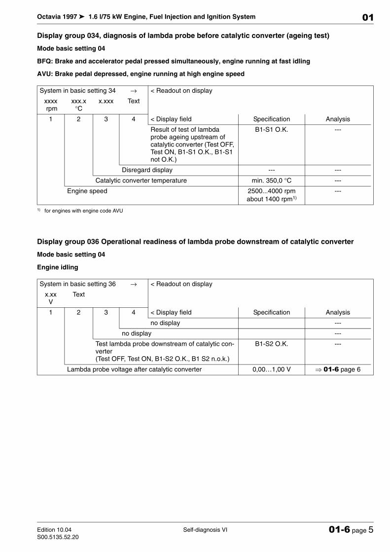
Display group 034, diagnosis of lambda probe before catalytic converter (ageing test)
Mode basic setting 04
BFQ: Brake and accelerator pedal pressed simultaneously, engine running at fast idling
AVU: Brake pedal depressed, engine running at high engine speed
Display group 036 Operational readiness of lambda probe downstream of catalytic converter
Mode basic setting 04
Engine idling
System in basic setting 34 → < Readout on display
xxxx rpm
xxx.x °C
x.xxx Text
1 2 3 4 < Display field Specification Analysis
Result of test of lambda probe ageing upstream of catalytic converter (Test OFF, Test ON, B1-S1 O.K., B1-S1 not O.K.)
B1-S1 O.K. ---
Disregard display --- ---
Catalytic converter temperature min. 350,0 °C ---
Engine speed 2500...4000 rpm
about 1400 rpm1)
1) for engines with engine code AVU
---
System in basic setting 36 → < Readout on display
x.xx V
Text
1 2 3 4 < Display field Specification Analysis
no display ---
no display ---
Test lambda probe downstream of catalytic con-verter (Test OFF, Test ON, B1-S2 O.K., B1 S2 n.o.k.)
B1-S2 O.K. ---
Lambda probe voltage after catalytic converter 0,00…1,00 V µ 01-6 page 6
Octavia 1997 1.6 l/75 kW Engine, Fuel Injection and Ignition System
Self-diagnosis VI Edition 10.04
S00.5135.52.2001-6 page 6
01
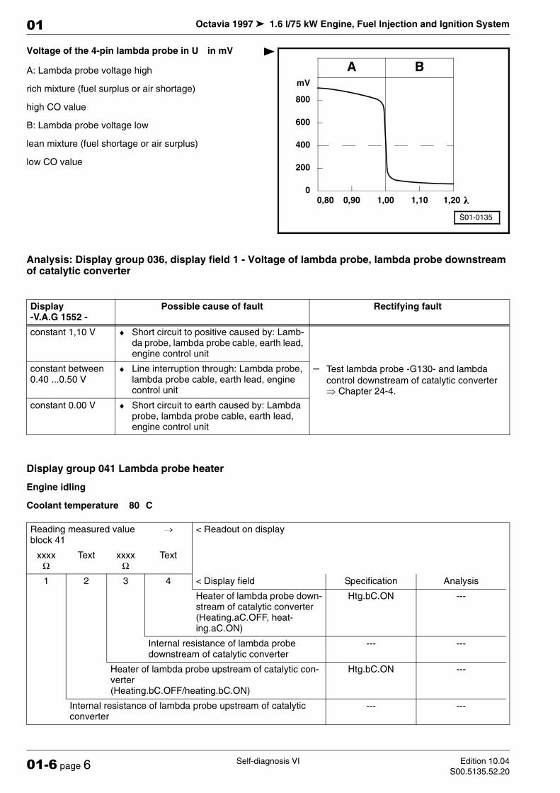
Voltage of the 4-pin lambda probe in U in mV
A: Lambda probe voltage high
rich mixture (fuel surplus or air shortage)
high CO value
B: Lambda probe voltage low
lean mixture (fuel shortage or air surplus)
low CO value
Analysis: Display group 036, display field 1 - Voltage of lambda probe, lambda probe downstream of catalytic converter
Display group 041 Lambda probe heater
Engine idling
Coolant temperature 80 C
Display -V.A.G 1552 -
Possible cause of fault Rectifying fault
constant 1,10 V ♦ Short circuit to positive caused by: Lamb-da probe, lambda probe cable, earth lead, engine control unit
– Test lambda probe -G130- and lambda
control downstream of catalytic converter µ Chapter 24-4.
constant between 0.40 ...0.50 V
♦ Line interruption through: Lambda probe, lambda probe cable, earth lead, engine control unit
constant 0.00 V ♦ Short circuit to earth caused by: Lambda probe, lambda probe cable, earth lead, engine control unit
Reading measured value block 41
→< Readout on display
xxxx Ω
Text xxxx Ω
Text
1 2 3 4 < Display field Specification Analysis
Heater of lambda probe down-stream of catalytic converter (Heating.aC.OFF, heat-ing.aC.ON)
Htg.bC.ON ---
Internal resistance of lambda probe downstream of catalytic converter
--- ---
Heater of lambda probe upstream of catalytic con-verter (Heating.bC.OFF/heating.bC.ON)
Htg.bC.ON ---
Internal resistance of lambda probe upstream of catalytic converter
--- ---
Octavia 1997 1.6 l/75 kW Engine, Fuel Injection and Ignition System
Self-diagnosis VIEdition 10.04
S00.5135.52.2001-6 page 7
01
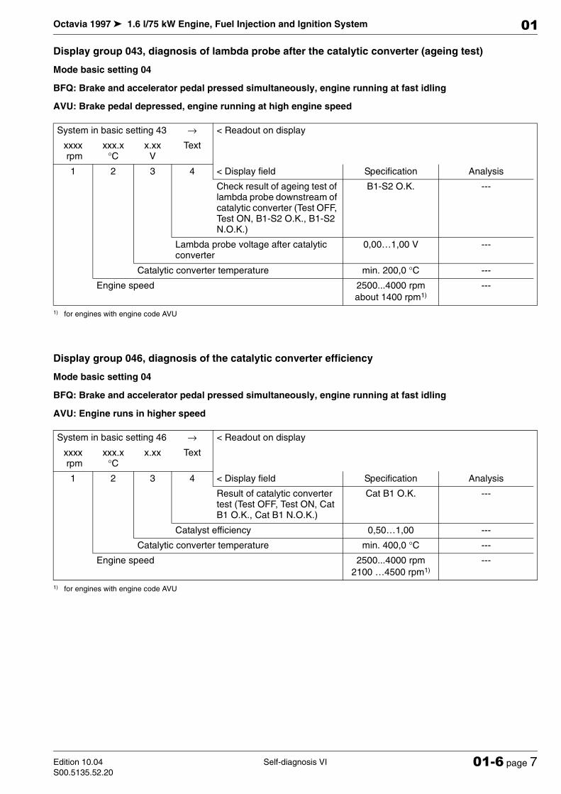
Display group 043, diagnosis of lambda probe after the catalytic converter (ageing test)
Mode basic setting 04
BFQ: Brake and accelerator pedal pressed simultaneously, engine running at fast idling
AVU: Brake pedal depressed, engine running at high engine speed
Display group 046, diagnosis of the catalytic converter efficiency
Mode basic setting 04
BFQ: Brake and accelerator pedal pressed simultaneously, engine running at fast idling
AVU: Engine runs in higher speed
System in basic setting 43 → < Readout on display
xxxx rpm
xxx.x °C
x.xx V
Text
1 2 3 4 < Display field Specification Analysis
Check result of ageing test of lambda probe downstream of catalytic converter (Test OFF, Test ON, B1-S2 O.K., B1-S2 N.O.K.)
B1-S2 O.K. ---
Lambda probe voltage after catalytic converter
0,00…1,00 V ---
Catalytic converter temperature min. 200,0 °C ---
Engine speed 2500...4000 rpm
about 1400 rpm1)
1) for engines with engine code AVU
---
System in basic setting 46 → < Readout on display
xxxx rpm
xxx.x °C
x.xx Text
1 2 3 4 < Display field Specification Analysis
Result of catalytic converter test (Test OFF, Test ON, Cat B1 O.K., Cat B1 N.O.K.)
Cat B1 O.K. ---
Catalyst efficiency 0,50…1,00 ---
Catalytic converter temperature min. 400,0 °C ---
Engine speed 2500...4000 rpm
2100 …4500 rpm1)
1) for engines with engine code AVU
---

Octavia 1997 1.6 l/75 kW Engine, Fuel Injection and Ignition System
Self-diagnosis VI Edition 10.04
S00.5135.52.2001-6 page 8
01
Display group 050 Engine speed increase when AC on
Engine idling
Coolant temperature 80 C
♦ Re display field 2:
♦ What is displayed is the specified engine speed (value computed internally in control unit in line with temperature) specified by the engine control unit.
♦ Re display field 4:
♦ On vehicles not fitted with air conditioning system „Compr. OFF“ is always displayed.
Display group 053 Engine speed increase with increased alternator load
Engine idling
Coolant temperature 80 C
♦ Re display field 4:
♦ The readout is dependent on the particular electrical components which are switched on, e.g. rear window heater, blower, seat heater etc.
Reading measured value block 50
→< Readout on display
xxx rpm
xxx rpm
Text Text
1 2 3 4 < Display field Specification Analysis
Operating state of AC com-pressor
Compr. ON or com-pr. OFF
---
Operating condition of air conditioning system
ON or OFF ---
Engine speed (idling speed - specified value) 640…900 /rpm ---
Engine speed (actual value) 640…900 /rpm µ Chapter 01-5
Note
Reading measured value block 53
→< Readout on display
xxxx rpm
xxxx rpm
xx.x V
xxx.x %
1 2 3 4 < Display field Specification Analysis
Alternator load 0,0…100,0 % ---
Supply voltage of the engine control unit
12,5…14,5 V µ Chapter 01-5
Engine speed (idling speed - specified value) approx. 640...900/rpm
---
Engine speed (actual value) 640…900 /rpm µ Chapter 01-5
Note

Octavia 1997 1.6 l/75 kW Engine, Fuel Injection and Ignition System
Self-diagnosis VIEdition 10.04
S00.5135.52.2001-6 page 9
01
Display group 054 Engine speed control
Driving
Coolant temperature 80 C
Display group 055 Idling speed stabilisation
Engine idling
Coolant temperature 80 C
♦ Re display field 3:
♦ The display shows to what extent the idling stabilizer has „disinitialised“ from the constructively given mean value. On a new engine the value is in the positive region because of the higher friction, on a run-in engine it is in the negative region.
Meaning of 5-digit numerical block
Reading measured value block 54
→< Readout on display
xxx rpm
Text xxx.x %
xxx.x %
1 2 3 4 < Display field Specification Analysis
Throttle valve angle (potenti-ometer 1 -G187-)
0,0…100,0 % ---
Sender 1 for accelerator pedal position 0,0…100,0 % ---
Operating condition (idling, partial load, enrich-ment, trailing throttle, full load)
--- ---
Engine speed 640…6500 /rpm ---
Reading measured value block 55
→< Readout on display
xxxx rpm
xx %
xx.x %
xxxxx
1 2 3 4 < Display field Specification Analysis
Operating conditions xxxxx µ 01-6 page 9
Initialisation value idle stabilizer -10,0…10,0 % ---
Idling regulator -10…20 % ---
Engine speed (idling speed) 640…900 /rpm µ Chapter 01-5
Note
X X X X X Meaning
1 PAS pressure switch ON (steering wheel at limit stop)
x no meaning
1 Air conditioning switched on
1 Gear engaged 1)
1 Air conditioning compressor on
1) Only on vehicles fitted with automatic gearbox
Octavia 1997 1.6 l/75 kW Engine, Fuel Injection and Ignition System
Self-diagnosis VI Edition 10.04
S00.5135.52.2001-6 page 10
01
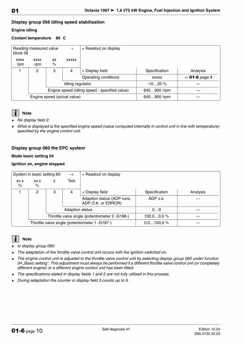
Display group 056 Idling speed stabilisation
Engine idling
Coolant temperature 80 C
♦ Re display field 2:
♦ What is displayed is the specified engine speed (value computed internally in control unit in line with temperature) specified by the engine control unit.
Display group 060 the EPC system
Mode basic setting 04
Ignition on, engine stopped
♦ to display group 060:
♦ The adaptation of the throttle valve control unit occurs with the ignition switched on.
♦ The engine control unit is adjusted to the throttle valve control unit by selecting display group 060 under function 04 „Basic setting“. This adjustment must always be performed if a different throttle valve control unit (or completely different engine) or a different engine control unit has been fitted.
♦ The specifications stated in display fields 1 and 2 are not fully utilised in this process.
♦ During adaptation the counter in display field 3 counts up to 9.
Reading measured value block 56
→< Readout on display
xxxx rpm
xxxx rpm
xx %
xxxxx
1 2 3 4 < Display field Specification Analysis
Operating conditions xxxxx µ 01-6 page 9
Idling regulator -10…20 % ---
Engine speed (idling speed - specified value) 640…900 /rpm ---
Engine speed (actual value) 640…900 /rpm ---
Note
System in basic setting 60→
< Readout on display
xx.x %
xx.x %
x Text
1 2 3 4 < Display field Specification Analysis
Adaption status (ADP runs, ADP O.K. or ERROR)
ADP o.k. ---
Adaption status 0…9 ---
Throttle valve angle (potentiometer 2 -G188-) 100,0…0,0 % ---
Throttle valve angle (potentiometer 1 -G187-) 0,0…100,0 % ---
Note

Octavia 1997 1.6 l/75 kW Engine, Fuel Injection and Ignition System
Self-diagnosis VIEdition 10.04
S00.5135.52.2001-6 page 11
01
Display group 062 Engine speed control EPC system
Ignition on, engine stopped
♦ to display group 062:
♦ The potentiometer on the throttle valve control unit and of the pedal value sensor are duplicated for safety reasons. The engine control unit constantly verifies the plausibility of the potentiometers.
♦ The value of sensor -2 for accelerator pedal position -G185- must always be half of the value of sender 1 for ac-celerator pedal position -G79-.
♦ The potentiometers of the throttle valve control unit contra-rotate. The value of both potentiometers together must always be approx. 100 %.
♦ The specifications stated are not fully utilised.
Display group 063 Kickdown adaptation
Only on vehicles fitted with automatic gearbox
Mode basic setting 04
Ignition on, engine stopped
♦ Re display field 4:
♦ If „actuated“ appears in display in the display field 4, depress the accelerator pedal fully and hold it in this position. The test is finished when „ADP O.K.“ appears in the display.
Reading measured value block 62
→< Readout on display
xx.x %
xx.x %
xx.x %
xx.x %
1 2 3 4 < Display field Specification Analysis
Sender 2 for accelerator pedal position -G185-
3,0…48,0 % ---
Sender 1 for accelerator pedal position -G79-
6,0…96,0 % ---
Throttle valve angle (potentiometer 2 -G188-) 97,0…3,0 % ---
Throttle valve angle (potentiometer 1 -G187-) 3,0…97,0 % ---
Note
System in basic setting 63→
< Readout on display
xx.x %
xx.x %
Text Text
1 2 3 4 < Display field Specification Analysis
Operating conditions (ER-ROR, actuated, ADP runs, ADP O.K.)
ADP o.k. µ Chapter 24-6
Kick-down switch Kickdown ---
Sender 2 for accelerator pedal position -G185- --- ---
Sender 1 for accelerator pedal position -G79- --- ---
Note
Octavia 1997 1.6 l/75 kW Engine, Fuel Injection and Ignition System
Self-diagnosis VI Edition 10.04
S00.5135.52.2001-6 page 12
01
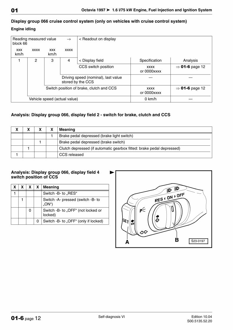
Display group 066 cruise control system (only on vehicles with cruise control system)
Engine idling
Analysis: Display group 066, display field 2 - switch for brake, clutch and CCS
Analysis: Display group 066, display field 4 switch position of CCS
Reading measured value block 66
→ < Readout on display
xxx km/h
xxxx xxx km/h
xxxx
1 2 3 4 < Display field Specification Analysis
CCS switch position xxxx or 0000xxxx
µ 01-6 page 12
Driving speed (nominal), last value stored by the CCS
--- ---
Switch position of brake, clutch and CCS xxxx or 0000xxxx
µ 01-6 page 12
Vehicle speed (actual value) 0 km/h ---
X X X X Meaning
1 Brake pedal depressed (brake light switch)
1 Brake pedal depressed (brake switch)
1 Clutch depressed (if automatic gearbox fitted: brake pedal depressed)
1 CCS released
X X X X Meaning
1 Switch -B- to „RES“
1 Switch -A- pressed (switch -B- to „ON“)
0 Switch -B- to „OFF“ (not locked or locked)
0 Switch -B- to „OFF“ (only if locked)

Octavia 1997 1.6 l/75 kW Engine, Fuel Injection and Ignition System
Self-diagnosis VIEdition 10.04
S00.5135.52.2001-6 page 13
01
Display group 070 Diagnosis of activated charcoal filter system (tank vent system)
Mode basic setting 04
Engine idling
Coolant temperature minimum 60 C
TVV means solenoid valve 1 for activated charcoal filter system. Diagnosis can only be initiated once each time the engine is started.
♦ Re display field 2:
♦ Lambda regulation - deviation in the negative range: activated charcoal filter full.
♦ Lambda regulation - deviation in the positive range: activated charcoal filter empty.
Display group 074 EGR positioner adaption
Mode basic setting 04
Ignition on, engine stopped
System in basic setting 70→< Readout on display
xxx.x %
xx.x %
xx.x %
Text
1 2 3 4 < Display field Specification Analysis
Result of diagnosis (Test ON, Test OFF, TVV O.K., TVV N.O.K.)
TVV o.k. ---
Idling speed controller variation during TVV diagnosis
-8,0…8,0 % ---
Lambda controller variation during TVV diagno-sis
-10,0…7,0 % ---
On/Off ratio of solenoid valve 1 for activated charcoal filter 0,0…100,0 % ---
Note
Note
System in basic setting 74→< Readout on display
x.x V
x.x V
xxx.x %
Text
1 2 3 4 < Display field Specification Analysis
Adaption status (ADP runs, ADP O.K. or ER-ROR)
ADP o.k. ---
Current poti value 0,0…100,0 % ---
Max. stop 3,0…4,8 V ---
Zero position 0,3…1.5 V ---
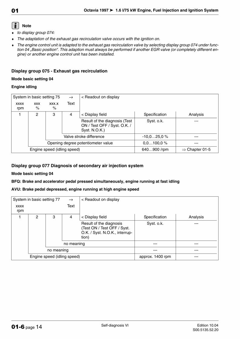
Octavia 1997 1.6 l/75 kW Engine, Fuel Injection and Ignition System
Self-diagnosis VI Edition 10.04
S00.5135.52.2001-6 page 14
01
♦ to display group 074:
♦ The adaptation of the exhaust gas recirculation valve occurs with the ignition on.
♦ The engine control unit is adapted to the exhaust gas recirculation valve by selecting display group 074 under func-tion 04 „Basic position“. This adaption must always be performed if another EGR valve (or completely different en-gine) or another engine control unit has been installed.
Display group 075 - Exhaust gas recirculation
Mode basic setting 04
Engine idling
Display group 077 Diagnosis of secondary air injection system
Mode basic setting 04
BFQ: Brake and accelerator pedal pressed simultaneously, engine running at fast idling
AVU: Brake pedal depressed, engine running at high engine speed
Note
System in basic setting 75→< Readout on display
xxxx rpm
xxx %
xxx.x %
Text
1 2 3 4 < Display field Specification Analysis
Result of the diagnosis (Test ON / Test OFF / Syst. O.K. / Syst. N.O.K.)
Syst. o.k. ---
Valve stroke difference -10,0…25,0 % ---
Opening degree potentiometer value 0,0…100,0 % ---
Engine speed (idling speed) 640…900 /rpm µ Chapter 01-5
System in basic setting 77→< Readout on display
xxxx rpm
Text
1 2 3 4 < Display field Specification Analysis
Result of the diagnosis (Test ON / Test OFF / Syst. O.K. / Syst. N.O.K., interrup-tion)
Syst. o.k. ---
no meaning --- ---
no meaning --- ---
Engine speed (idling speed) approx. 1400 rpm ---
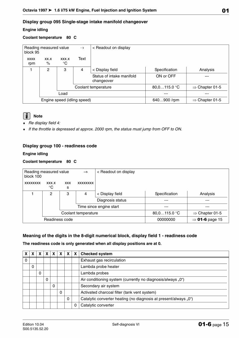
Octavia 1997 1.6 l/75 kW Engine, Fuel Injection and Ignition System
Self-diagnosis VIEdition 10.04
S00.5135.52.2001-6 page 15
01
Display group 095 Single-stage intake manifold changeover
Engine idling
Coolant temperature 80 C
♦ Re display field 4:
♦ If the throttle is depressed at approx. 2000 rpm, the status must jump from OFF to ON.
Display group 100 - readiness code
Engine idling
Coolant temperature 80 C
Meaning of the digits in the 8-digit numerical block, display field 1 - readiness code
The readiness code is only generated when all display positions are at 0.
Reading measured value block 95
→< Readout on display
xxxx rpm
xx.x %
xxx.x °C
Text
1 2 3 4 < Display field Specification Analysis
Status of intake manifold changeover
ON or OFF ---
Coolant temperature 80,0…115.0 °C µ Chapter 01-5
Load --- ---
Engine speed (idling speed) 640…900 /rpm µ Chapter 01-5
Note
Reading measured value block 100
→< Readout on display
xxxxxxxx xxx.x °C
xxx s
xxxxxxxx
1 2 3 4 < Display field Specification Analysis
Diagnosis status --- ---
Time since engine start --- ---
Coolant temperature 80,0…115.0 °C µ Chapter 01-5
Readiness code 00000000 µ 01-6 page 15
X X X X X X X X Checked system
0 Exhaust gas recirculation
0 Lambda probe heater
0 Lambda probes
0 Air conditioning system (currently no diagnosis/always „0“)
0 Secondary air system
0 Activated charcoal filter (tank vent system)
0 Catalytic converter heating (no diagnosis at present/always „0“)
0 Catalytic converter
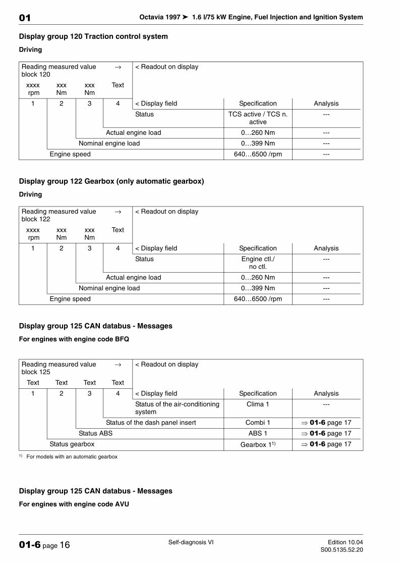
Octavia 1997 1.6 l/75 kW Engine, Fuel Injection and Ignition System
Self-diagnosis VI Edition 10.04
S00.5135.52.2001-6 page 16
01
Display group 120 Traction control system
Driving
Display group 122 Gearbox (only automatic gearbox)
Driving
Display group 125 CAN databus - Messages
For engines with engine code BFQ
Display group 125 CAN databus - Messages
For engines with engine code AVU
Reading measured value block 120
→ < Readout on display
xxxx rpm
xxx Nm
xxx Nm
Text
1 2 3 4 < Display field Specification Analysis
Status TCS active / TCS n. active
---
Actual engine load 0…260 Nm ---
Nominal engine load 0…399 Nm ---
Engine speed 640…6500 /rpm ---
Reading measured value block 122
→ < Readout on display
xxxx rpm
xxx Nm
xxx Nm
Text
1 2 3 4 < Display field Specification Analysis
Status Engine ctl./ no ctl.
---
Actual engine load 0…260 Nm ---
Nominal engine load 0…399 Nm ---
Engine speed 640…6500 /rpm ---
Reading measured value block 125
→ < Readout on display
Text Text Text Text
1 2 3 4 < Display field Specification Analysis
Status of the air-conditioning system
Clima 1 ---
Status of the dash panel insert Combi 1 µ 01-6 page 17
Status ABS ABS 1 µ 01-6 page 17
Status gearbox Gearbox 11)
1) For models with an automatic gearbox
µ 01-6 page 17
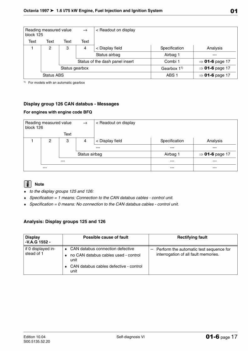
Octavia 1997 1.6 l/75 kW Engine, Fuel Injection and Ignition System
Self-diagnosis VIEdition 10.04
S00.5135.52.2001-6 page 17
01
Display group 126 CAN databus - Messages
For engines with engine code BFQ
♦ to the display groups 125 and 126:
♦ Specification = 1 means: Connection to the CAN databus cables - control unit.
♦ Specification = 0 means: No connection to the CAN databus cables - control unit.
Analysis: Display groups 125 and 126
Reading measured value block 125
→< Readout on display
Text Text Text Text
1 2 3 4 < Display field Specification Analysis
Status airbag Airbag 1 ---
Status of the dash panel insert Combi 1 µ 01-6 page 17
Status gearbox Gearbox 11)
1) For models with an automatic gearbox
µ 01-6 page 17
Status ABS ABS 1 µ 01-6 page 17
Reading measured value block 126
→< Readout on display
Text
1 2 3 4 < Display field Specification Analysis
--- --- ---
Status airbag Airbag 1 µ 01-6 page 17
--- --- ---
--- --- ---
Note
Display -V.A.G 1552 -
Possible cause of fault Rectifying fault
if 0 displayed in-stead of 1
♦ CAN databus connection defective
♦ no CAN databus cables used - control unit
♦ CAN databus cables defective - control unit
– Perform the automatic test sequence for
interrogation of all fault memories.

Octavia 1997 1.6 l/75 kW Engine, Fuel Injection and Ignition System
Self-diagnosis VI Edition 10.04
S00.5135.52.2001-6 page 18
01
Display group 130 Diagnosis of mapped cooling
Engine idling
AC switched off
♦ to the display fields 1 and 2:
♦ The coolant temperature at engine outlet must always be higher than at radiator outlet.
Display group 131 Diagnosis of mapped cooling
Engine idling
AC switched off
♦ to the display fields 1 and 3:
♦ The coolant temperature at engine outlet must always be higher than at radiator outlet.
Reading measured value block 130
→< Readout on display
xxx.x °C
xxx.x °C
xx.x %
Text
1 2 3 4 < Display field Specification Analysis
Result of the diagnosis (Test ON, Test OFF, Syst. O.K., Syst. N.O.K.)
Syst. o.k. ---
On/off ratio of thermostat 0…100 % ---
Coolant temperature radiator outlet 0…100 °C ---
Coolant temperature engine outlet 80…115 °C ---
Note
Reading measured value block 131
→< Readout on display
xxx.x °C
xxx.x °C
xxx.x %
xxx.x %
1 2 3 4 < Display field Specification Analysis
On/off ratio of thermostat 0,0…100,0 % ---
Coolant temperature radiator outlet 0,0…100,0 °C ---
Coolant temperature at engine outlet (specified temperature)
0,0…115.0 °C ---
Coolant temperature at engine outlet (specified tempera-ture)
80,0…115.0 °C ---
Note
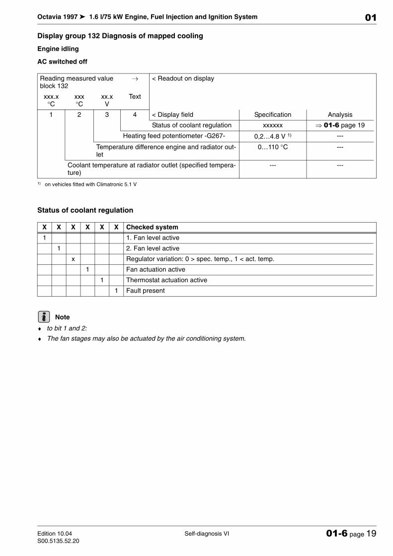
Octavia 1997 1.6 l/75 kW Engine, Fuel Injection and Ignition System
Self-diagnosis VIEdition 10.04
S00.5135.52.2001-6 page 19
01
Display group 132 Diagnosis of mapped cooling
Engine idling
AC switched off
Status of coolant regulation
♦ to bit 1 and 2:
♦ The fan stages may also be actuated by the air conditioning system.
Reading measured value block 132
→< Readout on display
xxx.x °C
xxx °C
xx.x V
Text
1 2 3 4 < Display field Specification Analysis
Status of coolant regulation xxxxxx µ 01-6 page 19
Heating feed potentiometer -G267- 0,2…4.8 V 1)
1) on vehicles fitted with Climatronic 5.1 V
---
Temperature difference engine and radiator out-let
0…110 °C ---
Coolant temperature at radiator outlet (specified tempera-ture)
--- ---
X X X X X X Checked system
1 1. Fan level active
1 2. Fan level active
x Regulator variation: 0 > spec. temp., 1 < act. temp.
1 Fan actuation active
1 Thermostat actuation active
1 Fault present
Note

Octavia 1997 1.6 l/75 kW Engine, Fuel Injection and Ignition System
Self-diagnosis VI Edition 10.04
S00.5135.52.2001-6 page 20
01
Octavia 1997 1.6 l/75 kW Engine, Fuel Injection and Ignition System
Fuel Injection SystemEdition 10.04
S00.5135.52.2024-1 page 1
24
24-1 Fuel Injection System
Safety measures
Observe the following points to prevent injury to persons and/or damage to the injection and preheating system:
♦ Do not touch or remove ignition leads with the engine running or at start speed.
♦ Ignition and plug connections must be switched off be-fore disconnecting and re-connecting cables of the fuel injection and ignition system as well as of test equipment.
♦ To operate the engine at start speed without it starting (e.g. for a testing compression pressure), unplug con-nectors from the ignition unit and connectors from the injectors. After performing the work interrogate fault memory and erase.
♦ Do not carry out engine wash unless the ignition is switched off.
♦ Switch off the ignition before disconnecting and con-necting the battery, as this may damage the 4AV con-trol unit.
If test and measuring devices are required during test drives observe the following:
♦ Always secure the test and measuring devices on the rear seat and have a second person operate them there. If the test and measuring equipment is operated from the front passenger seat, this can result in inju-ries to the persons sitting on that seat in the event of an accident which involves the front passenger airbag being deployed.
Rules of cleanliness
Pay careful attention to the following rules of cleanliness when working on the fuel supply or fuel injection systems:
♦ Thoroughly clean the connection points and their sur-roundings before releasing.
♦ Place removed parts on a clean surface and cover. Do not use fuzzy cloths!
♦ Carefully cover or close opened components if the re-pair is not completed immediately.
24 – Fuel Formation, Injection
Caution!
The fuel system is under pressure! Place a cloth around the connecting point before releasing hose connections or when opening the system. Then re-duce the pressure by carefully removing the hose or cap.

Octavia 1997 1.6 l/75 kW Engine, Fuel Injection and Ignition System
Fuel Injection System Edition 10.04
S00.5135.52.2024-1 page 2
24
♦ Only install clean parts: Remove spare parts from their wrapping immediately before fitting. Do not use any parts which have been stored unwrapped (e.g. in tool boxes etc.).
♦ When the system is open: avoid working with com-pressed air. Avoid moving the vehicle.
♦ Disconnected plug connections: Protect from dirt and moisture. Plug together only if dry.
Overview of fitting locations
♦ Components marked with an * are tested by self-diagnosis µ Chap. 01-1.
♦ Components marked with ** are tested by final control diagnosis µ Chapter 01-1.
1 - Activated charcoal filter sys-tem solenoid valve 1 -N80-*/**
resistance: 22…30 Ω
2 - Return-flow line
secure with spring strap clamps
to fuel delivery unit in fuel tank
3 - Feed line
secure with spring strap clamps
from fuel filter
4 - Camshaft position sensor -G163-*
for engines with engine code AVU
under top toothed belt guard
inspect µ Chapter 28-1
5 - Variable intake manifold changeover valve -N156- */**
inspect µ Chapter 24-3
6 - Top part of intake manifold
disassembling and assem-bling µ 24-1 page 8
7 - Bottom part of intake mani-fold
8 - Connector, 81 pin
only insert or remove plug when the ignition is switched off
unlock before removing
9 - Engine control unit*
Fitting location: in plenum chamber
replacing µ Chapter 24-6
10 - Connector, 40 pin
only insert or remove plug when the ignition is switched off
unlock before removing
11 - Throttle valve control unit -J338-*
inspect µ Chapter 24-5
6-pin connector
Note
B
AC
D
30
Octavia 1997 1.6 l/75 kW Engine, Fuel Injection and Ignition System
Fuel Injection SystemEdition 10.04
S00.5135.52.2024-1 page 3
24
contacts gold-plated
12 - Camshaft position sensor -G163-*
for engines with engine code BFQ
at rear of cylinder head
inspect µ Chapter 28-1
13 - EGR valve -N18- */**
with EGR potentiometer -G212-
6-pin connector
Adaptation µ Chap. 24-6
14 - Combination valve
Secondary air pump µ 1.6 l/75 kW Engine, Mechanical Components; Rep. Gr. 26
15 - Protective housing for relays and fuses
installation position:
♦ Secondary air injection pump relay -J299- */**
♦ Power supply of Simos engine control unit -J363-
only on vehicles fitted with automatic gearbox
♦ Fuse for brake vacuum pump -V192-
♦ Fuse for secondary air injection pump motor -V101-
16 - coolant temperature sender -G62-*
green
for engine control unit
with coolant temperature sender -G2-
resistances µ 24-1 page 10
17 - Brake vacuum pump -V192- with brake servo unit control unit -J542- (only on vehicles fitted with auto-matic gearbox) */**
inspect µ Chapter 24-2
18 - Air mass meter -G70- with intake air temperature sender -G42- *
contacts of sender and of connector gold-plated
resistances for intake air temperature sender -G42- µ 24-1 page 9
19 - Air filter
disassembling and assembling µ 24-1 page 9
20 - Power output stage -N122- with ignition coil -N, N128-
with identification for ignition leads, do not switch
resistances µ Chapter 28-1
21 - Engine speed sender -G28-*
resistance: 730…1000 Ω
22 - Injection valves -N30…N33-*
resistance: 12…17 Ω (at about 20 °C)
test injected quantity, leak tightness and spray pattern of injectors µ Chapter 24-2.
23 - Secondary air injection pump motor -V101- */**
Secondary air system: µ 1.6 l/75 kW Engine - Mechanical Components; Rep. Gr. 26
24 - Knock sensor I -G61-*
contacts of sender and of connector gold-plated
25 - Fuel pressure regulator
inspect µ Chapter 24-2
26 - 4-pin connector
Brown
for lambda probe heater -Z29- and lambda probe downstream of catalytic converter -G130-
on underside of vehicle on right
27 - Lambda probe downstream of catalytic converter -G130-, 50 Nm*
only coat thread with hot screw paste „G 052 112 A3“; the paste must not get into the slot of the probe body.
Test lambda probe -G130- and lambda control downstream of catalytic converter µ Chapter 24-4
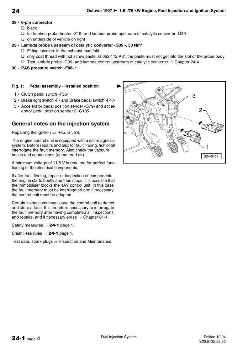
Octavia 1997 1.6 l/75 kW Engine, Fuel Injection and Ignition System
Fuel Injection System Edition 10.04
S00.5135.52.2024-1 page 4
24
28 - 6-pin connector
black
for lambda probe heater -Z19- and lambda probe upstream of catalytic converter -G39-
on underside of vehicle on right
29 - Lambda probe upstream of catalytic converter -G39 -, 50 Nm*
Fitting location: in the exhaust manifold
only coat thread with hot screw paste „G 052 112 A3“; the paste must not get into the slot of the probe body.
Test lambda probe -G39- and lambda control upstream of catalytic converter µ Chapter 24-4
30 - PAS pressure switch -F88- *
Fig. 1: Pedal assembly - installed position
1 - Clutch pedal switch -F36-
2 - Brake light switch -F- and Brake pedal switch -F47-
3 - Accelerator pedal position sender -G79- and accel-erator pedal position sender 2 -G185-
General notes on the injection system
Repairing the ignition µ Rep. Gr. 28.
The engine control unit is equipped with a self-diagnosis system. Before repairs and also for fault finding, first of all interrogate the fault memory. Also check the vacuum hoses and connections (unmetered air).
A minimum voltage of 11.5 V is required for perfect func-tioning of the electrical components.
If after fault finding, repair or inspection of components the engine starts briefly and then stops, it is possible that the immobiliser blocks the 4AV control unit. In this case the fault memory must be interrogated and if necessary the control unit must be adapted.
Certain inspections may cause the control unit to detect and store a fault. It is therefore necessary to interrogate the fault memory after having completed all inspections and repairs, and if necessary erase µ Chapter 01-1.
Safety measures µ 24-1 page 1.
Cleanliless rules µ 24-1 page 1.
Test data, spark plugs µ Inspection and Maintenance.
S24-0459
2
3
1
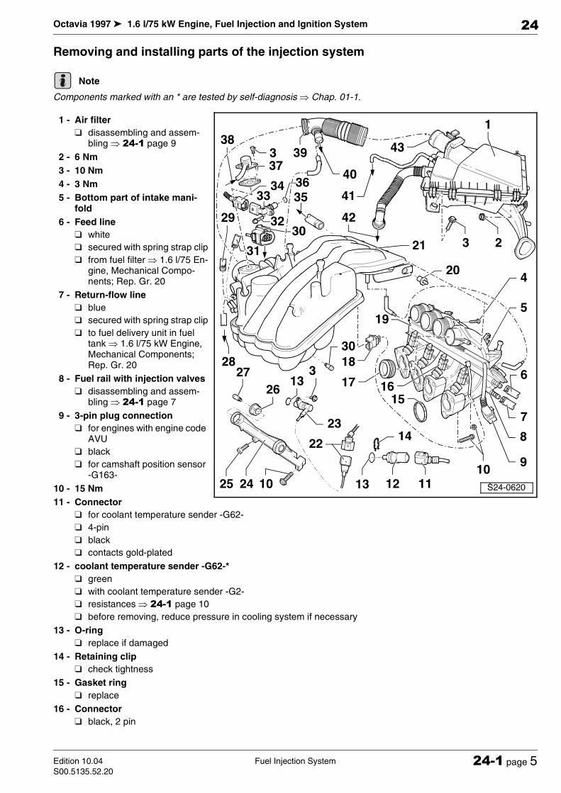
Octavia 1997 1.6 l/75 kW Engine, Fuel Injection and Ignition System
Fuel Injection SystemEdition 10.04
S00.5135.52.2024-1 page 5
24
Removing and installing parts of the injection system
Components marked with an * are tested by self-diagnosis µ Chap. 01-1.
1 - Air filter
disassembling and assem-bling µ 24-1 page 9
2 - 6 Nm
3 - 10 Nm
4 - 3 Nm
5 - Bottom part of intake mani-fold
6 - Feed line
white
secured with spring strap clip
from fuel filter µ 1.6 l/75 En-gine, Mechanical Compo-nents; Rep. Gr. 20
7 - Return-flow line
blue
secured with spring strap clip
to fuel delivery unit in fuel tank µ 1.6 l/75 kW Engine, Mechanical Components; Rep. Gr. 20
8 - Fuel rail with injection valves
disassembling and assem-bling µ 24-1 page 7
9 - 3-pin plug connection
for engines with engine code AVU
black
for camshaft position sensor -G163-
10 - 15 Nm
11 - Connector
for coolant temperature sender -G62-
4-pin
black
contacts gold-plated
12 - coolant temperature sender -G62-*
green
with coolant temperature sender -G2-
resistances µ 24-1 page 10
before removing, reduce pressure in cooling system if necessary
13 - O-ring
replace if damaged
14 - Retaining clip
check tightness
15 - Gasket ring
replace
16 - Connector
black, 2 pin
Note
Octavia 1997 1.6 l/75 kW Engine, Fuel Injection and Ignition System
Fuel Injection System Edition 10.04
S00.5135.52.2024-1 page 6
24
for injection valve -N30...N33-
17 - Gasket ring
18 - Connector
black, 2 pin
for variable intake manifold changeover valve -N156-
19 - Cable rail
20 - Body-bound rivet
21 - Top part of intake manifold
with variable intake manifold changeover
disassembling and assembling µ 24-1 page 8
22 - 3-pin plug connection
grey
for engine speed sender
Fitting location: close to dipstick
23 - Engine speed sender -G28-*
Resistance 730...1000 Ω
24 - Support
between intake manifold and cylinder head
25 - 8 Nm
for attaching vent connection
26 - Rubber bush
27 - 8 Nm
28 - To activated charcoal filter solenoid valve 1 -N80-
Activated charcoal filter µ 1.6 l/75 kW Engine, Mechanical Components; Rep. Gr. 20
29 - From heater feed
30 - Connector
6-pin
contacts gold-plated
for throttle valve control unit -J338-
31 - To T-connection and on to coolant expansion bottle
32 - 10 Nm
for engines with engine code BFQ
33 - Camshaft position sensor -G163-
for engines with engine code BFQ
inspect µ Chapter 28-1
34 - Connector
for engines with engine code BFQ
3-pin
for camshaft position sensor -G163-
35 - To the brake servo unit
36 - Gasket ring
for engines with engine code BFQ
replace if damaged
before fitting moisten with clean engine oil
37 - Gasket
replace
38 - From exhaust gas recirculation valve
39 - Air intake hose
with crankcase ventilation valve
with crankcase ventilation with heating resistor (only for models with optional equipment)
40 - For housing ventilation
41 - To EGR valve -N18-
clean air connection to fresh air supply
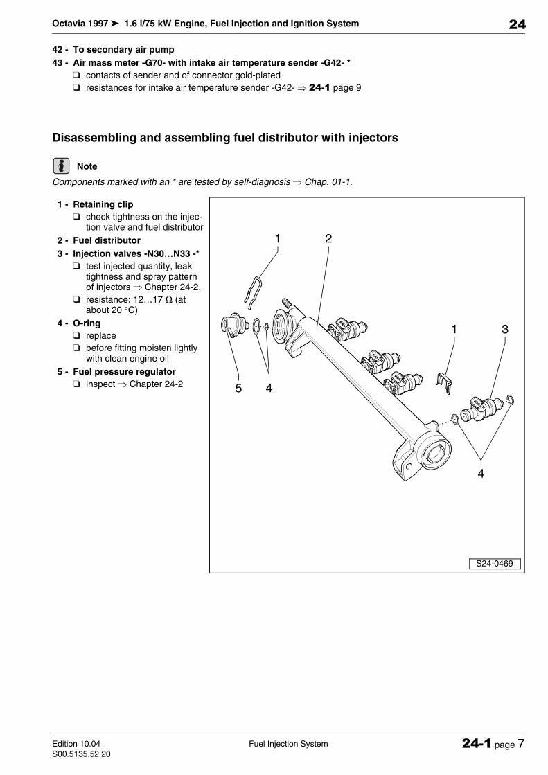
Octavia 1997 1.6 l/75 kW Engine, Fuel Injection and Ignition System
Fuel Injection SystemEdition 10.04
S00.5135.52.2024-1 page 7
24
42 - To secondary air pump
43 - Air mass meter -G70- with intake air temperature sender -G42- *
contacts of sender and of connector gold-plated
resistances for intake air temperature sender -G42- µ 24-1 page 9
Disassembling and assembling fuel distributor with injectors
Components marked with an * are tested by self-diagnosis µ Chap. 01-1.
1 - Retaining clip
check tightness on the injec-tion valve and fuel distributor
2 - Fuel distributor
3 - Injection valves -N30…N33 -*
test injected quantity, leak tightness and spray pattern of injectors µ Chapter 24-2.
resistance: 12…17 Ω (at about 20 °C)
4 - O-ring
replace
before fitting moisten lightly with clean engine oil
5 - Fuel pressure regulator
inspect µ Chapter 24-2
Note
S24-0469
1 2
1 3
4
45

Octavia 1997 1.6 l/75 kW Engine, Fuel Injection and Ignition System
Fuel Injection System Edition 10.04
S00.5135.52.2024-1 page 8
24
Disassembling and assembling top part of intake manifold
♦ Components marked with an * are tested by self-diagnosis µ Chap. 01-1.
♦ Components marked with ** are tested by final control diagnosis µ Chapter 01-1.
1 - 8 Nm
2 - Throttle valve control unit -J338-*
6-pin connector
contacts gold-plated
inspect µ Chapter 24-5
if replaced adapt engine con-trol unit µ Chapter 24-6
if replaced, adapt automatic gearbox control unit µ Automatic Gearbox; Rep. Gr. 01
3 - Gasket ring
replace
4 - Pressure relief valve
protects intake manifold from damage if excess pressure exists
5 - Top part of intake manifold
6 - Body-bound rivet
7 - Variable intake manifold changeover valve -N156- */**
inspect µ Chapter 24-3
Note

Octavia 1997 1.6 l/75 kW Engine, Fuel Injection and Ignition System
Fuel Injection SystemEdition 10.04
S00.5135.52.2024-1 page 9
24
Disassembling and assembling the air filter
Components marked with an * are tested by self-diagnosis µ Chap. 01-1.
1 - Air mass meter -G70- with in-take air temperature sender -G42- *
resistances for intake air temperature sender -G42- µ 24-1 page 9
2 - Gasket ring
3 - 6 Nm
4 - Air filter top part
5 - Filter insert
6 - 10 Nm
7 - Air filter bottom part
8 - Air deflector
9 - Air intake hose
for secondary air pump
10 - Ventilation hose
for exhaust gas recirculation valve
Resistances for intake air temperature sender -G42-
The nominal value in field -A- applies for temperature range 0...50 °C, nominal value in field -B- applies for tem-perature range 50...100 °C.
Read out examples:
♦ 30 °C is within the range -A- and equals a resistance of 1.5...2.0 kΩ.
♦ 80 °C is in range -B- and corresponds to a resistance of 275...375 Ω.
Note

Octavia 1997 1.6 l/75 kW Engine, Fuel Injection and Ignition System
Fuel Injection System Edition 10.04
S00.5135.52.2024-1 page 10
24
– Check resistance values of the intake manifold tem-
perature sender -G42- between contacts 2 + 4.
Resistances for the coolant temperature sender -G62-
The nominal value in field -A- applies for temperature range 0...50 °C, nominal value in field -B- applies for tem-perature range 50...100 °C.
Read out examples:
♦ 30 °C is within the range -A- and equals a resistance of 1500...2000 kΩ.
♦ 80 °C is in range -B- and corresponds to a resistance of 275...375 Ω.
– Test the resistance of the coolant temperature sender
-G62- between contacts C (signal) and D (earth).
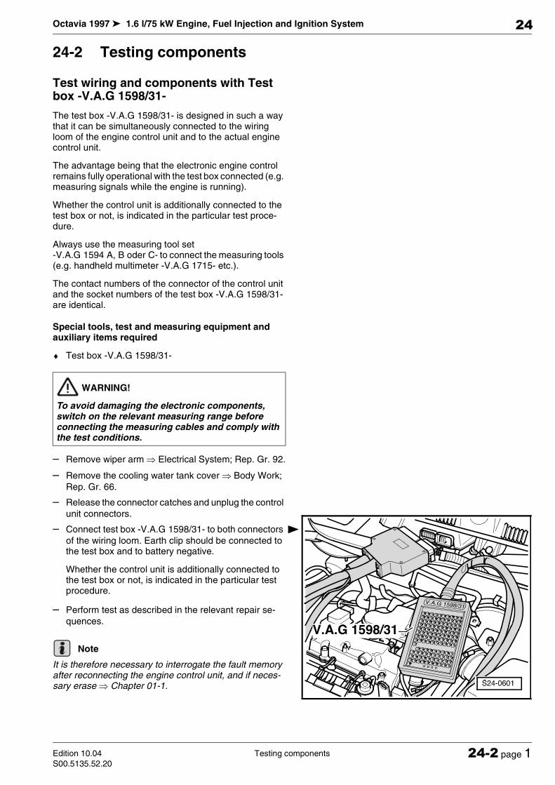
Octavia 1997 1.6 l/75 kW Engine, Fuel Injection and Ignition System
Testing componentsEdition 10.04
S00.5135.52.2024-2 page 1
24
24-2 Testing components
Test wiring and components with Test box -V.A.G 1598/31-
The test box -V.A.G 1598/31- is designed in such a way that it can be simultaneously connected to the wiring loom of the engine control unit and to the actual engine control unit.
The advantage being that the electronic engine control remains fully operational with the test box connected (e.g. measuring signals while the engine is running).
Whether the control unit is additionally connected to the test box or not, is indicated in the particular test proce-dure.
Always use the measuring tool set -V.A.G 1594 A, B oder C- to connect the measuring tools (e.g. handheld multimeter -V.A.G 1715- etc.).
The contact numbers of the connector of the control unit and the socket numbers of the test box -V.A.G 1598/31- are identical.
Special tools, test and measuring equipment and auxiliary items required
♦ Test box -V.A.G 1598/31-
– Remove wiper arm µ Electrical System; Rep. Gr. 92.
– Remove the cooling water tank cover µ Body Work;
Rep. Gr. 66.
– Release the connector catches and unplug the control
unit connectors.
– Connect test box -V.A.G 1598/31- to both connectors
of the wiring loom. Earth clip should be connected to the test box and to battery negative.
Whether the control unit is additionally connected to the test box or not, is indicated in the particular test procedure.
– Perform test as described in the relevant repair se-
quences.
It is therefore necessary to interrogate the fault memory after reconnecting the engine control unit, and if neces-sary erase µ Chapter 01-1.
WARNING!
To avoid damaging the electronic components, switch on the relevant measuring range before connecting the measuring cables and comply with the test conditions.
Note
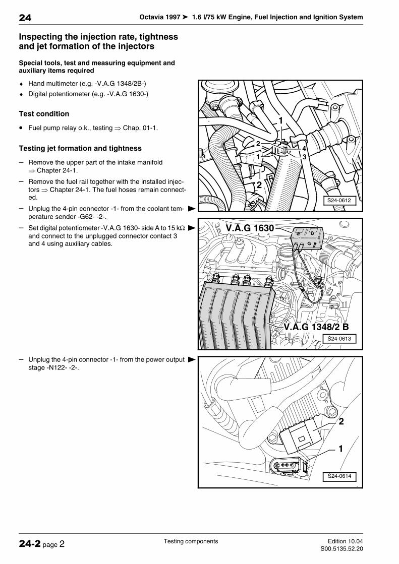
Octavia 1997 1.6 l/75 kW Engine, Fuel Injection and Ignition System
Testing components Edition 10.04
S00.5135.52.2024-2 page 2
24
Inspecting the injection rate, tightness and jet formation of the injectors
Special tools, test and measuring equipment and auxiliary items required
♦ Hand multimeter (e.g. -V.A.G 1348/2B-)
♦ Digital potentiometer (e.g. -V.A.G 1630-)
Test condition
• Fuel pump relay o.k., testing µ Chap. 01-1.
Testing jet formation and tightness
– Remove the upper part of the intake manifold
µ Chapter 24-1.
– Remove the fuel rail together with the installed injec-
tors µ Chapter 24-1. The fuel hoses remain connect-ed.
– Unplug the 4-pin connector -1- from the coolant tem-
perature sender -G62- -2-.
– Set digital potentiometer -V.A.G 1630- side A to 15 kΩ
and connect to the unplugged connector contact 3 and 4 using auxiliary cables.
– Unplug the 4-pin connector -1- from the power output
stage -N122- -2-.
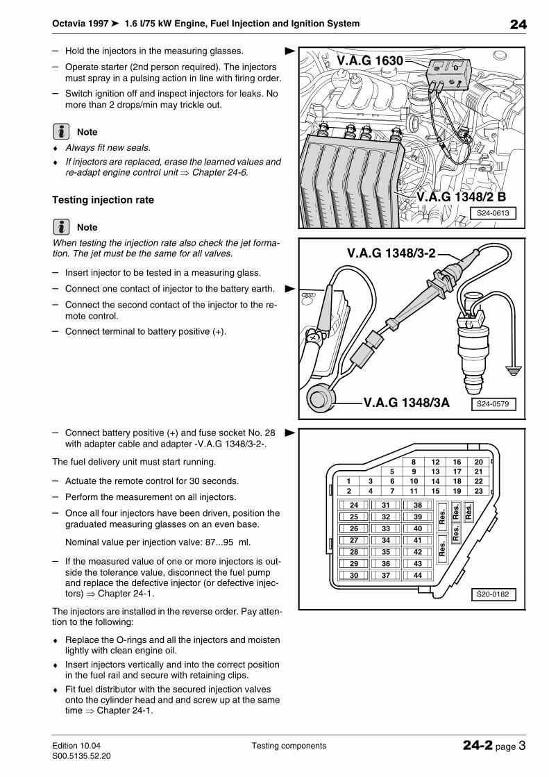
Octavia 1997 1.6 l/75 kW Engine, Fuel Injection and Ignition System
Testing componentsEdition 10.04
S00.5135.52.2024-2 page 3
24
– Hold the injectors in the measuring glasses.
– Operate starter (2nd person required). The injectors
must spray in a pulsing action in line with firing order.
– Switch ignition off and inspect injectors for leaks. No
more than 2 drops/min may trickle out.
♦ Always fit new seals.
♦ If injectors are replaced, erase the learned values and re-adapt engine control unit µ Chapter 24-6.
Testing injection rate
When testing the injection rate also check the jet forma-tion. The jet must be the same for all valves.
– Insert injector to be tested in a measuring glass.
– Connect one contact of injector to the battery earth.
– Connect the second contact of the injector to the re-
mote control.
– Connect terminal to battery positive (+).
– Connect battery positive (+) and fuse socket No. 28
with adapter cable and adapter -V.A.G 1348/3-2-.
The fuel delivery unit must start running.
– Actuate the remote control for 30 seconds.
– Perform the measurement on all injectors.
– Once all four injectors have been driven, position the
graduated measuring glasses on an even base.
Nominal value per injection valve: 87...95 ml.
– If the measured value of one or more injectors is out-
side the tolerance value, disconnect the fuel pump and replace the defective injector (or defective injec-tors) µ Chapter 24-1.
The injectors are installed in the reverse order. Pay atten-tion to the following:
♦ Replace the O-rings and all the injectors and moisten lightly with clean engine oil.
♦ Insert injectors vertically and into the correct position in the fuel rail and secure with retaining clips.
♦ Fit fuel distributor with the secured injection valves onto the cylinder head and and screw up at the same time µ Chapter 24-1.
Note
Note
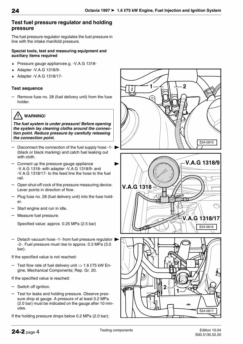
Octavia 1997 1.6 l/75 kW Engine, Fuel Injection and Ignition System
Testing components Edition 10.04
S00.5135.52.2024-2 page 4
24
Test fuel pressure regulator and holding pressure
The fuel pressure regulator regulates the fuel pressure in line with the intake manifold pressure.
Special tools, test and measuring equipment and auxiliary items required
♦ Pressure gauge appliancee.g. -V.A.G 1318-
♦ Adapter -V.A.G 1318/9-
♦ Adapter -V.A.G 1318/17-
Test sequence
– Remove fuse no. 28 (fuel delivery unit) from the fuse
holder.
– Disconnect the connection of the fuel supply hose -1-
(black or black marking) and catch fuel leaking out with cloth.
– Connect up the pressure gauge appliance
-V.A.G 1318- with adapter -V.A.G 1318/9- and -V.A.G 1318/17- to the feed line the hose to the fuel rail.
– Open shut-off cock of the pressure measuring device.
Lever points in direction of flow.
– Plug fuse no. 28 (fuel delivery unit) into the fuse hold-
er.
– Start engine and run in idle.
– Measure fuel pressure.
Specified value: approx. 0.25 MPa (2.5 bar)
– Detach vacuum hose -1- from fuel pressure regulator
-2-. Fuel pressure must rise to approx. 0.3 MPa (3.0 bar).
If the specified value is not reached:
– Test flow rate of fuel delivery unit µ 1.6 l/75 kW En-
gine, Mechanical Components; Rep. Gr. 20.
If the specified value is reached:
– Switch off ignition.
– Test for leaks and holding pressure. Observe pres-
sure drop at gauge. A pressure of at least 0.2 MPa (2.0 bar) must be indicated on the gauge after 10 min-utes.
If the holding pressure drops below 0.2 MPa (2.0 bar):
WARNING!
The fuel system is under pressure! Before opening the system lay cleaning cloths around the connec-tion point. Reduce pressure by carefully releasing the connection point.

Octavia 1997 1.6 l/75 kW Engine, Fuel Injection and Ignition System
Testing componentsEdition 10.04
S00.5135.52.2024-2 page 5
24
– Start engine and run in idle.
– After the pressure has been built up, switch ignition
off. Simultaneously connect the shut-off cock -arrow- to the pressure gauge appliance .
– Observe pressure drop at gauge.
If the pressure does not drop:
– Test non-return valve of fuel delivery unit µ 1.6 l/75
kW Engine, Mechanical Components; Rep. Gr. 20
If the pressure again drops:
– Inspect pressure measuring device for leaks.
– Inspect connections, O-rings on the fuel rail and injec-
tors for leaks.
If no leaks are found:
– Replace the fuel pressure regulator.
Before removing the pressure measuring device, place the cloth around the line connection and remove the fuse no. 28 (fuel delivery unit) from the fuse holder.
Testing the intake system for tightness (unmetered air)
Special tools, test and measuring equipment and auxiliary items required
♦ Vehicle system tester -V.A.G 1552-
♦ Diagnostic cable -V.A.G 1551/3, 3A, 3B, oder 3C-
♦ Engine leak search spray -G 001 800 A1-
Test condition
• Coolant temperature must be at least 80 °C.
Test sequence
♦ Because of the vacuum in the intake system the leak search spray is sucked in with the unmetered air. The leak search spray reduces the ignition performance of the mixture. This results in a drop in engine speed and a change in the lambda probe control value.
♦ You must comply with the safety instructions on the box.
– Connect vehicle system tester -V.A.G 1552-. Start en-
gine and select the address word 01 „Engine electron-ics“ µ Chapter 01-1.
– Enter function 08 „read measured value block“ and
select display group 001.
Readout on display:
Note
Note
Reading measured value block 1 ->
700/min 85.0 C 1.5 % 10111111
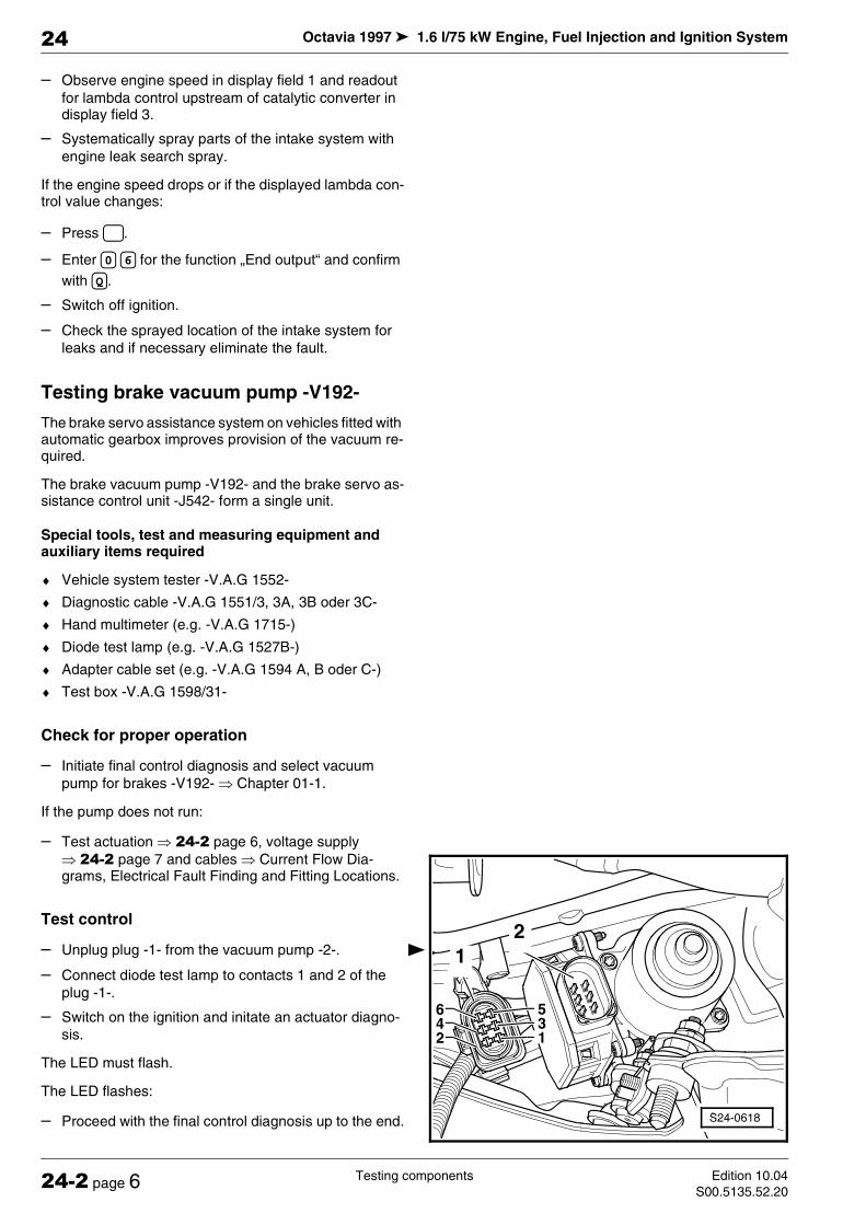
Octavia 1997 1.6 l/75 kW Engine, Fuel Injection and Ignition System
Testing components Edition 10.04
S00.5135.52.2024-2 page 6
24
– Observe engine speed in display field 1 and readout
for lambda control upstream of catalytic converter in display field 3.
– Systematically spray parts of the intake system with
engine leak search spray.
If the engine speed drops or if the displayed lambda con-trol value changes:
– Press .
– Enter for the function „End output“ and confirm
with .
– Switch off ignition.
– Check the sprayed location of the intake system for
leaks and if necessary eliminate the fault.
Testing brake vacuum pump -V192-
The brake servo assistance system on vehicles fitted with automatic gearbox improves provision of the vacuum re-quired.
The brake vacuum pump -V192- and the brake servo as-sistance control unit -J542- form a single unit.
Special tools, test and measuring equipment and auxiliary items required
♦ Vehicle system tester -V.A.G 1552-
♦ Diagnostic cable -V.A.G 1551/3, 3A, 3B oder 3C-
♦ Hand multimeter (e.g. -V.A.G 1715-)
♦ Diode test lamp (e.g. -V.A.G 1527B-)
♦ Adapter cable set (e.g. -V.A.G 1594 A, B oder C-)
♦ Test box -V.A.G 1598/31-
Check for proper operation
– Initiate final control diagnosis and select vacuum
pump for brakes -V192- µ Chapter 01-1.
If the pump does not run:
– Test actuation µ 24-2 page 6, voltage supply
µ 24-2 page 7 and cables µ Current Flow Dia-grams, Electrical Fault Finding and Fitting Locations.
Test control
– Unplug plug -1- from the vacuum pump -2-.
– Connect diode test lamp to contacts 1 and 2 of the
plug -1-.
– Switch on the ignition and initate an actuator diagno-
sis.
The LED must flash.
The LED flashes:
– Proceed with the final control diagnosis up to the end.
0 6
Q
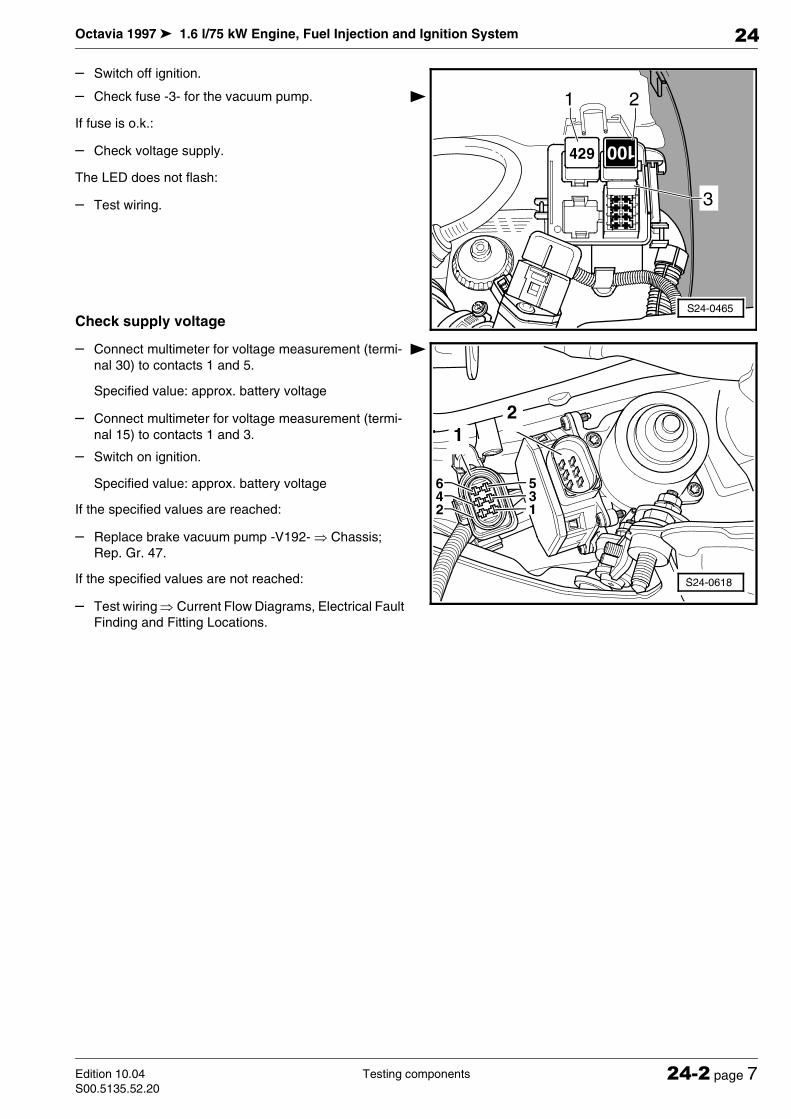
Octavia 1997 1.6 l/75 kW Engine, Fuel Injection and Ignition System
Testing componentsEdition 10.04
S00.5135.52.2024-2 page 7
24
– Switch off ignition.
– Check fuse -3- for the vacuum pump.
If fuse is o.k.:
– Check voltage supply.
The LED does not flash:
– Test wiring.
Check supply voltage
– Connect multimeter for voltage measurement (termi-
nal 30) to contacts 1 and 5.
Specified value: approx. battery voltage
– Connect multimeter for voltage measurement (termi-
nal 15) to contacts 1 and 3.
– Switch on ignition.
Specified value: approx. battery voltage
If the specified values are reached:
– Replace brake vacuum pump -V192- µ Chassis;
Rep. Gr. 47.
If the specified values are not reached:
– Test wiring µ Current Flow Diagrams, Electrical Fault
Finding and Fitting Locations.
S24-0465
2
3
1

Octavia 1997 1.6 l/75 kW Engine, Fuel Injection and Ignition System
Testing components Edition 10.04
S00.5135.52.2024-2 page 8
24
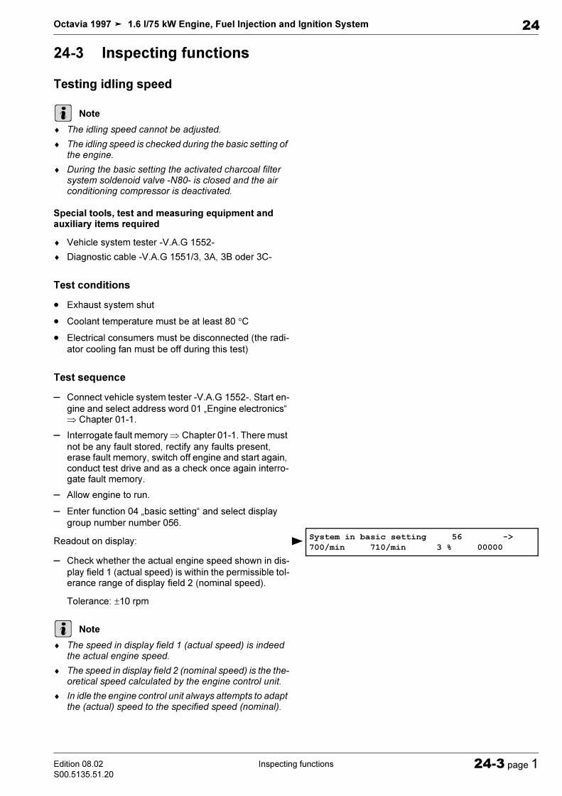
!"#$ %&' %
% ()% * ( ()( ! " # ! $% % & '
' ( ' #' # )
# *
')+ ' , !
- . / '
+ '0 # %% %- % ,1
+ - + 2.#/
##34 5+ '1- -
)*-# ) *0 5
!
" !
# $ ! !
+
+

$ !
$ % !
& '
,5+ 64 5, 5+ '&, %,,( -&,(& ,& (%(&( ,& -% (-,%. 1 '
2 0 ,, '2 0, ,,
7 ' 8 ,, '23 '1 54
,# 1% ' 6 ,, (
'23
', & ,(0 # #- 9% -(
' 0 #'% ()% * ( ()( ! 3 :,- )
! ;* ! " # ! $% % & ' :) ! < * #) ! ;2
! ;2 ' *
')+ #
- -,#1 ,,,73-% 1 -5
!""

+ ' , ! - . / '
+ .,# 1/ #;
+ 4 5+ 6 - +
% 1 ,2
2# . / . /# # 95+ ,
+ , 1+ ,#1
, 1 -5
+ ", ,#1
, -,#1 ,,,
+ '1,
+ ' , ! ; , ! 3) &*
+ ' , ,#1 , ,) *
+ = ,, $&+ > ! ;,&,
( =6)#*0, , 5+ 4 '2 5+ '1 , 1
,+ 4 ,1 ##
'2 5+ 4
#$ %$& !'(%)*+(+,!
+
$%
1
!3 !;

2

!"#" $ %& !!!"#!$!!"!"% &'" ()*+, &-" !"."/"0.
' %(&%#)*# %& (& + &&( &,( - & &,& 1"123 " 0"123 )4 24 / 5" "123 -)" 6!7"123 *"8 27"123 -' 2""123 -' 5 "8
' 5+!!.9 5" $!'.9 5!!5 !
',5+!"3-"!#!!:;!#!+<4!!444' 5"(=#!%> > 0("!"3-"
> ?!! '!
! ;" 3-"!"
S97-0319
1
2
3
4
6
7
10 14
15
18
19
22
23
5
8
9
12
13
16
17
20
21
11
24
25
26
27
28
29
30
31
32
33
34
35
36
37
38
39
40
41
42
43
44
'
1
.
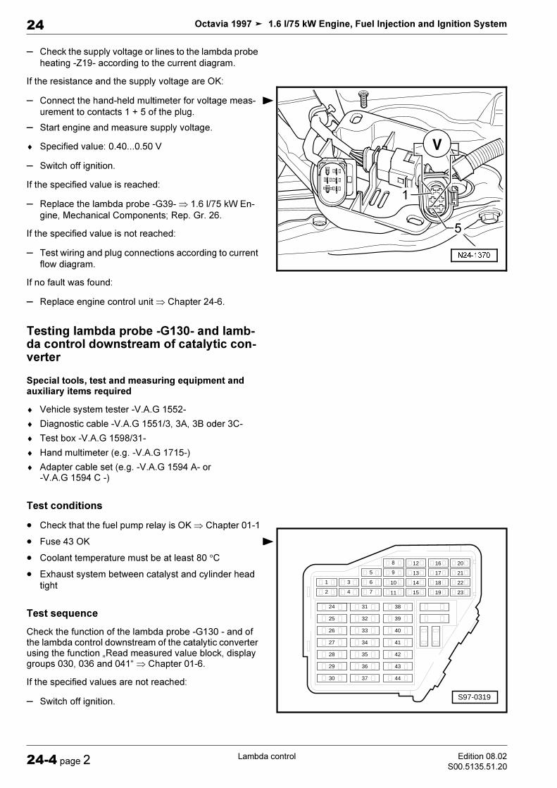
> 5+!#"@-"!
=!#.9%> 5"!#"!A!
> !!# #!%' 1> =#!%> ;"3-" ()*+, "4B5C; 3 (
=#!%> !!
=! !%> ;! 5'"(
' %(&%#)*/# %#& 0& + #&&( &,( - & &,& 1"123 " 0"123 )4 24 / 5" "123 -)" 6!7"123 *"8 27"123 -' 2""123 -' 5 "8
' 5+!!.9 5" $!'.9 5!!5 !
',5+!"3 " #!!:;!#!+4!4('< 5"(=#!%>
1
S97-0319
1
2
3
4
6
7
10 14
15
18
19
22
23
5
8
9
12
13
16
17
20
21
11
24
25
26
27
28
29
30
31
32
33
34
35
36
37
38
39
40
41
42
43
44

> 0'"!"3"
> ?!! !
! =!4"3"> 5+!# #"@-"!
=!#.9%> 5"!#"!A'!""
> !!# #!%' 1> =#!%> ; "#"3" ()*+, 4B"5C; 3 (
=#!%> !!
=! !%> ;! 5'"(
'++ %(&%(& + &&#)*#( &,( - & &,& 1"123 " 0"123 )4 24 / 5"
' $!!.94 5" $!'.9 5!!5 !
1
.
'
1
6
S97-0319
1
2
3
4
6
7
10 14
15
18
19
22
23
5
8
9
12
13
16
17
20
21
11
24
25
26
27
28
29
30
31
32
33
34
35
36
37
38
39
40
41
42
43
44
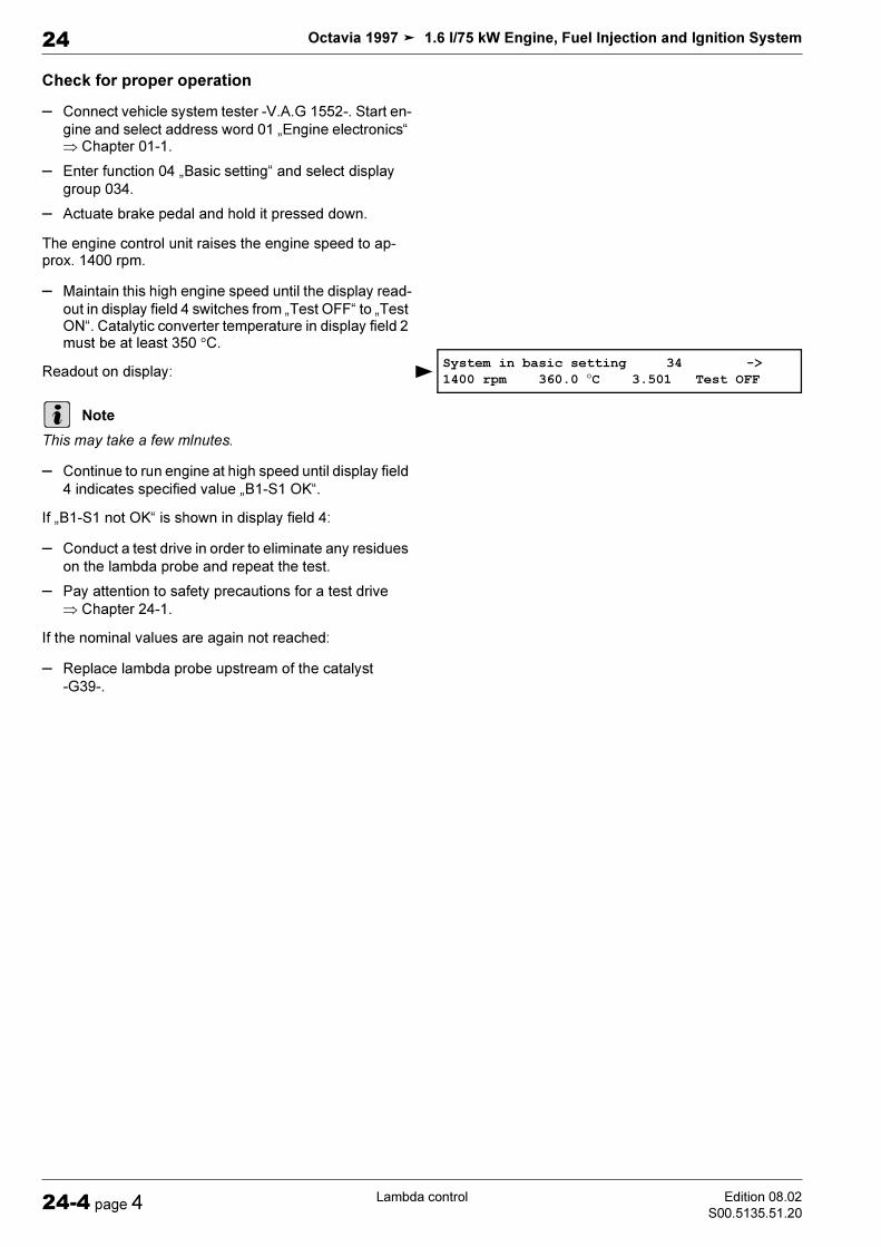
'
12+&(&(&(&> 5#"123 "" : < 5"
> !':/<!'
> 2!+ !"'> B!"!' :.$$<:.D<5#!!5
;!%
"#> 5!!!'#!:/".9<
=:/".9< '%> 5!#!
> &!# 5'"
=#!%> ;!"3-"
.
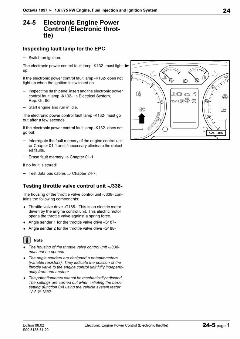
!"# $%&$'$ ( $)$# *
+, +,$)%' !"#"! $ % !"#"$ $$ %$$$
!"#" &$!'( ) *
!"#"! $ $$% !"#"$ % !!&
"$$&!" $
$ !!& "% $$+ $, $,$ -".
-)$ $ #.//0# $// "0""$ !$+ ///")1"$$!
/,& $!$//$$
2$///")." 2$///")"
! "#$ %&&'
6
1
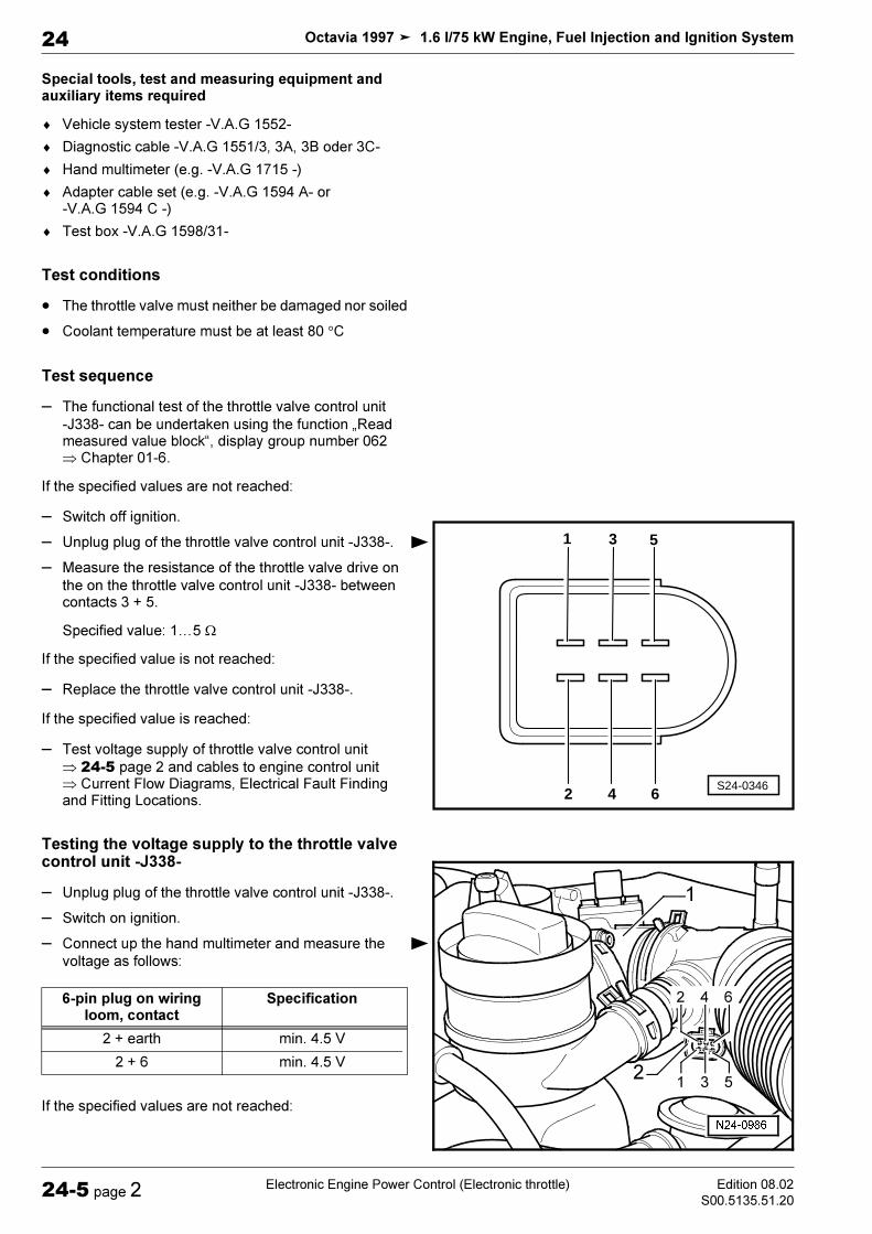
+ $2+ 3 $ $2$ 3$&$!$"32) " 4$,"32) 56 26 7 " 8! !"32) . " 2,$"32) *- 2"
"32) *- " $,9"32) *5"
- //! $,!$ ! ! $,$
-2 $//
"0", : $ ;(!$ / ,:<6$& !,1 "1
%$/ $+ = // "0" >$ $$///
// "0", $?/ +@
%$/ $+ (// "0"%$/ $+ $/$ &//
,$ A 4!$6A AAB$
-) ++ ))$ $ #.//0# = // "0" ! !!$
/$ $+
%$/ $+
2S24-0346
4 6
3 51
1
- 1#++ &$
+,
? !- 3?1 !- 3

:,$! // "0" A 4"!$6A AAB$
% $ + ( -"1
-4 $$+ +#$ $$$").*"")"$$/ !&"& $$$7$$ $+ $2+ 3 $ $2$ 3$&$!$"32) " 4$,"32) 56 26 7 " 8! !"32) ." 2,$"32) *- 2"
"32) *- " $,9"32) *5"
'),$+$+$+$ $$
$, : $ ;(!$ / ,:<6$& !,1 "1
%$/ $+ $/$ &
$$
-)+&$++ ,)4 $$+ +$ (!/ $$
/C$$ 7& :'( ) . 4$$
$$ ! !!$
/$ $+
%$/ $+
#++ &$
+,
? !- 3? !- 3
? !- 3? !- 3

-
$ ! "$$$ A 4"!$6A AAB$
%,$ , &+ ( -"1

!"# $ %$ ! " #$% & ' (
&% $ % $'% ( $ $'$ ) ()* ( +!()* ,(()* ,(()* ,-(()* ,&(
)$$. &% ()* (' '/ ' 0 &(
#% ()* ( ( 1. #$ ' . / 0 '
& . '. 2 %' ' $% ! - 34$52 *
. 6' % 7( ('
. 2$
"%
*
A23-0026
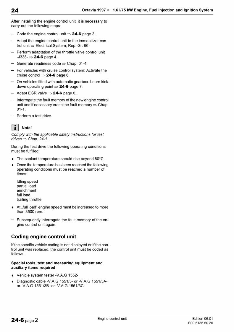
'1. & . !8( 52 * 9
. : %%(;<( =
. * &(=
. 3%' 1%
. >% ' !71$$( ' ?
. *2%%
. " ' &(
. : %
+ %' ! 1 # ! <& > ! ' ! ! 1"
/ 0 !
. !@ (
+$ "% (' ! '% $'% ( $ $'$ ) ()* ( +!()* ,(()* ,(()* ,-(()* ,&(
*
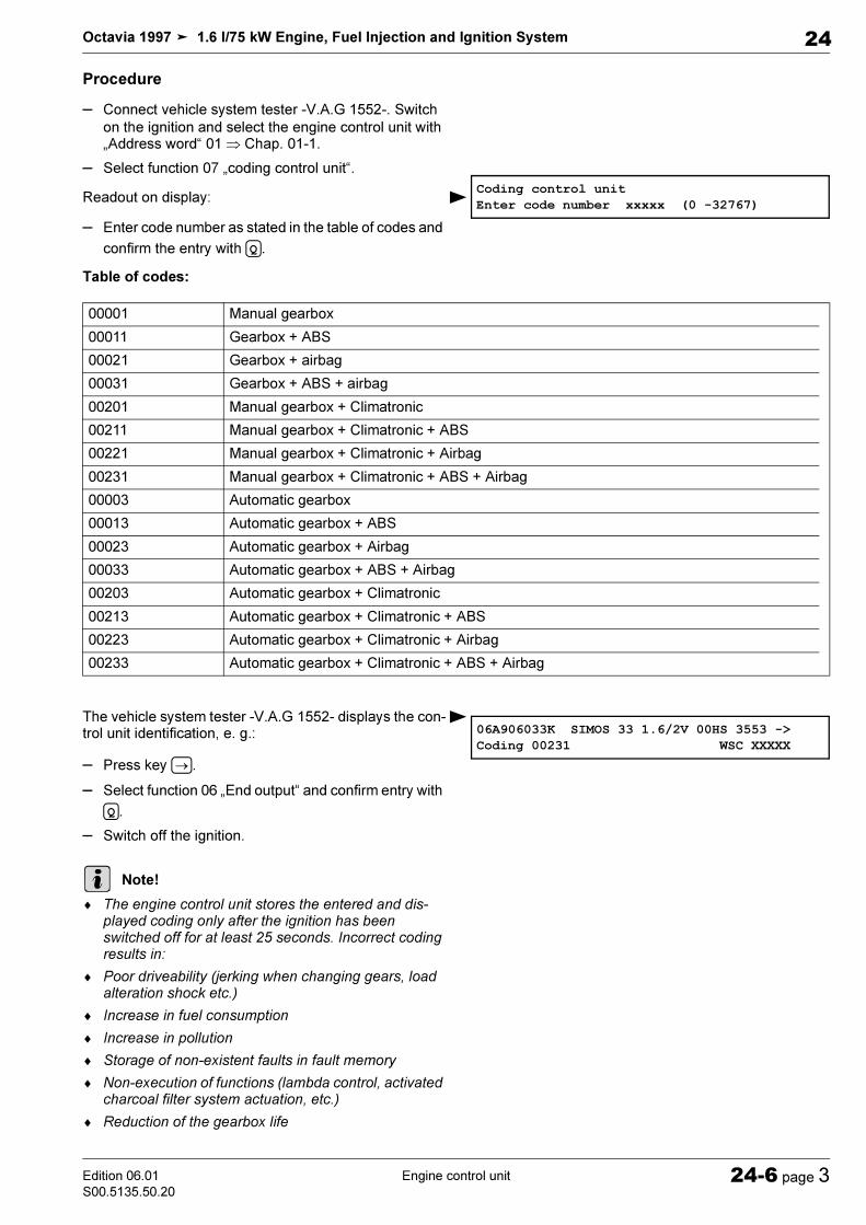
)$$. &% ()* (' '/ ' 0 &(
. ?/ 02 1. ! ! '
,- ./
#% ()* ( ( 1. :$ . / 0 '
. '
!"#$
%&' (
# # )* +*&
( ,*
!"#$ $"%&$ '''''())*
A!7 *!7B- *!7B! *!7B-B! A!7B& A!7B& B- A!7B& B! A!7B& B-B! !7 !7B- !7B! !7B-B! !7B& !7B& B- !7B& B! !7B& B-B!
*
=
0%1"02$ 11$ $ #3445## %(%%' # #$' %%%'%% % ' %%(;<( % ( %( #C D !!C=D '
'' '% ( / 0C ''%' 'D( %% ' %%%
!% $'% ( $ $'$ ) ()* ( +!()* ,(()* ,(()* ,-(()* ,&(
, E
&( '( ' !'
#%% ! & !%&!!'& "$ !'& -%) 3%' 1&$'% &("/*0 ( !%
*

)$$. &% ()* (' '/ ' 0 &(
. =/-0 !
%%' " %% ' (! %%(;<(#%( !' !!@%% %%("% %%' E' %%'% %( CD#%%!@ !%%1%! %%(;<( ("'%%( % ! '( #(' ! 2 1. &$ %%%(;<( =
2 1 % =1+:+:$
!-./%0-.0" ! ! ! '1 #%%! C D #!%' # (
4%%C$' D
! /($'! 04' C' D
. !!
+,$%&-,,$ ./ ./01 "
+,$%&-,,$ ./ .01 2
*
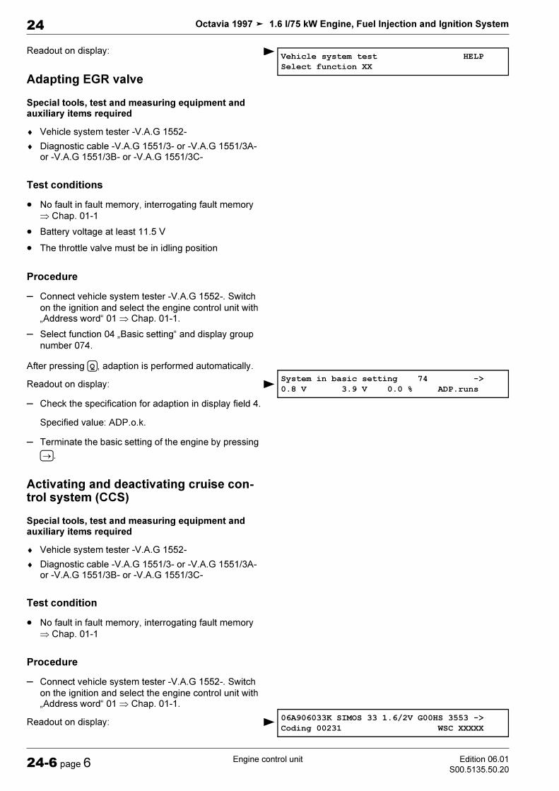
2 1
0%6& % $'% ( $ $'$ ) ()* ( +!()* ,(()* ,(()* ,-(()* ,&(
, E
&( -%) #%% !
)$$. &% ()* (' '/ ' 0 &(
. =/-0 !?=
2 1. &$ = %1+:$
. # !!
0$#$ 7++8% $'% ( $ $'$ ) ()* ( +!()* ,(()* ,(()* ,-(()* ,&(
, E
&(
)$$. &% ()* (' '/ ' 0 &(
2 1
$3!$,+,$%$,#41$!$5"
+,$%&-,,$)6 / .01 ",
7
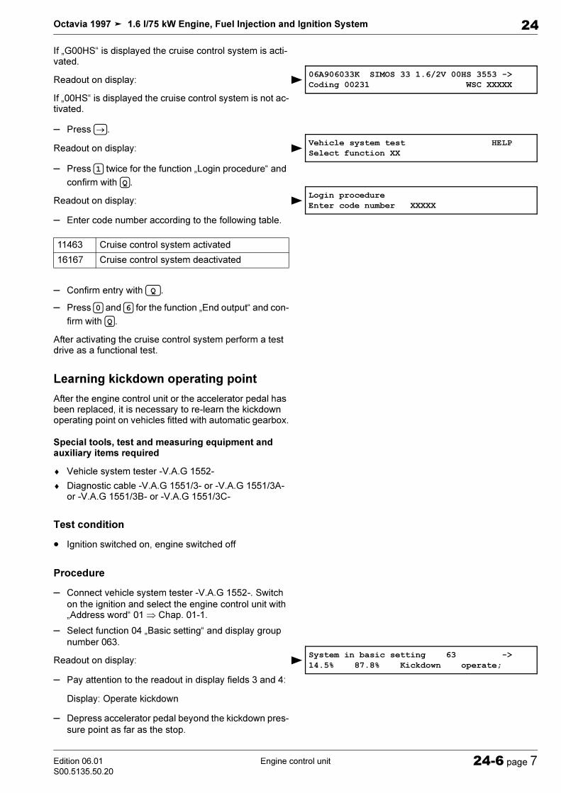
?
"/*F0 (% 2 1"/F0 (% . : 2 1. : '/ 0 '
2 1. ! '!
. & '
. : / 0 ( '
% %
9$:%$% ! ($$ '% ' !7% $'% ( $ $'$ ) ()* ( +!()* ,(()* ,(()* ,-(()* ,&(
, "' '
)$$. &% ()* (' '/ ' 0 &(
. =/-0 !
2 1. : =1+1>$$ '
. + ! $$ '(
$3!$,+,$%$,#41$!$5"
48 $" $#$ $"%&$
= & % ? & %
+,$%&-,,$6 ./) /.298$ -$:
<
. F (
. : =1 %1G$ '+: %1G$ '+:$
"' =1/G$ '22>20. !! . / 0 '
. # &=(
. " ! &(

!"# $% & $ '& (()&&#&'&(& #*#) &+) % & &+& ! "# ! $% % & ' ( ) ! *+ #) ! ,-
! ,- ' + # ! ,$
$ .. #
/0 #1.. #. .
' 2# )#23
'+
$+4. . !567 % 189:)1+. ; '2 !
1 < = '
; .< 2#>= # *
; ?6; @. -1
A B; 1 ; 1 #1 2; .
A5 B7. -B6; 8 ; .5<=. 1
; 1..

; C- )+. @)+
; ' . 2 1 #)2+3) +. .
; 1.26
; 1..7..2 6; #.
' D1" % DDD4
$() # ! ,. . #. E .) &+) % & &+& ( ) ! *+ ") ! * &+ #) ! ,-
! ,- ' + # ! ,$ ' .1
$ / . /0%
F? ! ,
$+; '# ! ,$ 1
. ' -
6
6

; ?2. .1 .
; '#1#)2+#,)+.# ! ,$
; 1; .. 1#.)2 .+7..6; 1
! .1
,((-.) &+) % & &+& ( ) ! *+ #) ! ,-
! ,- ' + # ! ,$
$ .#1#
'. /0
$+; 1..; C> ; '# ! ,$
' -1 .
;
; : #1#>,3-.265A*
7. 1. 6; ? ' -57. 1. 6; .&C#
&C ' D1" % DDD4

-

Octavia 1997 1.6 l/75 kW Engine, Fuel Injection and Ignition System
Ignition SystemEdition 10.04
S00.5135.52.2028-1 page 1
28
28-1 Ignition System
General notes on the ignition system
♦ The engine control unit is equipped with a self-diagno-sis system.
♦ A minimum voltage of 11.5 V is required for perfect functioning of the electrical components.
♦ Certain inspections may cause the control unit to de-tect and store a fault. It is therefore necessary to inter-rogate the fault memory after having completed all inspections and repairs, and if necessary delete.
♦ If after fault finding, repair or inspection of compo-nents the engine starts briefly and then stops, it is pos-sible that the immobiliser blocks the 4AV control unit. In this case the fault memory must be interrogated and if necessary the control unit must be adapted.
Safety measures
Observe the following points to prevent injury to persons and/or damage to the injection and preheating system:
♦ Do not touch or remove ignition leads with the engine running or at start speed.
♦ Disconnect and connect wires of the injection and pre-heating system and measuring device wires when the ignition is switched off.
♦ To operate the engine at start speed without it starting (e.g. for a testing compression pressure), unplug con-nectors from the ignition unit and connectors from the injectors. After performing the work interrogate fault memory and erase.
♦ Do not carry out engine wash unless the ignition is switched off.
♦ Switch off the ignition before disconnecting and con-necting the battery, as this may damage the 4AV con-trol unit.
♦ If the engine must be operated at start speed without the engine starting:
– Unplug 4-pin connector -1- from ignition transformer
-2-.
28 – Ignition System
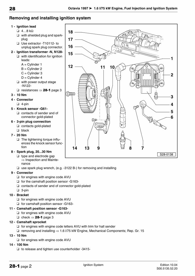
Octavia 1997 1.6 l/75 kW Engine, Fuel Injection and Ignition System
Ignition System Edition 10.04
S00.5135.52.2028-1 page 2
28
Removing and installing ignition system
1 - Ignition lead
4…8 kΩ
with shielded plug and spark-plug
Use extractor -T10112- to unplug spark plug connector.
2 - Ignition transformer -N, N128-
with identification for ignition leads:
A = Cylinder 1
B = Cylinder 2
C = Cylinder 3
D = Cylinder 4
with power output stage -N122-
resistances µ 28-1 page 3
3 - 10 Nm
4 - Connector
4-pin
5 - Knock sensor -G61-
contacts of sender and of connector gold-plated
6 - 3-pin plug connection
contacts gold-plated
black
7 - 20 Nm
The tightening torque influ-ences the knock sensor func-tion
8 - Spark plug, 20...30 Nm
type and electrode gap µ Inspection and Mainte-nance
use spark plug wrench, (e.g. -3122 B-) for removing and installing
9 - Connector
for engines with engine code AVU
for the camshaft position sensor -G163-
contacts of sender and of connector gold-plated
3-pin
10 - Bracket
for engines with engine code AVU
for camshaft position sensor -G163-
11 - Camshaft position sensor -G163-
for engines with engine code AVU
check µ 28-1 page 3
12 - Camshaft sprocket
for engines with engine code letters AVU with trim for hall sender
removing and installing µ 1.6 l/75 kW Engine, Mechanical Components; Rep. Gr. 15
13 - 10 Nm
for engines with engine code AVU
14 - 100 Nm
to release and tighten use counterholder -3415-
B
AC
D

Octavia 1997 1.6 l/75 kW Engine, Fuel Injection and Ignition System
Ignition SystemEdition 10.04
S00.5135.52.2028-1 page 3
28
15 - 10 Nm
for engines with engine code BFQ
16 - Camshaft position sensor -G163-
for engines with engine code BFQ
check µ 28-1 page 3
17 - Gasket ring
for engines with engine code BFQ
replace if damaged
before fitting moisten with clean engine oil
18 - Rotor
for engines with engine code BFQ
on the camshaft
Resistances of ignition coils
What is tested is the resistance between contacts 2 + 3 and 1 + 4.
Specified value: 4.0...6.0 kΩ (at approx. 20 °C)
Inspecting the camshaft position sensor -G163-
The camshaft position sensor -G163- indicates the igni-tion position for cylinder 1.
If it fails the knock control is deactivated and the ignition angle is slightly reduced as a cylinder assignment is no longer possible.
Without sensor signal the engine runs on and can be started again:
♦ In the event of a fault detection the engine control unit generates an ignition spark per cylinder for each crankshaft rotation.
♦ There is no noticeable effect on the injection if there is a displacement of an engine revolution. Instead of oc-curring with the injection valve open the injection oc-curs "pre-engaged" (before the closed injection valve). This only has a very slight influence on the quality of the mixture formation.
♦ The camshaft position sensor -G163- is identical to the Hall sender -G40-.
♦ The correct setting of the timing can be checked in measured value block 012 µ Chapter 01-5.
Special tools, test and measuring equipment and auxiliary items required
♦ Hand multimeter (e.g. -V.A.G 1715-)
♦ Adapter cable set (e.g. -V.A.G 1594 A, B oder C-)
♦ Test box -V.A.G 1598/31-
Note

Octavia 1997 1.6 l/75 kW Engine, Fuel Injection and Ignition System
Ignition System Edition 10.04
S00.5135.52.2028-1 page 4
28
Test sequence
– Unplug the plug on the camshaft position sensor
-G163- -arrow-.
For engines with engine code BFQ
For engines with engine code AVU
Continued for all engines
– Switch on ignition.
– Connect up hand multimeter and measure the voltage
as follows:
For engines with engine code BFQ
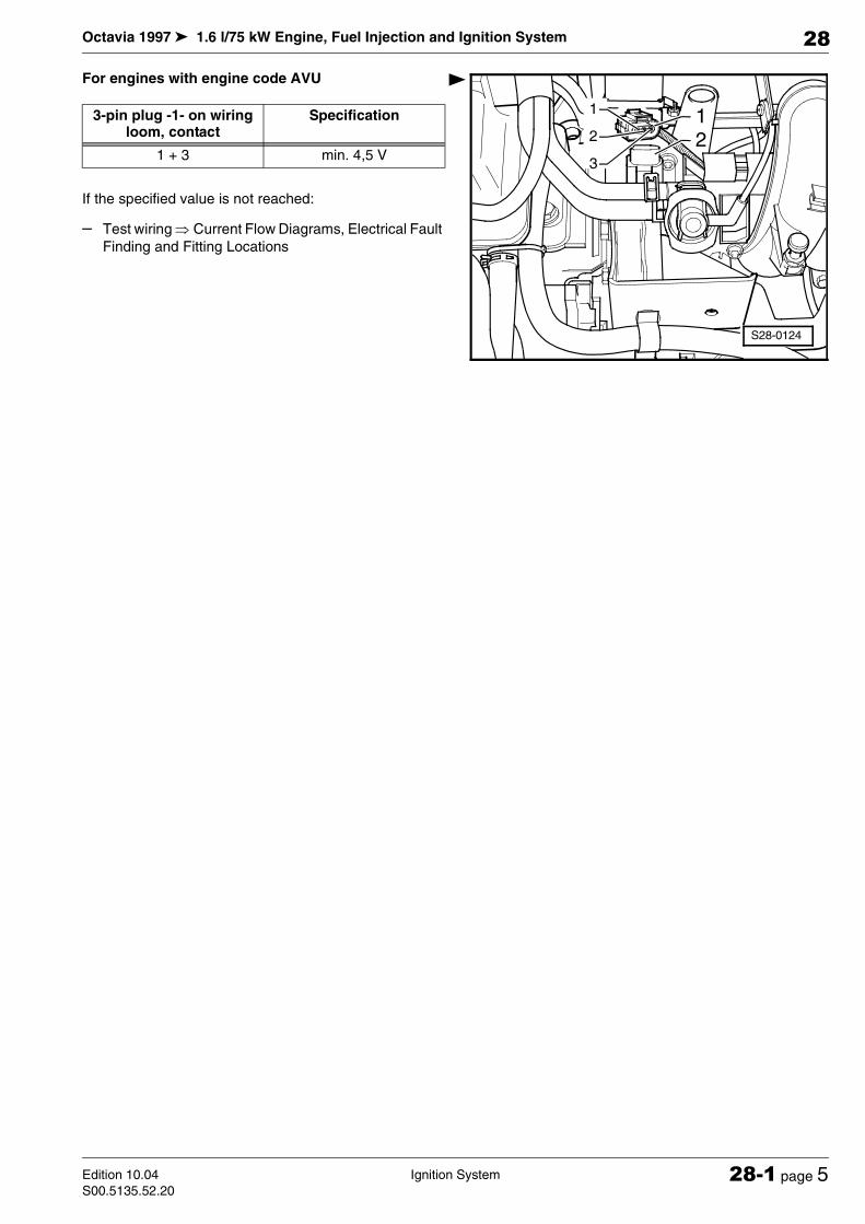
Octavia 1997 1.6 l/75 kW Engine, Fuel Injection and Ignition System
Ignition SystemEdition 10.04
S00.5135.52.2028-1 page 5
28
For engines with engine code AVU
If the specified value is not reached:
– Test wiring µ Current Flow Diagrams, Electrical Fault
Finding and Fitting Locations
S28-0124
12
1
3
2
3-pin plug -1- on wiring loom, contact
Specification
1 + 3 min. 4,5 V

Octavia 1997 1.6 l/75 kW Engine, Fuel Injection and Ignition System
Ignition System Edition 10.04
S00.5135.52.2028-1 page 6
28


