
1452 Tech spec
158
TENDER SPECIFICATION BHEL: PSSR: SCT: 1452 FOR Handling at Site Store / Storage Yard, Transportation to Site of Work, Erection, Testing and Commissioning of 3 Nos. Frame 9E Gas Turbine, Generator and its Auxiliaries, 2 Nos. of 30 MW Steam Turbine, Generators and their Auxiliaries, including integral piping and insulation, and Balance of Plant Equipment, including Supply and Application of Final Painting. at IOCL- PARADIP REFINARY PROJECT 366MW CO-GENERATION CPP PACKAGE Paradip, Orissa VOLUME –I BOOK - I TECHNOCOMMERCIAL BID (Book I & II) Book-I consists of o Notice Inviting Tender, o Volume-IA : Technical Conditions of Contract Book-II consists of o Volume-IB : Special conditions of Contract, o Volume-IC : General conditions of Contract o Volume-ID : Forms & Procedures BHARAT HEAVY ELECTRICALS LIMITED (A Government of India Undertaking) Power Sector – Southern Region 690, Anna Salai, Nandanam, Chennai – 600 035.
Transcript of 1452 Tech spec

TENDER SPECIFICATION BHEL: PSSR: SCT: 1452
FOR
Handling at Site Store / Storage Yard, Transportation to Site of Work, Erection, Testing and Commissioning of 3 Nos. Frame 9E Gas Turbine, Generator and its Auxiliaries, 2 Nos. of 30 MW Steam Turbine, Generators and their Auxiliaries, including integral piping and insulation, and Balance of Plant Equipment, including Supply and Application of Final Painting.
at
IOCL- PARADIP REFINARY PROJECT
366MW CO-GENERATION CPP PACKAGE
Paradip, Orissa
VOLUME –I BOOK - I
TECHNOCOMMERCIAL BID (Book I & II)
Book-I consists of
o Notice Inviting Tender, o Volume-IA : Technical Conditions of Contract
Book-II consists of
o Volume-IB : Special conditions of Contract, o Volume-IC : General conditions of Contract o Volume-ID : Forms & Procedures
BHARAT HEAVY ELECTRICALS LIMITED (A Government of India Undertaking)
Power Sector – Southern Region 690, Anna Salai, Nandanam, Chennai – 600 035.

BHARAT HEAVY ELECTRICALS LIMITED (A Government of India Undertaking)
Power Sector, Southern Region 690, Anna Salai, Nandanam, Chennai – 35
Tender Specification No. BHEL: PSSR: SCT: 1452
for
Handling at Site Store / Storage Yard, Transportation to Site of Work, Erection, Testing and Commissioning of 3 Nos. Frame 9E Gas Turbine, Generator and its Auxiliaries, 2 Nos. of 30 MW Steam Turbine, Generators and their Auxiliaries, including integral piping and insulation, and Balance of Plant Equipment, including Supply and Application of Final Painting at IOCL- Paradip Refinery Project, 366MW Co-generation CPP Package, Paradip, Orissa
One set of Tender documents consisting of
1) TECHNOCOMMERCIAL BID - 2 copies 2) PRICE BID - 2 copies
Book Sl no ………. Issued to M/s
Refer NIT for Last date of submission Please note this tender document is not transferable
For and on behalf of BHARAT HEAVY ELECTRICALS LIMITED
ADDL GENERAL MANAGER / CONTRACTS
Place: Chennai -35 Date:

NOTICE INVITING TENDER
Rev 00 6th July 2010
Bharat Heavy Electricals Limited

Ref: BHEL PSSR SCT 1452 Date: Mar 17, 2011
NOTICE INVITING TENDER (NIT)
NOTE: BIDDER MAY DOWNLOAD FROM WEB SITES OR
PURCHASE TENDERS FROM THIS OFFICE ALSO ================================================================================
To
Dear Sir / Madam
Sub : NOTICE INVITING TENDER
Sealed offers in two part bid system are invited for the subject job by the undersigned on the behalf of BHARAT HEAVY ELECTRICALS LIMITED as per the tender document. Following points relevant to the tender may please be noted and complied with.
1.0 Salient Features of NIT Sl. No
ISSUE DESCRIPTION
i TENDER NUMBER
BHEL PSSR SCT 1452
ii Broad Scope of job
Handling at Site Store / Storage Yard, Transportation to Site of Work, Erection, Testing and Commissioning of 3 Nos. Frame 9E Gas Turbine, Generator and its Auxiliaries, 2 Nos. of 30 MW Steam Turbine, Generators and their Auxiliaries, including integral piping and insulation, and Balance of Plant Equipment, including Supply and Application of Final Painting at IOCL- Paradip Refinery Project, 366MW Co-generation CPP Package, Paradip, Orissa
iii DETAILS OF TENDER DOCUMENT
a Volume-IA Technical Conditions of Contract (TCC) consisting of Scope of work, Technical Specification, Drawings, Procedures, Bill of Quantities, Terms of payment, etc
Applicable
b Volume-IB Special Conditions of Contract (SCC) Applicable
c Volume-IC General Conditions of Contract (GCC) Applicable
d Volume-ID Forms and Procedures Applicable
e Volume-II Price Schedule (Absolute value). Applicable
iv Issue of Tender Documents
1. Sale from BHEL PSSR Regional office at :Chennai
Start : Mar 21, 2011 Closes: Apr 11, 2011 , Time :15.00 Hrs
Applicable

2. From BHEL website (www.bhel.com) Tender documents can however be downloaded
from website till due date of submission
v DUE DATE & TIME OF OFFER SUBMISSION
Date : Apr 12, 2011, Time :15.00Hrs Place : BHEL PSSR :Chennai Tenders can be submitted through representative / in person at SCT Dept, BHEL PSSR, Chennai.
Applicable
vi OPENING OF TENDER
Date : Apr 12, 2011, Time :15.30Hrs Notes: (1) In case the due date of opening of tender becomes
a non-working day, tenders shall be opened on next working day at the same time.
(2) Bidder may depute representative to witness the opening of tender
Applicable
vii EMD AMOUNT
Rs 2,00,000/- (Rupees Two Lakhs Only) Applicable
viii COST OF TENDER
Rs 2000/-. Applicable
ix LAST DATE FOR SEEKING CLARIFICATION
At least 7 days before the due date of offer submission or two days before the scheduled date of pre-bid meeting whichever is earlier Along with soft version also, addressing to undersigned & to others as per contact address given below
Applicable
x SCHEDULE OF Pre Bid Discussion (PBD)
Date: Mar 31, 2011. Time 10.00AM at BHEL:PSSR:Chennai-35
Applicable
xi INTEGRITY PACT & DETAILS OF INDEPENDENT EXTERNAL MONITOR (IEM)
Bidders shall enter into an Integrity Pact (IP) with BHEL as per format given at Volume 1D Formats of this tender. The bidders are required to return this Integrity Pact (IP) along with Techno Commercial Bid duly signed and stamped by the authorized signatory who signs the bid. It may be noted that only those bidders who have entered into such an IP with BHEL would be competent to participate against this tender .i.e. entering into this pact is a preliminary qualifications for the bidders. The Independent External Monitor against this NIT shall be Shri ...
Not Applicable

xii Latest updates
Latest updates on the important dates, Amendments, Correspondences, Corrigenda, Clarifications, Changes, Errata, Modifications, Revisions, etc to Tender Specifications will be hosted in BHEL webpage (www.bhel.com Tender Notifications View Corrigendums) and not in the newspapers. Bidders to keep themselves updated with all such information
2.0 The offer shall be submitted as per the instructions of tender document and as detailed in this NIT. Bidders to note specifically that all pages of tender document, including these NIT pages of this particular tender together with subsequent correspondences shall be submitted by them, duly signed & stamped on each page, as part of offer. Rates / Price including discounts / rebates, if any, mentioned anywhere/in any form in the techno-commercial offer other than the Price Bid, shall not be entertained.
3.0 Unless specifically stated otherwise, bidder shall remit cost of tender and courier charges if applicable, in the form of Demand Draft drawn in favour of Bharat Heavy Electricals Ltd, payable at Power Sector Regional HQ at Chennai issuing the Tender, along with techno-commercial offer. Bidder may also choose to deposit the Tender document cost by cash at the Cash Office as stated above against sl no iv of 1, on any working day; and in such case copy of Cash receipt is to be enclosed with the Techno Commercial offer. Sale of tender Documents shall not take place on National Holidays, holidays declared by Central or State Governments and BHEL PS HQ at Chennai, Sundays and second/ last Saturdays
4.0 Unless specifically stated otherwise, bidder shall deposit EMD through Demand Draft/Pay Order in favour of Bharat Heavy Electricals Ltd, payable at Chennai. For other details and for ‗One Time EMD‘ please refer General Conditions of Contract.
5.0 Procedure for Submission of Tenders: The Tenderers must submit their Tenders to Officer inviting Tender, as detailed below:
PART-I consisting of ‗PART-I A (Techno Commercial Bid)‘ & ‗PART-I B (EMD/COST of TENDER)‘ in two separate sealed and superscribed envelopes (ENVELOPE-I & ENVELOPE-II)
PART-II(Price Bid) – in sealed and superscribed envelope (ENVELOPE-III)
One set of each document shall be retained by the bidder for their reference.

6.0 The contents for ENVELOPES and the superscription for each sealed cover / Envelope are as given below. (All pages to be signed and stamped)
Sl no
Description Remarks
Part-I A
ENVELOPE – I superscribed as : PART-I (TECHNO COMMERCIAL BID) TENDER NO : NAME OF WORK : PROJECT: DUE DATE OF SUBMISSION:
CONTAINING THE FOLLOWING:-
i. Covering letter/Offer forwarding letter of Tenderer.
ii. Duly filled-in `No Deviation Certificate' as per prescribed format to be placed after document under sl no (i) above. Note: a. In case of any deviation, the same should be submitted separately
for technical & commercial parts, indicating respective clauses of tender against which deviation is taken by bidder. The list of such deviation shall be placed after document under sl no (i) above. It shall be specifically noted that deviation recorded elsewhere shall not be entertained.
b. BHEL reserves the right to accept / reject the deviations without assigning any reasons, and BHEL decision is final and binding.
c. In case of acceptance of the deviations, appropriate loading shall be done by BHEL
(ii) In case of unacceptable deviations, BHEL reserves the right to reject the tender.
iii. Supporting documents / annexure / schedules / drawing etc as required in line with Pre-Qualification criteria.
It shall be specifically noted that all documents as per above shall be indexed properly and credential certificates issued by clients shall distinctly bear the name of organization, contact ph no, FAX no, etc.
iv. All Amendments / Correspondences / Corrigenda / Clarifications / Changes / Errata etc pertinent to this NIT.
v. Integrity Pact Agreement (Duly signed by the authorized signatory) If appli cable
vi. Duly filled-in annexures, formats etc as required under this Tender Specification/NIT
vii. Notice inviting Tender (NIT)

viii. Volume – I A : Technical Conditions of Contract (TCC) consisting of Scope of work, Technical Specification, Drawings, Procedures, Bill of Quantities, Terms of payment, etc
ix. Volume – I B : Special Conditions of Contract (SCC)
x. Volume – I C : General Conditions of Contract (GCC)
xi. Volume – I D : Forms & Procedures
xii. Volume – II (UNPRICED – without disclosing rates / price, but mentioning only ‗QUOTED‘ or ‗UNQUOTED‘ against each item
xiii. Any other details preferred by bidder with proper indexing.
PART-I B
ENVELOPE – II superscribed as: PART-I (EMD/COST of TENDER) TENDER NO : NAME OF WORK : PROJECT: DUE DATE OF SUBMISSION: CONTAINING THE FOLLOWING:-
i. 1. Earnest Money Deposit (EMD) in the form as indicated in this Tender OR
Documentary evidence for ‗One Time EMD‘ with BHEL PSSR Chennai
2. Cost of Tender (Demand Draft or copy of Cash Receipt as the case may be)
PART-II
PRICE BID consisting of the following shall be enclosed
ENVELOPE-III superscribed as: PART-II (PRICE BID) TENDER NO : NAME OF WORK : PROJECT: DUE DATE OF SUBMISSION:
CONTAINING THE FOLLOWING
i Covering letter/Offer forwarding letter of Tenderer enclosed in Part-I
ii Volume II – PRICE BID ( Duly Filled in Schedule of Rates – rate/price to be entered in words as well as figures)

OUTER COVER
ENVELOPE-IV (MAIN ENVELOPE / OUTER ENVELOPE) superscribed as: TECHNO-COMMERCIAL BID, PRICE BID & EMD TENDER NO: NAME OF WORK: PROJECT: DUE DATE OF SUBMISSION:
CONTAINING THE FOLLOWING:
i o Envelopes I o Envelopes II o Envelopes III
SPECIAL NOTE: All documents/ annexures submitted with the offer shall be properly annexed and placed in respective places of the offer as per enclosure list mentioned in the covering letter. BHEL shall not be responsible for any missing documents.
7.0 No Deviation with respect to tender clauses and no additional clauses/ suggestions/ in Techno-commercial bid/ Price bid shall normally be considered by BHEL. Bidders are requested to positively comply with the same.
8.0 BHEL reserves the right to accept or reject any or all Offers without assigning any reasons thereof. BHEL also reserves the right to cancel the Tender wholly or partly without assigning any reason thereof. Also BHEL shall not entertain any correspondence from bidders in this matter (except for the refund of EMD).
9.0 Assessment of Capacity of Bidders: (Shall be applicable for all Bid Evaluation from 1st April 2011) Bidders capacity for executing the job under tender shall be assessed as per the following:
I. Assigning Weightages (A) for Similar Jobs Under-Execution: Weightages shall be worked out and assigned based on the average number of Similar Works under execution including works yet to be commenced by the agency, in the following manner:
i). Number of Similar Jobs a) No. of jobs in BHEL, PSER : Say ‗J‘ b) No. of jobs in BHEL, PSSR : Say ‗K‘ c) No. of jobs in BHEL, PSWR : Say ‗L‘ d) No. of jobs in BHEL, PSNR : Say ‗M‘ e) No. of jobs with other customers* : Say ‗N‘ (*: Other than BHEL PSER, PSSR, PSWR & PSNR) f) Average No. of Jobs is ‗P‘= (J+K+L+M+N) divided by 5

ii) Weightage ―A‖ assigned to bidders based on Average Number of jobs ―P‖; a) If ‗P‘ = 0-1, ―A‖ will be equal to ‗3‘ b) If ‗P‘ = 2-3, ―A‖ will be equal to ‗2‘ c) If ‗P‘ = 4-5, ―A‖ will be equal to ‗1‘ d) If ‗P‘ is Above 5, ―A‖ will be equal to ‗0‘
II. Weightage “B” for Quarterly Performance Reports of Vendors: This shall be based on the averages of the net weighted score obtained by the bidder for the jobs under execution (excluding works not commenced) for the quarter previous to the last quarter reckoned from the date of latest due date of submission, in all four Regions i.e BHEL PSER, PSSR, PSWR & PSNR, in the following manner.
i). Ratings by Power Sector Region: a) PS ER‘s Rating ‗Rer‘ = (X1 + X2 + .. + Xn) b) PS WR‘s Rating ‗Rwr‘ = (X1 + X2 + .. + Xn) c) PS SR‘s Rating ‗Rsr‘ = (X1 + X2 + .. + Xn) d) PS NR‘s Rating ‗Rnr‘ = (X1 + X2 + .. + Xn) e) Over all Power Sector Region Rating ‗RBHEL‟= (Rer+ Rwr+ Rsr+ Rnr)
divided by (Ner+ Nwr+ Nsr+ Nnr)
(where “X1, X2, X3,…Xn‖ is the net weighted score obtained by the bidder as per the ―Evaluation of Contractor Performance (Quarterly)‖ against the various contracts ‗n‘ under execution in the respective Region).
ii) Weightage ―B‖ assigned to bidders based on Overall Power Sector Rating
(RBHEL):
a) If RBHEL is 80% and above, ―B‖ will be equal to ‗6‘ b) If RBHEL is > 70% < 80%, ―B‖ will be equal to ‗5‘ c) If RBHEL is > 60% < 70%, ―B‖ will be equal to ‗4‘ d) If RBHEL is = < 60%, ―B‖ will be equal to ‗0‘
III. Evaluation of Bidders capacity to execute the job under tender:
shall be based on the sum of scores obtained in „A‟ and „B‟, as below: a) 6 or above : Considered „Qualified‟ for the job under tender b) Less than 6: Considered „NOT Qualified‟ for the job under tender
IV. Explanatory note:
a) Similar work means Boiler or Turbine or Civil or Electrical or CI, etc as detailed in the scope irrespective of rating of Plant.
b) Quarter shall be as per the quarter defined in the ―Evaluation of Contractor performance (Quarterly)‖. For contracts where annexed Quarterly Evaluation performance was not part of the contract, ‗Quarterly Performance Reports‘

previous to the last quarter reckoned from the date of latest due date of submission, given by the respective project site against the contract will be the basis for evaluation.
c) Vendors who are not executing any jobs presently in the Region and first timers to the Region, may be considered subject to satisfying all other tender conditions
d) ‗Under execution‘ shall mean works in progress upto Boiler Steam Blowing (for Boiler and Auxilliaries) or Synchronisation (for all other jobs including Civil) shall be considered.
10.0 Since the job shall be executed at site, bidders must visit site/ work area and study the job content, facilities available, availability of materials, prevailing site conditions including law & order situation etc before quoting for this tender. They may also consult this office before submitting their offers, for any clarifications regarding scope of work, facilities available at sites or on terms and conditions. No additional claim shall be entertained by BHEL in future, on account of non-acquaintance of above.
11.0 For any clarification on the tender document, the bidder may seek the same in writing or through e-mail, as per specified format, within the scheduled date for seeking clarification, from the office of the undersigned. BHEL shall not be responsible for receipt of queries after due date of seeking clarification due to postal delay or any other delays. Any clarification / query received after last date for seeking clarification may not be normally entertained by BHEL and no time extension will be given.
12.0 BHEL may decide holding pre-bid discussion [PBD] with all intending bidders as per date indicated in the NIT. The bidder shall ensure participation for the same at the appointed time, date and place as may be decided by BHEL. Bidders shall plan their visit accordingly. The outcome of pre-bid discussion (PBD) shall also form part of tender.
13.0 In the event of any conflict between requirement of any clause of this specification / documents / drawings / data sheets etc or requirements of different codes / standards specified, the same to be brought to the knowledge of BHEL in writing for clarification before due date of seeking clarification (whichever is applicable), otherwise, interpretation by BHEL shall prevail. Any typing error / missing pages / other clerical errors in the tender documents, noticed must be pointed out before pre-bid meeting / submission of offer, else BHEL‘s interpretation shall prevail.
14.0 Unless specifically mentioned otherwise, bidder‘s quoted price shall deemed to be in compliance with tender including PBD.
15.0 Bidders shall submit Integrity Pact Agreement (Duly signed by authorized signatory who signs in the offer), if applicable, along with techno-commercial bid.

This pact shall be considered as a preliminary qualification for further participation. The names and other details of Independent External Monitor (IEM) for the subject tender is as given at point (xi) of 1 above.
16.0 The Bidder has to satisfy the Pre Qualifying Requirements stipulated for this Tender in order to be qualified. The Price Bids of only those bidders will be opened who will be qualified for the subject job on the basis of pre-qualification evaluation / techno-commercial bids, approval / acceptance of customer (as applicable), etc. and date of opening of price bids shall be intimated to only such bidders.
17.0 In case BHEL decides on a `Public Opening', the date & time of opening of the sealed PRICE BID shall be intimated to the qualified bidders and in such a case, bidder may depute one authorised representative to witness the price bid opening. BHEL reserves the right to open ‗in-camera‘ the ‗PRICE BID‘ of any or all Unsuccessful/Disqualified bidders under intimation to the respective bidders.
18.0 Validity of the offer shall be for six months from the latest due date of offer submission (including extension, if any) or specified otherwise in SCC of tender.
19.0 BHEL reserves the right to decide the successful bidder on the basis of Reverse Auction process. In such case all qualified bidders will be intimated regarding procedure/ modality for Reverse Auction process prior to Reverse Auction and price will be decided as per the rules for Reverse Auction. .
However, if reverse auction process is unsuccessful as defined in the RA rules / procedures, or for whatsoever reason, then the sealed ‗PRICE BIDs‘ will be opened for deciding the successful bidder. BHEL‘s decision in this regard will be final and binding on bidder.
20.0 On submission of offer, further consideration will be subject to compliance to tender & qualifying requirement and customer‘s acceptance, as applicable.
21.0 In case the bidder is an ―Indian Agent of Foreign Principals‖, ‗Agency agreement has to be submitted along with Bid, detailing the role of the agent along with the terms of payment for agency commission in INR, along with supporting documents.
22.0 The bidders shall not enter into any undisclosed M.O.U. or any understanding amongst themselves with respect to tender.
23.0 In case Consortium Bidding is allowed as per Pre Qualifying Requirement, then Prime Bidder and Consortium Partner shall enter into Consortium Agreement. Validity period of Consortium Agreement shall be 6 months after which the same can be re validated.

‗Stand alone‘ bidder cannot become a ‗prime bidder‟ or a „consortium bidder‟ in a consortium bidding. Prime bidder shall neither be a consortium partner to other prime bidder nor take any other consortium partners. However, consortium partner may enter into consortium agreement with other prime bidders. In case of non compliance, consortium bids of such Prime bidders will be rejected. .
24.0 The bidder shall submit documents in support of possession of ‗Qualifying Requirements‖ duly self certified and stamped by the authorized signatory, indexed and properly linked in the format for PQR. In case BHEL requires any other documents/proofs, these shall be submitted immediately.
25.0 The bidder may have to produce original document for verification if so decided by BHEL.
26.0 Mode of award of work for Block-A (GTG– 1st & 3rd , STG-1st and BOP components-458.3 MT) and Block-B (GTG– 2nd, STG- 2nd and BOP components-458.7 MT)
26.1 There are three nos of GTGs, two nos of STG and BOP components -917MT(Approx) at IOCL-Paradip refinery Project - 366MW, Paradip, Orissa. The tender BHEL:PSSR: SCT1452 consists of two Blocks i.e., Block- A & B.
Block- A is for GTG– 1st & 3rd , STG-1st and BOP components-458.3 MT. The total approx weight to be erected in Block A is 3181 MT.
Block- B is for GTG– 2nd, STG- 2nd and BOP components-458.7 MT. The total approx weight to be erected in Block B is 2010 MT.
The quantity indicated in the price bid is for one GTG, one STG and BOP components-458.5MT (Approx). The work content of each of the GTG is same. The work content of each of the STG is same. The variation in the work content of the BOP components may be meager depending on the equipments.
The equipment wise allocation of BOP components for Block A & B shown in weight schedule is only tentative. Actual allocation at site shall be decided by BHEL engineer according to technical feasibility. However the BOP components shall be distributed among blocks A & B so that each block shall have equal tonnage of BOP components.
26.2 The L1 bidder against this quote will be awarded the contract for Block- A {GTG– 1st & 3rd, STG-1st and BOP components-458.3 MT (Approx)} only of IOCL-Paradip refinery Project - 366MW, Paradip.
26.3 BHEL reserves the right to award the contract for Block- B {GTG– 2nd , STG- 2nd
and BOP components-458.7 MT(Approx)} of IOCL-Paradip refinery Project - 366MW, Paradip on the same terms and conditions of SCT 1452 to the next lowest bidder in the order of competitiveness who should match his rates with awarded rates for Block- A .

26.4 Thus the total work three nos of GTGs, two nos of STG and BOP components -917 MT (approx) will be awarded to two agencies i.e., two nos of GTGs, one no of STG & BOP components – 458.3 MT (Approx) works for one agency and one no GTG, one no of STG & BOP components – 458.7 MT (Approx) works for the next agency.
26.5 In case the other bidders in their order of competitiveness do not accept to match their rates with awarded rates of Block- A, then BHEL reserves the option to consider the L1 bidder, for award of Block-B work also at the same rates and at the same Terms & Conditions of Block-A. This will be solely at the discretion of BHEL and the L1 bidder, who is awarded the work of Block- A, shall not have any claim for award of Block- B work to him, on conditions whatsoever.
26.6 Incase BHEL, at its discretion opts to go for re-tendering for award of work for Block- B, then the L1 bidder who is awarded with Block-A work shall not be considered for Block-B work.
26.7 Each block will be treated as a separate contract.
27.0 Order of Precedence In the event of any ambiguity or conflict between the Tender Documents, the order of precedence shall be in the order below:
a. Amendments / Clarifications / Corrigenda / Errata etc issued in respect of the tender documents by BHEL
b. Notice Inviting Tender (NIT) c. Price Bid d. Technical Conditions of Contract (TCC)—Volume-1A e. Special Conditions of Contract (SCC) —Volume-1B f. General Conditions of Contract (GCC) —Volume-1C g. Forms and Procedures —Volume-1D
For BHARAT HEAVY ELECTRICALS LTD
AGM /SCT Enclosure 01. Annexure-1: Pre Qualifying criteria. 02. Annexure-2: Check List. 03 Other Tender documents as per this NIT.

ANNEXURE - 1
PRE QUALIFYING CRITERIA
JOB Handling at Site Store / Storage Yard, Transportation to Site of Work, Erection, Testing and Commissioning of 3 Nos. Frame 9E Gas Turbine, Generator and its Auxiliaries, 2 Nos. of 30 MW Steam Turbine, Generators and their Auxiliaries, including integral piping and insulation, and Balance of Plant Equipment, including Supply and Application of Final Painting at IOCL- Paradip Refinery Project, 366MW Co-generation CPP Package, Paradip, Orissa
TENDER NO
BHEL PSSR SCT 1452
Sl. No
PRE QUALIFICATION CRITERIA
Bidders claim in respect of fulfilling the PQR Criteria
Name and Description of qualifying criteria
Page no of supporting document
A
Submission of Integrity Pact duly signed (if applicable)
Not applicable
B
Assessment of Capacity of Bidder to execute the work as per sl no 9 of NIT (if applicable)
Shall be applicable for Bid Evaluation from 1st April 2011
C Technical
Refer Annexure-3
D 1 Financial
TURNOVER
Bidders must have achieved an average annual financial turnover (audited) of Rs 297 lakhs or more over last three financial years i.e., 2007-08, 2008-09 & 2009-10
D2 NETWORTH
Net worth of the bidder based on the latest audited accounts as furnished for ‗D1‘ above should be positive.
D3 PROFIT
Bidders must have earned profit in any one of the three financial years in the last three years defined in ‗D1‘ above
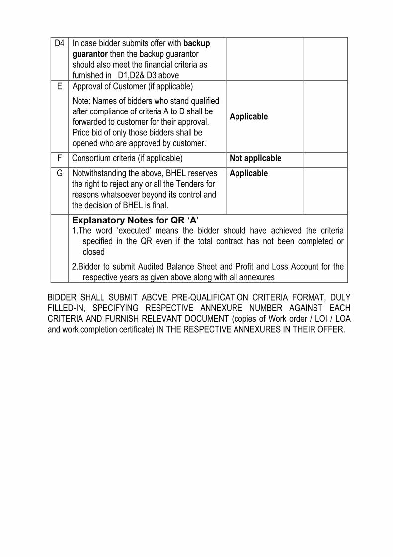
D4 In case bidder submits offer with backup guarantor then the backup guarantor should also meet the financial criteria as furnished in D1,D2& D3 above
E Approval of Customer (if applicable)
Note: Names of bidders who stand qualified after compliance of criteria A to D shall be forwarded to customer for their approval. Price bid of only those bidders shall be opened who are approved by customer.
Applicable
F Consortium criteria (if applicable) Not applicable
G Notwithstanding the above, BHEL reserves the right to reject any or all the Tenders for reasons whatsoever beyond its control and the decision of BHEL is final.
Applicable
Explanatory Notes for QR ‘A’ 1. The word ‗executed‘ means the bidder should have achieved the criteria
specified in the QR even if the total contract has not been completed or closed
2. Bidder to submit Audited Balance Sheet and Profit and Loss Account for the respective years as given above along with all annexures
BIDDER SHALL SUBMIT ABOVE PRE-QUALIFICATION CRITERIA FORMAT, DULY FILLED-IN, SPECIFYING RESPECTIVE ANNEXURE NUMBER AGAINST EACH CRITERIA AND FURNISH RELEVANT DOCUMENT (copies of Work order / LOI / LOA and work completion certificate) IN THE RESPECTIVE ANNEXURES IN THEIR OFFER.
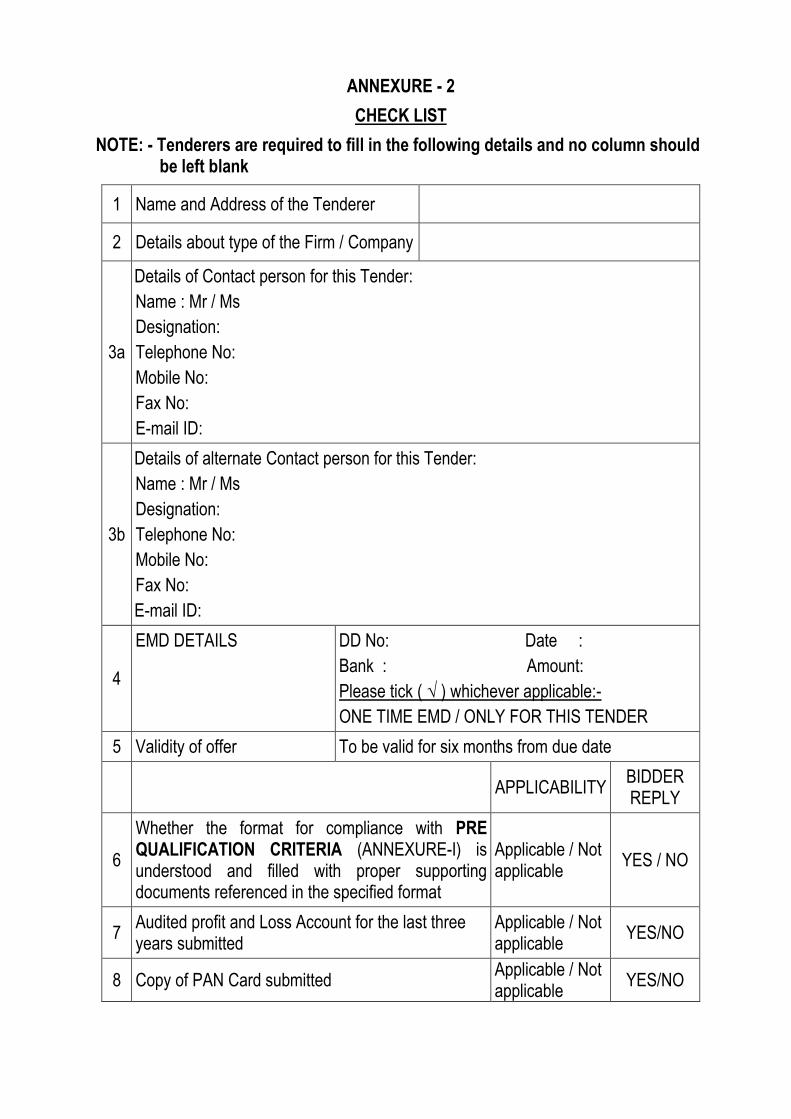
ANNEXURE - 2
CHECK LIST
NOTE: - Tenderers are required to fill in the following details and no column should be left blank
1 Name and Address of the Tenderer
2 Details about type of the Firm / Company
3a
Details of Contact person for this Tender:
Name : Mr / Ms
Designation:
Telephone No:
Mobile No:
Fax No:
E-mail ID:
3b
Details of alternate Contact person for this Tender:
Name : Mr / Ms
Designation:
Telephone No:
Mobile No:
Fax No:
E-mail ID:
4
EMD DETAILS DD No: Date :
Bank : Amount:
Please tick ( √ ) whichever applicable:-
ONE TIME EMD / ONLY FOR THIS TENDER
5 Validity of offer To be valid for six months from due date
APPLICABILITY BIDDER REPLY
6
Whether the format for compliance with PRE QUALIFICATION CRITERIA (ANNEXURE-I) is understood and filled with proper supporting documents referenced in the specified format
Applicable / Not applicable
YES / NO
7 Audited profit and Loss Account for the last three years submitted
Applicable / Not applicable
YES/NO
8 Copy of PAN Card submitted Applicable / Not applicable
YES/NO

9 Whether all pages of the Tender documents including annexures, appendices etc are read understood and signed
Applicable / Not applicable
YES/NO
10 Integrity Pact Applicable / Not applicable
YES/NO
11 Declaration by Authorised Signatory Applicable / Not applicable
YES/NO
12 No Deviation Certificate Applicable / Not applicable
YES/NO
13 Declaration confirming knowledge about Site Conditions
Applicable / Not applicable
YES/NO
14 Declaration for relation in BHEL Applicable / Not applicable
YES/NO
15 Non Disclosure Certificate Applicable / Not applicable
YES/NO
16 Bank Account Details for E-Payment Applicable / Not applicable
YES/NO
16 Capacity Evaluation of Bidder for current Tender Applicable / Not applicable
YES/NO
17 Tie Ups / Consortium Agreement are submitted as per format
Applicable / Not applicable
YES/NO
18 Power of Attorney for Submission of Tender / Signing Contract Agreement
Applicable / Not applicable
YES/NO
19 Analysis of Unit rates Applicable / Not applicable
YES/NO
20 Unquoted price bid submitted or not Applicable / Not applicable
YES/NO
NOTE: STRIKE OFF ‗YES‘ OR ‗NO‘, AS APPLICABLE DATE: AUTHORISED SIGNATORY
(With Name, Designation and Company seal)

ANNEXURE - 3
PRE QUALIFICATION CRITERIA -Technical:
Bidder should have executed erection and commissioning of STG works of at least one unit of minimum 30MW, in any Power Plant in the last seven year preceding the scheduled date of Bid submission.
The term ―Executed‖ means the unit should have been synchronized. OR
Bidder should have executed erection and commissioning of atleast one unit of Frame 6 GTG or mimimum one unit of 30MW capacity GTG in any Power Plant in the last seven year preceding the scheduled date of Bid submission.
The term ―Executed‖ means the unit should have been synchronized. OR
Bidder should have executed erection and commissioning of one unit of Frame V GTG / minimum 15MW capacity GTG / minimum 15MW capacity STG, in any Plant in the last seven years preceding the scheduled date of Bid submission, subject to providing the security of a Backup Guarantor as per the enclosed format / tender requirements.
The term ―Executed‖ means the unit should have been synchronized. OR
Bidder should have executed erection and commissioning of at least one unit of any one of the following three items, in any plant in the last seven year preceding the scheduled date of Bid submission, subject to providing the security of a Backup Guarantor as per the enclosed format / tender requirements
1) minimum rating 190MW Boiler / 570TPH Boiler 2) Chemical recovery Boiler of minimum rating 350 Tons of dry solids per day 3) HP piping of minimum rating 190MW in Power cycle piping package works.
The term ―Executed‖ means safety valve floating of the boiler should have been completed or the unit should have been synchronized.
Backup Guarantor MUST a) have executed at least one unit STG of minimum 190 MW of BHEL make
against order direct from BHEL, or one unit of Frame 9 GTG.
b) furnish a BG in the prescribed format, direct to BHEL, valid for the duration of the tendered works and equivalent to 10% of the bid amount in a SEALED cover.
c) also satisfy the assessment of Bidders capacity indicated for the Bidder in NIT and his performance in this project will also be assessed for loading purpose.
d) furnish a certificate that he has not provided back up in this tender to any other agency for this package.

e) also satisfy the financial criteria indicated for the bidder.
f) also attend the monthly reviews and be a joint signatory to monthly evaluation of progress.
g) function with the spirit of ensuring the performance of the bidder for successful completion of the scope of the works tendered.
h) On Completion of works, the experience of subject execution will be assigned to the bidder on whom the award has been placed. This bidder will be treated as eligible for the next higher group on his own strength.

TECHNICAL CONDITIONS OF CONTRACT (TCC)
Technical Conditions of Contract (Document no PS:MSC:TCC, Rev 00, 6th July 2010)
VOLUME – IA Part I & II
TECHNICAL CONDITIONS OF CONTRACT (TCC)
(Document No PS:MSX:TCC)
Rev 00 6th July 2010
BHARAT HEAVY ELECTRICALS LIMITED
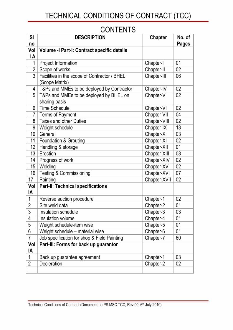
TECHNICAL CONDITIONS OF CONTRACT (TCC)
Technical Conditions of Contract (Document no PS:MSC:TCC, Rev 00, 6th July 2010)
CONTENTS
Sl no
DESCRIPTION Chapter No. of Pages
Vol I A
Volume -I Part-I: Contract specific details
1 Project Information Chapter-I 01
2 Scope of works Chapter-II 02
3 Facilities in the scope of Contractor / BHEL (Scope Matrix)
Chapter-III 06
4 T&Ps and MMEs to be deployed by Contractor Chapter-IV 02
5 T&Ps and MMEs to be deployed by BHEL on sharing basis
Chapter-V 02
6 Time Schedule Chapter-VI 02
7 Terms of Payment Chapter-VII 04
8 Taxes and other Duties Chapter-VIII 02
9 Weight schedule Chapter-IX 13
10 General Chapter-X 03
11 Foundation & Grouting Chapter-XI 02
12 Handling & storage Chapter-XII 01
13 Erection Chapter-XIII 08
14 Progress of work Chapter-XIV 02
15 Welding Chapter-XV 02
16 Testing & Commissioning Chapter-XVI 07
17 Painting Chapter-XVII 02
Vol IA
Part-II: Technical specifications
1 Reverse auction procedure Chapter-1 02
2 Site weld data Chapter-2 01
3 Insulation schedule Chapter-3 03
4 Insulation volume Chapter-4 01
5 Weight schedule-item wise Chapter-5 01
6 Weight schedule – material wise Chapter-6 01
7 Job specification for shop & Field Painting Chapter-7 60
Vol IA
Part-III: Forms for back up guarantor
1 Back up guarantee agreement Chapter-1 03
2 Decleration Chapter-2 02

TECHNICAL CONDITIONS OF CONTRACT (TCC)
Technical Conditions of Contract (Document no PS:MSC:TCC, Rev 00, 6th July 2010)
VOLUME- I A PART – I CHAPTER – I PROJECT INFORMATION
1 Name of the Project IOCL PARADIP 366MW CO-GENERATION CPP PACKAGE
2 Station Capacity 366 MW
3 Owner M/s Indian oil Corporation Ltd
4 Consultant M/s EIL
5 Site Location IOCL Paradip Refinery Project, Paradip Port Post, Orissa 754 141
6 Latitude 20 Degrees 15‘ 20‖
7 Longitude 86 Degrees 26‘ 00‖
8 MSL 3.91 IMSL
9 Nearest Highway 5A
10 Nearest Town / City Paradip
11 Nearest Railway Station Paradip
12 Nearest Air port Bhubaneshwar
13 Metrological Data
A) Temperature
i. Average Max Temperature 37 Deg C
ii. Average Min Temperature 16 Deg C
iii. Highest Max Temperature 42.4 Deg C
iv. Lowest Minimum Temperature 11.3 Deg C
v. Temperature to be considered
for design of Electrical Equipments / Devices
50 Deg C
B) Relative Humidity average 99.7%
C) Rainfall ( Average Annual ) Heavy
D) Wind Data – Summer 37-45 km/hr
Wind Data – Winter 15-26 km/hr
Wind Data –Cyclone 200-250 km/hr (S-SE)
Basic Wind speed for structural design
65 m/sec
E) Seismic Data Zone III
14 Languages spoken in the region English, Odiya
15 Language for communication with Sub- Contractor / Vendors
English
16 Tropicalisation
All Equipments supplied against this specification shall be given tropical and fungicidal treatment in view of climatic conditions prevailing at site
17 Supply Voltage 3 Phase 415 Volts
TECHNICAL CONDITIONS OF CONTRACT (TCC)
Technical Conditions of Contract (Document no PS:MSC:TCC, Rev 00, 6th July 2010)
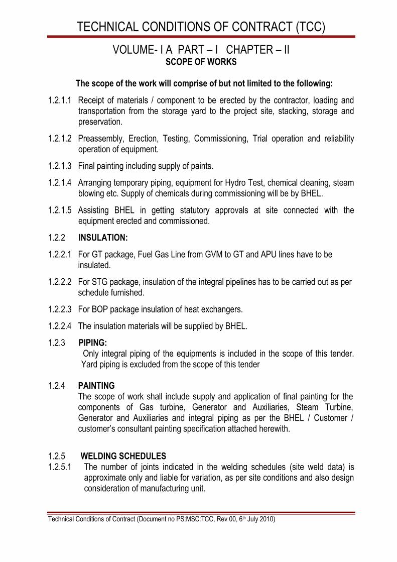
VOLUME- I A PART – I CHAPTER – II SCOPE OF WORKS
The scope of the work will comprise of but not limited to the following:
1.2.1.1 Receipt of materials / component to be erected by the contractor, loading and transportation from the storage yard to the project site, stacking, storage and preservation.
1.2.1.2 Preassembly, Erection, Testing, Commissioning, Trial operation and reliability operation of equipment.
1.2.1.3 Final painting including supply of paints.
1.2.1.4 Arranging temporary piping, equipment for Hydro Test, chemical cleaning, steam blowing etc. Supply of chemicals during commissioning will be by BHEL.
1.2.1.5 Assisting BHEL in getting statutory approvals at site connected with the equipment erected and commissioned.
1.2.2 INSULATION:
1.2.2.1 For GT package, Fuel Gas Line from GVM to GT and APU lines have to be insulated.
1.2.2.2 For STG package, insulation of the integral pipelines has to be carried out as per schedule furnished.
1.2.2.3 For BOP package insulation of heat exchangers.
1.2.2.4 The insulation materials will be supplied by BHEL.
1.2.3 PIPING: Only integral piping of the equipments is included in the scope of this tender.
Yard piping is excluded from the scope of this tender
1.2.4 PAINTING The scope of work shall include supply and application of final painting for the components of Gas turbine, Generator and Auxiliaries, Steam Turbine, Generator and Auxiliaries and integral piping as per the BHEL / Customer / customer‘s consultant painting specification attached herewith.
1.2.5 WELDING SCHEDULES 1.2.5.1 The number of joints indicated in the welding schedules (site weld data) is
approximate only and liable for variation, as per site conditions and also design consideration of manufacturing unit.

TECHNICAL CONDITIONS OF CONTRACT (TCC)
Technical Conditions of Contract (Document no PS:MSC:TCC, Rev 00, 6th July 2010)
1.2.5.2 The welding process, weld joint and material specification may change to suit site requirement.
1.2.5.3 The list is furnished only for estimation purpose. The contractor is not entitled for any additional payment even if there is any increase in quantum of welding.
1.2.5.4 The contractor shall weld the joints of site routing piping as per site requirement, no extra payment shall be made for such additional joints.
Note: FOR FURTHER DETAILED SCOPE OF WORKS REFER RELEVANT CHAPTERS IN THIS BOOK

TECHNICAL CONDITIONS OF CONTRACT (TCC)
Technical Conditions of Contract (Document no PS:MSC:TCC, Rev 00, 6th July 2010)
VOLUME- I A PART – I CHAPTER – III FACILITIES IN THE SCOPE OF CONTRACTOR / BHEL
(SCOPE MATRIX)
Sl.No Description
PART I
Scope to be taken care by Remarks BHEL Bidder
1.3.1.1.0 ESTABLISHMENT
1.3.1.1.1 FOR CONSTRUCTION PURPOSE:
A Open space for office Yes Chargeable basis at the prevailing rate.
B Open space for storage Yes
C Construction of bidder‘s office, canteen and storage building including supply of materials and other services
Yes
D Bidder‘s all office equipments, office / store / canteen consumables
Yes
E Canteen facilities for the bidder‘s staff, supervisors and engineers etc
Yes
F Fire fighting equipments like buckets, extinguishers etc
Yes
G Fencing of storage area, office, canteen etc of the bidder
Yes
1.3.1.1.2 FOR LIVING PURPOSES OF THE BIDDER
A Open space Yes
B Living accommodation Yes
1.3.1.2.0 ELECTRICITY
1.3.1.2.1 Electricity For construction purposes (to be specified whether chargeable or free)
1.3.1.2.1.1 Single point source Yes Chargeable basis at the prevailing rate.
1.3.1.2.1.2 Further distribution for the work to be done which include supply of materials and execution
Yes

TECHNICAL CONDITIONS OF CONTRACT (TCC)
Technical Conditions of Contract (Document no PS:MSC:TCC, Rev 00, 6th July 2010)
Sl.No Description
PART I
Scope to be taken care by Remarks BHEL Bidder
1.3.1.2.2 Electricity for the office, stores, canteen etc of the bidder which include:
Yes
1.3.1.2.2.1 Distribution from single point including supply of materials and service
Yes
1.3.1.2.2.2 Supply, installation and connection of material of energy meter including operation and maintenance
Yes
1.3.1.2.2.3 Duties and deposits including statutory clearances for the above
Yes
1.3.1.2.2.4 Living facilities for office use including charges
Yes
1.3.1.2.2.5 Demobilization of the facilities after completion of works
Yes
1.3.1.2.3 Electricity for living accommodation of the bidder‘s staff, engineers, supervisors etc on the above lines.(in case BHEL provides this facility, the scope should be given without ambiguity)
Yes
1.3.1.3.0 WATER SUPPLY
1.3.1.3.1 For construction purposes:
1.3.1.3.1.1 Making the water available at single point Yes Chargeable basis at the prevailing rate.
1.3.1.3.1.2 Further distribution as per the requirement of work including supply of materials and execution
Yes
1.3.1.3.2 Water supply for bidder‘s office, stores, canteen etc
1.3.1.3.2.1 Making the water available at single point Yes
1.3.1.3.2.2 Further distribution as per the requirement of work including supply of materials and execution
Yes

TECHNICAL CONDITIONS OF CONTRACT (TCC)
Technical Conditions of Contract (Document no PS:MSC:TCC, Rev 00, 6th July 2010)
Sl.No Description
PART I
Scope to be taken care by Remarks BHEL Bidder
1.3.1.4.0 LIGHTING
1.3.1.4.1 For construction work (supply of all the necessary materials)
At office storage area
At the preassembly area
At the construction site /area
Yes
1.3.1.4.2 For construction work (Execution of the lighting work / arrangements)
At office storage area
At the preassembly area
At the construction site /area
Yes
1.3.1.5.0 COMMUNICATION FACILITIES for site operations of the bidder
-
1.3.1.5.1 Telephone, Fax, internet, intranet, email etc
Yes
1.3.1.6.0 COMPRESSED AIR SUPPLY
1.3.1.6.1 Supply of Compressor and all other equipments required for compressor & compressed air system including pipes, valves, storage systems etc
- YES
1.3.1.6.2 Installation of above system and operation & maintenance of the same
- YES
1.3.1.6.3 Supply of the all the consumables for the above system during the contract period
YES
Sl.No Description
PART II
Scope to be taken care by Remarks
BHEL
Bidder
ERECTION FACILITIES
1.3.2.1.0 Engineering works for construction
1.3.2.1.1 Providing the erection drawings for all the equipments covered under this scope
Yes

TECHNICAL CONDITIONS OF CONTRACT (TCC)
Technical Conditions of Contract (Document no PS:MSC:TCC, Rev 00, 6th July 2010)
Sl.No Description
PART II
Scope to be taken care by Remarks
BHEL
Bidder
1.3.2.1.2 Drawings for construction methods Yes In consultati on with BHEL
1.3.2.1.3 As-built drawings – wherever deviations observed and executed and also based on the decisions taken at site- example – routing of small bore pipes
Yes Yes ,,
1.3.2.1.4 Shipping lists etc for reference and planning the activities
Yes Yes ,,
1.3.2.1.5 Preparation of site erection schedules and other input requirements
Yes ,,
1.3.2.1.6 Review of performance and revision of site erection schedules in order to achieve the end dates and other commitments
Yes
1.3.2.1.7 Weekly erection schedules based on
Sl No 1.3.2.1.5
Yes
1.3.2.1.8 Daily erection / work plan based on Sl No 1.3.2.1.7
Yes For daily monitoring meeting at
site
1.3.2.1.9 Periodic visit of the senior official of the bidder to site to review the progress so that works are completed as per schedule. It is suggested this review by the senior official of the bidder should be done once in every two months.
Yes
1.3.2.1.10 Preparation of preassembly bay Yes
1.3.2.1.11 Laying of racks for gantry crane if provided by BHEL or brought by the contractor/bidder himself
Not applicable

TECHNICAL CONDITIONS OF CONTRACT (TCC)
Technical Conditions of Contract (Document no PS:MSC:TCC, Rev 00, 6th July 2010)
1.3.3 LAND FOR SITE OFFICE
1.3.3.1 To establish a temporary site office, fabrication yard and storage area at the job site. The license fee payable shall be Rs. 20 per hundred square meters or part thereof, per month or part thereof, for any land made available to the CONTRACTOR within the provisions hereof and BHEL shall be entitled (without prejudice to any other mode of recovery), to recover license fee from the Running Account Bills / Final bill(s) of the CONTRACTOR and / or any other payments due to the CONTRACTOR from time to time under this or any other contract.
1.3.3.2 BHEL shall not provide to the contractor any residential accommodation to any of his staff and the contractor has to make his own arrangements.
1.3.3.3 Contractor has to furnish along with their offer, the details of requirements of area of space for his office, stores, storage shed.
1.3.3.4 Location and area requirement for office/storage sheds/ fabrication yard shall be discussed and mutually agreed to.
1.3.4 CONSTRUCTION WATER
1.3.4.1 Water shall be provided by BHEL on chargeable basis at one point. However bidder shall arrange for further distribution at their cost.
1.3.4.2 The cost of water supply shall be recovered from the Contractor‘s Running Account Bills at 0.25% of Running Account Bills/ Final bill value.
1.3.4.3 No separate payment shall be made for any contingency arrangement made by contractor, due to delay / failure of water supply.
1.3.5 CONSTRUCTION POWER
1.3.5.1 The construction power will be provided on chargeable basis at the applicable rate of IOCL at a single point and the further distribution is to be arranged by the bidder at his cost. Construction power shall be provided from the nearest Substation / tapping point on chargeable basis
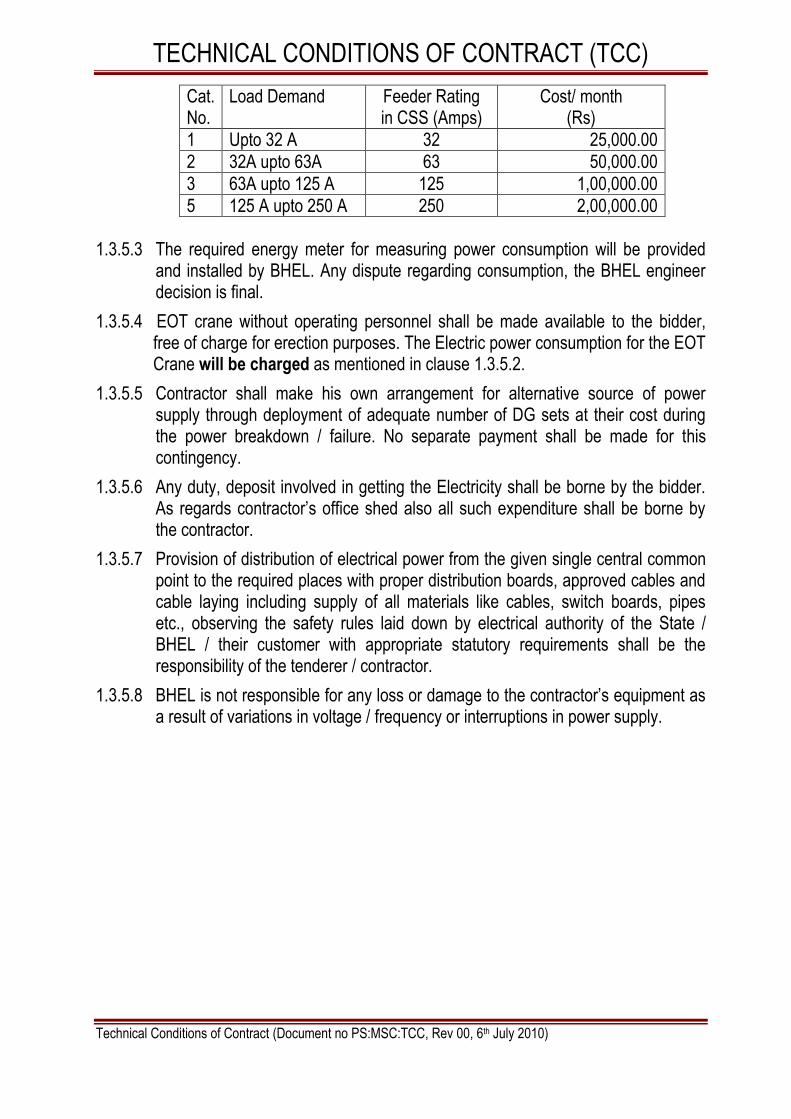
1.3.5.2 The cost of power supply shall be recovered from contractor‘s running account
bill as per the table given hereunder on Lumpsum basis based on the category of Load demand depending on their connected load.
The connected load in different categories as per each contractor load demand will be provided at 415 Volts through the following 4 assigned feeder categories in the compact sub-stations.
TECHNICAL CONDITIONS OF CONTRACT (TCC)
Technical Conditions of Contract (Document no PS:MSC:TCC, Rev 00, 6th July 2010)
Cat. No.
Load Demand Feeder Rating in CSS (Amps)
Cost/ month (Rs)
1 Upto 32 A 32 25,000.00
2 32A upto 63A 63 50,000.00
3 63A upto 125 A 125 1,00,000.00
5 125 A upto 250 A 250 2,00,000.00
1.3.5.3 The required energy meter for measuring power consumption will be provided
and installed by BHEL. Any dispute regarding consumption, the BHEL engineer decision is final.
1.3.5.4 EOT crane without operating personnel shall be made available to the bidder, free of charge for erection purposes. The Electric power consumption for the EOT Crane will be charged as mentioned in clause 1.3.5.2.
1.3.5.5 Contractor shall make his own arrangement for alternative source of power supply through deployment of adequate number of DG sets at their cost during the power breakdown / failure. No separate payment shall be made for this contingency.
1.3.5.6 Any duty, deposit involved in getting the Electricity shall be borne by the bidder. As regards contractor‘s office shed also all such expenditure shall be borne by the contractor.
1.3.5.7 Provision of distribution of electrical power from the given single central common point to the required places with proper distribution boards, approved cables and cable laying including supply of all materials like cables, switch boards, pipes etc., observing the safety rules laid down by electrical authority of the State / BHEL / their customer with appropriate statutory requirements shall be the responsibility of the tenderer / contractor.
1.3.5.8 BHEL is not responsible for any loss or damage to the contractor‘s equipment as a result of variations in voltage / frequency or interruptions in power supply.

TECHNICAL CONDITIONS OF CONTRACT (TCC)
Technical Conditions of Contract (Document no PS:MSC:TCC, Rev 00, 6th July 2010)
VOLUME- I A PART – I CHAPTER – IV T&PS and MMEs TO BE DEPLOYED BY CONTRACTOR
A: List of minimum major Tools & Plants to be deployed by the contractor
S no
Description Capacity Minimum quantity
remarks
1 Pick & Carry crane 8 T 01
2 Mobile crane 18 T or above
01
3 Trailer with prime mover 30/40 T 01
4 Hydraulic testing Pump (Manually operated) 01
5 Strand jack arrangement for erection of Steam turbine & its Generator
Adequate capacity
As required
NOTE:
1. The required civil works for erection of Steam turbine and steam turbine generator stators by strand jack method will be done by BHEL. If required, the bidder shall carryout strengthening of existing steel structure with their own labour, consumables, T&Ps etc. The required steel / scrap material as available at project site will be issued by BHEL at free of cost.
2. The stores for other than heavy items are located elsewhere (about 3 km away
from Erection Site) inside the Refinery compound. 3. For loading and transportation, all necessary T&P such as Trailers, Cranes,
Winches, welding generators, slings, jacks, sleepers, rails etc., are to be arranged by the contractor. All the tools & plants required for this scope of work, except the tools & plants provided by BHEL are to be arranged by the contractor within the quoted rates.
4. As there are bound to be interruptions in regular power supply, power cut / load
shedding in any construction site due to inherent power shortage in the state. It shall be the responsibility of the contractor to have minimum numbers of diesel operated welding generator sets to get urgent and important work to go on without interruptions. The consumables required to operate the generators are to be provided by the bidders at their cost.
5. Depending upon the nature of work and availability of facilities locally, contractor
may have to arrange for a temporary workshop for facilitating uninterrupted progress of work

TECHNICAL CONDITIONS OF CONTRACT (TCC)
Technical Conditions of Contract (Document no PS:MSC:TCC, Rev 00, 6th July 2010)
6. Lubricants and Experienced Crane operator for EOT crane to be arranged by the bidder at their cost.
7. All heavy items such as GT, Generator etc., unloaded at stores nearby to
foundation have to be transported to erection site. For loading and transportation, all necessary T&P such as Trailors, Cranes, Winches, welding generators, slings, jacks, sleepers, rails etc., are to be arranged by the contractor.
8. The availability of crane is likely to be hampered from time to time due to routine
preventive maintenance or breakdown maintenance. Contractor has to make alternative arrangement or plan / modify / alter his activities to suit the above conditions and the contractor will not be liable for any compensation or extension of time due to this non availability, for maintaining the erection schedule.

TECHNICAL CONDITIONS OF CONTRACT (TCC)
Technical Conditions of Contract (Document no PS:MSC:TCC, Rev 00, 6th July 2010)
VOLUME- I A PART – I CHAPTER - V T&Ps AND MMEs TO BE DEPLOYED BY BHEL ON SHARING BASIS
List of T&Ps to be made available by BHEL to contractor free of hire charges on sharable basis.
Sl. No
Description Qty
1 Acid Circulation pumps with necessary tanks, pipes, valves, instruments, fittings etc.
1 set
2 75 T or suitable higher capacity crane, as per requirement, at the discretion of BHEL
1 No.
3 Special tools and tackles supplied by BHEL Manufacturing Units
As required
4 EOT Crane in STG Hall - capacity 25 / 5T 1 No.
5 EOT Crane in BFP area -capacity 15 T 2 Nos.
6 Hydro-Test Pump 1 no
7 Temporary piping, Valves/ Pumps/ tanks etc. required for any commissioning requirement, at the discretion of BHEL
As required
Note:
1. The contractor has to arrange operator for EOT Crane. BHEL will arrange operator for other cranes in BHEL Scope except for EOT Crane.
2. Providing manpower assistance required for free movement of Trailing cable of EOT Crane is included in the scope of this contract.
3. BHEL crane (75 T or suitable higher capacity crane) will be available to contractor only after the contractor deploys all of the minimum T& Ps mentioned in sl no 1 and 2 of the table in chapter IV.
4. Crane operators deployed by the contractor shall be tested by BHEL before he is allowed to operate the cranes.
5. BHEL may provide either BHEL owned cranes or hired cranes at the discretion of BHEL.
In the event of providing BHEL Cranes: i) Fuel has to be arranged by the bidder at his cost. ii) Crane operator will be provided by BHEL

TECHNICAL CONDITIONS OF CONTRACT (TCC)
Technical Conditions of Contract (Document no PS:MSC:TCC, Rev 00, 6th July 2010)
In the event of providing hired cranes: The fuel charges shall be recovered as given below:
For 75 T crane: Rs. 120/hr For 150 T/ 135 T/100T crane: Rs 200 /hr For Heavy duty crane: Rs 250 /hr
6. Besides the T & P mentioned above, which is being made available to the contractor
on free of hire charges, any additional crane and other T & P which may be required for successful and timely execution of the work covered within the scope of this tender shall be arranged and provided at site by the contractor at his cost. In case if the contractor fails to provide such equipments, BHEL will arrange for the same and the cost will be recovered from the contractor‘s bill with BHEL overheads, as applicable from time to time which may vary even during contract period.
7. All the distribution boards, connecting cables, hoses etc., and temporary connection work including electrical connections for the BHEL issued T & Ps shall have to be arranged by the contractor at his cost.
8. Cranes are only for erection purpose and shall not be available for material handling or transportation purpose. Contractor shall make their own arrangements for material transportation to erection site.
9. The contractor at his cost shall arrange for grouting of anchor points of T & Ps issued to him. Necessary grout materials are to be arranged by the contractor at his cost.
10. For higher capacity crane, the required consolidation and preparation of ground and placing same (including civil work with material) is covered in the scope of contract. The scope includes raising the ground level by the 1 M.
11. Filling pump for hydro Test is to be arranged by the contractor, if required.
TECHNICAL CONDITIONS OF CONTRACT (TCC)
Technical Conditions of Contract (Document no PS:MSC:TCC, Rev 00, 6th July 2010)
VOLUME- I A PART – I CHAPTER-VI
TIME SCHEDULE
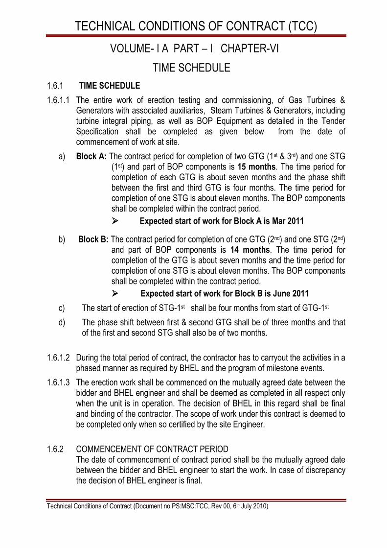
1.6.1 TIME SCHEDULE
1.6.1.1 The entire work of erection testing and commissioning, of Gas Turbines & Generators with associated auxiliaries, Steam Turbines & Generators, including turbine integral piping, as well as BOP Equipment as detailed in the Tender Specification shall be completed as given below from the date of commencement of work at site.
a) Block A: The contract period for completion of two GTG (1st & 3rd) and one STG (1st) and part of BOP components is 15 months. The time period for completion of each GTG is about seven months and the phase shift between the first and third GTG is four months. The time period for completion of one STG is about eleven months. The BOP components shall be completed within the contract period.
Expected start of work for Block A is Mar 2011
b) Block B: The contract period for completion of one GTG (2nd) and one STG (2nd) and part of BOP components is 14 months. The time period for completion of the GTG is about seven months and the time period for completion of one STG is about eleven months. The BOP components shall be completed within the contract period.
Expected start of work for Block B is June 2011
c) The start of erection of STG-1st shall be four months from start of GTG-1st
d) The phase shift between first & second GTG shall be of three months and that of the first and second STG shall also be of two months.
1.6.1.2 During the total period of contract, the contractor has to carryout the activities in a phased manner as required by BHEL and the program of milestone events.
1.6.1.3 The erection work shall be commenced on the mutually agreed date between the bidder and BHEL engineer and shall be deemed as completed in all respect only when the unit is in operation. The decision of BHEL in this regard shall be final and binding of the contractor. The scope of work under this contract is deemed to be completed only when so certified by the site Engineer.
1.6.2 COMMENCEMENT OF CONTRACT PERIOD
The date of commencement of contract period shall be the mutually agreed date between the bidder and BHEL engineer to start the work. In case of discrepancy the decision of BHEL engineer is final.

TECHNICAL CONDITIONS OF CONTRACT (TCC)
Technical Conditions of Contract (Document no PS:MSC:TCC, Rev 00, 6th July 2010)
1.6.3 MOBILISATION FOR ERECTION, TESTING, ASSISTANCE FOR COMMISSIOING ETC., The activities for erection, testing etc shall be started as per directions of Construction manager of BHEL.
The contractor has to augment his resources in such a manner that following major milestones of erection & commission are achieved on specified schedules:
Activity Milestones Month for first GTG
Milestones Month for first STG
Erection start Zero month (Expected start is Mar 2011 for Block-A and June 2011 for Block-B)
Zero month
GT alignment of GT & Generator
2nd month 4th month
Byepass stack erection completion
4th month 7th month
synchronisation 7th month 10th month
1.6.4 In order to meet above schedule in general, and any other intermediate targets
set, to meet customer / project schedule requirements, contractor shall arrange & augment all necessary resources from time to time on the instructions of BHEL.
1.6.5 In case any requirement is there to compress the schedule of activities to achieve project completion, then the additional expenses if any incurred will be discussed mutually and settled. BHEL decision in this regard is final and the issue is not arbitrable.
1.6.6 CONTRACT PERIOD The contract period for completion of entire work under scope shall be 15 (Fifteen) months for Block A and 14 (Fourteen) months for Block B from the ―COMMENCEMENT OF CONTRACT PERIOD‖ as specified earlier.
1.6.7 GUARANTEE PERIOD FOR EACH UNIT The guarantee period of twelve months shall commence from the date of
handing over of the Unit to Customer or six months from the date of first synchronisation of the set, whichever is earlier (Provided all erection, testing, and commissioning works are completed in all respects).

TECHNICAL CONDITIONS OF CONTRACT (TCC)
Technical Conditions of Contract (Document no PS:MSC:TCC, Rev 00, 6th July 2010)
VOLUME- I A PART – I CHAPTER-VII TERMS OF PAYMENT
1.7 Terms of payment : 1.7.1 A) Progressive Payment against monthly running bills for the erected items will be
made upto 90% of the accepted price for one GTG. The percentage break-up for the said 90% shall be as per Cl no 1.7.1.1 to 1.7.1.5 of the following table.
1.7.1.1 GAS TURBINE (35 %) % Rate schedule ID
A Foundation preparation and sole plate grouting 1.0 % GTG
B Placement of bearing pedestals 1.0 % GTG
C Placement of Gas Turbine 8.0 % GTG
D Placement of L.G.B and coupling 1.0 % GTG
E Placement of starting means 1.0 % GTG
F Placement of accessory modules 2.0% GTG
G Reaming, coupling & Alignment of GT, LGB and Generator & Starting means
4.0% GTG
H Erection of GT base enclosure 5.0% GTG
J Erection of off Lube oil & Fuel module including LO centrifuge
4.0% GTG
K GT vent fans & Exhaust frame cooler fans 2.0% GTG
L GT CO2 Racks & Sys 2.0% GTG
M Miscellaneous works on GT 4.0% GTG
1.7.1.2 DUCTING (Completion of all erection activities) (22 %)
A Inlet Filter Unit 6.0 % GTG
B Inlet Ducting inlet Silencer 2.0% GTG
C Exhaust Diffuser with expansion joints 1.0% GTG
D Exhaust Duct & By pass Duct/stack 8.0% GTG
E Support Structures 1.0% GTG
F Dampers with Seal air fans & System completion 4.0% GTG
1.7.1.3 GAS TURBINE GENERATOR (12%)
A Preparation of Foundation and leveling of Base Plates & packers etc. and grouting
1.0%
GTG
B Erection of Generator Stator 4.0% GTG
C Erection of bearings 1.0% GTG
D Rotor insertion (if separate, otherwise add to Generator erection)
2.0% GTG
E Erection of exciter, coupling and alignment 2.0% GTG
F Air coolers duct 2.0% GTG

TECHNICAL CONDITIONS OF CONTRACT (TCC)
Technical Conditions of Contract (Document no PS:MSC:TCC, Rev 00, 6th July 2010)
1.7.1.4 GAS COMPRESSOR & AUX (16%)
A Compressor, Gear box assly on Base frame with oil and gas piping around m/c
10.0% GTG
B Compressor drive motors 2.0% GTG
C Lub oil console and lub oil overhead tank 2.0% GTG
D All Coolers 2.0% GTG
1.7.1.5 COMMISSIONING of GTG ( 5%)
A Oil flushing completion (GTG) 1% GTG
B Cranking of GT 1% GTG
C Full Speed No Load 1% GTG
D Synchronisation 1% GTG
E Trial operation completion 1% GTG
1.7.1 B) Progressive Payment against monthly running bills for the erected items will
be made upto 90% of the accepted price for one STG. The percentage break-up for the said 90% shall be as per Cl no 1.7.1.6 to 1.7.1.9 of the following table.
1.7.1.6 STEAM TURBINE AND AUXILIARIES (40%) % Rate schedule ID
A Foundation Preparation and Matching, laying of packers 2.0% STG
B Placement of pedestals, base plates, leveling & tightening of foundation bolts
2.0% STG
C Placement of turbine with rotor and completion 8.0% STG
D Erection of emergency stop valve and control valves 2.0% STG
E Alignment of turbine rotor with generator 2.0% STG
F Grouting of turbine, generator and exciter with PGM 2.0 % STG
G Final alignment, coupling, reaming if required, fixing of coupling bolts & tightening
2.0% STG
H Final box up of bearing end covers etc. after oil flushing and cleaning of bearing pedestals
2.0% STG
J Erection of governing console 2.0% STG
K Erection of Gland Steam Condenser 2.0% STG
L Erection of Steam Jet Air Ejector 2.0% STG
M Turbine integral piping including all drains 4.0% STG
N Application of insulation for integral piping 1.0% STG
O Erection of Deaerators and FST, Alignment, Welding, etc. including platforms
5.0% STG
P Erection of LP Heater, IFO Heater 2.0% STG

TECHNICAL CONDITIONS OF CONTRACT (TCC)
Technical Conditions of Contract (Document no PS:MSC:TCC, Rev 00, 6th July 2010)
1.7.1.7 SURFACE CONDENSER (17%) STG
A Placement, Leveling & Alignment of Condenser Assembly 10.0% STG
B Alignment & welding of Hot Well with Condenser Assembly, Erection of all fittings
2.0% STG
C Hydro Test of condenser 3.0% STG
D Welding of condenser with turbine casing 2.0% STG
1.7.1.8 STEAM TURBINE GENERATOR AND EXCITER (28%) STG
A Foundation chipping, matching and leveling of base plates and packers
2.0% STG
B Generator stator placement, centering and leveling 10.0% STG
C Rotor insertion and completion of alignment 5.0% STG
D Erection of exciter 4.0% STG
E Alignment of generator with exciter 3.0% STG
F Erection of Coolers and other auxiliaries 4.0% STG
1.7.1.9 COMMISSIONING OF STG (5%) STG
A Oil Flushing 1% STG
B Steam Blowing 1% STG
C Rolling 1% STG
D Synchronization 1% STG
E Trial Operation 1% STG
FOR BOP SYSTEMS: 1.7.1 C) Progressive Payment against monthly running bills for the erected items will
be made upto 90% of the accepted price for the BOP. The percentage break-up for the said 90% shall be as per Cl no 1.7.1.10 (given in following the table) and according to Cl no 1.7.1 D given below.
1.7.1.10 Description Percentage Rate schedule ID
A Fuel system 12% BOP
B Refinery Gas system for GTG 10% BOP
C Dosing systems 3% BOP
D Blow down system 15% BOP
E Feed water system 25% BOP
F Make-up water system 3% BOP
G Condensate system 3% BOP
H Cooling water system 7% BOP
J Black start cooling water System 2% BOP
K Diesel Generator Set 2% BOP
L Miscellaneous Equipments 8% BOP
TOTAL % 90%

TECHNICAL CONDITIONS OF CONTRACT (TCC)
Technical Conditions of Contract (Document no PS:MSC:TCC, Rev 00, 6th July 2010)
Note A: Each of the above percentage of BOP systems may be split up by the BHEL site-Incharge depending on the work content of each of the systems to make progressive payment to the contractor.
1.7.1 D) For BOP Equipment, the above percentages will be further sub divided as per
activities indicated below, wherever applicable.
1 Erection of equipments like pumps, motors, skids etc. 50%
2 Alignment of the equipment and ready for trial run 45%
3 Trial run of equipment alone individually 5%
1.7.2 Further 10 % payment on pro-rata basis common to all equipments for the erected
items covered under this contract shall be released on achievement of the following stage / milestones events.
A Application of final painting 4%
B Area cleaning, temporary structures cutting / removal and return of scrap 1%
C Punch list points / pending points liquidation 2%
D Material reconciliation 1%
E Completion of unit trial run 1%
F Completion of contractual obligations 1%
TOTAL 10%
1.7.3 In case any requirement is there to compress the schedule of activities to achieve
project completion, then the additional expenses if any incurred will be discussed mutually and settled. BHEL decision in this regard is final and the issue is not arbitrable.
Note B: 1 The Lump sum quoted value in the price bid shall include for the Variation
of +15% (Fifteen percent) in quantity for Erection Works In case of variation in weight beyond +15%, the quantity exceeding +15% of the tendered quantity will be paid at the average tonnage rate arrived at as mentioned in the price bid.
2 Recovery of Retention amount as per Cl. 2.22 of GCC. 3 RA bill payments as per Chapter-X of SCC. 4 Payment for the first running bill will be released only on production of the
following. i. PF Regn. No. ii. Labour License No. iii. Workmen Insurance Policy No. iv. Unqualified Acceptance for Detailed L.O.I. v. Initial 50% Security Deposit.

TECHNICAL CONDITIONS OF CONTRACT (TCC)
Technical Conditions of Contract (Document no PS:MSC:TCC, Rev 00, 6th July 2010)
VOLUME- I A PART – I CHAPTER VIII TAXES AND OTHER DUTIES
1.8.0 TAXES
1.8.1 Value Added Tax (VAT) for the works
1.8.1.1 Price quoted shall be exclusive of VAT (WCT) and service tax.
1.8.1.2 As per the Orissa Gazette Notification dt 13.1.2009, VAT (WCT) is exempted for the execution of Works Contract to IOCL, Paradeep Petroleum Refinery Project.
1.8.1.3 The bidder shall get registered with State VAT authorities and the registration certificate shall be forwarded to BHEL immediately after commencement of work. In case the bidder had already registered under respective State VAT, they must quote their registration Number and forward copy of Registration Certificate while submitting this tender.
1.8.1.4 The bidder shall quote very competitive price after taking into consideration of above points.
1.8.2.0 Service Tax
1.8.2.1. Price quoted shall be exclusive of Service Tax. The service tax as statutorily leviable and payable by the bidder under the provisions of service tax Law / Act shall be paid by BHEL as per bidder claim through various running bills. The bidder shall furnish proof of service tax registration with Central Excise Department specifying the name of services covered under this contract. Registration Certificate should also bear the endorsement for the premises from where the billing shall be done by the bidder on BHEL for this project. The bidder shall obtain prior consent of BHEL before billing the service tax amount.
1.8.3.0 Other Taxes & Levies
1.8.3.1 Any other taxes and duties (except VAT & Service Tax) if any, as applicable, viz. Entry Tax, Octroi, Licenses, Deposits, Royalty, Stamp Duty, other charges / levies, etc. prevailing / applicable on the date of opening of technical bids and any variation thereof during the tenure of the contract are in the scope of bidder. In case BHEL is forced to pay any such taxes, BHEL shall have the right to recover the same from the bidder either from running bills or otherwise as deemed fit.
1.8.4.0 New Levies / Taxes
1.8.4.1 In case Government imposes any new levy / tax after award of the work during the tenure of the contract, BHEL shall reimburse the same at actual on submission of documentary proof of payment subject to the satisfaction of BHEL that such new levy / tax is applicable to this contract..
TECHNICAL CONDITIONS OF CONTRACT (TCC)
Technical Conditions of Contract (Document no PS:MSC:TCC, Rev 00, 6th July 2010)
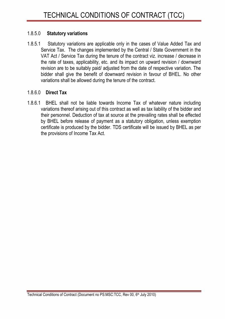
1.8.5.0 Statutory variations
1.8.5.1 Statutory variations are applicable only in the cases of Value Added Tax and Service Tax. The changes implemented by the Central / State Government in the VAT Act / Service Tax during the tenure of the contract viz. increase / decrease in the rate of taxes, applicability, etc. and its impact on upward revision / downward revision are to be suitably paid/ adjusted from the date of respective variation. The bidder shall give the benefit of downward revision in favour of BHEL. No other variations shall be allowed during the tenure of the contract.
1.8.6.0 Direct Tax
1.8.6.1 BHEL shall not be liable towards Income Tax of whatever nature including variations thereof arising out of this contract as well as tax liability of the bidder and their personnel. Deduction of tax at source at the prevailing rates shall be effected by BHEL before release of payment as a statutory obligation, unless exemption certificate is produced by the bidder. TDS certificate will be issued by BHEL as per the provisions of Income Tax Act.
TECHNICAL CONDITIONS OF CONTRACT (TCC)
Technical Conditions of Contract (Document no PS:MSC:TCC, Rev 00, 6th July 2010)
VOLUME- I A PART – I CHAPTER - IX WEIGHT SCHEDULE
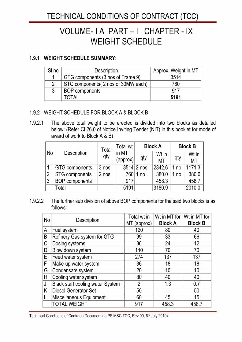
1.9.1 WEIGHT SCHEDULE SUMMARY:
Sl no Description Approx. Weight in MT
1 GTG components (3 nos of Frame 9) 3514
2 STG components( 2 nos of 30MW each) 760
3 BOP components 917
TOTAL 5191
1.9.2 WEIGHT SCHEDULE FOR BLOCK A & BLOCK B
1.9.2.1 The above total weight to be erected is divided into two blocks as detailed below: (Refer Cl 26.0 of Notice Inviting Tender (NIT) in this booklet for mode of award of work to Block A & B)
No Description Total qty
Total wt in MT (approx)
Block A Block B
qty Wt in MT
qty Wt in MT
1 GTG components 3 nos 3514 2 nos 2342.6 1 no 1171.3
2 STG components 2 nos 760 1 no 380.0 1 no 380.0
3 BOP components 917 458.3 458.7
Total 5191 3180.9 2010.0
1.9.2.2 The further sub division of above BOP components for the said two blocks is as
follows:
No Description Total wt in
MT (approx) Wt in MT for
Block A Wt in MT for
Block B
A Fuel system 120 80 40
B Refinery Gas system for GTG 99 33 66
C Dosing systems 36 24 12
D Blow down system 140 70 70
E Feed water system 274 137 137
F Make-up water system 36 18 18
G Condensate system 20 10 10
H Cooling water system 80 40 40
J Black start cooling water System 2 1.3 0.7
K Diesel Generator Set 50 -- 50
L Miscellaneous Equipment 60 45 15
TOTAL WEIGHT 917 458.3 458.7

TECHNICAL CONDITIONS OF CONTRACT (TCC)
Technical Conditions of Contract (Document no PS:MSC:TCC, Rev 00, 6th July 2010)
1.9.3 WEIGHT DETAILS OF GTG- 3 nos, STG-2 nos & BOP components
Description Weight in
tons
Rate schedule ID
GTG
a) Gas Turbibne Fr-9E Flange to Flange (3 Nos.) 690.000 GTG
b) Accessary Package (accessory Base) (3 Nos.) 180.000 GTG
c) Exhaust Plenum (3 units) 35.000 GTG
d) Diffuser (3 Nos.) 25.000 GTG
f) Field Inter Connection Piping (3 units) 96.000 GTG
g) Enclosure Accessory, GT & Generator Compartment (3 Nos) 300.000 GTG
h) Vent Fans ( 3 units) 30.000 GTG
j) Inlet Duct (3 units) 260.000 GTG
k) Exhaust Duct (3 units) 375.000 GTG
l) Vent Ducting (3 units) 75.000 GTG
m) Piping arrangement Lube Oil Junction boxes (3 units) 36.000 GTG
n) GT inlet air filter house (3 units) 390.000 GTG
o) Unit aux MCC (3 Nos ) 36.000 GTG
p) Other items (3 units) 176.000 GTG
ELECTRICAL MACHINES LIKE GENERATOR, ROTOR 810.000 GTG
TOTAL WEIGHT FOR 3 GTG 3514.000
STG
TURBINE 168.100 STG
GENERATOR STATOR ROTOR, EXCITER 157.700 STG
HEAT EXCHANGER COMPONENTS 434.360 STG
TOTAL WEIGHT FOR 2 STG 760.000
BOP
Fuel system 120.000 BOP
Refinery Gas system for GTG 99.000 BOP
Dosing systems 36.000 BOP
Blow down system 140.000 BOP
Feed water system 274.000 BOP
Make-up water system 36.000 BOP
Condensate system 20.000 BOP
Cooling water system 80.000 BOP
Black start cooling water System 2.000 BOP
Diesel Generator Set 50.000 BOP
Miscellaneous Equipment 60.000 BOP
TOTAL WEIGHT BOP 917.000 BOP

TECHNICAL CONDITIONS OF CONTRACT (TCC)
Technical Conditions of Contract (Document no PS:MSC:TCC, Rev 00, 6th July 2010)
1.9.4 WEIGHT SCHEDULE DETAILED
SHIPPING WEIGHTS AND DIMENSION
A PROJECT : 3 X Fr 9E, IOCL PARADIP
Doc No: GTEK/W&D/FR9/IOCLP/10
Sl No
DESCRIPTION Qty
Weight of shipment kg(each turbine)
Dimensions of box (Length x Width x Height)
(m) / Volume m3
TOTAL WEIGHT
(Kg)
Total Qty
Rate schedule ID
1 Gas Turbine Fr-9E Flange to Flange
1 230,000 13.2 x 4.6 x 5 690,000.00 3 GTG
2 Accessory Package (Accessory Base)
1 60,000 8.4 x 3.4 x 4.8 180,000.00 3 GTG
3 Exhaust Frame Blowers
1 1,000 2.2 x 1.5 x 1.5 (2 Nos.) 3,000.00 3 GTG
4 Exhaust Plenum
1 4500 6 x 4 x 5 ( 2 Nos)- TOP 13,500.00 3 GTG
1 6500 6 x 4.5 x 4- LOWER 19,500.00 3 GTG
1 800 2.5 x 1 x 1-Loose items 2,400.00 3 GTG
5 Base Exhaust Plenum
1 2000 6.5 x 1.2 x 1 (2 nos) 6,000.00 3 GTG
6 Diffuser 1 8500 6.5 x 6.5 x 3 25,500.00 3 GTG
7 Lube oil centrifuge (see note 1)
1 2500 2.5 x 1.5 x 1.8 2,500.00 1 GTG
8 Load Coupling with Hardware
1 2850 4.5 x 1.5 x 1.1 8,550.00 3 GTG
9 Accessory Coupling & Hardware
1 500 2.2 x 1 x 1 1,500.00 3 GTG
10 Guard Coupling Accessory
1 300 1.5 x 1 x 1 900.00 3 GTG
11 Jacking Oil Skid (EM Engg)
1 1200 2.2 x 1.5 x 1.5 3,600.00 3 GTG
12 Piping Lube Oil Flush Field -
1 1200 6.5 x 1.5 x 1.5 3,600.00 3 GTG
13 Field Inter Connection Piping
1 32000 6.5 x 1.5 x 1.1 (10 nos) 96,000.00 3 GTG
14
Enclosure Accessory GT & Generator Compartment
1 100000 250cu m (In ~22 boxes) 300,000.00 3 GTG
15 Vent Fans
1
10,000
2.5 x 2.5 x 3.5 (2No.s) 3 GTG
1 1.8 x 1.8 x 2.0 (2No.s) 30,000.00 3 GTG
1 1.5 x 1.5 x 2.0(1No) 3 GTG

TECHNICAL CONDITIONS OF CONTRACT (TCC)
Technical Conditions of Contract (Document no PS:MSC:TCC, Rev 00, 6th July 2010)
16 Inlet Duct GTG
i) Inlet Plenum
Extension 1 1,500 4.5 x 2.3 x 3.0 (2 nos) 4,500.00 3 GTG
ii) Inlet duct
transition piece 1 9500 9.8x2.3x1.7 28,500.00 3 GTG
iii) Inlet Duct
Expansion Pieces 1 1,900 10 x 3.7 x 0.4 ( 2 nos.) 5,700.00 3 GTG
iv) Inlet Duct Elbow 1 11,100 10 x 3.7 x 3.8 33,300.00 3 GTG
v) Silencer 1 20,200 10 x 3.7 x 3.1 60,600.00 3 GTG
vi) Duct Pieces 1 6900 10 x 2.3 x 3.1 (2 nos) 20,700.00 3 GTG
vii) Support
Structure 1 35,000 10x2.5x2.5- 4nos 105,000.00 3 GTG
17 Exhaust Duct GTG
i) Vertical Duct Asse mbly FR9N-VD-1
1 6,455 6.72 x 3.435 x 3 (2 nos) 19,365.00 3 GTG
ii) Vertical Duct Ass embly FR9N-VD-2
1 6,455 6.72 x 3.435 x 3 (1 no.) 19,365.00 3 GTG
iii) Vertical Duct Ass embly FR9O-VD-3
1 7,648 6.72 x 3.435 x 3.508 (1 no.)
22,944.00 3 GTG
iv) Silencer Assembly FR9N-SLI
1 11,265 6.9 x 3.4 x 3.050 (2 nos) 33,795.00 3 GTG
v) Silencer Assem bly FR9N-SL2
1 11,238 6.9 x 3.4 x 3.050 (2 nos) 33,714.00 3 GTG
vi) Transition Duct Assembly FR9N-TIL
1 4,546 3.42 x 6.87 x 2 (1 no) 13,638.00 3 GTG
vii) Transition Duct Assembly FR9N-TIR
1 4,492 3.42 x 6.87 x 2 (1 no) 13,476.00 3 GTG
viii) Transition Duct Assembly FR9N-T2
1 9,058 6.63 x 3.31 x 3.52 (2 nos) 27,174.00 3 GTG
ix) Expansion Joints 1 2,000 6 x 4 x 0.4 (3 nos) 6,000.00 3 GTG
xi) Horizontal Duct GTG
HIU 1 9,335 6.5X3.3X4.0 I no 28,005.00 3 GTG
H I L 1 9,664 6.7X3.3X4.0 -lno. 28,992.00 3 GTG
H 2 1 7,040 6.7X3.5X2.8 (2 no) 21,120.00 3 GTG
HO U 1 5,664 4.2X2.8X2.8 (1 no) 16,992.00 3 GTG
HOL 1 6,062 4.2X3.4X2.8 (I no) 18,186.00 3 GTG
xii) Silencer panels 1 25,000 3. 1x6.1 xO.5 (16 nos) 75,000.00 3 GTG
18 Gas Valve Module 1 7000 3.6x2.4x 4 21,000.00 3 GTG
19 C02 Rack - Frames 1 4,000 3.5 x 1 x 2.5 (4 RACKS nos.)
12,000.00 3 GTG
CO2 Cylinders 1 12000 0.5x0.5x2.0- (79 nos) 36,000.00 3 GTG

TECHNICAL CONDITIONS OF CONTRACT (TCC)
Technical Conditions of Contract (Document no PS:MSC:TCC, Rev 00, 6th July 2010)
20 Lube Oil Demister 1 3,000 2.5 x 1,6 x 2.5 (1 no) 9,000.00 3 GTG
21 Vent ducting 1 25000 1.6x1.2x6 – 8 boxes 75,000.00 3 GTG
22 Portable lube oil drain pump (see note 1)
1 2000 1.6 x1.4x1.2- 1 no 2,000.00 1 GTG
23 Compressor Water Wash Skid (see note 1)
1 7000 8x3.5 x 3.2 7,000.00 1 GTG
24 Piping Arrangement Lube oil Junction Boxes
1 2000 6.0 x 1.5 x 1.1 (4 nos) 6,000.00 3 GTG
25 Piping Arrangement Lube oil Junction Boxes
1 12000
6.5x 1.2x I (3No.s) 36,000.00
3 GTG
1 6.0x l.5x 1.1 (2No.s) 3 GTG
26
Anchoring, Base Plates Positioning Blocks (Foundation Hardware-Concrete Embedments)
1 3350 1.2 x 1.5 x 3.5 10,050.00 3 GTG
27
Anchoring, Base Plates Positioning Blocks (Foundation Hardware Shims, Guide block etc)
1 1900 0.5 x 0.5 x 1.5 5,700.00 3 GTG
28
Anchoring, Base Plates Positioning Blocks (Angle 75x75x45000)
1 425
6 x 0.175 x 0.325 (7 nos) 1,275.00 3 GTG
1 3 x 0.175 x 0.325 (1 no) 1,275.00 3 GTG
29 GT inlet air Filter house
1 130000 10 X 3.5 X 3.5 (16Boxs) 390,000.00 3 GTG
30 GT Auxiliary panel 1 300 1 X 1 X 2.5 900.00 3 GTG
31 Haz gas monitor 1 50 0.2 X 0.4 X 0.2 150.00 3 GTG
32 Radiation shield assy.
1 200 0.8 x 0.8 x 0.6 600.00 3 GTG
33 Boroscope (see note 1)
1 225 1 x 1 x 1 225.00 1 GTG
34 Special Tools for GT Maintenance (Tools) (see note 1)
1 550 1 x 1 x 2.2 550.00 1 GTG
35 Special tools for GT maintenance(Tools chest) (see note 1)
1 500 1 x 1x 1 500.00 1 GTG

TECHNICAL CONDITIONS OF CONTRACT (TCC)
Technical Conditions of Contract (Document no PS:MSC:TCC, Rev 00, 6th July 2010)
36
Special tools for GT maintenance (Hyd. Torque wrench) (see note 1)
1 350 0.8 x 1 x 1 350.00 1 GTG
37
Special tools for GT maintenance (Tool kit major disassy) (see note 1)
1 820 1 x 1 x 2.2 820.00 1 GTG
38 Special tools for GT maintenance(Lifting beam) (see note 1)
1 4000 10 x 1.5 x 1 4,000.00 1 GTG
39 Rotor stand 1 2200 1.2 x 1.5 x 2.0 (2 nos) 6,600.00 3 GTG
40 Vibration monitoring system
1 50 1 x 1 x 1 150.00 3 GTG
41 MHAMS hard ware & software
1 100 1.5 x 1.5 x 1 (2 nos) 300.00 3 GTG
42 Unit Aux MCC 1 12000 13 x 1.4 x 2.5 36,000.00 3 GTG
43 125V DCDB 1 6000 8 x 1 x 2.5 18,000.00 3 GTG
SUBTOTAL 2,704,061.
00 GTG
NOTE: 1. These item are common for all GTs (i.e Only 1 No. of each of these is being supplied for the whole project)
B WEIGHT & DIMENSION SCHEDULE (STEAM TURBINE & AUXILIARIES)
PROJECT:IOCL- PARADIP REFINERY 350 MW CPP 2X30 STG
TURBINE TYPE :EHNK 50/56-3
S.N.NO. GA004
M/C.Nos :T-0950, T-0951
Sl no
DESCRIPTION Qty
Total Weight(Kg)
Dimensions of box (Length x Width x Height) (mm)
TOTAL WEIGHT
(Kg)
Total
Qty
Rate schedule ID
1 Turbine Assembly 1 58000 5800x5200x4800 116,000.00 2 STG
2 Lube Oil pump assembly 2 1600 2200x900x1050 3,200.00 4
STG
3 Emergency lube oil pump assembly 1 1200 2100x1600x650 2,400.00 2
STG
4 Jacking Oil pump assembly 1 400 1800x1800x1500 800.00 2
STG
5 Lube Oil accumulator
1 set 500 1500x500x1765 1,000.00
2 set
STG

TECHNICAL CONDITIONS OF CONTRACT (TCC)
Technical Conditions of Contract (Document no PS:MSC:TCC, Rev 00, 6th July 2010)
6 Lube Oil Purifier 1 1400 2000x2000x1800 2,800.00 2 STG
7 Main Lube Oil Tank 1 6000 4550x2700x4000 12,000.00 2 STG
8 Duolex Filter 1 950 2500x750x2000 1,900.00 2 STG
9 Overhead Lube Oil Tank 1 3000 3500x3500x3300 6,000.00 2
STG
10 Governing Console 1 500 1600x1600x1400 1,000.00 2 STG
11 Gear Box 1 10000 2200x2100x2000 20,000.00 2 STG
12 Coupling 1 500 1000x600x600 1,000.00 2 STG
SUBTOTAL 168,100.00
C WEIGHTS & DIMENSION SCHEDULE
ELECTRICAL MACHINES ENGINEERING
PRODUCT: 3 X FR-IX, G.T.G TYPE: TARI 1080-36P WORK ORDER-1029430600
Sl no
DESCRIPTION Qty
Total Weight (Kgs)
Dimensions of box (Length x Width x
Height) (mm)
TOTAL WEIGHT (Kgs)
Total
Qty
Rate schedule ID
1 Generator package 1 210000 9000X4100X4700 630,000.00 3 GTG
2 FOUNDATION ITMES(Loose Items) 1 8000 24,000.00 3 GTG
3 GENERATOR ENCLOSURE 1 8000 12600X5600X5100 24,000.00 3 GTG
4 EXCITER 1 7000 4600X2020X1803 21,000.00 3 GTG
5 MAINTENANCE WEIGHT (ROTOR) 1 37000 9000X1200X1200 111,000.00 3 GTG
SUBTOTAL 810,000.00
D WEIGHTS & DIMENSION SCHEDULE
ELECTRICAL MACHINES ENGINEERING
PRODUCT 30 MW STG TYPE: TARI 800-20P
PROJECT: 2X30MW STG, IOCL, PARADIP
Sl No
DESCRIPTION Qty
Total Weight (Kgs)
Dimensions of box (Length x Width x Height) (mm)
TOTAL WEIGHT (Kg)
Total Qty
Rate schedule ID
1 GENERATOR STATOR 1 52000 4500X3500X3300 104,000.00 2 STG
2 GENERATOR ROTOR 1 12000 6600X1000X1000 24,000.00 2 STG
3 FOUNDATION ITEMS (Loose Items) 1 5650 11,300.00 2
STG
4 BEARINGS 1 3200 1900X550X1250 6,400.00 2 STG
5 EXCITER 1 5000 3000X2000X2000 10,000.00 2 STG
6 AVR 1 1000 1000X1000X2300 2,000.00 2 STG
SUBTOTAL 157,700.00
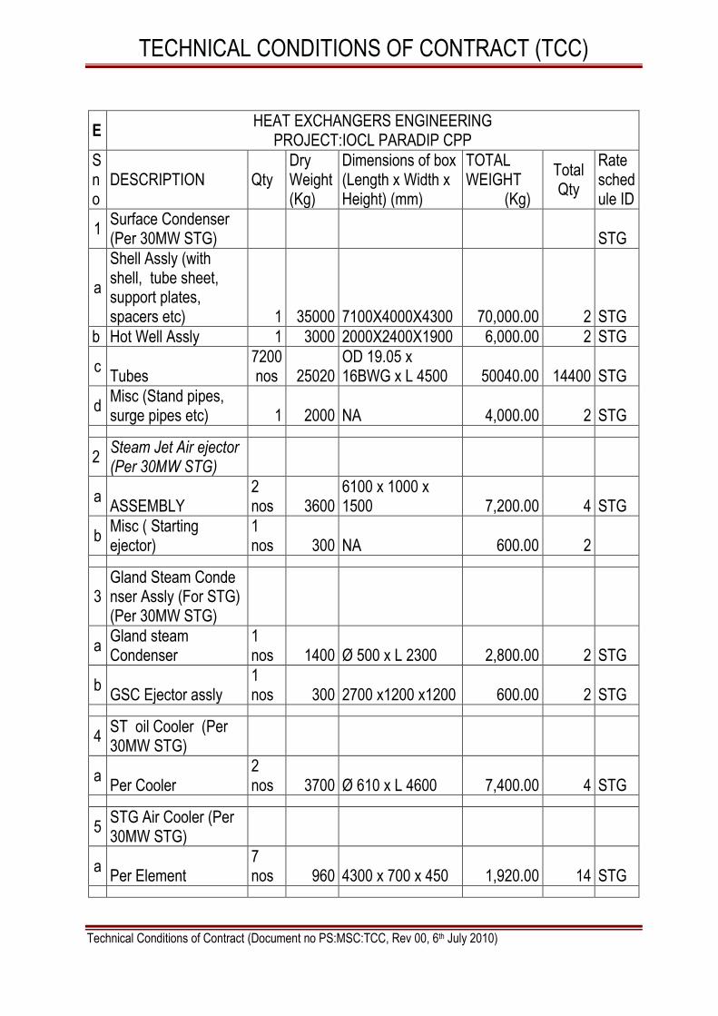
TECHNICAL CONDITIONS OF CONTRACT (TCC)
Technical Conditions of Contract (Document no PS:MSC:TCC, Rev 00, 6th July 2010)
E HEAT EXCHANGERS ENGINEERING
PROJECT:IOCL PARADIP CPP
Sno
DESCRIPTION Qty Dry Weight (Kg)
Dimensions of box (Length x Width x Height) (mm)
TOTAL WEIGHT (Kg)
Total Qty
Rate schedule ID
1 Surface Condenser (Per 30MW STG) STG
a
Shell Assly (with shell, tube sheet, support plates, spacers etc) 1 35000 7100X4000X4300 70,000.00 2 STG
b Hot Well Assly 1 3000 2000X2400X1900 6,000.00 2 STG
c Tubes
7200 nos 25020
OD 19.05 x 16BWG x L 4500 50040.00 14400 STG
d Misc (Stand pipes, surge pipes etc) 1 2000 NA 4,000.00 2 STG
2 Steam Jet Air ejector (Per 30MW STG)
a ASSEMBLY
2 nos 3600
6100 x 1000 x 1500 7,200.00 4 STG
b Misc ( Starting ejector)
1 nos 300 NA 600.00 2
3 Gland Steam Conde nser Assly (For STG) (Per 30MW STG)
a Gland steam Condenser
1 nos 1400 Ø 500 x L 2300 2,800.00 2 STG
b GSC Ejector assly
1 nos 300 2700 x1200 x1200 600.00 2 STG
4 ST oil Cooler (Per 30MW STG)
a Per Cooler
2 nos 3700 Ø 610 x L 4600 7,400.00 4 STG
5 STG Air Cooler (Per 30MW STG)
a Per Element
7 nos 960 4300 x 700 x 450 1,920.00 14 STG

TECHNICAL CONDITIONS OF CONTRACT (TCC)
Technical Conditions of Contract (Document no PS:MSC:TCC, Rev 00, 6th July 2010)
6 Spray cum Tray Deaerator (Total 2 nos required)
a Header
1 nos 20200
L 9.4 x W 3650 x H 3650 40,400.00 2 STG
b Feed Storage Tank (Sec-I)
1 nos 23200
L 11.3 x W 4350 x H 4600 46,400.00 2 STG
c Feed Storage Tank (Sec-II)
1 nos 22500
L 10.5 x W 4350 x H 4600 45,000.00 2 STG
c Feed Storage Tank (Sec-III)
1 nos 26150
L 12.5 x W 4350 x H 4600 52,300.00 2 STG
e Feed Storage Tank (Sec-IV)
1 nos 22000
L 10.5 x W 4350 x H 4600 44,000.00 2 STG
f Feed Storage Tank (Sec-V)
1 nos 22850
L 11.3 x W 4350 x H 4600 45,700.00 2 STG
g Loose items (for Stand pipes, Platform etc) 1 set 5000 10,000.00 2 set STG
SUBTOTAL 434,360.00
CONNECTED BOP PACKAGES.
The approximate detailed weights of ONLY some of the BOP components are listed in the following table. The approx weight of the balance BOP components may be referred from clause no 1.9.3 given above.
HEAT EXCHANGERS ENGINEERING
PROJECT:IOCL PARADIP CPP
Sl No
DESCRIPTION Qty Dry Weight (Kg)
Dimensions of box (Length x Width x Height) (mm)
TOTAL WEIGHT (Kg)
Total Qty
Rate schedule ID
1 Water to Water Heat Exchanger
A Per Cooler 1 nos 4000 L 5400 x W 700 x H 1100 12,000.00 3
BOP
2 HP Heater
A Per Cooler 1 nos 18000 Dia 1400 x L 7100 18,000.00 1 BOP
3 HPH Flash tank
A Per tank 1 nos 6600 Dia 2000 x H 4000 6,600.00 1 BOP SUBTOTAL 36,600.00

TECHNICAL CONDITIONS OF CONTRACT (TCC)
Technical Conditions of Contract (Document no PS:MSC:TCC, Rev 00, 6th July 2010)
SIZE AND WEIGHT SCHEDULE OF MAJOR
COMPONENTS OF BFP & BP
(a) HRSG Boiler Feed Pump & HRSG Booster Pump
Sl No
DESCRIPTION Qty
UNIT WEIGHT(Kg)
Dimension of box (Length x Width x Height) (mm)
Total Weight
(Kg)
Total
Qty
1 BFP Skid (Pump Assly. + Base Plate + tubing + Seal Coolers)
1 5770 2250 x 1000 x1050
23,080.00 4 BOP
2 BP Skid (Pump Assly. + Base Plate + tubing)
1 2550 1650 x 1200 x 950
10,200.00 4 BOP
3 Gear Box (DD). 1 1200 1150 x 1000 x 860
4,800.00 4 BOP
4 Suction Strainer at BP Suction (DD)
1 800 900 x 800 x 1400 3,200.00 4 BOP
5 BFP Recirculation valve (DD)
1 350 1800 x 550 x 1400
1,400.00 4 BOP
*6 Loose Items 3000 NA 3,000.00 BOP
SUBTOTAL 45,680.00
NOTE: * This is inclusive of Tools and Tackles (600 kg).
b UB MD BFP& UB MD Booster Pump
SL NO
DESCRIPTION Qty
UNIT WEIGHT(Kg)
Dimension of box (Length x Width x Height) (mm)
Total Weight
(Kg)
Total
Qty
1 BFP Skid (Pump Assly. + Base Plate + tubing + Seal Coolers)
1 5770 2250 x 1000 x1050
23,080.00 4 BOP
2 BP Skid (Pump Assly. + Base Plate + tubing)
1 2550 1650 x 1200 x 950
10,200.00 4 BOP
3 Gear Box (DD). 2 1200 1150 x 1000 x 860
2,400.00 4 BOP
4 Suction Strainer at BP Suction (DD)
1 800 900 x 800 x 1400 3,200.00 4 BOP
5 BFP Recirculation valve (DD)
1 350 1800 x 550 x 1400
1,400.00 4 BOP
*6 Loose Items 3000 NA 3,000.00 BOP
SUBTOTAL 43,280.00
NOTE: * This is inclusive of Tools and Tackles (600 kg).

TECHNICAL CONDITIONS OF CONTRACT (TCC)
Technical Conditions of Contract (Document no PS:MSC:TCC, Rev 00, 6th July 2010)
SIZE AND WEIGHT SCHEDULE OF MAJOR COMPONENTS FOR FUEL SYSTEM SKIDS
DESCRIPTION Qty Weig
ht (Kgs)
Dimension of box (Length x Width x Height) (m)
Total Weight (Kg)
Total
Qty
1 HSD 25 micron FILTER SKID
3 nos
3000 4X3X3 9,000.00 9 BOP
2 NAPHTHA 25 micron FILTER SKID
3 nos
3000 4X3X3 9,000.00 9 BOP
3 HSD 6 micron FILTER SKID
3 nos
3000 4X3X3 9,000.00 9 BOP
4 NAPHTHA 6 micron FILTER SKID
3 nos
3000 4X3X3 9,000.00 9 BOP
5 HSD 2.0 cubic meter FALSE START DRAIN TANK
3 nos
5000 0.9m (Dia)X 5 m(L)
15,000.00 9 BOP
6 NAPHTHA 2 cubic meter PURGE DRAIN TANK
3 nos
5000 0.9m (Dia)X 5 m(L)
15,000.00 9 BOP
7 LUBRICITY ADDITIVE DOSING SKID
3 nos
4000 4X3X3 12,000.00 9 BOP
8 HSD/NAPHTHA ACCUMULATORS
18 nos
1000 0.5(Dia) X 2 m(L) 3,000.00 54 BOP
9 LOOSE ITEMS PIPING NA 25,000.00 BOP
SUBTOTAL 106,000.00
WEIGHTS & DIMENSION SCHEDULE
(BFP DRIVE TURBINE & AUXILIARIES)
TURBINE TYPE :HNG32/23-3
S.N.NO. GA006
M/C.Nos :T-0948, T-0949
SL NO
DESCRIPTION Qty Total
Weight (Kg)
Dimensions of box (Length x Width x Height) (mm)
TOTAL WEIGHT (Kg)
Total Qty
1 Steam Turbine with base plate
1 17000 4100x3500x2500 34,000.00 2 BOP
2 Gear Box 1 700 800x100x800 1,400.00 2 BOP
3 Coupling 1 100 900x320x320 200.00 2 BOP
4 Lube oil tank 1 4225 3500x2450x2500 8,450.00 2 BOP
5 Overhead oil tank 1 712 1325x2500 1,424.00 2 BOP
6 Lube oil pump assembly
1 4750 3000x3500x800 9,500.00 2 BOP

TECHNICAL CONDITIONS OF CONTRACT (TCC)
Technical Conditions of Contract (Document no PS:MSC:TCC, Rev 00, 6th July 2010)
7 Duplex filter 1 124 625x600x725 248.00 2 BOP
8 Oil purification unit 1 1350 1250x1500x1100 2,700.00 2 BOP
9 Oil accumulator assembly
1 250 400x500x1800 500.00 2 BOP
10 Oil vapour Extraction fan assembly
2 100 500x400x500 200.00 4 BOP
11 Governing console 1 625 1200x1200x1400 1,250.00 2 BOP
SUBTOTAL 59,872.00
Sl No
Equipment /Package Description Qty Dimension (each)
L x B x H (M)
Weight (each) Tons
1. PUMPS BOP
a. HP Export Feed Water Pumps BOP
i) 235 M3/Hr Feed Pumps For HP FW
Export To Refinery (Motor driven) 2 8M x 2.5M x 2.5M 18 BOP
ii) LO Skid for HP FW Export Pump 2 3M x 1.6M x 1M 2 BOP
iii) 235 M3/Hr Feed Pumps For HP FW
Export To Refinery (turbine driven) 1 8M x 2.5M x 2.5M 12 BOP
b. MP Export Feed Water Pumps BOP
i) 125 M3/Hr Feed Pumps For MP FW
Export To Refinery (Motor driven) 2 5M x 2M x 2M 12 BOP
ii) LO Skid for MP FW Export Pump 2 3M x 1.6M x 1M 2 BOP
iii) 125 M3/Hr Feed Pumps For MP FW
Export To Refinery (Turbine driven) 1 5M x 2M x 2M 9 BOP
c. 395 M3/Hr MUH Transfer Pumps with Motors
3 5M x 2M x 1M 4 BOP
d. 74 M3/Hr Condenser Extraction Pumps with Motors
4 0.75M x 0.75M x 5M 2 BOP
e. 600 M3/Hr Condensate Transfer Pumps (Motor driven)
2 4M x 2.5M x 1M 5 BOP
f. 600 M3/Hr Condensate Transfer Pumps (Turbine driven)
1 4M x 2.5M x 1M 2 BOP
g. 350 M3/Hr Black Start ACW Pumps (Motor Driven)
1 2M x 1M x 1M 2 BOP
h. Blow Down Transfer Pumps with motors
10 0.75M x 0.75M x 5.5M 0.5 BOP
i. Dewatering Pumps 4 0.5M x 0.5M x 0.55M 0.15 BOP
2. Dosing Systems
a. HP Dosing System (Tri-Sodium Phosphate) for HRSGs
3 4M x 2.5M x 3.5M 6 BOP

TECHNICAL CONDITIONS OF CONTRACT (TCC)
Technical Conditions of Contract (Document no PS:MSC:TCC, Rev 00, 6th July 2010)
b. LP Dosing System (Hydrazine) for De-aerator
1 4M x 2.5M x 3.5M 6 BOP
c. LP Dosing System (Ammonia) for De-aerator
1 4M x 2.5M x 3.5M 6 BOP
d. LP Dosing System (Ammonia) for Condensate Storage Tank
1 4M x 2.5M x 3.5M 6 BOP
3. Electric hoists for material handling in miscellaneous areas
7 Capacity – 3T each
BOP
4. Under-slung single girder crane 1 Capacity – 3T BOP
5. Chain Pulley Blocks for material handling in miscellaneous areas
5 Capacity- 3T - 1 no Capacity- 2T- 2nos Capacity- 5T- 2nos
BOP
6 Motor for Motor Driven UB BFP & BP
2 BOP
7 Steam Turbine Driven UB BFP 2 BOP
8 Motor for Motor Driven HRSG BFP & BP
4 BOP
Note:
1) The product/ equipment list and weight indicated in this chapter is indicative and for estimation purpose only.
2) There is likelihood of addition of any products / equipment integral to GTG / STG, other than those indicated above. The Quoted / Accepted Rates shall be applicable for such products also. Decision of BHEL in this regard will be final and binding on the contractor.

TECHNICAL CONDITIONS OF CONTRACT (TCC)
Technical Conditions of Contract (Document no PS:MSC:TCC, Rev 00, 6th July 2010)
VOLUME- I A PART –I CHAPTER -X GENERAL
1.10.1 All the works such as cleaning, leveling, aligning, trial assembly, dismantling of certain components for checking and cleaning, surface preparation, fabrication of sheets, tubes and pipes as per general engineering practice and as per BHEL Engineer‘s instructions at site, cutting, weld depositing, grinding, straightening, chamfering, filing, chipping, drilling, reaming, scrapping, lapping, fitting-up etc., as may be applicable in such erection works and are necessary to complete the work satisfactorily, shall be carried out by the contractor as part of the work with in the quoted rate. Major machining work, which is only to be carried out in workshops, will be arranged by BHEL.
1.10.2 The work shall conform to dimensions and tolerances given in various drawings and quality manuals provided by BHEL. If any portion of work is found to be defective in workmanship not conforming to drawings or other stipulations, the contractor shall dismantle and redo the work duly replacing the defective materials at his cost, failing which the job will be carried out by BHEL by engaging other agencies and recoveries will be effected from contractor‘s bill towards expenditure incurred including BHEL‘s overhead charges.
1.10.3 Contractor shall execute the work as per sequence and procedure prescribed by BHEL at site. The applicable erection manuals which are available with BHEL site office are to be referred for compliance and guidance before taking up the work. Any rework on this failure to comply with will be to account contractor only. BHEL engineer, depending upon the availability of materials, fronts etc, will decide the sequence of erection and methodology. No claims for extra payment from the contractor will be entertained on the grounds of deviation from the method of erection adopted in erection of similar jobs or for any reason whatsoever.
1.10.4 Contractor has to work in close co-ordination with other erection agency at site. BHEL engineer will co-ordinate area clearance. In a project of such magnitude, it is possible that the area clearance may be less/more at a particular given time. Activities and erection program have to be planned in such a way that the milestone are achieved as per schedule/ plans. Contractor shall arrange & augment the resources accordingly.
1.10.5 The contractor is strictly prohibited from using BHEL‘s regular components like angles, channels, beams, plates, pipe/tubes, and handrails etc for any temporary supporting or scaffolding works. Contractor shall arrange himself all such materials. In case of such misuse of BHEL materials, a sum as determined by BHEL engineer will be recovered from the contractor‘s bill. The decision of BHEL engineer is final and binding on the contractor.

TECHNICAL CONDITIONS OF CONTRACT (TCC)
Technical Conditions of Contract (Document no PS:MSC:TCC, Rev 00, 6th July 2010)
1.10.6 The contractor will be responsible for the safe custody and proper accounting of all materials in connection with the work. If the contractor has drawn materials in excess of design requirements, recoveries will be effected for such excess drawls at the rate prescribed by manufacturing units.
1.10.7 No member of the already erected structure/ platform, pipes, grills, platform, other component and auxiliaries should be cut without specific approval of BHEL engineer.
1.10.8 Contractors shall ensure that all their Staff / Employees are exposed to periodical training programme conducted by qualified agencies / personnel on ISO 9001 – 2000 Standards.
1.10.9 For other agencies, such as piping, cabling, instrumentation, insulation etc., to commence their work from / on the equipments coming under this scope, Contractor has to clear the front, expeditiously and promptly as instructed by BHEL Engineer. Some time it may be required to re-schedule the activities to enable other agencies to commence/continue the work so as to keep the over all project schedule.
1.10.10 The terminal points decided by BHEL are final and binding on the contractor for deciding the scope of work and effecting the payment for the work done up to the terminals.
1.10.11 Fire Barricade protection is to be done for the purpose of fire safety in the erection area (temporary but with steel structures and GI sheets covering for the fire protection for the unit under operation) as required by BHEL‘s customer / Consultant.
1.10.12 For the purpose of planning, contractor shall furnish the estimated requirement of power (month wise) for execution of work in terms of maximum KW demand.
1.10.13 On Completion of work, all the temporary buildings, structures, pipe lines, cable etc. shall be dismantled and leveled and debris shall be removed as per instruction of BHEL by the contractor at his cost. In the event of his failure to do so, the expenditure towards clearance of the same will be recovered from the contractor. The decision of BHEL Engineer in this regard is final.
1.10.14 If applicable, all piping layout drawings received from BHEL / Hydrabad for pipeline erection to be submitted to Boiler Inspector for approval. After approval of the above drawing, Erection of pipe line to be started.
1.10.15 All the necessary certificates and licenses required to carry out this scope of work are to be arranged by the contractor then and there at no extra cost.

TECHNICAL CONDITIONS OF CONTRACT (TCC)
Technical Conditions of Contract (Document no PS:MSC:TCC, Rev 00, 6th July 2010)
1.10.16 UTILITY POINTS
1.10.16.1 Number of utility points (Service / plant air, service / plant water, service / washing steam, inert gas (N2) etc., shall be indicated in the P & I diagram. Contractor to locate the utility points as advised by site engineer and shall route the piping to these points as per site conditions, and shall submit as built layout with B O M to BHEL for approval.
1.10.16.2 The utility points shall be located at convenient point to handle and to be
terminated with brass / bronze valve with suitable connection for hose pipe. 1.10.17 PLATFORMS, CROSSOVERS & CANOPIES
Platforms, ladders crossovers for sleepers and canopies shall be fabricated by contractor at site as per site engineer‘s advice within the quoted / accepted rate. Platforms shall also be provided at places where it has not been shown in drawings but if felt necessary by site engineer. Canopies shall be provided for all out door pumps and motors.
1.10.18 AS BUILT DRAWINGS
Contractor shall be supplied with two extra copies of the layout & drawings. Contractor to incorporate in one of the copy with Red ink all the changes / deviations / alterations etc carried out at site due to various reasons, with site engineer‘s endorsement. Marked up drawings shall be submitted to BHEL for approval.
1.10.19 SITE INSPECTION The owner/employer or his authorized agents may inspect various stages of
work during the currency of the contract awarded to him. The contractor shall make necessary arrangements for such inspection and carry out the rectification pointed out by the owner/employer without any extra cost to the owner / employer. No cost whatsoever such duplication of inspection of work be entertained.

TECHNICAL CONDITIONS OF CONTRACT (TCC)
Technical Conditions of Contract (Document no PS:MSC:TCC, Rev 00, 6th July 2010)
VOLUME- I A PART –I CHAPTER -XI FOUNDATIONS AND GROUTING
The scope of the work will comprise of but not limited to the following:
1.11.1 Foundation for the equipments to be erected shall be provided by BHEL/ clients of BHEL. The dimension of the foundation and anchor bolt pits shall be checked by the contractor for their correctness as per drawings. Further, top elevation of foundations shall be checked with respect to bench mark etc. All adjustments of foundations surfaces, enlarging the pockets in foundations etc. as may be required for the erection of equipments plants shall be carried out by the contractor.
1.11.2 Cleaning of foundation surfaces, pocket holes and anchor bolt pits etc., de-watering, making them free of oil, grease, sand and other foreign materials by soda wash, water wash, compressed air or any other approved methods etc., form/shuttering work are within the scope this work.
1.11.3 It shall be contractor‘s responsibility to check the various equipment foundations for their correctness with respect to level, orientation, dimensions etc., and ascertained dimensions shall be measured and submitted to BHEL for approval before erection. Also minor chipping, dressing of foundations up to 30 mm for obtaining proper face for packer plates/shims, and may be required for the erection of the equipment/plants will have to be carried out by the contractor without extra cost.
1.11.4 The surface of foundations shall be dressed to bring the surface of the foundations to the required level and smoothness prior to placement of equipments
1.11.5 Foundation pockets are to be cleaned thoroughly before placing the columns / equipments. Verticality of foundation bolts to be checked along with correctness of the threads and freeness of the nuts movement. If required cleaning of the threads to be done with proper dies.
1.11.6 The concrete foundation, surfaces shall be properly prepared by chipping, as required to bring the top of such foundation to the required level to provide the necessary roughness for bondage and to ensure enough bearing strength. All laitance and surface film shall be removed and cleaned and the packers placed with suitable mortar prior to erection of the equipment. Packer plates should not only be blue matched with foundation but also inter-packer contact surfaces between the packers and foundation frame etc., shall also be blue matched by Prussian Blue match checks and required percentage contact shall be achieved by chipping and scrapping as per BHEL Engineers instructions.

TECHNICAL CONDITIONS OF CONTRACT (TCC)
Technical Conditions of Contract (Document no PS:MSC:TCC, Rev 00, 6th July 2010)
1.11.7 All the equipment bases and structural steel bases and foundation pockets shall be grouted and finished as per this specification unless otherwise recommended by the equipment manufacturer.
1.11.8 The certificates of the grout is to be submitted BHEL. If necessary test cubes are to be made and tested at site to ensure the quality of the grout as per relevant IS standards. In case grouting with Portland cement is approved, necessary cement, sand etc to be arranged by the contractor including the fine aggregates.
1.11.9 All the materials required for grouting including special cements like Conbextra GPI,GP2, ACC- Shrinkkomb-N20, Sika Anckor, NSG/ NSG -1, CICO Excem GP, or its equivalent as approved by BHEL and other materials like Portland cement, sand etc., are to be arranged by the contractor at his cost. It shall be the responsibility of the contractor to obtain prior approval of BHEL, regarding suppliers, type of grouting cements before procurement of grouting cements.
1.11.10 Certain packer plates and shims over and above the quantity received as part of supplies from manufacturing units of BHEL will have to be cut out from steel plates / sheets at site by the contractor to meet site requirement. However machining of the packers, wherever necessary, will be arranged by BHEL at free of cost.
1.11.11 Works such as minor rectification of foundation bolts, reaming of holes, drilling of dowels, matching of bolts and nuts, making new dowel pin etc. are covered in the scope of work.
1.11.12 PROCEDURE FOR GROUTING :
Contractor has to carryout the grouting as per the work instructions for grouting available at site.
TECHNICAL CONDITIONS OF CONTRACT (TCC)
Technical Conditions of Contract (Document no PS:MSC:TCC, Rev 00, 6th July 2010)
VOLUME- I A PART –I CHAPTER -X II MATERIAL HANDLING AND SITE STORAGE
1.12.1 Loading at BHEL/Customer stores and storage yard, transport to site, unloading at site/working area of equipment placement on respective foundation/location, fabrication yard, pre-assembly bay or at working area are in the scope of work. The scope includes taking materials / Equipments from customer stores / storage yard also. Contractors Quoted / Accepted rate shall be inclusive of the same. Required cranes, tractors, trailer or trucks/ slings/ tools and tackles / labour including operators Fuel lubricants etc for loading & unloading of materials will be in the scope of contractor.
Note: The Stores is located at a distance of about 03 km from Erection
Site. 1.12.2 The equipments / materials from the storage yard shall be moved in sequence
to the actual site of erection /location at the appropriate time as per the direction of BHEL Engineer so as to avoid damage / loss of such equipment at site.
1.12.3 Sometimes it may become necessary for the contractor to handle certain
unrequired components in order to take out the required materials. The contractor has to take this contingency also into account. No extra payment is payable for such contingencies.
1.12.4 Materials shall be stacked neatly, preserved and stored in the contractor‘s shed
/ work area in an orderly manner. In case it is necessary to shift and re-stack the materials kept at work area / site to enable other agencies to carry out their work, same shall be done by the contractor at no extra cost.
1.12.5 All pipe and tube ends shall be covered with plastic caps or will be closed with
wooden plugs as the case may be.

TECHNICAL CONDITIONS OF CONTRACT (TCC)
Technical Conditions of Contract (Document no PS:MSC:TCC, Rev 00, 6th July 2010)
VOLUME- I A PART – I CHAPTER- XIII ERECTION
The scope of the work will comprise of but not limited to the following:
1.13.1 Gas / Steam Turbine received either Skid mounted or in loose assemblies with associated auxiliaries. Main part of generator may be supplied in three independent packages such as rotor, stator & Exciter.
1.13.2 Air filter, inlet ducting, exhaust ducting, guillotine damper and diverter damper, by-pass stack will be supplied in individual loose sections. Site job involves complete assembly, welding and erection.
1.13.3 Water wash skid shall involve welding of stainless steel pipe to and from skid. The piping shall be site routed.
1.13.4 Erection of all the piping systems supplied along with equipments, pumps and other auxiliaries covered in this contract is to be erected by the contractor with in the quoted rate.
1.13.5 Before erecting the valves and other mountings, check for the tag for correct rating with valve schedule. Ensure correct flow direction. Ensure easy accessibility for operation and maintenance of valves.
1.13.6 Normally the valves will have prepared edges for welding. But if it becomes necessary the contractor shall prepare new edges or recondition the edges by grinding or chamfering to match the corresponding tubes and pipes. All fittings like ―T‖ pieces , weld neck flanges, reducers etc., shall be suitably matched with pipes for welding.
1.13.7 The valves will have to be checked, cleaned or overhauled in full or in part before erection, after chemical cleaning and during commissioning. All the valves, after chemical cleaning, have to be checked, cleaned or over hauled in full or part before erection if called for as part of scope.
1.13.8 Normally weld neck valves will have prepared edges for welding. It may be occasionally necessary to prepare new edges, re-prepare the edges to suit site conditions, which shall be done by the contractor at no extra cost. All fittings like elbows, tees, reducers, flanges, inserts etc., shall be matched with pipes for welding which may required re-edge preparation, grinding etc., The valves will have to be checked, lapped or overhauled in full or in parts before erection / after chemical cleaning / during commissioning. Experienced technicians shall be arranged by the contractor at his own cost.
1.13.9 All the dampers, valves, lifting equipments, power cylinders, etc., shall be serviced and lubricated to the satisfaction of BHEL engineer before erecting
TECHNICAL CONDITIONS OF CONTRACT (TCC)
Technical Conditions of Contract (Document no PS:MSC:TCC, Rev 00, 6th July 2010)
the same and also during pre commissioning. The bearings of dampers shall be properly cleaned, serviced and lubricated before commissioning at no extra cost. Even after commissioning in the equipments, if there are problems in the operation they have to be attended by the contractor during the tenure of the contract.
1.13.10 Ducts / expansion pieces are dispatched to site in loose walls / plates and these are to be assembled at site before erection.
1.13.11 In the case of structural members / ducts in certain cases, the raw material will be supplied in random lengths and the contractor will have to make up the length / prepare the edges to suit the matching profiles, weld / bolt connect the joints at no extra cost.
1.13.12 The contractor shall fabricate piping, install lub oil systems and carry out the acid cleaning of fabricated piping. The contractor shall also service the lub oil system, carry out the hydraulic test of oil coolers. etc.,
1.13.13 Pipes above 2" diameter have to be cleaned by means of wire brush as per the instruction of BHEL Engineer and subsequently flushed with air before lifting them into position. For pipes below 2" diameter, shall be sponge cleaned with air flushing. After cleaning is over, the end caps shall be put back in tube openings till such time they are welded to other tubes. Required compressors shall be arranged by the contractor at his cost.
1.13.14 All the drain lines should have sufficient slope towards drain. Provide expansion loops in all the vents and drains as the drawings. All the valve packing with asbestos base to be lubricated once in 6 months till handing over. Necessary gland packing will be supplied by BHEL.
1.13.15 Attachment, welding of necessary instrumentation tapping points, thermocouple pads, root valves, condensing vessels, flow nozzles and control valves etc., both for regular measurements and performance testing to be provided on equiments / its auxiliaries or pipelines covered with in scope of this tender, will also be the responsibility of the contractor and the same will be done as per the instructions of BHEL Engineer. The erection and welding of all above items will be contractor‘s responsibility even if, the Items are supplied by an agency other than BHEL if they are integral to the scope envisaged under this package.
1.13.16 All attachment welding including those for insulation and refractory work coming on the pressure parts shall have to be done by the contractor. The hooks are suitable for stud welding machines. Contractor‘s quoted rate shall include all these contingencies. Attachment welding on pressure parts shall be done by qualified and certified welders only.

TECHNICAL CONDITIONS OF CONTRACT (TCC)
Technical Conditions of Contract (Document no PS:MSC:TCC, Rev 00, 6th July 2010)
1.13.17 Fine fittings, oil system and other small bore piping have to be routed according to site conditions and hence shall be done only in position as per the site requirement. Necessary sketch for routing these lines should be got approved from BHEL by the contractor. There is a possibility of slight change in routing the above pipelines when after completion, to suit the site conditions. The contractor should absorb this cost in his quoted rate.
1.13.18 Additional platforms for approaching different equipments as per the site requirement, which may not be indicated in drawings, shall be assembled and erected by contractor within the quoted price. The steel materials required for these works shall be supplied by BHEL free of cost and the contractor will have to install them to suit the requirement. Works of major nature are not covered under this clause.
1.13.19 Work such as minor rectification of foundation bolts, reaming of holes, drilling of dowels, matching of bolts and nuts, making new dowel pin, etc. are covered in the scope of work.
1.13.20 All hangers, supports and anchors (including concreting or welding) shall be installed as per drawing and complete the installation as per instructions of BHEL Engineer. Normally supports are issued in running meters. Any additional supports as called for by BHEL Engineer shall be fabricated by the contractor and provided at no extra cost. However, the raw material required for fabrication of such supports shall be supplied by BHEL free of cost. (Any machining or threading is involved will only be done by BHEL).
1.13.21 Suspension for piping etc., will be supplied in running lengths and shall be cut to suitable sizes and adjusted as required. Hangers‘ components which are being supplied in loose shall be assembled at site and erected as part of the work.
1.13.22 HSFG Bolts are to be tightened by turn of nut method / Torque Wrench, as per the instruction of BHEL Engineer. The bolted joints shall be jointly checked by BHEL / Customer and contractors personnel for the required tightness and retightened wherever necessary. The tightened bolts shall be identified by color paints. Facility for random checking with calibrated Torque Wrench shall also be provided by contractor.
1.13.23 Incase of any class of work for which there is no such specifications as laid down in the contract such us blue matching, welding of stainless steel parts etc., the work shall be carried out in accordance with instructions and requirements of the BHEL engineer at the quoted rates only.
1.13.24 All welded joints should be painted with anti corrosive paint, once radiography and stress relieving works are over.

TECHNICAL CONDITIONS OF CONTRACT (TCC)
Technical Conditions of Contract (Document no PS:MSC:TCC, Rev 00, 6th July 2010)
1.13.25 D.S.L / equivalent system for hoisting equipments are also to be erected and commissioned including load testing by the contractor within the quoted rates. Required manpower including electricians are to be arranged by the contractor for carrying out commissioning of electrical hoist and load testing of the above electrical hoist. Required loads will be provided by BHEL free of cost.
1.13.26 The temporary structures / items welded to permanent members / pipes are to be cut and removed without any damage. Any damage so to be made good by the contractor at his cost.
1.13.27 Before lifting the heavy components, soft materials like gunny bags to be used while lashing the rope to avoid dents, rubbing marks etc. The capacity, number of sheave pulleys, size of the rope, guide pulley locations are to be decided at site with respect to the capacity and positioning of the winch. The end caps provided at shop for various stubs are to be removed during final fit up only.
1.13.28 Prior to erection of any components inspection to be done for any foreign materials / damages and they are to be removed / attended as per BHEL engineer.
1.13.29 Wherever equipments are supplied in pre-fabricated assembled packages, there may be necessity to make minor changes, including strengthening by additional welds. This shall be treated as part of the contractor‘s scope.
1.13.30 All Rotating machineries and equipment shall be cleaned, lubricated, checked for their smooth rotation, if necessary dismantling and refitting before erection. If in the opinion of BHEL Engineer, the equipment is to be checked for clearance, tolerance at any stage of work or during commissioning period, all such works are to be carried out by contractor at his cost.
1.13.31 For skid mounted equipment, the checking and re-alignment required at site is in the scope of wok.
1.13.32 All the shafts of rotating equipment shall have to be properly aligned to those of matching equipment to perfection, accuracy as required and the equipment shall be free from excessive vibration so as to avoid overheating of bearings or other conditions which may tend to shorten the life of the equipment.
1.13.33 All the equipments / material to be taken inside the plant building shall be cleaned thoroughly before taking them inside and erect. The contractor shall clean, wherever necessary and paint inside surfaces of the equipments like coolers, oil tanks, Rubber expansion joints assemble and other components as per instruction of BHEL Engineer during erection at the quoted rate.
1.13.34 All the bearings, Gearboxes etc., of the equipment and electrical motors to be erected are provided with protective greases only. Contractor shall arrange as and when required by the engineer for cleaning the bearing/gear boxes etc., with

TECHNICAL CONDITIONS OF CONTRACT (TCC)
Technical Conditions of Contract (Document no PS:MSC:TCC, Rev 00, 6th July 2010)
kerosene or some other agent if necessary by dismantling some of the parts of the equipment during erection and shall arrange for re-greasing/lubricating them with recommended lubricants and assembling back. Lubricants will however be supplied by BHEL at free of cost.
1.13.35 All the motors / pumps shall be stripped opened, thoroughly serviced with proper care and re-assembled properly before erection by the contractor. During servicing, pre-commissioning & commissioning, if any deficiency is observed the same should be taken up with BHEL Engineer at site and rectified at site without any delay.
1.13.36 The contractor shall also carry out erection, testing, and commissioning of the oil centrifuge with in their quoted rate.
1.13.37 Certain instruments like pressure switches, gauges, air sets, regulators, filters, junction boxes, power cylinders, dial gauges, thermometers, flow meters, valve actuators, flow indicators etc., are received in assembled conditions as integral part of equipments. Contractor shall dismantle such instruments and re-erect whenever required prior to commissioning. Some time this may have to be handed over to store or instrumentation contractor.
1.13.38 Transportation of H2 and CO2 cylinders from the store and filling of the gas for generator stator cooling and protection system etc., as and when required till the unit is commissioned and handed over shall be the responsibility of the contractor. The cylinders are to be weighed before installation. Arrangements of weighing machine to be done by contractor.
1.13.39 All site-fabricated pipes will be issued in running metres as straight. These are to be cut and edge prepared at site to required length to suit layout as given in the erection drawing. All the attachments like lugs, stoppers, cleats etc., will be supplied as loose items and to be cut and welded to the pipes at site as per erection drawing necessary drilling of holes on main pipe for welding stubs shall also be done at site by the contractor. Fittings like bends, tees, elbow, mitre bends, reducers, flanges etc., will be supplied as loose items and the edge preparation if required shall be carried out by the contractor.
1.13.40 Tubes or pipes wherever deemed to be convenient will be sent in running lengths with sufficient bends. Contractor has to cut and edge prepare as per the standards / drawings and as per the instruction of BHEL Engineer. Bends up to NB 65 mm will have to be fabricated at site adopting specified heat treatment procedures, Wherever required at no extra cost.
1.13.41 Certain adjustments in length may be necessary while erecting pipelines and the contractor should remove the extra lengths / add extra lengths to suit the final layout after preparing edges afresh and adopting specified heat treatment procedure, are in the scope of work. For any mismatch while matching the joints

TECHNICAL CONDITIONS OF CONTRACT (TCC)
Technical Conditions of Contract (Document no PS:MSC:TCC, Rev 00, 6th July 2010)
in tubes, the cutting, adjusting, re welding, addition spool pieces should be done by the contractor to match site conditions without any extra payment.
1.13.42 Certain extra lengths of portions / parts of various fabricated ducts / components parts / bellows / piping etc. are provided as erection allowance and they shall have to be cut to suit site conditions and layout or certain length of portions/parts of ducts/components/bellows/piping casing etc., may have to be added to suit conditions and layouts. No extra payment will be admitted for such works.
1.13.43 Minor adjustment like removal of ovalities in pipes and opening or closing of the fabricated bends by process of heat correction or any other method approved by BHEL Engineer to suit the layout, with specified heat treatment procedure with in the quoted rate.
1.13.44 Contractor shall use only bolted clamps for achieving alignment of piping. Wherever "L" shaped stoppers and wedges are to be used for aligning piping and equipments, the same shall be subject to the approval of BHEL Engineer. Contractor shall remove the bridge, stopper etc., and not by hammer. Any burrs left on the equipments/piping, after welding, shall be ground off or any scar or cavity made good by welding and grinding. NDT tests shall be carried out if necessary to detect surface and sub-surface cracks in these ground areas.
1.13.45 Flame cutting of piping and other equipment shall be strictly done as per BHEL Engineer‘s instructions and in his presence only.
1.13.46 Incase of piping connected to equipment, matching of flanges for achieving the parallelism and alignment at equipment end by suitably resorting to heat correction or other method as instructed by BHEL Engineer is within scope of work.
1.13.47 All the oil & gas piping flanges, wherever provided are to be blue matched using surface plates for at least 80% contact area to attain leak proof of joints.
1.13.48 The surface of the pipes to be joined shall be suitably prepared as per instructions of BHEL Engineers. Edge preparation shall be done by chamfering machine, whenever required and all welding surfaces must be cleaned thoroughly. All works due to the mistake of the contractor shall be repaired / redone at contractor‘s cost. Instrumentation drains, stubs which are sent in loose from manufacturing units are to be welded at site as per BHEL Engineer‘s instructions.
1.13.49 Impulse piping wherever required for BHEL equipment is to be fabricated by the contractor including erection and welding of root valves as per the instructions of BHEL Engineer. The required piping and root valves will be supplied by BHEL free of cost.
TECHNICAL CONDITIONS OF CONTRACT (TCC)
Technical Conditions of Contract (Document no PS:MSC:TCC, Rev 00, 6th July 2010)
1.13.50 All the weld joints on equipments and piping shall be ground or filed after completion of welding and before radiography as per instructions of BHEL Engineer so as to achieve smooth surface to avoid of ripples, undulations etc.,
1.13.51 All piping items including pipes, valves, flanges, fittings etc. shall be supplied as commercially available. Hence Fit-ups, edge preparation including welding of stubs, shall be included in the contractor's scope.
1.13.52 Wherever elbows of 45 deg or any other angle are required, the same shall be cut from 90 deg. elbow supplied and used. No extra cost shall be paid.
1.13.53 The work on piping systems (air, water, oil, steam, gas etc.,) will include laying, edge preparation, fixing and welding of the elbows / fittings / valves etc., welded on the lines, fixing and adjustment of supports / hangers / shock absorbers and carrying out all other activities/works to complete the erection and also carrying out all pre-commissioning/commissioning operations mentioned in the specification as per BHEL Engineer's instructions and/or as per approved drawings/documents.
1.13.54 Flow nozzles, orifice, spray nozzles etc., shall be mounted/ erected after chemical cleaning/flushing/or steam blowing at site.
1.13.55 Erection of flow switches, steam traps, filters, flow meters, other metering elements, flow orifices, flow indicators, control valves supplied either by BHEL or customer forming part of the system is in the scope of work. This will include collecting from BHEL / Customer stores, transport to site, suitably cutting the erected piping, cleaning, erection, welding, radiography and stress relieving and commissioning.
1.13.56 Contractor shall also weld small length of piping with root valve to the pressure, flow and level tapping points on piping or flow nozzles/orifices/ metering elements fixed on piping as per the instructions of BHEL Engineer.
1.13.57 All drains/ vents/ relief/ escape/ safety valve piping to various tanks/ sewage/ drain canal/ flash box/ flash tank/ condenser/ sump/ atmosphere etc. from the stubs on the piping and equipments erected by the contractor is completely covered in the scope of work.
1.13.58 The contractor has to fabricate stainless steel orifice plate within the quoted rate. No extra payment will be made for fabrication of above orifice plates. The required stainless steel plate will be supplied by BHEL.
1.13.59 Welding of all thermo wells, stubs, hoses, tapping points, root valves, draft, pressure and temperature instrumentation points and all other instrumentation points on piping and auxiliaries and welding of thermocouple pads for permanent system are in the scope of work.
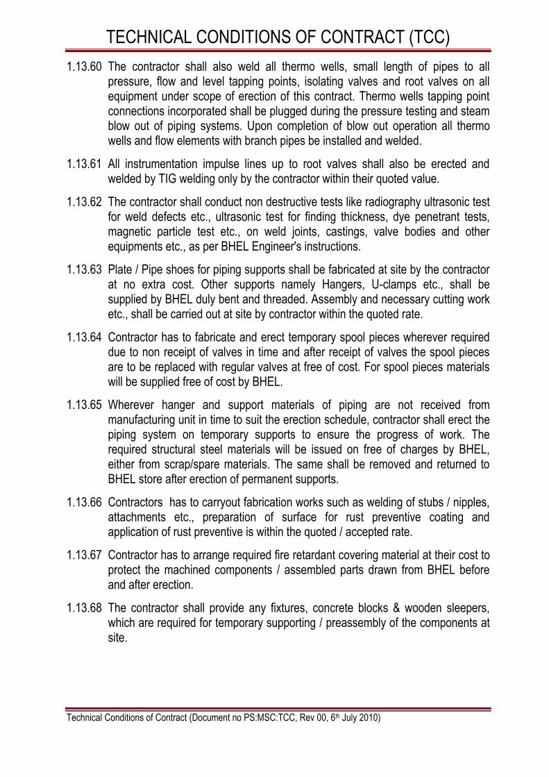
TECHNICAL CONDITIONS OF CONTRACT (TCC)
Technical Conditions of Contract (Document no PS:MSC:TCC, Rev 00, 6th July 2010)
1.13.60 The contractor shall also weld all thermo wells, small length of pipes to all pressure, flow and level tapping points, isolating valves and root valves on all equipment under scope of erection of this contract. Thermo wells tapping point connections incorporated shall be plugged during the pressure testing and steam blow out of piping systems. Upon completion of blow out operation all thermo wells and flow elements with branch pipes be installed and welded.
1.13.61 All instrumentation impulse lines up to root valves shall also be erected and welded by TIG welding only by the contractor within their quoted value.
1.13.62 The contractor shall conduct non destructive tests like radiography ultrasonic test for weld defects etc., ultrasonic test for finding thickness, dye penetrant tests, magnetic particle test etc., on weld joints, castings, valve bodies and other equipments etc., as per BHEL Engineer's instructions.
1.13.63 Plate / Pipe shoes for piping supports shall be fabricated at site by the contractor at no extra cost. Other supports namely Hangers, U-clamps etc., shall be supplied by BHEL duly bent and threaded. Assembly and necessary cutting work etc., shall be carried out at site by contractor within the quoted rate.
1.13.64 Contractor has to fabricate and erect temporary spool pieces wherever required due to non receipt of valves in time and after receipt of valves the spool pieces are to be replaced with regular valves at free of cost. For spool pieces materials will be supplied free of cost by BHEL.
1.13.65 Wherever hanger and support materials of piping are not received from manufacturing unit in time to suit the erection schedule, contractor shall erect the piping system on temporary supports to ensure the progress of work. The required structural steel materials will be issued on free of charges by BHEL, either from scrap/spare materials. The same shall be removed and returned to BHEL store after erection of permanent supports.
1.13.66 Contractors has to carryout fabrication works such as welding of stubs / nipples, attachments etc., preparation of surface for rust preventive coating and application of rust preventive is within the quoted / accepted rate.
1.13.67 Contractor has to arrange required fire retardant covering material at their cost to protect the machined components / assembled parts drawn from BHEL before and after erection.
1.13.68 The contractor shall provide any fixtures, concrete blocks & wooden sleepers, which are required for temporary supporting / preassembly of the components at site.

TECHNICAL CONDITIONS OF CONTRACT (TCC)
Technical Conditions of Contract (Document no PS:MSC:TCC, Rev 00, 6th July 2010)
VOLUME-I A PART–I CHAPTER-XIV PROGRESS OF WORK
1.14.1 Refer forms F -14 to F-18 of volume I D of volume -I book-II. Plan and review will be done as per the formats.
1.14.2 Contractor is required to draw mutually agreed monthly erection programs in consultation with BHEL well in advance. Contractor shall ensure achievement of agreed program and shall also timely arrange additional resources considered necessary at no extra cost to BHEL.
1.14.3 Progress review meetings will be held at site during which actual progress during the week vis-a-vis scheduled program shall be discussed for actions to be taken for achieving targets. Contractor shall also present the program for subsequent week. The contractor shall constantly update / revise his work program to meet the overall requirement. All quality problems shall also be discussed during above review meetings. Necessary preventive and corrective action shall be discussed and decided upon in such review meetings and shall be implemented by the contractor in time bound manner so as to eliminate the cause of nonconformities.
1.14.4 The contractor shall submit daily, weekly and monthly progress reports, manpower reports, materials reports, consumables (gases / electrodes) report, cranes availability report and other reports as per Performa considered necessary by the Engineer as per the format enclosed with this tender document.
1.14.5 The contractor shall submit weekly / fortnightly / monthly statement report regarding consumption of all consumables for cost analysis purposes.
1.14.6 The monthly report ending on 24th of every month shall be submitted as a booklet and shall contain the following details :-
a) Colour Progress photographs to accompany the report should be submitted.
b) Erection progress in terms of tonnage, welding joints, radiography, stress relieving, etc., completed as relevant to the respective work areas against planned.
c) Site Organization chart of engineers & supervisors as on 24th of the month with further mobilization plan
d) Category- wise man hours engaged during the previous month under the categories of fitters, welders, riggers, khalasis, grinder-men, gas-cutters,

TECHNICAL CONDITIONS OF CONTRACT (TCC)
Technical Conditions of Contract (Document no PS:MSC:TCC, Rev 00, 6th July 2010)
electricians, crane operators and helpers. Data will be spilt up under the work area of Boiler
e) Consumables report giving consumption of all types of gases and electrodes during the previous month.
f) Availability report of cranes
g) Safety implementation report in the format
h) Pending material and any other inputs required from BHEL for activities planned during the subsequent month.
1.14.7 The manpower reports shall clearly indicate the manpower deployed, category wise specifying also the activities in which they are engaged.
1.14.8 During the course of erection, if the progress is found unsatisfactory, or if the
target dates fixed from time to time for every milestone are to be advanced, or in the opinion of BHEL, if it is found that the skilled workmen like fitters, operators, technicians employed are not sufficient BHEL will induct required additional workmen to improve the progress and recover all charges incurred on this account including all expenses together with BHEL overheads from contractor‘s bills.
1.14.9 The contractor must obtain the signature and permission of the security
personnel of the customer for bringing any of their materials inside the sit premises. Without the Entry Gate Pass these materials will not be allowed to be taken outside.

TECHNICAL CONDITIONS OF CONTRACT (TCC)
Technical Conditions of Contract (Document no PS:MSC:TCC, Rev 00, 6th July 2010)
VOLUME- I A PART–I CHAPTER-XV WELDING
The scope of the work will comprise of but not limited to the following: 1.15.1 Welding of pressure parts, high tensile structural steel, Piping shall be done by
certified high pressure welders who posses valid certificate and who are approved by BHEL Engineer.
1.15.2 All welders including tack welders, structural and high pressure welder shall be tested and approved by BHEL Engineer before they are actually engaged on work even though they may possess a valid certificate. BHEL reserves the right to reject any welder if the welder's performance is not found to be satisfactory. The contractor shall maintain the records of qualification AND performance of welders. BHEL Engineer will issue all the welders qualified for the work, an identity card. The welder will keep the same with him at work place at all times. He may be stopped from work if he is not found in possession of the same.
1.15.3 Engineer may stop any welder from the work if his performance is unsatisfactory for any technical reason or if there is a high percentage of rejection in the joints welded by him. The welders having passed qualification tests does not absolve the contractor of contractual obligation to continuously check the welder's performance.
1.15.4 Faulty welds caused by the poor workmanship shall be cut and re-welded at the contractor‘s expense. The Engineer prior to any repair being made shall approve the procedure for the repair of defective welds. After the repair has been carried out, the compliance shall be submitted to the quality engineer.
1.15.5 All expenses for testing of contractor's welders including destructive and Non- destructive tests conducted by BHEL at site or at laboratory shall have to be borne by the contractor only. Limited quantity of tube and pipe material required for making test pieces will be supplied by BHEL free of cost.
1.15.6 Only BHEL approved electrodes and filler wire will be used. All electrodes shall be baked and dried in the electric electrode-drying oven to the required temperature for the period specified by the Engineer before these are used in erection work. All welders shall have electrodes drying portable oven at the work spot.
1.15.7 All welds shall be painted with anticorrosive red oxide paint once radiography and stress reliving works are over.

TECHNICAL CONDITIONS OF CONTRACT (TCC)
Technical Conditions of Contract (Document no PS:MSC:TCC, Rev 00, 6th July 2010)
1.15.8 Pre-heating, radiography and other NDT tests, post heating and stress relieving after welding, are parts of erection work and shall be carried out by the contractor in accordance with the instructions of the Engineer.
1.15.9 The contractor shall also be equipped for carrying out other NDT like LPI / MPI / Hardness test etc. as required as per welding schedules / drawings within the finally accepted price / rates. Ultrasonic testing, wherever required, will be arranged by contractor within the quoted rate.

TECHNICAL CONDITIONS OF CONTRACT (TCC)
Technical Conditions of Contract (Document no PS:MSC:TCC, Rev 00, 6th July 2010)
VOLUME-I A PART- I CHAPTER- XVI TESTING AND COMMISSIONING
The scope of the work will comprise of but not limited to the following:
1.16 TESTING , PRE – COMMISSIONING & COMMISSIONING AND POST COMMISSIONING
1.16.1 The Contactor shall carry out all the required tests and pre-commissioning and commissioning activities required for their successful and reliable operation.
1.16.2 All required tests (Mechanical and electrical) indicated by BHEL and their clients
for successful commissioning are included in the scope of these specifications.
These tests / activities may not have been listed in these specifications.
Specialized test equipment, if any, shall be provided by BHEL/ its client free of
hire charges. However contractor has to take proper care of the equipment
issued to him.
1.16.3 All the tests may have to be repeated till all the equipment satisfy the requirement
/ obligation of BHEL at various stages. The contractor shall do all the repairs for
site-welded joints arising out of the failure during testing.
1.16.4 The scope of pre-commissioning activities cover installation of all necessary
equipment including temporary piping, supports, valves, blanking, pumps, tanks,
with access platforms valves, along with accessories required for hydro test,
chemical cleaning, steam blowing or for any other tests. The scope also covers
the off site disposal of effluents.
1.16.5 It shall be the responsibility of the contractor to provide various categories of
workers in sufficient numbers along with Supervisors during pre commissioning,
commissioning and post commissioning of equipment and attending any problem
in the equipment erected by the contractor till handing over. The contractor will
provide necessary consumables, T&Ps, IMTEs etc., and any other assistance
required during this period. Association of BHEL‘s / Client's staff during above
period will not absolve contractor from above responsibilities.
1.16.6 It shall be specifically noted that the above employees of the contractor may
have to work round the clock along with BHEL Engineers and hence overtime
payment by the contractor to his employees may be involved. The contractors
finally accepted rates should be inclusive of all these factors also.

TECHNICAL CONDITIONS OF CONTRACT (TCC)
Technical Conditions of Contract (Document no PS:MSC:TCC, Rev 00, 6th July 2010)
1.16.7 In case, any rework is required because of contractor's faulty erection, which is noticed during pre-commissioning and commissioning, the same has to be rectified by the contractor at his cost. If any equipment / part is required to be inspected during pre-commissioning and commissioning, the contractor will dismantle / open up the equipment / part and reassemble / redo the work without any extra claim.
1.16.8 During commissioning, opening / closing of valves, changing of gaskets, Re-alignment of rotating and other equipment, attending to leakage and adjustments of erected equipment may arise. The finally accepted price /rates shall also include all such work.
1.16.9 The valves will have to be checked, cleaned or overhauled in full or in part before erection, after acid cleaning, steam blowing and during commissioning as may be necessary.
1.16.10 In case any defect is noticed during tests, trial runs and commissioning such as loose components, undue noise or vibration, strain on connected equipment etc., the contractor shall immediately attend to these defects and take necessary corrective measures. If any readjustment and re-alignment are necessary, the contractor at his cost shall do the same as per Engineer‘s instructions including repair, rectification and replacement work. The parts to be replaced shall be provided by BHEL.
1.16.11 The contractor shall carry out cleaning and servicing of valves and valve actuators prior to pre-commissioning tests and / or trial operations of the plant. A system for recording of such servicing operations shall be developed and maintained in a manner acceptable to BHEL Engineer to ensure that no valves and valve actuators are left un-serviced. Wherever necessary as required by BHEL Engineer, the contractor shall arrange to lap / grind valve seats.
1.16.12 Cleaning and servicing of all the filters / strainers, in the system shall be done by the contractor within the accepted price. All oils and greases to be filled in the main equipments as first fill and subsequent topping offs will be furnished by BHEL.
1.16.13 Transportation of oil drums from customer‘s BHEL‘s stores, filling of lubricants and filling of oil for flushing and first filling and subsequent topping up during commissioning and post commissioning is included in the scope of this contract. The contractor shall have to return all the empty drums to the customer / BHEL stores. Similarly transport of chemicals for various pre-commissioning activities / processes mentioned in the above clauses and returning of remaining and / or the empty containers of the chemicals to customer / BHEL stores is the responsibility of the contractor.

TECHNICAL CONDITIONS OF CONTRACT (TCC)
Technical Conditions of Contract (Document no PS:MSC:TCC, Rev 00, 6th July 2010)
1.16.14 Replacing / cleaning of filters of the erected equipments during pre-commissioning / commissioning stage are within the scope of work.
1.16.15 During the initial stages of work, trenches for draining water may not be available for alkali flushing or mass flushing for discharging and draining the system and piping. Necessary low point drains and temporary piping for this will have to be erected by contractor from materials provided by BHEL.
1.16.16 Contractor may have to replace old/damaged gaskets / packing etc. for equipments and the same shall be carried out by contractor as per requirement. Materials will be given by BHEL.
1.16.17 In case any erection defect is detected during various tests / operations trial runs as detailed above such as loose components undue noises or vibration strain on connected equipment steam or oil or water leakage etc. the contractor shall immediately attend these defects and take necessary corrective measures. The parts to be replaced shall be provided by BHEL free of cost. If the insulation is to be removed to attend any of the defects the cost of removal and reapplication of insulation should be borne by the contractor.
1.16.18 Necessary scaffolding and approaches for conducting the above shall also be within the scope of the contract.
1.16.19 The contractor shall carryout any other test as desired by BHEL Engineer on erected equipment covered under the scope of this contract during testing, pre-commissioning, commissioning, and operation, to demonstrate the completion of any part or whole work performed by the contractor.
1.16.20 Contractor shall cut / open works if needed, as per BHEL engineer‘s instructions during commissioning for inspection, checking and make good the works after inspection is over. This contingency shall be included within the quoted value. During commissioning opening of valves, changing of gaskets, attending to leakages, minor modification / rectification works may arise. The contractor has to carry out these works at his cost by providing required manpower in all the three shifts. In case any rework is required because of contractor‘s faulty erection and which is noticed during commissioning the same has to be rectified by the contractor at his cost.
1.16.21 Assistance for calibrating / testing the power cylinders / valves, gauges, instruments, etc. and setting to actuators shall be provided by contractor within the quoted rates.
1.16.22 Contractor to provide necessary commissioning assistance from pre-commissioning state onwards and up to continuous operation of the unit & handing over to customer. The category of personnel to be as per site requirement and to meet the various pre-commissioning and commissioning programmes made to achieve the schedule agreed with customer.

TECHNICAL CONDITIONS OF CONTRACT (TCC)
Technical Conditions of Contract (Document no PS:MSC:TCC, Rev 00, 6th July 2010)
1.16.23 After synchronization, the commissioning activities will continue. It shall be the responsibility of the contractor to provide manpower including necessary consumables, hand tools and supervision as part commissioning assistance.
1.16.24 It shall be specifically noted that the contractor and employees of the contractor may have to work round the clock during the pre-commissioning, commissioning and post-commissioning period along with BHEL Engineers / customer officials. Hence contractor‘s quoted rate shall take into consideration of all expenses that will be incurred for such arrangement of personnel including engineers / supervisors.
1.16.25 The valves, dampers, actuators etc. will have to be checked cleaned and overhauled in full or in part before erection, after acid cleaning, steam blowing and during commissioning as maybe necessary.
1.16.26 During commissioning any improvement / repair / rework / rectification / fabrication / modification due to design improvement / requirement is involved, the same shall be carried out by the contractor promptly and expeditiously.
1.16.27 Contractor at his cost shall lay all necessary temporary piping, install the pumps, blanks ,valves pressure gauges etc required for the test,. Contractor shall also lay the temporary pipelines with fittings, accessories and erection / commission pumps, tanks and other installations as instructed by BHEL Engineer for the purpose of chemical cleaning / alkali flushing / steam blowing / steam washing / steam flushing/water flushing / water washing/oil flushing etc., of piping and other equipments. Necessary, materials for this will be provided by BHEL. Temporary piping, fittings, accessories, pumps, valves, flanges, blanks etc shall be removed by him and returned to BHEL.
1.16.28 Chemical cleaning (Acid cleaning of piping / alkali flushing) will involve the installation of temporary piping, valves, cutting of some of the existing valves, placing the rubber for chemical and for mixing. Necessary temporary access platforms to mixing tank are to be made by the contractor. The dissolving tank, neutralizing tank etc. required for acid pickling will have to be fabricated by the contractor. Required materials will be provided by BHEL free of cost.
1.16.29 Overhauling / cleaning / servicing of valves, pumps, fittings in temporary system and acid cleaning tanks etc prior to the above operations / activities will also be carried by the contractor at his cost.
1.16.30 Replacing / changing mechanical / other seals, removal and cleaning / replacing of filters etc. during pre-commissioning / commissioning stage is within the scope of work.
1.16.31 Contractor shall lay all necessary electric cables and switches etc. required for the hydraulic tests and other tests, flushing etc., and maintain the system till the tests are completed satisfactorily.

TECHNICAL CONDITIONS OF CONTRACT (TCC)
Technical Conditions of Contract (Document no PS:MSC:TCC, Rev 00, 6th July 2010)
1.16.32 After the chemical cleaning has been successfully completed, removing all temporary piping, fittings of tanks etc., Checking all the valves for any accumulation of foreign materials, welding the valves, pipes which were cut and cleaning, re-fixing as per BHEL Engineer‘s instructions is within the scope of work/ specification.
1.16.33 All the tests shall be repeated till all the equipment satisfy the requirement of BHEL / Customer. As far as the hydraulic pressure test is concerned and same shall be conducted to the satisfaction of Boiler Inspector wherever applicable. Any rectifications required shall have to be done / redone by the contractor at his cost.
1.16.34 Transportation of oil drums from customer's / BHEL's stores. Filling of lubricants and filling of oil for flushing and first filling and subsequent topping up during commissioning and post commissioning is included in the scope of this contract. The contractor shall have to return all the empty drums to the customer/BHEL stores. Similarly transport of chemicals for various pre-commissioning, commissioning activities and related processes and returning of remaining and/or the empty containers of the chemicals to customer/BHEL stores is the responsibility of the contractor.
1.16.35 Overhauling, cleaning, Servicing of tanks, pumps, equipments, barring gear, valves, governing system during erection and commissioning stages are in the scope of work. Gaskets packing required for replacement will be provided by BHEL free of cost.
1.16.36 Cleaning of oil tank as per the instructions of BHEL Engineer before and after oil flushing is responsibility of the contractor.
1.16.37 Pre commissioning of oil lines includes oil flushing of the pipelines till the entire system and the pipelines are accepted as satisfactorily cleaned after inspection of sediments in the centrifuge bowl and laboratory tests of the oil samples taken from the system. After declaration of complete oil flushing of system including oil tank and coolers shall be completely drained thoroughly cleaned and refilled with fresh oil for putting the set on operation. Before commissioning of oil system the pipelines should be hydraulically tested using the hydraulic test pump to the required pressure.
1.16.38 All shaft journals and bearings shall be periodically inspected and preservation shall be done as per BHEL Engineer's instructions.
1.16.39 The contractor shall carryout the required tests on the equipments and the pipelines such as gas tightness test/air tightness test, kerosene test, hydrostatic testing of the equipment/piping etc., and rectify all the defects caused due to contractor's fault at his own cost. Contractor may have to replace old/ damaged gaskets / packing etc. for equipments and the same shall be carried out by

TECHNICAL CONDITIONS OF CONTRACT (TCC)
Technical Conditions of Contract (Document no PS:MSC:TCC, Rev 00, 6th July 2010)
contractor as per requirement. Compressed air for pneumatic testing is to be arranged by contractor. The contractor shall carry out the trial run of motors including checking the direction of rotation in the uncoupled condition checking aligning and coupling the motor to the respective driven equipment. Before starting the motor, IR values of insulation shall be recorded and if found necessary the contractor shall dry out to improve the IR value at no extra cost.
1.16.40 In case any erection defect is detected during various tests / operations trial runs as detailed above such as loose components undue noises or vibration strain on connected equipment steam or oil or water leakage etc. the contractor shall immediately attend these defects and take necessary corrective measures. If any readjustment and realignments are necessary the same shall be done as per BHEL Engineer's instructions. If any part needs repairs rectification and replacement the same shall be done by the contractor at no extra cost. The parts to be replaced shall be provided by BHEL free of cost If insulation is to be removed to attend any of the defects the cost of removal and reapplication of insulation should be borne by the contractor.
1.16.41 Necessary scaffolding and approaches for conducting the above shall also be within the scope of the contract.
1.16.42 The contractor shall carryout kerosene test of all the bearing housing of turbine and generator, bearing housing of pumps and other equipments and do the repair work if any. The contractor at his cost shall also arrange kerosene.
1.16.43 The contractor shall carryout any other test as desired by BHEL Engineer on erected equipment covered under the scope of this contract during testing, pre-commissioning, commissioning, and operation, to demonstrate the completion of any part or whole work performed by the contractor.
1.16.44 During the stages of pre-commissioning / commissioning / post commissioning, if any part of the GTG / STG and auxiliaries need, repair/rectification / rework / replacement, the same shall be done expeditiously and promptly by the contractor.
1.16.45 Contractor shall cut/open works if needed, as per BHEL Engineer's instructions during commissioning for inspection, checking and make good the works after inspection is over. This contingency shall be included within the quoted value. During commissioning, opening of valves, changing of gaskets, attending to leakages, minor modification rectification works etc., may arise. The contractor has to carry out these works at his cost by providing required manpower in all the three shifts. In case any rework is required because of contractor‘s faulty erection and which is noticed during commissioning the same has to be rectified by the contractor at his cost.

TECHNICAL CONDITIONS OF CONTRACT (TCC)
Technical Conditions of Contract (Document no PS:MSC:TCC, Rev 00, 6th July 2010)
1.16.46 Contractor to provide necessary commissioning assistance from pre-commissioning stage onwards and up to continuous operation of Gas turbine, GTG / STG and Auxiliaries. The category of personnel to be as per site requirement and to meet the various pre-commissioning and commissioning programmes made to achieve the schedule agreed with customer.
1.16.47 After synchronization, the commissioning activities will continue. It shall be the responsibility of the contractor to provide manpower including necessary consumables, hand tools and supervision as part commissioning assistance till handing over of sets to customer.
1.16.48 It is the responsibility of the contractor to provide necessary manpower, tools, tackles and consumable till the completion of work under these specifications including for trial operation, even if commissioning of GTG / STG and the other equipments is delayed due to reasons not attributable to the contractor.

TECHNICAL CONDITIONS OF CONTRACT (TCC)
Technical Conditions of Contract (Document no PS:MSC:TCC, Rev 00, 6th July 2010)
VOLUME- I A PART- I CHAPTER-XVII PAINTING
1.17.0 FINAL PAINTING
1.17.1 The scope of work shall also include supply and application of final painting of all the erected equipments as required and specified in the BHEL / Customer / Customer Consultant‘s painting specification that forms the part of this tender for the components of GTG / STG BOP / auxiliaries and other equipments erected under the scope of this tender.
1.17.2 In the case of steel fabricated items, raw steel after fabrication has to be cleaned and subsequent painting to be carried out.
1.17.3 All the exposed metal parts of the equipments including piping, structures, hangers etc., wherever applicable after installation unless otherwise specified the surface protected, are to be first painted with at least one coat of suitable primer and required number of finish coats as indicated in the Painting Specification in TCC which matches the shop primer paint used, after thoroughly cleaning the dust, rust, scales, grease oil, and other foreign materials by wire brushing scrapping and chemical cleaning and the same being inspected and approved by BHEL engineers for painting. Afterwards the above parts shall be finished with as per the instructions of BHEL/Customer official.
1.17.4 All welded joints should be painted with anti-corrosive paint, once radiography and stress relieving works are over.
1.17.5 Normally Paint shall be applied by brushing as per the instruction of BHEL Engineer. It shall be ensured that brush marks are minimum. If needed and insisted either by BHEL / Customer in certain cases, spray painting has to be carried out within the Quoted rates. Spray painting gun and compressed air arrangement has to be made by the contractor himself within the Quoted rates.
1.17.6 Paint used shall be stirred frequently to keep the pigment in suspension. Paint shall be of the ready mix type in original sealed containers as packed by the paint manufacturer. No thinners shall be permitted. Paint manufacturers instructions shall be followed in method of application, handling, drying time etc.,
1.17.7 The scope of painting includes application of colour bands, lettering the names of the systems equipments; tag Nos of valves, marking the directions of flow and other data required by BHEL within the quoted rate.
1.17.8 All surfaces shall be thoroughly cleaned, free from scales, dirt and other foreign matter. Each coat shall be applied in an even & uniform film free from lumps, streaks, runs, sags and uncoated spots. Each coat (Primer, intermediate, finish) shall have a minimum thickness of dry film thickness (DFT) in microns and the

TECHNICAL CONDITIONS OF CONTRACT (TCC)
Technical Conditions of Contract (Document no PS:MSC:TCC, Rev 00, 6th July 2010)
DFT of finish paint shall not be less than the specified. Necessary instrument for measuring the thickness of paint applied is to be arranged by the contractor.
1.17.9 Finish coat paint, No of coat and DFT shall be as indicated in the painting specification enclosed in this tender / relevant BHEL document/ customer‘s specifications. The painting specification which is forming part of this tender as in TCC shall be used as guidelines to be followed.
1.17.10 The actual colour to be applied shall be approved by the customer before starting of actual painting work.
1.17.11 Primer & finish paint shall be of reputed paint supplier approved by BHEL / Customer. Contractor has to procure paints from the BHEL / Customer approved agencies only, and the paints should be as per the customer painting specification. The quality of the finish paint shall be as per the standards of IS or equivalent as approved by BHEL / Customer. Before procurement of paint the contractor has to obtain the clearance from BHEL authorities.
1.17.12 No paint shall be applied when the surface temp is above 55 deg. Centigrade or below 10 deg. Centigrade, and when the humidity is greater than 90% to cause condensation on the surface or frost / foggy weather.
1.17.13 Before commencement of final painting, contractor has to obtain written clearance from BHEL / Customer for effective completion of surface preparation.
1.17.14 Before applying the subsequent coats, the thickness of each coat shall be measured and recorded with BHEL / Customer.
1.17.15 PRESERVATION / TOUCH UP PAINTING
1.17.15.1 Contractor shall carryout cleaning and preservation / touch up painting for the materials / equipments under this tender specification right from pre- assembly stage to till the equipment is cleared for final painting.
1.17.15.2 Any equipment which has been given the shop coat of primer shall be carefully examined after its erection in the field and shall be treated with touch up coat of red oxide primer wherever the shop coat has been abraded, removed or damaged during transit / erection, or defaced during welding.
1.17.15.3 Mostly the equipment / items/ components will be supplied as finish painted. However during storage and handling, the same may get peeled off / deteriorate. All such surfaces are to be thoroughly cleaned and to be touch up painted with suitable approved primer and finish paint matching with shop paint / approved final colour.

TECHNICAL CONDITIONS OF CONTRACT (TCC)
Technical Conditions of Contract (Document no PS:MSC:TCC, Rev 00, 6th July 2010)
VOLUME – IA PART – II CHAPTER - 1 REVERSE AUCTION PROCEDURE
GENERAL TERMS AND CONDITIONS OF REVERSE AUCTION
Against this NIT for the subject work, tender shall be processed through ―REVERSE AUCTION PROCEDURE‖ i.e. ON LINE BIDDING on INTERNET.
1. For the proposed reverse auction, technically and commercially acceptable bidders only shall be eligible to participate.
2. BHEL will engage the services of a service provider who will provide all necessary training and assistance before commencement of on line bidding on Internet.
3. BHEL will inform the vendor in writing in case reverse auction, the details of service provider to enable them to contact and get trained.
4. Business rules like event date, time, start price, bid decrement, extensions, etc. also will be communicated through service provider for compliance.
5. Vendors have to fax the compliance form in the prescribed (provided by service provider) before start of Reverse auction. Without this the vendor will not be eligible to participate in the event.
6. BHEL will provide the calculation sheet (e.g.: EXCEL sheet) which will help to arrive at ―Total Cost to BHEL‖.
7. Reverse auction will be conducted on schedule date & time.
8. At the end of reverse auction event, the lowest bidder value will be known on the network.
9. The lowest bidder has to fax the duly signed filled-in prescribed format as provided on case-to-case basis to BHEL through service provider within 24 hours of action without fail.
10. During Reverse Auction, the process of reverse auction is unsuccessful then BHEL at its discretion may decide to call the L1 bidder of reverse auction for further negotiation.
11. Sealed bid reverse auction: The opening bid (in the initial auction) of the bidders shall be same as that quoted in their final sealed price submitted to BHEL. The bidder shall confirm in writing to BHEL that their opening bid in both cases shall be same as that quoted in their final sealed price bids submitted to BHEL against this NIT along with Technical bid.

TECHNICAL CONDITIONS OF CONTRACT (TCC)
Technical Conditions of Contract (Document no PS:MSC:TCC, Rev 00, 6th July 2010)
12. BHEL reserves the right to cancel Reverse Auction (RA) without assigning any reasons and resort to considering the sealed bids submitted by vendor for processing and finalizing the tender.
13. Any variation between the on-line bid value and signed document will be considered as sabotaging the tender process and will invite disqualification of vender to conduct business with BHEL as per prevailing procedure.
14. In case BHEL decides not to go for Reverse auction procedure for this tender enquiry, the price bids and price impacts, if any already submitted and available with BHEL shall be opened as per BHEL standard practice.
15. Bids given by the bidders during the reverse auction process will be taken as an offer to execute the work. Bids once made by the bidder, cannot be cancelled/withdrawn and bidders shall be bound to execute the work as mentioned above at the final bid price. BHEL shall take appropriate action as the lowest bidder do not execute the contract as per the rates quoted by him.

TECHNICAL CONDITIONS OF CONTRACT (TCC)
Technical Conditions of Contract (Document no PS:MSC:TCC, Rev 00, 6th July 2010)
VOLUME- I A
PART – II CHAPTER 2 to 7
In next 67 pages as below:
Site weld data 01
Insulation schedule 03
Insulation volume 01
Weight schedule-item wise 01
Weight schedule – material wise 01
Job specification for shop & Field Painting 60

GA202MRPL 2x28.45 MW STG. 1019410200
MATERIAL SIZEin
NO OF WELDSSCHEDULE
SITE WELD DATA
WO :
DOC NO : 4-313-00-88884PIPING & LAYOUTS GROUP
POWER PLANT ENGINEERIN
PREPARED CHECKED APPROVED
OM PRAKASH OM PRAKASH SJH
NOTE : THIS DOES NOT INCLUDE STUB WELDING
REV
05-SEP-10
00
PIPING
Page 1 of 1
IBR
NON-IBR
80
40
80
80
80
80
80
40
40
40
40
80
80
80
80
80
80
10
10
10
10
10
10
10
10
40
40
40
40
A106GrB
A106GrB
A106GrB
A106GrB
A106GrB
A106GrB
A106GrB
A106GrB
A106GrB
A106GrB
A106GrB
A106GrB
A106GrB
A106GrB
A106GrB
A335GrP11
A335GrP11
SS
SS
SS
SS
SS
SS
SS
SS
SS
SS
SS
SS
4
4
2
1.5
1
.75
.5
6
4
3
2
1.5
1
.75
.5
1
.75
14
12
10
8
6
4
3
2
1.5
1
.75
.5
5
10
95
40
100
5
15
25
80
50
55
5
210
10
20
55
5
20
5
20
5
115
80
45
25
15
35
5
20

GA202
MRPL 2x28.45 MW STG.
PIPELENm
RDTEE
INSULATION SCHEDULE
1019410200WO :
REDUCER
RDSIZE2
in
RDSIZE1
in
INSTHKmm
TEMPSTUBNIBL
FLFLENDCAP
EQTEE
ELBOW45
ELBOWSR
ELBOWLR
SLNO
PIPESIZE
in
OPERTEMPDegC
LINE
DOC NO : 4-313-00-88882PIPING & LAYOUTS GROUP
POWER PLANT ENGINEERING
PREPARED CHECKED APPROVED
OM PRAKASH OM PRAKASH SJH
REV
05-SEP-10
00
PIPING
SQFL
VIVALVESIZE
inVALVE
Page 1 of 3
1
2
GLAND STEAM PIPING
CHIMNEY STEAM PIPING
1 1/2"-AS-380-3101-B2A-IH
6"-GS-380-3102/3103-A1A-IH
4"-GS-380-3104-A1A-IH
4"-GS-380-3105-A1A-IH
1"-GS-380-3106-A1A-IH
2"-GS-380-3107-A1A-IH
2"-GS-380-3108-A1A-IH
2"-GS-380-3109-A1A-IH
372
350
350
350
350
350
338
338
1
2
3
4
5
6
1
2
1.5
1
.5
6
2
1.5
1
.5
4
4
4
1
2
1
2
2
3
1
2
1
1
4
3
1
2
2
2
2
2
90
90
75
100
75
65
60
60
90
90
90
60
75
60
75
75
2
12
12
3
18
1
1
1
6
6
9
18
18
6
12
6
4
6
2
3
8
7
2
3
1.5
1
6
3
2
4
4
1
.5
3
2
1.5
2
2
6
5
1
1
1
1
1
2
3
2
2
1.5
1
.5
3
.5
1
.5
2
1
1
1
1
1
2
1
2

GA202
MRPL 2x28.45 MW STG.
PIPELENm
RDTEE
INSULATION SCHEDULE
1019410200WO :
REDUCER
RDSIZE2
in
RDSIZE1
in
INSTHKmm
TEMPSTUBNIBL
FLFLENDCAP
EQTEE
ELBOW45
ELBOWSR
ELBOWLR
SLNO
PIPESIZE
in
OPERTEMPDegC
LINE
DOC NO : 4-313-00-88882PIPING & LAYOUTS GROUP
POWER PLANT ENGINEERING
PREPARED CHECKED APPROVED
OM PRAKASH OM PRAKASH SJH
REV
05-SEP-10
00
PIPING
SQFL
VIVALVESIZE
inVALVE
Page 2 of 3
3 TURBINE WATER DRAIN PIPING
4"-GS-380-3110-A1A-IH
2"-GS-380-3111-A1A-IH
2"-GS-380-3112-A1A-IH
1"-DR-13K-001
1"-DR-13K-002
1"-DR-11K-003
1"-DR-11K-004
1"-DR-11K-005
1"-DR-11K-006
1"-DR-11K-006
1"-DR-11K-006
1"-DR-11K-006
200
200
200
439
442
400
410
100
100
350
350
380
3
4
5
1
2
3
4
5
6
7
8
9
4
4
1
.5
4
1
.5
1
.75
1
1
1
1
1
1
1
1
2
1
2
1
3
3
1
1
1
1
1
1
1
50
50
40
40
50
40
40
90
90
90
90
90
25
25
60
60
90
112
18
15
1
18
1
18
6
18
18
18
18
18
18
18
18
5
5
6
5
5
5
5
5
5
5
5
5
5
1
1
1
1
1
1
1
1
1
1
.5
.75
.75
.75
.75
.75
.75
.75
.75
.75
2
1
1
1
1
1
1
1
1
1
1
1
4
4
.5
.5
1
1
1
1
1
1
1
1
1
1
1
2
2
2
1
1
1
1
1
1
1
1

GA202
MRPL 2x28.45 MW STG.
PIPELENm
RDTEE
INSULATION SCHEDULE
1019410200WO :
REDUCER
RDSIZE2
in
RDSIZE1
in
INSTHKmm
TEMPSTUBNIBL
FLFLENDCAP
EQTEE
ELBOW45
ELBOWSR
ELBOWLR
SLNO
PIPESIZE
in
OPERTEMPDegC
LINE
DOC NO : 4-313-00-88882PIPING & LAYOUTS GROUP
POWER PLANT ENGINEERING
PREPARED CHECKED APPROVED
OM PRAKASH OM PRAKASH SJH
REV
05-SEP-10
00
PIPING
SQFL
VIVALVESIZE
inVALVE
Page 3 of 3
4
5
VACCUME BREAKER PIPING
STEAM PIPING FOR AUX.TURBINE
3"-VA-380-3113-A1A
2"-HS-3801282-D2A-IH
4"-HS-3801283-A2A-IH
100
410
320
1
1
2
3
2
1
.75
.5
4
10
10
2
2
4
40
115
90
90
90
90
9
36
36
12
48
24
4
16
16
4
2
2
2
1.5
1
2
2
8
00
RECORD OF REVISIONS
REV DATE DATE
05-SEP-10 first submission
1
2
2
3 1

GA202
MRPL 2x28.45 MW STG.
PIPE SIZE (in) INSULATIONTHICKNESS (mm)
INSULATION VOLUME ESTIMATION SHEET
PIPE LENGTH (m)INSULATION
VOLUME (Cu.m)
DOC NO : 4-313-00-88883PIPING & LAYOUTS GROUP
T&C ENGINEERINGPOWER PLANT ENGINEERIN
PREPARED CHECKED APPROVED
OM PRAKASH OM PRAKASH SJH
REV
05-SEP-10
00
PIPE OD (mm) JACKETINGAREA (Sq.m)
1019410200
Page 1 of 1
168.3
114.3
114.3
88.9
60.3
60.3
33.4
33.4
33.4
33.4
26.7
21.3
21.3
21.3
21.3
21.3
100
90
50
40
75
115
90
60
40
25
90
65
90
75
40
60
21.14
40.92
53.41
10.11
39.58
39.84
143.61
57.2
15.64
37.14
18
1
60.59
3.06
2.26
6.06
1.78
2.37
1.37
.16
1.26
2.53
4.99
.99
.14
.16
.6
.02
1.9
.07
.02
.09
18.45TOTAL INSULATION VOLUME (Cu. m)
6
4
4
3
2
2
1
1
1
1
.75
1.5
1.5
.5
.5
.5
24.47
37.85
35.98
5.36
26.17
36.35
96.33
27.57
5.57
9.74
11.7
.48
38.33
1.65
.72
2.69
360.96TOTAL JACKETING AREA (Sq. m) :
18.45 PIPE SIZE <= 14"
PIPE SIZE >= 16"
360.96 PIPE SIZE < 12"
PIPE SIZE >= 12" & <=36"
PIPE SIZE > 36"

GA202
MRPL 2x28.45 MW STG. 1019410200
ITEM QTY WEIGHT (Kg)
WEIGHT SCHEDULE - ITEM WISE
WO :
DOC NO : 4-313-00-88886PIPING & LAYOUTS GROUP
T&C ENGINEERINGPOWER PLANT ENGINEERIN
PREPARED CHECKED APPROVED
OM PRAKASH OM PRAKASH SJH
PIPING
REV
05-SEP-10
00
Page 1 of 1
BFL-NONIBR
BOLTMATL
CAP-NONIBR
ELBOWLR-IBR
ELBOWLR-NONIBR
EQTEE-IBR
EQTEE-NONIBR
FL-IBR
FL-NONIBR
GASKET
HEXPLUG
PIPE-IBR
PIPE-NONIBR
RDTEE-NONIBR
REDUCER-IBR
REDUCER-NONIBR
TSTUB-NONIBR
VI-IBR
VI-NONIBR
WASHER
VALVES-MOTOR OPERATED
VALVES-HAND OPERATED
20
540
20
50
500
30
190
50
550
10
10
990
4820
10
20
40
10
10
20
10
2
868
3
42
186
24
41
10
84
94
8
186
618
2
23
27
8
4
37
8
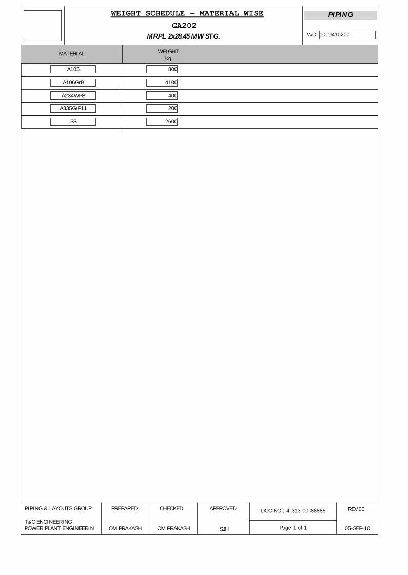
GA202MRPL 2x28.45 MW STG.
MATERIAL WEIGHTKg
WEIGHT SCHEDULE - MATERIAL WISE
DOC NO : 4-313-00-88885PIPING & LAYOUTS GROUP
T&C ENGINEERINGPOWER PLANT ENGINEERIN
PREPARED CHECKED APPROVED
OM PRAKASH OM PRAKASH SJH
REV
05-SEP-10
00
1019410200WO:
PIPING
Page 1 of 1
A105
A106GrB
A234WPB
A335GrP11
SS
800
4100
400
200
2600

SPECIFICATION NO.
A011-06-42-PT-G09, Rev.0
JOB SPECIFICATION FOR SHOP & FIELD PAINTING,
SMMS DEPARTMENT CAPATIVE POWER PLANT
PARADIP REFINERY PROJECT, IOCL Page 1 of 60
0 28-07-2009 ISSUED AS JOB SPECIFICATION BY SMMS DEPARTMENT AS DR.DNW
RC
Rev. No Date Purpose Prepared
by Checked
by Approved by
Format No. 8-00-0001-F1 Rev. 0 Copyright EIL – All rights reserved
JOB SPECIFICATION FOR SHOP & FIELD PAINTING
SMMS DEPARTMENT
CAPTIVE POWER PLANT
PROJECT : PARADIP REFINERY
OWNER : INDIAN OIL CORPORATION LIMITED (IOCL) PMC : ENGINEERS INDIA LTD. JOB NO. : A011

SPECIFICATION NO.
A011-06-42-PT-G09, Rev.0 JOB SPECIFICATION FOR
SHOP & FIELD PAINTING, SMMS DEPARTMENT
CAPATIVE POWER PLANT PARADIP REFINERY PROJECT, ICOL Page 2 of 60
Format No. 8-00-0001-F1 Rev. 0 Copyright EIL – All rights reserved
Abbreviations: AS : Alloy Steel CS : Carbon Steel LTCS : Low Temperature Carbon Steel MS : Mild Steel SS : Stainless Steel GI : Galvanized Iron DFT : Dry Film Thickness WFT : Wet Film Thickness DM : De-mineralized ID : Internal Diameter OD : Outside Diameter NB : Nominal Bore RCC : Reinforced Cement Concrete IRN : Inspection Release Note

SPECIFICATION NO.
A011-06-42-PT-G09, Rev.0 JOB SPECIFICATION FOR
SHOP & FIELD PAINTING, SMMS DEPARTMENT
CAPATIVE POWER PLANT PARADIP REFINERY PROJECT, ICOL Page 3 of 60
Format No. 8-00-0001-F1 Rev. 0 Copyright EIL – All rights reserved
CONTENTS
SL. NO DESCRIPTION PAGE
NO. 1.0 General 4 2.0 Scope 4 3.0 Reference Codes & Standards 6 4.0 Equipment 6 5.0 Surface Preparation, Shop Primer, Coating Application & Repair and
Documentation 7
6.0 Paint Materials 16 7.0 Paint Systems 21 8.0 Paint System for Corrosive Environment-Offsite Areas (Excluding Cooling
Tower Area & DM Plant Area) 24
9.0 Paint System for Corrosive Environment-Unit Areas 25 10.0 Paint System for Highly Corrosive Environment-Unit & Offsite Areas of the
Plant with Corrosive Fumes like HCL, H2SO4, Water Impingement, Salty Water, Chloride & Water Mist, DM Plant Area, Cooling Tower Area
26
11.0 Paint System for Carbon Steel and Low Alloy Steel Storage Tanks (External)- All Areas (Units & Offsites)
27
12.0 Paint System for Carbon Steel and Low Alloy Steel Storage Tanks (Internal); All Areas (Units & Offsites)
28
13.0 Coating System for External Side of Underground Carbon Steel Plant Piping and Underground Tanks in All Areas
30
14.0 Painting Under Insulation All Environments/All Areas (Units & Offsites) 31 15.0 Internal Protection of Carbon Steel Coolers/ Condensers. 32 16.0 Field Painting System for GI Towers/Non-Ferrous Tube Sheet 32 17.0 Shop and Field Painting system for ETP 33 18.0 Storage 34 19.0 Colour Code for Piping 34 20.0 Identification of Vessels, Piping etc. 43 21.0 Painting for Civil Defence Requirements 43 22.0 Inspection and Testing 43 23.0 Guarantee 45 24.0 Qualification Criteria of Painting Contractor 45 25.0 Procedure for Approval of New Paint Manufacturers 45
Annexure-I – List of Recommended Manufacturers 47 Annexure-II – List of Recommended Manufacturers’ Products 48

SPECIFICATION NO.
A011-06-42-PT-G09, Rev.0 JOB SPECIFICATION FOR
SHOP & FIELD PAINTING, SMMS DEPARTMENT
CAPATIVE POWER PLANT PARADIP REFINERY PROJECT, ICOL Page 4 of 60
Format No. 8-00-0001-F1 Rev. 0 Copyright EIL – All rights reserved
1.0 GENERAL 1.1 These technical specifications shall be applicable for the work covered by the contract,
and without prejudice to the provisions of various codes of practice, standard specifications etc. It is understood that contractor shall carry out the work in all respects with the best quality of materials and workmanship and in accordance with the best engineering practice and instructions of Engineer-In-Charge.
1.2 Wherever it is stated in the specification that a specific material is to be supplied or a
specific work is to be done, it shall be deemed that the same shall be supplied or carried out by the contractor.
Any deviation from this standard without written deviation permit from appropriate
authority will result in rejection of job. 2.0 SCOPE 2.1 Scope of work covered in the specification shall include, without being limited to the
following. 2.1.1 This specification defines the requirements for surface preparation, selection and
application of primers and paints on external surfaces of equipment, vessels, machinery, piping, ducts, steel structures, external & internal protection of storage tanks for all services, MS Chimney with & without Refractory lining, MS Chimney with insulation and without insulation and Flare lines etc. The items listed in the heading of tables of paint systems is indicative only, however, the contractor is fully responsible for carrying out all the necessary painting, coating and lining on external and internal surfaces as per the tender requirement.
2.2 Extent of Work 2.2.1 The following surfaces and materials shall require shop, pre-erection and field painting:
a. All uninsulated C.S. & A.S. equipment like columns, vessels, drums, storage tanks(both external & internal surfaces), heat exchangers, pumps, compressors, electrical panels and motors etc.
b. All uninsulated carbon and low alloy piping, fittings and valves (including
painting of identification marks), furnace ducts and stacks. c. All items contained in a package unit as necessary. d. All structural steel work, pipe, structural steel supports, walkways, handrails,
ladders, platforms etc. e. Flare lines, external surfaces of MS chimney with and without refractory lining
and internal surfaces of MS chimney without refractory lining. MS chimney with insulation and without un-insulation.
f. Identification colour bands on all piping as required including insulated
aluminium clad, galvanised, SS and nonferrous piping.

SPECIFICATION NO.
A011-06-42-PT-G09, Rev.0 JOB SPECIFICATION FOR
SHOP & FIELD PAINTING, SMMS DEPARTMENT
CAPATIVE POWER PLANT PARADIP REFINERY PROJECT, ICOL Page 5 of 60
Format No. 8-00-0001-F1 Rev. 0 Copyright EIL – All rights reserved
g. Identification lettering/ numbering on all painted surfaces of equipment/piping insulated aluminium clad, galvanized, SS and non-ferrous piping
h. Marking / identification signs on painted surfaces of equipment/piping including
hazardous service. i. Supply of all primers, paints and all other materials required for painting (other
than Owner supplied materials) j. Over insulation surface of equipments and pipes wherever required. k. Painting under insulation for carbon steel, alloy steel and stainless steel as
specified.
l. Painting of pre-erection/fabrication and Shop primer.
m. Repair work of damaged pre-erection/ fabrication and shop primer and weld joints in the field/site before and after erection as required.
n. All CS Piping, equipments, storage tanks and internal surfaces of RCC tanks in
ETP plant. 2.2.2 The following surfaces and materials shall not require painting in general. However, if
there is any specific requirement by the owner, the same shall be painted as per the relevant specifications:
a. Uninsulated austenitic stainless steel. b. Plastic and/or plastic coated materials c. Non-ferrous materials like aluminum.
2.3 Documents 2.3.1 The contractor shall perform the work in accordance with the following documents
issued to him for execution of work. a. Bill of quantities for piping, equipment, machinery and structures etc. b. Piping Line List. c. Painting specifications including special civil defence requirements. 2.4 Unless otherwise instructed, final painting on pre-erection/ shop primed pipes and
equipments shall be painted in the field, only after the mechanical completion, testing on systems are completed as well as after completion of steam purging wherever required.
2.5 Changes and deviations required for any specific job due to clients requirement or
otherwise shall be referred to EIL for deviation permit.

SPECIFICATION NO.
A011-06-42-PT-G09, Rev.0 JOB SPECIFICATION FOR
SHOP & FIELD PAINTING, SMMS DEPARTMENT
CAPATIVE POWER PLANT PARADIP REFINERY PROJECT, ICOL Page 6 of 60
Format No. 8-00-0001-F1 Rev. 0 Copyright EIL – All rights reserved
3.0 REFERENCE CODES & STANDARDS 3.1 Without prejudice to the provision of Clause 1.1 above and the detailed specifications of
the contract, latest editions of the following codes and standards are applicable for the work covered by this contract.
IS-5 : Colour coding. RAL DUTCH : International Standard for colour shade (Dutch Standard)
IS-101 : Methods of test for ready mixed paints and enamels. IS-2379 : Indian Standard for Pipe line identification-colour code. ASTM-Vol 6.01 & 6.03: American standard test methods for Paints and Coatings.
ASA A 13.1-1981: Scheme for identification of piping systems: American National Standards Institution.
3.2 Surface Preparation Standards The latest editions of any of the following standards shall be followed for surface
preparation: 3.2.1 ISO 8501-1 / SIS-05 59 00: ISO standard for Preparation of steel substrates before
application of paints and related products. This standard contains photographs of the various standards on four different degrees of rusted steel and as such is preferable for inspection purpose by the Engineer-In-Charge.
3.2.2 Steel Structures Painting Council, U.S.A. (Surface Preparation Specifications (SSPC-
SP). 3.2.3 National Association of Corrosion Engineers, U.S.A., (NACE). 3.2.4 Various International Standards equivalent to Swedish Standard for surface
preparations are given in Table-I. 3.3 The contractor shall arrange, at his own cost, to keep a set of latest edition of above
standards and codes at site. 3.4 The paint manufacturer's instructions shall be followed as far as practicable at all times
for best results. Particular attention shall be paid to the following: a. Instructions for storage to avoid exposure as well as extremes of temperature.
b. Surface preparation prior to painting shall be followed as per Table 8.0 to 16.0 of this standard shall be followed.
c. Mixing and thinning. d. Application of paints and recommended limit on time intervals in between
coats. 4.0 EQUIPMENT 4.1 All tools, brushes, rollers, spray guns, blast material, hand power tools for cleaning and
all equipments, scaffolding materials, shot & grit blasting equipments & air compressors etc. required to be used shall be suitable for the work and all in good order and shall be

SPECIFICATION NO.
A011-06-42-PT-G09, Rev.0 JOB SPECIFICATION FOR
SHOP & FIELD PAINTING, SMMS DEPARTMENT
CAPATIVE POWER PLANT PARADIP REFINERY PROJECT, ICOL Page 7 of 60
Format No. 8-00-0001-F1 Rev. 0 Copyright EIL – All rights reserved
arranged by the contractor at site and in sufficient quantity. The manufacturer’s test certificates / data sheets for all the above items shall be reviewed by Engineer-in-charge at site before start of work.
4.2 Mechanical mixer shall be used for paint mixing operations in case of two pack systems
except that the Engineer-In-Charge may allow the hand mixing of small quantities at his discretion in case of specific requirement for touch up work only.
5.0 SURFACE PREPARATION, SHOP PRIMER COATING APPLICATION & REPAIR
AND DOCUMENTATION 5.1 General 5.1.1 In order to achieve the maximum durability, one or more of following methods of
surface preparation shall be followed, depending on condition of surface to be painted and as instructed by Engineer-In-Charge. Adhesion of the paint film to surface depends largely on the degree of cleanliness of the metal surface. Proper surface preparation contributes more to the success of the paint protective system.
a. Manual or hand tool cleaning. b. Mechanical or power tool cleaning.
c. Blast cleaning. 5.1.2 Mill scale, rust, rust scale and foreign matter shall be removed fully to ensure that a
clean and dry surface is obtained. Unless otherwise specified, surface preparation shall be done as per provisions of relevant tables given elsewhere in this specification The minimum acceptable standard in case of manual or hand tool cleaning shall be St. 2 or equivalent, in case of mechanical or power tool cleaning it shall be St. 3 or equivalent, in case of blast cleaning it shall be Sa 2-1/2 as per Swedish Standard SIS-055900(latest edition) or SSPC-SP or ISO 8501-01.Blast cleaning shall be Sa 3 as per Swedish Standard in case of highly corrosive environment.
Remove all other contaminants, oil, grease etc. by use of an aromatic solvent prior to
surface cleaning. 5.1.3 Blast cleaning shall not be performed where dust can contaminate surfaces undergoing
such cleaning or during humid weather conditions having humidity exceed 85%. Incase of internal coating of storage tanks, De-humidifiers shall be used to control the humidity levels during rainy season, if painting is to be carried out during the no rain days in case of exigency of project schedule with prior permission of Engineer-in-charge of OWNER/EIL
5.1.4 Irrespective of the method of surface preparation, the first coat of primer must be
applied by airless spray/ air assisted conventional spray if recommended by the paint manufacturer on dry surface. This should be done immediately and in any case within 4 hours of cleaning of surface. However, at times of unfavorable weather conditions, the Engineer-In-Charge shall have the liberty to control the time period, at his sole discretion and/or to insist on re-cleaning, as may be required, before primer application is taken up. In general, during unfavorable weather conditions, blasting and painting shall be avoided as far as practicable.

SPECIFICATION NO.
A011-06-42-PT-G09, Rev.0 JOB SPECIFICATION FOR
SHOP & FIELD PAINTING, SMMS DEPARTMENT
CAPATIVE POWER PLANT PARADIP REFINERY PROJECT, ICOL Page 8 of 60
Format No. 8-00-0001-F1 Rev. 0 Copyright EIL – All rights reserved
5.1.5 The external surface of R.C.C. chimney to be painted shall be dry and clean. Any loose particle of sand, cement, aggregate etc. shall be removed by scrubbing with soft wire brush. Acid etching with 10-15% HCL solution for about 15 minutes shall be carried and surface must be thoroughly washed with water to remove acid & loose particles and then dried completely before application of paint.
5.2 Procedure of Surface Preparation : 5.2.1 Air Blast Cleaning with abrasives
The surfaces shall be blast cleaned using one of the abrasives like copper slag, A12O3 particles, chilled cast iron or malleable iron and steel at pressure of 7kg/cm2 at a appropriate distance and angle depending of nozzle size maintaining constant velocity and pressure. Chilled cast iron, malleable iron and steel shall be in the form of shot or grit of size with appropriate size of G42 grade (maximum) and S250 grade size of steel shots (maximum) to obtain a desired surface profile of 35-50 microns trough to peak or specified profile in case of steel and malleable iron . The combination of steel grits and shots shall be normally in the ratio of 3 : 1. The quality of abrasives shall be free from contaminants and impurities and shall meet the requirements of SSPC AB1. Compressed air shall be free from moisture and oil. The blasting nozzles should be venturi style with tungsten carbide or boron carbide as the materials for liners. Nozzles orifice may vary from 3/16” to ¾”. On completion of blasting operation, the blasted surface shall be clean and free from any scale or rust and must show a grey white metallic luster. Primer/first coat of paint shall be applied within 4 hours of surface preparation. Blast cleaning shall not be done outdoors in bad weather without adequate protection or when there is dew on the metal, which is to be cleaned. Surface profile shall be uniform to provide good key to the paint adhesion (i.e. 35 to 50 microns ). If possible vacuum collector shall be installed for collecting the abrasives and recycling.
5.2.2 Mechanical or Power Tool Cleaning Power tool cleaning shall be done by mechanical striking tools, chipping hammers,
grinding wheels or rotating steel wire- brushes. Excessive burnish of surface shall be avoided as it can reduce paint adhesion. On completion of cleaning, the detached rust mill scale etc. shall be removed by clean rags and /or washed by water or steam and thoroughly dried with compressed air jet before application of paint.
5.2.3 Manual or hand tool cleaning Manual or hand tool cleaning is used only where safety problems limit the application of
other surface preparation procedure and hence does not appear in the tables of paint systems.
Hand tool cleaning normally consists of the following:
a. Hand de-scaling and/or hammering
b. Hand scraping
c. Hand wire brushing Rust, mill scale spatters, old coatings and other foreign matter, shall be removed by
hammering, scrapping tools, emery paper cleaning, wire brushing or combination of the
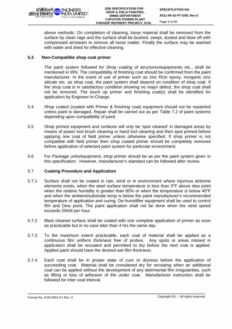
SPECIFICATION NO.
A011-06-42-PT-G09, Rev.0 JOB SPECIFICATION FOR
SHOP & FIELD PAINTING, SMMS DEPARTMENT
CAPATIVE POWER PLANT PARADIP REFINERY PROJECT, ICOL Page 9 of 60
Format No. 8-00-0001-F1 Rev. 0 Copyright EIL – All rights reserved
above methods. On completion of cleaning, loose material shall be removed from the surface by clean rags and the surface shall be bushed, swept, dusted and blow off with compressed air/steam to remove all loose matter. Finally the surface may be washed with water and dried for effective cleaning.
5.3 Non-Compatible shop coat primer The paint system followed for Shop coating of structures/equipments etc., shall be
mentioned in IRN. The compatibility of finishing coat should be confirmed from the paint manufacturer. In the event of use of primer such as zinc Rich epoxy, inorganic zinc silicate etc. as shop coat, the paint system shall depend on condition of shop coat. If the shop coat is in satisfactory condition showing no major defect, the shop coat shall not be removed. The touch up primer and finishing coat(s) shall be identified for application by Engineer-in-Charge.
5.4 Shop coated (coated with Primer & finishing coat) equipment should not be repainted
unless paint is damaged. Repair shall be carried out as per Table 7.2 of paint systems depending upon compatibility of paint.
5.5 Shop primed equipment and surfaces will only be 'spot cleaned' in damaged areas by
means of power tool brush cleaning or hand tool cleaning and then spot primed before applying one coat of field primer unless otherwise specified. If shop primer is not compatible with field primer then shop coated primer should be completely removed before application of selected paint system for particular environment.
5.6 For Package units/equipment, shop primer should be as per the paint system given in
this specification. However, manufacturer’s standard can be followed after review. 5.7 Coating Procedure and Application 5.7.1 Surface shall not be coated in rain, wind or in environment where injurious airborne
elements exists, when the steel surface temperature is less than 5oF above dew point when the relative humidity is greater than 85% or when the temperature is below 40oF and when the ambient/substrate temp is below the paint manufacturer’s recommended temperature of application and curing. De-humidifier equipment shall be used to control RH and Dew point. The paint application shall not be done when the wind speed exceeds 20KM per hour.
5.7.2 Blast cleaned surface shall be coated with one complete application of primer as soon
as practicable but in no case later than 4 hrs the same day. 5.7.3 To the maximum extent practicable, each coat of material shall be applied as a
continuous film uniform thickness free of probes. Any spots or areas missed in application shall be recoated and permitted to dry before the next coat is applied. Applied paint should have the desired wet film thickness.
5.7.4 Each coat shall be in proper state of cure or dryness before the application of
succeeding coat. Material shall be considered dry for recoating when an additional coat can be applied without the development of any detrimental film irregularities, such as lifting or loss of adhesion of the under coat. Manufacturer instruction shall be followed for inter coat interval.

SPECIFICATION NO.
A011-06-42-PT-G09, Rev.0 JOB SPECIFICATION FOR
SHOP & FIELD PAINTING, SMMS DEPARTMENT
CAPATIVE POWER PLANT PARADIP REFINERY PROJECT, ICOL Page 10 of 60
Format No. 8-00-0001-F1 Rev. 0 Copyright EIL – All rights reserved
5.7.5 When the successive coat of the same colour have been specified, alternate coat shall be tinted, when practical, sufficiently to produce enough contrast to indicate complete coverage of the surface. The tinting material shall be compatible with the material and not detrimental to its service life and shall be recommended by the original paint manufacturer.
5.7.6 Air spray application shall be in accordance with the following:
a. The equipment used shall be suitable for the intended purpose, shall be capable of properly atomizing the paint to be applied, and shall be equipped with suitable pressure regulators and gauges. The air caps, nozzles, and needles shall be those recommended by the manufacturer of the equipment for the material being sprayed. The equipment shall be kept in satisfactory condition to permit proper paint application.
b. Traps or separators shall be provided to remove oil and condensed water from
the air. These traps or separators must be of adequate size and must be drained periodically during operations. The air from the spray gun impinging against the surface shall show no condensed water or oil.
c. Ingredients shall be kept properly mixed in the spray pots or containers
during application by continuous mechanical agitation.
d. The pressure on the material in the pot and of the air at the gun shall be adjusted for optimum spraying effectiveness. The pressure on the material in the pot shall be adjusted when necessary for changes in elevation of the gun above the pot. The atomizing air pressure at the gun shall be high enough to properly atomize the paint but not so high as to cause excessive fogging of paint, excessive evaporation of solvent, or less by over spray
e. Spray equipment shall be kept sufficiently clean so that dirt, dried paint, and
other foreign materials are not deposited in the paint film.
Any solvents left in the equipment shall be completely removed before applying paint to the surface being painted.
f. Paint shall be applied in a uniform layer, with overlapping at the edge of the
spray pattern. The spray patterns shall be adjusted so that the paint is deposited uniformly. During application, the gun shall be held perpendicular to the surface and at a distance which will ensure that a wet layer of paint is deposited on the surface. The trigger of the gun should be released at the end of each stroke.
g. All runs and sags shall be brushed out immediately or the paint shall be
removed and the surface repainted.
h. Areas inaccessible to the spray gun shall be painted by brush; if not accessible by brush, daubers or sheepskins shall be used.
i. All nameplates, manufacturer’s identification tags, machined surfaces,
instrument glass, finished flange faces, control valve items and similar items shall be masked to prohibit coating deposition. If these surfaces are coated, the component shall be cleaned and resorted to its original condition.

SPECIFICATION NO.
A011-06-42-PT-G09, Rev.0 JOB SPECIFICATION FOR
SHOP & FIELD PAINTING, SMMS DEPARTMENT
CAPATIVE POWER PLANT PARADIP REFINERY PROJECT, ICOL Page 11 of 60
Format No. 8-00-0001-F1 Rev. 0 Copyright EIL – All rights reserved
j. Edges of structural shapes and irregular coated surfaces shall be coated first
and an extra pass made later.
k. If spray gun shows choking, immediately de-choking procedure shall be followed.
5.7.7 Airless spray application shall be in accordance with the following procedure: as per
stesl structure paint Manual Vol.1 & Vol.2 by SSPC, USA, Air less spray relies on hydraulic pressure rather than air atomization to produce the desired spray. An air compressor or electric motor is used to operate a pump to produce pressures of 1000 to 6000 psi. paint is delivered to the spray gun at this pressure through a single hose within the gun, a single paint stream is divided into separate streams, which are forced through a small orifice resulting in automization of paint without the use of air. This results in more rapid coverage with less over spray. Airless spray usually is faster, cleaner, more economical and easier to use than conventional air spray.
Airless spray equipment is mounted on wheels, and paint is aspirated in a hose that sucks paint from any container, including drums. The unit shall have in built agitator that keep the paint uniformly mixed during the spraying. The unit shall consist of in built strainer. Usually very small quantity of thinning is required before spray. In case of high build epoxy coating (two pack). 30:1 pump ratio and 0.020-0.023” tip size will provide a good spray pattern. Ideally fluid hoses should not be less than 3/8” ID and not longer than 50 ft to obtain optimum results.
In case of gun choking, de-choking steps shall be followed immediately.
5.7.8 Brush application of paint shall be in accordance with the following:
a. Brushes shall be of a style and quality that will enable proper application of paint.
b. Round or oval brushes are most suitable for rivets, bolts, irregular surface, and
rough or pitted steel. Wide flat brushes are suitable for large flat areas, but they shall not have width over five inches.
c. Paint shall be applied into all corners. d. Any runs or sags shall be brushed out. e. There shall be a minimum of brush marks left in the applied paint. f. Surfaces not accessible to brushes shall be painted by spray, doubers, or
sheepkin. 5.7.9 Manual application by sling (where 6 O’ clock position of pipe is not approachable)
A canvas strip (alternatively a tinplate strip) about 450 mm wide and 1.5m long is hold under the pipe by two men holding this sling move it up and down and walk slowly forward while fresh coating is poured on the pipe and they manipulate the sling so that an even coating is obtained all round the bottom. This work shall be done very carefully and by experienced personnel. There shall not be any formation of “Whiskers” and holes in the coating. The coating film shall be inspected by mirror.

SPECIFICATION NO.
A011-06-42-PT-G09, Rev.0 JOB SPECIFICATION FOR
SHOP & FIELD PAINTING, SMMS DEPARTMENT
CAPATIVE POWER PLANT PARADIP REFINERY PROJECT, ICOL Page 12 of 60
Format No. 8-00-0001-F1 Rev. 0 Copyright EIL – All rights reserved
5.7.10 For each coat the painter should know the WFT corresponding to the specified DFT
and standardize the paint application technique to achieve the desired WFT. This has to be ensured in the qualification trial.
5.8 Drying of coated surfaces 5.8.1 No coat shall be applied until the preceding coat has dried. The material shall be
considered dry for re-coating when another coat can be applied without the development of any film irregularities such as lifting or loss of adhesion of undercoats. Drying time of the applied coat should not exceed maximum specified for it as a first coat; if it exceeds the paint material has possibly deteriorated or mixing is faulty.
5.8.2 No paint shall be force dried under conditions which will cause checking, wrinkling,
blistering formation of pores, or detrimentally affect the conditions of the paint. 5.8.3 No drier shall be added to a paint on the job unless specifically called for in the
manufacturer’s specification for the paint. 5.8.4 Paint shall be protected from rain, condensation, contamination, snow and freezing until
dry to the fullest extent practicable. 5.9 Repair of damaged paint surface 5.9.1 Where paint has been damaged in handling and in transportation, the repair of
damaged coating of pre-erection / fabrication and Shop primer shall be done as given below and as per the Table 7.2 of this specification.
5.9.2 Repair of damaged inorganic zinc silicate primer after erection / welding in the design
temperature of -90oC to 550oC.
Surface Preparation: Quickly remove the primer from damaged area by mechanical scraping and emery paper conforming to SSPC-SP-3 to expose the white metal. Blast clean the surface, if possible. Feather the primed surface over the intact adjacent surface surrounding the damaged area by emery paper.
Primer coating: One coat of F-9 shall be applied wherever damaged was observed on pre-erection pre fabrication / shop primer of inorganic zinc silicate coating (F-9). F-9 shall not be applied if damaged area is not more than 5x5 cm.
5.10 Paint Application 5.10.1 Shop priming/pre-erection priming with F9 or F12 shall be done only on blasted surface
(SSPC-SP-10) 5.10.2 Shop priming/ pre-erection priming with F9 or F12 shall be done only with airless spray. 5.10.3 For large flat surface field painting shall be done by airless spray otherwise brush can
be used. 5.10.4 Assessment of painting requirement

SPECIFICATION NO.
A011-06-42-PT-G09, Rev.0 JOB SPECIFICATION FOR
SHOP & FIELD PAINTING, SMMS DEPARTMENT
CAPATIVE POWER PLANT PARADIP REFINERY PROJECT, ICOL Page 13 of 60
Format No. 8-00-0001-F1 Rev. 0 Copyright EIL – All rights reserved
The paint system to be applied for a specific job shall be arrived at sequentially as given below:
- Identify the environment from area classification details and chose the appropriate
table. - Identify the design temperature from the technical documents - Identify the specific field paint system and surface preparation requirement from the
above identified table and temperature range. - Identify the shop priming requirement from Table 7.1 based on compatibility of the
above paint system. - Identify the need of repair of shop primer and execute as per Table 7.2.
5.11 Documentation 5.11.1 A written quality plan with procedure for qualification trials and for the actual work. 5.11.2 Daily progress report with details of weather conditions, particular of applications, no of
coats and type of materials applied, anomalies, progress of work versus program. 5.11.3 Results of measurement of temperatures relative humidity, surface profile, film
thickness, holiday detection, adhesion tests with signature of appropriate authority. 5.11.4 Particulars of surface preparation and paint application during trials and during the
work. 5.11.5 Details of non-compliance, rejects and repairs. 5.11.6 Type of testing equipments and calibration. 5.11.7 Code and batch numbers of paint materials used.
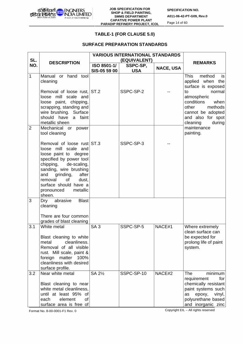
SPECIFICATION NO.
A011-06-42-PT-G09, Rev.0 JOB SPECIFICATION FOR
SHOP & FIELD PAINTING, SMMS DEPARTMENT
CAPATIVE POWER PLANT PARADIP REFINERY PROJECT, ICOL Page 14 of 60
Format No. 8-00-0001-F1 Rev. 0 Copyright EIL – All rights reserved
TABLE-1 (FOR CLAUSE 5.0)
SURFACE PREPARATION STANDARDS
VARIOUS INTERNATIONAL STANDARDS (EQUIVALENT) SL.
NO. DESCRIPTION ISO 8501-1/ SIS-05 59 00
SSPC-SP, USA NACE, USA
REMARKS
1 Manual or hand tool cleaning Removal of loose rust, loose mill scale and loose paint, chipping, scrapping, standing and wire brushing. Surface should have a faint metallic sheen
ST.2
SSPC-SP-2
--
2 Mechanical or power tool cleaning Removal of loose rust loose mill scale and loose paint to degree specified by power tool chipping, de-scaling, sanding, wire brushing and grinding, after removal of dust, surface should have a pronounced metallic sheen.
ST.3
SSPC-SP-3
--
This method is applied when the surface is exposed to normal atmospheric conditions when other methods cannot be adopted and also for spot cleaning during maintenance painting.
3 Dry abrasive Blast cleaning There are four common grades of blast cleaning
3.1 White metal Blast cleaning to white metal cleanliness. Removal of all visible rust. Mill scale, paint & foreign matter 100% cleanliness with desired surface profile.
SA 3 SSPC-SP-5 NACE#1 Where extremely clean surface can be expected for prolong life of paint system.
3.2 Near white metal Blast cleaning to near white metal cleanliness, until at least 95% of each element of surface area is free of
SA 2½ SSPC-SP-10 NACE#2 The minimum requirement for chemically resistant paint systems such as epoxy, vinyl, polyurethane based and inorganic zinc

SPECIFICATION NO.
A011-06-42-PT-G09, Rev.0 JOB SPECIFICATION FOR
SHOP & FIELD PAINTING, SMMS DEPARTMENT
CAPATIVE POWER PLANT PARADIP REFINERY PROJECT, ICOL Page 15 of 60
Format No. 8-00-0001-F1 Rev. 0 Copyright EIL – All rights reserved
VARIOUS INTERNATIONAL STANDARDS (EQUIVALENT) SL.
NO. DESCRIPTION ISO 8501-1/ SIS-05 59 00
SSPC-SP, USA NACE, USA
REMARKS
all visible residues with desired surface profile.
silicate paints, also for conventional paint systems used under fairly corrosive conditions to obtain desired life of paint system.
3.3 Commercial Blast Blast cleaning until at least two-third of each element of surface area is free of all visible residues with desired surface profile.
SA 2 SSPC-SP-6 NACE # 3 For steel required to be painted with conventional paints for exposure to mildly corrosive atmosphere for longer life of the paint systems.
3.4 Brush-off Blast Blast cleaning to white metal cleanliness, removal of all visible rust, mill scale, paint & foreign matter. Surface profile is not so important
SA 1 SSPC-SP-7 NACE # 4

SPECIFICATION NO.
A011-06-42-PT-G09, Rev.0 JOB SPECIFICATION FOR
SHOP & FIELD PAINTING, SMMS DEPARTMENT
CAPATIVE POWER PLANT PARADIP REFINERY PROJECT, ICOL Page 16 of 60
Format No. 8-00-0001-F1 Rev. 0 Copyright EIL – All rights reserved
6.0 PAINT MATERIALS Paint manufacturers shall furnish the characteristics of all paints materials on original
printed literature, alongwith the test certificate for all specified characteristics given in this specification. All the paint materials shall be of first quality and conform to the following general characteristics as per the tables 6.1, 6.2, 6.3 and 6.4.
PAINT MATERIALS TABLE No. 6.1 PRIMERS
Sl. No.
DESCRIPTION P-2 P-4 P-6 P-7
1 Technical name Chlorinated rubber Zinc Phosphate primer.
Etch primer/wash primer
Epoxy zinc phosphate primer
ZINGA synthetic zinc primer
2 Type and composition
Single pack, air drying chlorinated rubber based medium plasticised with unsaponifiable plasticizer, pigmented with zinc phosphate.
Two pack polyvinyl butyral resin medium cured with phosphoric acid solution pigmented with zinc tetroxy chromate.
Two component polyamine cured epoxy resin medium, pigmented with zinc phosphate.
One pack Synthetic Resin based zinc primer containing 96% of electrolytic zinc dust of 99.995% purity.
3 Volume Solids (minimum)
40%. 7-8% 40% 37%
4 DFT (Dry Film thickness) per coat (minimum)
30-40µ 8-10µ 40-50µ 40-50µ
5 Theoritical covering capacity in M2/coat/ litre (minimum)
8-10 8-10 8-10 4m²/kg
6 Weight per litre in kgs/litre (minimum)
1.3 1.2 1.4 2.67 kg at 15oC
7 Touch dry at 30oC (minimum)
30 minutes 2 hrs. After 30 min. 10 minutes
8 Hard dry at 30oC (maximum.)
24 hrs. 24 hrs. 24 hrs. 24 hrs.
9 Overcoating interval Min.: 8 hrs
Min: 4-6 hrs.
Min.:8hrs. Min.:4 hrs
10 Pot life at 30oC for two component paints (minimum)
Not Applicable
Not applicable 6 - 8 hrs. Unlimited
11 Temperature (Resistance (minimum)
60 oC NA 80oC 100oC.

SPECIFICATION NO.
A011-06-42-PT-G09, Rev.0 JOB SPECIFICATION FOR
SHOP & FIELD PAINTING, SMMS DEPARTMENT
CAPATIVE POWER PLANT PARADIP REFINERY PROJECT, ICOL Page 17 of 60
Format No. 8-00-0001-F1 Rev. 0 Copyright EIL – All rights reserved
PAINT MATERIALS
TABLE No. 6.2 FINISH PAINTS
Sl.No DESCRIPTION F-2 F-3 F-6A/B F-7
1 Technical name Acrylic Polyurethane finish paint
Chlorinated rubber based finish paint
Epoxy-High Build finish paint.
High build coaltar epoxy coating.
2 Type and composition Two-pack aliphatic isocynate cured acrylic finish paint.
Single pack plasticised chlorinated rubber based medium with chemical and weather resistant pigments.
F6A: Two-pack polyamine cured epoxy resin medium suitably pigmented. F6B: polyamide cured epoxy resin medium suitably pigmented
Two pack polyamide cured epoxy resin blended with coaltar medium, suitably pigmented
3 Volume Solids (minimum.)
40%. 40% 62% 65%
4 DFT (Dry Film thickness) per coat (minimum)
30-40µ 30-40µ 100-125µ 100-125µ
5 Theoritical covering capacity in M2/coat/litre (minimum)
10-13 8-10 5-6 5.2-6.5
6 Weight per liter in kgs/litre(minimum)
1.3 1.2 1.4 1.5
7 Touch dry at 30oC 1 hr. 30 minutes. 3 hrs. 4 hrs. 8 Hard dry at 30oC
(max) Full cure at 30oC (for immersion/ high temperature service)
16 hrs 5 days
8 hrs NA
16 hrs 5 days
48 hrs. 5 days
9 Over-coating interval at 30 oC
Min.: 12 hrs.
Min.: Overnight
Min.: Overnight Max.: 5 days
Min.: 24 hrs Max.: 5 days.
10 Pot life (approx.) at 30oC for two component paints (minimum)
6-8 hrs.
Not applicable 4-6 hrs 4-6 hrs.
11 Temperature Resistance (minimum)
80 oC 60 oC 80oC 125oC.
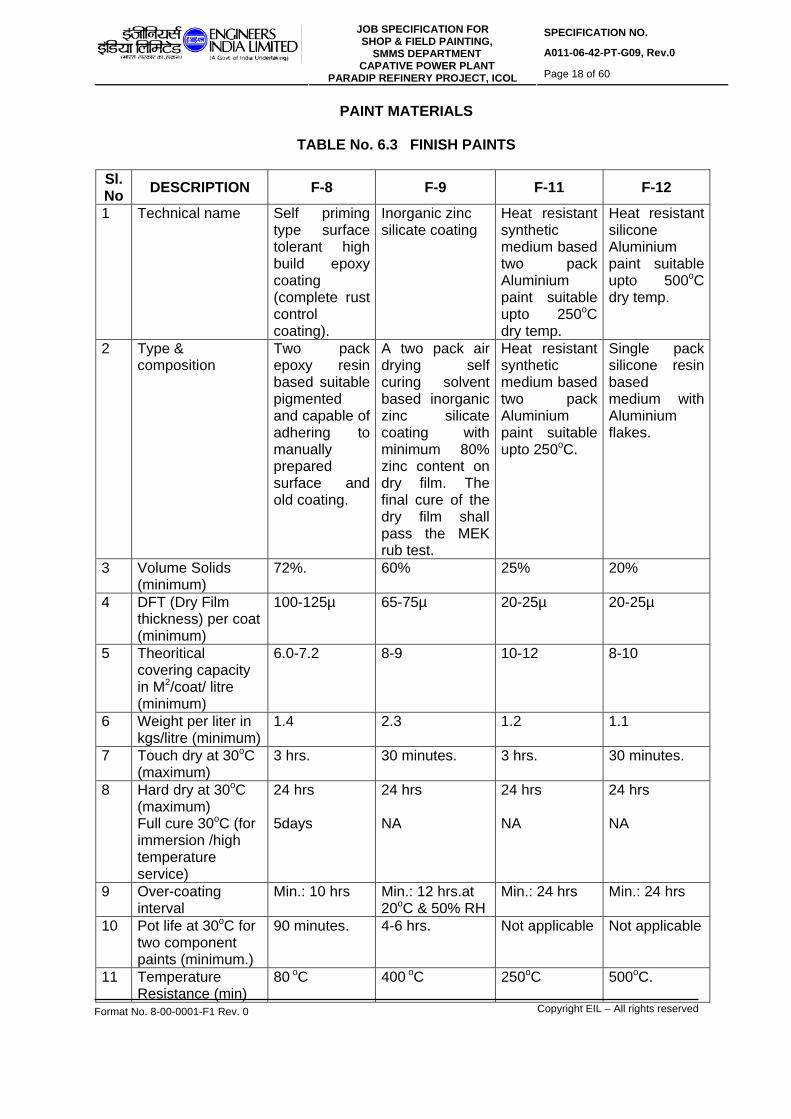
SPECIFICATION NO.
A011-06-42-PT-G09, Rev.0 JOB SPECIFICATION FOR
SHOP & FIELD PAINTING, SMMS DEPARTMENT
CAPATIVE POWER PLANT PARADIP REFINERY PROJECT, ICOL Page 18 of 60
Format No. 8-00-0001-F1 Rev. 0 Copyright EIL – All rights reserved
PAINT MATERIALS
TABLE No. 6.3 FINISH PAINTS
Sl.No DESCRIPTION F-8 F-9 F-11 F-12
1 Technical name Self priming type surface tolerant high build epoxy coating (complete rust control coating).
Inorganic zinc silicate coating
Heat resistant synthetic medium based two pack Aluminium paint suitable upto 250oC dry temp.
Heat resistant silicone Aluminium paint suitable upto 500oC dry temp.
2 Type & composition
Two pack epoxy resin based suitable pigmented and capable of adhering to manually prepared surface and old coating.
A two pack air drying self curing solvent based inorganic zinc silicate coating with minimum 80% zinc content on dry film. The final cure of the dry film shall pass the MEK rub test.
Heat resistant synthetic medium based two pack Aluminium paint suitable upto 250oC.
Single pack silicone resin based medium with Aluminium flakes.
3 Volume Solids (minimum)
72%. 60% 25% 20%
4 DFT (Dry Film thickness) per coat (minimum)
100-125µ 65-75µ 20-25µ 20-25µ
5 Theoritical covering capacity in M2/coat/ litre (minimum)
6.0-7.2 8-9 10-12 8-10
6 Weight per liter in kgs/litre (minimum)
1.4 2.3 1.2 1.1
7 Touch dry at 30oC (maximum)
3 hrs. 30 minutes. 3 hrs. 30 minutes.
8 Hard dry at 30oC (maximum) Full cure 30oC (for immersion /high temperature service)
24 hrs 5days
24 hrs NA
24 hrs NA
24 hrs NA
9 Over-coating interval
Min.: 10 hrs
Min.: 12 hrs.at 20oC & 50% RH
Min.: 24 hrs
Min.: 24 hrs
10 Pot life at 30oC for two component paints (minimum.)
90 minutes. 4-6 hrs. Not applicable Not applicable
11 Temperature Resistance (min)
80 oC 400 oC 250oC 500oC.

SPECIFICATION NO.
A011-06-42-PT-G09, Rev.0 JOB SPECIFICATION FOR
SHOP & FIELD PAINTING, SMMS DEPARTMENT
CAPATIVE POWER PLANT PARADIP REFINERY PROJECT, ICOL Page 19 of 60
Format No. 8-00-0001-F1 Rev. 0 Copyright EIL – All rights reserved
PAINT MATERIALS TABLE No. 6.4 FINISH PAINTS
Sl.No DESCRIPTION F-14 F-15 F-16 F-17
1 Technical name Polyamine cured coal tar epoxy
Two-component Epoxy phenolic coating cured with Polyamine adduct hardner system (primer + intermediate coat + finish paint)
Ambient temperature curing Poly Siloxane coating/High build cold applied inorganic copolymer based aluminium coating suitable for under insulation coating of CS and SS piping for high temperature service.
Two component solvent free type high build epoxy phenolic/novalac epoxy phenolic coating cured with Polyamine adduct hardner system
2 Type & composition
Specially formulated polyamine cured coal tar epoxy suitable for application under insulation
Two pack ambient temperature curing epoxy phenolic coating system suitable for application under insulation of CS/SS piping
Amercoat 738 from Ameron Products, USA/ Berger 938 from Berger Paints Ltd., or Intertherm 751 CSA from Akzo Nobel coating. Note: 6
Two component solvent free type high build epoxy phenolic/novalac epoxy phenolic coating cured with Polyamine adduct hardner system
3 Volume Solids (minimum)
70% 65% 60% 98-100 %
4 DFT (Dry Film thickness) per coat (minimum)
125 µm 75-100 µm 75-100 µm 125- 150 µm
5 Theoritical covering capacity in M2/coat/ litre (minimum)
5.5 6.5- 8.5 6.0- 8.0 6.5 - 8
6 Weight per liter in kgs/litre (mix paint) (minimum)
1.5
1.7 1.3 1.7
7 Touch dry at 30oC (maximum)
4 hrs 2 hrs 1 hr 2 hrs
8 Hard dry at 30oC (maximum) Full cure 30oC (for immersion /high temp. service)
24 hrs 168 hrs (7 days)
24 hrs 168 hrs (7 days)
16 hrs -
24 hrs 168 hrs (7 days)
9 Over-coating interval
Min. 6 hrs Max.5 days
Min. 36 hrs Max.21 days
Min.16 hrs Max. Not applicable
Min. 16 hrs Max.21 days

SPECIFICATION NO.
A011-06-42-PT-G09, Rev.0 JOB SPECIFICATION FOR
SHOP & FIELD PAINTING, SMMS DEPARTMENT
CAPATIVE POWER PLANT PARADIP REFINERY PROJECT, ICOL Page 20 of 60
Format No. 8-00-0001-F1 Rev. 0 Copyright EIL – All rights reserved
10 Pot life at 30oC for two component paints (minimum.)
4 hrs 1.5 hrs 1 hr 1 hr
11 Temperature Resistance (min)
-45oC to 125oC under insulation
-45oC to 150oC under insulation (Note: 5)
Up to 400 deg. C for CS & SS surfaces under insulation
-45oC to 150oC for immersion service
NOTES (for tables 6.1 to 6.4):
1. Covering capacity and DFT depends on method of application. Covering capacity specified above are theoretical. Allowing the losses during application, min specified DFT should be maintained.
2. All primers and finish coats should be cold cured and air drying unless otherwise
specified. 3. All paints shall be applied in accordance with manufacturer's instructions for
surface preparation, intervals, curing and application. The surface preparation, quality and workmanship should be ensured. In case of conflict between this specification and manufacturer’s recommendation, the same shall be clarified through SMMS.
4. Technical data sheets for all paints shall be supplied at the time of submission of
quotations.
5. F-15: Two-component Epoxy phenolic coating cured with Polyamine adduct hardner system (primer + intermediate coat + finish paint) suitable upto 225ºC (Intertherm 228 from M/s Akzo Nobel Coatings & Sealants, Bangalore). For all other companies, the temperature resistance shall be a maximum of 150ºC.
6. F-16: Ambient temperature curing epoxy poly siloxane Coating or high build cold
applied inorganic co-polymer based aluminium coating. ‘Amercoat 738’ from Ameron Products USA/Kansai Nerolac Paints Ltd. Mumbai,
suitable upto 400oC for CS surfaces and 600oC for SS surfaces. ‘Berger 938’ from Berger Paints Ltd Kolkata, suitable upto 400oC for CS & SS
surfaces. ‘Intertherm 751’ from Akzo Nobel Coatings and Sealants Pvt Ltd, Bangalore,
Inorganic co-polymer cold applied Aluminium spray coating suitable upto 400oC of CS & SS surfaces.
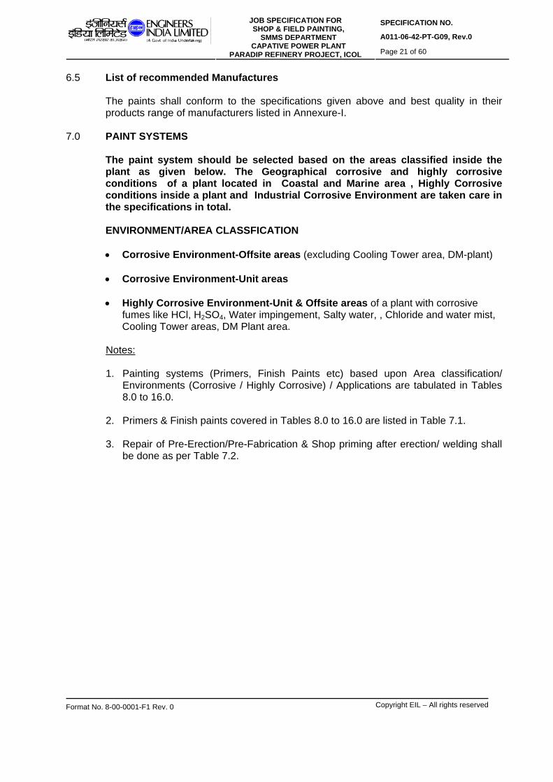
SPECIFICATION NO.
A011-06-42-PT-G09, Rev.0 JOB SPECIFICATION FOR
SHOP & FIELD PAINTING, SMMS DEPARTMENT
CAPATIVE POWER PLANT PARADIP REFINERY PROJECT, ICOL Page 21 of 60
Format No. 8-00-0001-F1 Rev. 0 Copyright EIL – All rights reserved
6.5 List of recommended Manufactures
The paints shall conform to the specifications given above and best quality in their products range of manufacturers listed in Annexure-I.
7.0 PAINT SYSTEMS The paint system should be selected based on the areas classified inside the
plant as given below. The Geographical corrosive and highly corrosive conditions of a plant located in Coastal and Marine area , Highly Corrosive conditions inside a plant and Industrial Corrosive Environment are taken care in the specifications in total.
ENVIRONMENT/AREA CLASSFICATION
• Corrosive Environment-Offsite areas (excluding Cooling Tower area, DM-plant) • Corrosive Environment-Unit areas
• Highly Corrosive Environment-Unit & Offsite areas of a plant with corrosive
fumes like HCl, H2SO4, Water impingement, Salty water, , Chloride and water mist, Cooling Tower areas, DM Plant area.
Notes: 1. Painting systems (Primers, Finish Paints etc) based upon Area classification/
Environments (Corrosive / Highly Corrosive) / Applications are tabulated in Tables 8.0 to 16.0.
2. Primers & Finish paints covered in Tables 8.0 to 16.0 are listed in Table 7.1.
3. Repair of Pre-Erection/Pre-Fabrication & Shop priming after erection/ welding shall
be done as per Table 7.2.

SPECIFICATION NO.
A011-06-42-PT-G09, Rev.0 JOB SPECIFICATION FOR
SHOP & FIELD PAINTING, SMMS DEPARTMENT
CAPATIVE POWER PLANT PARADIP REFINERY PROJECT, ICOL Page 22 of 60
Format No. 8-00-0001-F1 Rev. 0 Copyright EIL – All rights reserved
TABLE 7.1: LIST OF PRIMERS & FINISH COATS COVERED IN TABLE NOS. 8.0 - 16.0 PRIMERS
P-2 Chlorinated rubber zinc Phosphate Primer
P-4 Etch Primer/Wash Primer
P-6 Two component Epoxy Zinc Phosphate Primer cured with polyamine hardner
P-7 Single pack, synthetic resin based `ZINGA’ zinc primer containing 96% of
electrolytic zinc dust in dry film.
FINISH COATS/PAINTS
F-2 Two component Acrylic – Polyurethane finish paint
F-3 Chlorinated Rubber finish paint
F-6A High Build Epoxy finish coating cured with polyamine hardner
F-6B High Build Epoxy finish coating cured with polyamide hardner
F-7 High build Coal Tar epoxy coating cured with polyamine hardner
F-8 Self priming surface Tolerant High Build epoxy coating. cured with polyamine
hardner
F-9 Two component Inorganic Zinc Silicate coating
F-11 Heat resistant synthetic medium based Aluminium paint
F-12 Two component Heat resistant Silicone Aluminium paint.
F-14 Specially formulated coaltar epoxy coating. cured with polyamine hardner
F-15 Two component Epoxy phenolic coating cured with Polyamine adduct hardner
system
F-16 Engineered Epoxy poly Siloxane Coating or high build cold applied inorganic co-
polymer based aluminium coating
F-17 Two component solvent free type high build epoxy phenolic/novalac epoxy
phenolic coating cured with Polyamine adduct hardner system

SPECIFICATION NO.
A011-06-42-PT-G09, Rev.0 JOB SPECIFICATION FOR
SHOP & FIELD PAINTING, SMMS DEPARTMENT
CAPATIVE POWER PLANT PARADIP REFINERY PROJECT, ICOL Page 23 of 60
Format No. 8-00-0001-F1 Rev. 0 Copyright EIL – All rights reserved
TABLE 7.2 REPAIR OF PRE-ERECTION/PRE-FABRICATION & SHOP PRIMING AFTER ERECTION/WELDING for all insulated and un-insulated CS, LTCS & low allow steel items in all environments. (refer clauses 5.4, 5.5 & 5.9)
Sl. No.
Design Temp. in oC
Surface Preparation Paint System
Total DFT in Microns
(min.) Remarks
7.1 -40 to 150 for structures, hand rails and Gratings only
SSPC-SP-3
1 coat of F-9 or 2 coats of P-7 @40µ DFT/coat
65-75 (F-9) or 80 (P-7)
For few isolated damaged areas of more than 5x5 CM
7.2 -90 to 400 SSPC-SP-3
1 coat of F-9 65-75 -DO-
7.3 401 to 550
SSPC-SP-3 1 coat of F-12 20 -DO-
NOTES:
1 The application and repair of pre-erection/pre-fabrication & Shop Priming given in above tables shall be done for all the items to be painted. In case the damages of primer are severe and spread on large areas, the Engineer-in-Charge may decide to advise re-blasting and priming again if required.
2 The pre-fabrication primer P-7, ‘ZINGA’ primer is recommended as alternative repair
primer to F-9 for Structures, Hand Rails and Gratings only. F-9 shall be used for all other areas.

SPECIFICATION NO.
A011-06-42-PT-G09, Rev.0 JOB SPECIFICATION FOR
SHOP & FIELD PAINTING, SMMS DEPARTMENT
CAPATIVE POWER PLANT PARADIP REFINERY PROJECT, ICOL Page 24 of 60
Format No. 8-00-0001-F1 Rev. 0 Copyright EIL – All rights reserved
TABLE 8.0 PAINT SYSTEM FOR CORROSIVE ENVIRONMENT-OFFSITE AREAS (excluding Cooling Tower area & DM Plant area) for external surfaces of Un-insulated Structures, Piping, Equipments, Pumps, Vessels etc (Note-1); (For Carbon Steel, LTCS & Low Alloy Steel)
Paint system (Field)
Sl. No.
Design Temperatu
re in oC
Surface Preparation &
Pre-erection/Shop Primer
Primer Finish paint
Total Final DFT in
Microns (min.)
Remarks
8.1 -90 to -15 SSPC-SP-10; 1coat of F-9 @ 65-75µ DFT/coat
None None 65-75
8.2 -14 to 60 SSPC-SP-10; 1coat of F-9 @ 65-75µ DFT/coat
1 coat of P-2 @ 40µ DFT/ coat
2 coats of F-3 @ 40µ DFT/coat ; (2x40=80)
185
8.3 61 to 80 SSPC-SP-10; 1coat of F-9 @ 65-75µ DFT/coat
1 coat of P-6 @ 40µ DFT/ coat
1 coat of F-6B @ 100µ DFT/coat + 1 coat of F-2 @ 40µ DFT/coat; (100+40=140)
245
8.4 81 to 250 SSPC-SP-10; 1coat of F-9 @ 65-75µ DFT/coat
None 3 coats of F-11 @ 20µ DFT/coat; (3x20=60)
125
8.5 251 to 400 SSPC-SP-10; 1coat of F-9 @ 65-75µ DFT/coat
None 2 coats of F-12 @ 20µ DFT/coat (2x20=40) or 1 coat of F-16 @ 50 µ DFT/coat.
105-115 or 115-125
8.6 401 to 550 SSPC-SP-10; 1coat of F-12 @ 20µ DFT/coat
None 2 coats of F-12 @ 20µ DFT/coat (2x20=40)
60
No over-coating to be done on F-9 as it will lead to mud cracking. F-3 paint shall contain pure chlorinated rubber, not modified. F-12 shall be ambient temperature curing type Flare lines shall be painted as per Table 9.0.
NOTES 1 The list of items given in the heading of the above table is not exhaustive. There may be
more items for a particular contract where these specifications are used. The Contractor is fully responsible for completing painting including prefabrication primer for all the items supplied and fabricated through his scope of work as per tender document.
2 For external surfaces of MS chimney with/without refractory lining and for internal surfaces
of MS chimney without refractory lining 8.3, 8.4 & 8.5 shall be followed. 3 For external surfaces of RCC chimney: 2 coats of F-6 @ 100µ DFT/coat to obtain
2x100=200µ DFT shall be applied after making surface preparation as per guidelines in 5.1.5.

SPECIFICATION NO.
A011-06-42-PT-G09, Rev.0 JOB SPECIFICATION FOR
SHOP & FIELD PAINTING, SMMS DEPARTMENT
CAPATIVE POWER PLANT PARADIP REFINERY PROJECT, ICOL Page 25 of 60
Format No. 8-00-0001-F1 Rev. 0 Copyright EIL – All rights reserved
4 If the Pre-erection/Pre-fabrication & Shop Primer has already been completed, the same
shall not be repeated again in the field. In case the damages of primer are severe and spread over large areas, the engineer-in-charge may decide & advise re-blasting and priming again. Repair of pre-fabrication/pre-erection primer, if required, shall be done as per Table 7.2
5 In case of Paint systems as per Sl Nos 8.5 and 8.6, the colour bands shall be applied over
the Aluminum paint as per the Colour coding requirement for specific service of piping given in Clause 18.0.
TABLE 9.0 PAINT SYSTEM FOR CORROSIVE ENVIRONMENT-UNIT AREAS for external surfaces of Un-insulated Structures, Piping, Equipments, Columns,
Towers, Vessels, Pumps, Compressors, Blowers etc(Note1); (For Carbon Steel, LTCS & Low Alloy Steel)
Paint system (Field)
Sl. No.
Design Temperatu
re in oC
Surface Preparation &
Pre-erection/Shop Primer
Primer Finish paint
Total Final DFT in
Microns (min.)
Remarks
9.1 -90 to -15 SSPC-SP-10; 1coat of F-9 @65-75µDFT/coat
None None 65-75
9.2 -14 to 80 SSPC-SP-10; 1coat of F-9 @ 65-75µ DFT/coat
1 coat of P-6 @ 40µ DFT/ coat
1 coat of F-6A @ 100µ DFT/coat + 1 coat of F-2 @ 40µ DFT/coat; (100+40=140)
245-255
9.3 81 to 400 SSPC-SP-10; 1coat of F-9 @ 65-75µ DFT/coat
None 2 coats of F-12 @ 20µ DFT/coat (2x20=40) or 1 coat of F-16 @50 µ DFT/coat.
105-115 or 115-125
9.4 401 to 550 SSPC-SP-10; 1coat of F-12 @ 20µ DFT/coat
None 2 coats of F-12 @ 20µ DFT/coat (2x20=40)
60
No over-coating to be done on F-9 as it will lead to mud cracking. F-12 shall be ambient temperature curing type
NOTES: 1. The list of items given in the heading of the above table is not exhaustive. There may be
more items for a particular contract where these specifications are used. The Contractor is fully responsible for completing painting including prefabrication primer for all the items supplied and fabricated through his scope of work as per tender document.
2. If the Pre-erection/Pre-fabrication & Shop Primer has already been completed, the same
shall not be repeated again in the field. In case the damages of primer are severe and spread over large areas, the engineer-in-charge may decide & advise re-blasting and

SPECIFICATION NO.
A011-06-42-PT-G09, Rev.0 JOB SPECIFICATION FOR
SHOP & FIELD PAINTING, SMMS DEPARTMENT
CAPATIVE POWER PLANT PARADIP REFINERY PROJECT, ICOL Page 26 of 60
Format No. 8-00-0001-F1 Rev. 0 Copyright EIL – All rights reserved
priming again. Repair of pre-fabrication/pre-erection primer, if required, shall be done as per Table 7.2.
3. In case of paint systems as per Sl Nos 9.3 and 9.4, the colour bands shall be applied over
the Aluminum paint as per the Colour coding requirement for specific service of piping given in clause 18.0.
TABLE 10.0 PAINT SYSTEM FOR HIGHLY CORROSIVE ENVIRONMENT- UNIT &
OFFSITE AREAS OF THE PLANT with corrosive fumes like HCl, H2SO4, Water Impingement, Salty Water, Chloride & Water Mist, DM Plant Area, Cooling Tower Area for external surfaces of Un-insulated Structures, Piping, Equipments, Towers, Columns, Vessels, Pumps, Compressors, Blowers etc(Note-1); (For Carbon Steel, LTCS & Low Alloy Steel)
Paint system (Field)
Sl. No.
Design Temperatu
re in oC
Surface Preparation &
Pre-erection/Shop Primer
Primer Finish paint
Total Final DFT in
Microns (min.)
Remarks
10.1 -90 to -15 SSPC-SP-10; 1coat of F-9 @ 65-75µ DFT/coat
None None 65-75
10.2 -14 to 80 SSPC-SP-10; 1coat of F-9 @ 65-75µ DFT/coat
1 coat of P-6 @ 40µ DFT/ coat
2 coat of F-6A @ 100µ DFT/coat + 1 coat of F-2 @ 40µ DFT/coat; (2x100+40=240)
345-355
10.3 81 to 400 SSPC-SP-10; 1coat of F-9 @ 65-75µ DFT/coat
None 2 coats of F-12 @ 20µ DFT/coat 2x20=40 or 1 coat of F-16 @ 50µ DFT/coat.
105-115 or 115-125
10.4 401 to 550 SSPC-SP-10; 1coat of F-12 @ 20µ DFT/coat
None 2 coats of F-12 @ 20µ DFT/coat; (2x20=40)
60
No over-coating to be done on F-9 as it will lead to mud cracking. F-12 shall be ambient temperature curing type
NOTES:
1. The list of items given in the heading of the above table is not exhaustive. There may be more items for a particular contract where these specifications are used. The Contractor is fully responsible for completing painting including prefabrication primer for all the items supplied and fabricated through his scope of work as per tender document.
2. If the Pre-erection/Pre-fabrication & Shop Primer has already been completed, the same
shall not be repeated again in the field. In case the damages of primer are severe and spread over large areas, the engineer-in-charge may decide & advise re-blasting and

SPECIFICATION NO.
A011-06-42-PT-G09, Rev.0 JOB SPECIFICATION FOR
SHOP & FIELD PAINTING, SMMS DEPARTMENT
CAPATIVE POWER PLANT PARADIP REFINERY PROJECT, ICOL Page 27 of 60
Format No. 8-00-0001-F1 Rev. 0 Copyright EIL – All rights reserved
priming again. Repair of pre-fabrication/pre-erection primer, if required, shall be done as per Table 7.2.
3. In case of paint systems as per Sl Nos 10.3 and 10.4, the colour bands shall be applied
over the Aluminum paint as per the Colour coding requirement for specific service of piping given in clause 18.0.

SPECIFICATION NO.
A011-06-42-PT-G09, Rev.0 JOB SPECIFICATION FOR
SHOP & FIELD PAINTING, SMMS DEPARTMENT
CAPATIVE POWER PLANT PARADIP REFINERY PROJECT, ICOL Page 28 of 60
Format No. 8-00-0001-F1 Rev. 0 Copyright EIL – All rights reserved
TABLE 11.0 PAINT SYSTEM FOR CARBON STEEL AND LOW ALLOY STEEL STORAGE TANKS (EXTERNAL) All areas (Units & Offsites)
Paint system (Field)
Sl. No.
Design Temperatu
re in oC
Surface Preparatio
n
Primer Finish paint
Total Final DFT in
Microns (min.)
Remarks
11.1 All external surfaces of shell, internal surfaces of shell above maximum liquid level exposed to atmosphere, wind girders, appurtenances, roof tops of all above ground tank including top side of floating roof of open tank as well as covered floating roof tank and associated structural works, rolling and stationary ladders, spiral stairways, hand rails for all environments for crude oil, LDO, HSD, ATF, Kerosene, Gasolene, motor spirit, DM water, firewater, raw water, potable water, acids, alkalis, solvents and chemicals etc.
11.1.1
-14 to 80 SSPC-SP-10;
1coat of F-9 @ 65-75µ DFT/coat + 1coat of P-6 @ 40µ DFT/ coat ; (65/75+40=105/115)
2 coats of F-6A @ 100µ DFT /coat + 1 coat of F-2 @ 40µ DFT/ coat; (2x100+40=240)
345-355 F-6 should be suitable for occasional water immersion
11.1.2
81 TO 150 SSPC-SP-10;
1 coat of F-15 primer @ 80µ DFT/ coat + 1 coat of F-15 intermediate coat @ 80µ DFT/coat ; (80+80=160)
1 coat of F-15 finish coat @80µ DFT/ coat + 1coat of F-2 @ 40µ DFT/ coat; (80+40=120)
280
11.1.3
151TO 500 SSPC-SP-10;
1 coat of F-9 @ 65-75µ DFT/ coat
2 coats of F-12 @ 20µ DFT/coat; (2x20=40) or 1 coat of F-16 @ 50µ DFT/coat
105-115 OR 115-125
F-12 shall be ambient temperature curing type
11.2 External surfaces of bottom plate (soil side) for all storage tanks. 11.2.1
-14 TO 80 SSPC-SP-10;
1 coat of F-9 @ 65-75µ DFT/ coat
3 coats of F-7@ 100µ DFT/coat (3x100=300)
365-375 F-7 should be suitable for immersion service of the products given
11.2.2
81 TO 150 SSPC-SP-10;
1 coat of F-15 primer @ 80µ DFT/ coat + 1 coat of F-15 intermediate coat @ 80µ DFT/coat ; (80+80=160)
1 coat of F-15 finish coat @ 80µ DFT/ coat
240

SPECIFICATION NO.
A011-06-42-PT-G09, Rev.0 JOB SPECIFICATION FOR
SHOP & FIELD PAINTING, SMMS DEPARTMENT
CAPATIVE POWER PLANT PARADIP REFINERY PROJECT, ICOL Page 29 of 60
Format No. 8-00-0001-F1 Rev. 0 Copyright EIL – All rights reserved
NOTES 1. If the Pre-erection/Pre-fabrication & Shop Primer has already been completed, the same
shall not be repeated again in the field. In case the damages of primer are severe and spread over large areas, the engineer-in-charge may decide & advise re-blasting and priming again. Repair of pre-fabrication/pre-erection primer, if required, shall be done as per Table 7.2
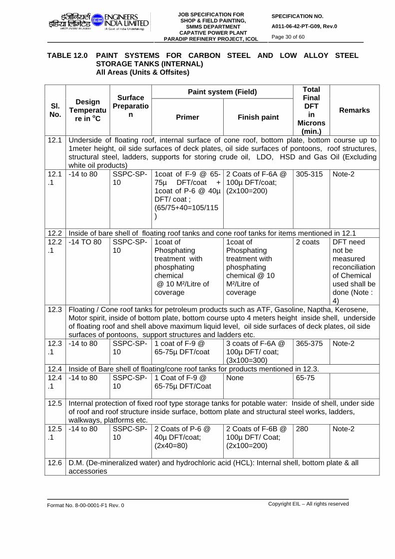
SPECIFICATION NO.
A011-06-42-PT-G09, Rev.0 JOB SPECIFICATION FOR
SHOP & FIELD PAINTING, SMMS DEPARTMENT
CAPATIVE POWER PLANT PARADIP REFINERY PROJECT, ICOL Page 30 of 60
Format No. 8-00-0001-F1 Rev. 0 Copyright EIL – All rights reserved
TABLE 12.0 PAINT SYSTEMS FOR CARBON STEEL AND LOW ALLOY STEEL STORAGE TANKS (INTERNAL) All Areas (Units & Offsites)
Paint system (Field)
Sl. No.
Design Temperatu
re in oC
Surface Preparatio
n
Primer Finish paint
Total Final DFT in
Microns (min.)
Remarks
12.1 Underside of floating roof, internal surface of cone roof, bottom plate, bottom course up to 1meter height, oil side surfaces of deck plates, oil side surfaces of pontoons, roof structures, structural steel, ladders, supports for storing crude oil, LDO, HSD and Gas Oil (Excluding white oil products)
12.1.1
-14 to 80 SSPC-SP-10
1coat of F-9 @ 65-75µ DFT/coat + 1coat of P-6 @ 40µ DFT/ coat ; (65/75+40=105/115)
2 Coats of F-6A @ 100µ DFT/coat; (2x100=200)
305-315 Note-2
12.2 Inside of bare shell of floating roof tanks and cone roof tanks for items mentioned in 12.1 12.2.1
-14 TO 80 SSPC-SP-10
1coat of Phosphating treatment with phosphating chemical @ 10 M²/Litre of coverage
1coat of Phosphating treatment with phosphating chemical @ 10 M²/Litre of coverage
2 coats
DFT need not be measured reconciliation of Chemical used shall be done (Note : 4)
12.3 Floating / Cone roof tanks for petroleum products such as ATF, Gasoline, Naptha, Kerosene, Motor spirit, inside of bottom plate, bottom course upto 4 meters height inside shell, underside of floating roof and shell above maximum liquid level, oil side surfaces of deck plates, oil side surfaces of pontoons, support structures and ladders etc.
12.3.1
-14 to 80 SSPC-SP-10
1 coat of F-9 @ 65-75µ DFT/coat
3 coats of F-6A @ 100µ DFT/ coat; (3x100=300)
365-375 Note-2
12.4 Inside of Bare shell of floating/cone roof tanks for products mentioned in 12.3. 12.4.1
-14 to 80 SSPC-SP-10
1 Coat of F-9 @ 65-75µ DFT/Coat
None 65-75
12.5 Internal protection of fixed roof type storage tanks for potable water: Inside of shell, under side of roof and roof structure inside surface, bottom plate and structural steel works, ladders, walkways, platforms etc.
12.5.1
-14 to 80 SSPC-SP-10
2 Coats of P-6 @ 40µ DFT/coat; (2x40=80)
2 Coats of F-6B @ 100µ DFT/ Coat; (2x100=200)
280 Note-2
12.6 D.M. (De-mineralized water) and hydrochloric acid (HCL): Internal shell, bottom plate & all accessories

SPECIFICATION NO.
A011-06-42-PT-G09, Rev.0 JOB SPECIFICATION FOR
SHOP & FIELD PAINTING, SMMS DEPARTMENT
CAPATIVE POWER PLANT PARADIP REFINERY PROJECT, ICOL Page 31 of 60
Format No. 8-00-0001-F1 Rev. 0 Copyright EIL – All rights reserved
12.6.1
-14 to 60 SSPC-SP-10
None Natural Rubber lining as per SMMS specifications 6-06-204
4.5MM For DM tanks without steam blanketing
12.6.2
61 to150 SSPC-SP-10
1 coat of F-15 primer @ 80µ DFT/ coat
1 coat of F-15 intermediate coat @ 80µ DFT/coat + 1 coat of F-15 finish coat @ 80µ DFT/ coat; (80+80=160)
240 For DM tanks with steam blanketing
12.7 EG(Ethylene Glycol) tanks (internal shell, bottom plate roof and all accessories) 12.7.1
All SSPC-SP-10
None 3 coats of vinyl chloride co-polymer Amercoat 23 @ 75µ /Coat ; (3x75=225)
225
12.8 Inside pontoon and inside of double deck of all floating roofs. 12.8.1
-14 to 80 SSPC-SP-3
1 coat of F-8 @ 100µ DFT/coat
1 coat of F-8 @ 100µ DFT/coat
200
12.9 Internal surfaces of wet slop, amine, sour water , water draw off storage tanks 12.9.1
-14 TO 80 SSPC-SP-10
1 coat of F-15 primer @ 80µ DFT/ coat
1 coat of F-15 intermediate coat @ 80µ DFT/coat + 1 coat of F-15 finish coat @ 80µ DFT/ coat; (80+80=160)
240
12.10
Underside of floating roof, internal surface of cone roof, bottom plate, bottom course up to 4meter height, oil side surfaces of deck plates, oil side surfaces of pontoons, roof structures, structural steel, ladders, supports for storing Vacuum Residue, Fuel oil , dry slop and other high temperature hydrocarbon liquids.
12.10.1
81 TO 150 SSPC-SP-10
1 coat of F-17 primer @ 125µ DFT/ coat
1 coat of F-17 intermediate coat @ 125µ DFT/coat + 1 coat of F-17 finish coat @125µ DFT/ coat; (125+125=250)
375 Note:3
12.11
Inside of Bare shell of floating/cone roof tanks for products mentioned in 12.10
12.11.1
81 TO 150 SSPC-SP-10
1 coat of F-17 primer @ 125µ DFT/ coat
None 125
NOTES
1. If the Pre-erection/Pre-fabrication & Shop Primer has already been completed, the same shall not be repeated again in the field. In case the damages of primer are severe and spread over large areas, the engineer-in-charge may decide & advise re-blasting and

SPECIFICATION NO.
A011-06-42-PT-G09, Rev.0 JOB SPECIFICATION FOR
SHOP & FIELD PAINTING, SMMS DEPARTMENT
CAPATIVE POWER PLANT PARADIP REFINERY PROJECT, ICOL Page 32 of 60
Format No. 8-00-0001-F1 Rev. 0 Copyright EIL – All rights reserved
priming again. Repair of pre-fabrication/pre-erection primer, if required, shall be done as per Table 7.2.
2. F-6A/F6B should be suitable for immersion service of the products given.
3. This system can be used where maximum operating temperature is below 150oC and
design temperature is upto 200oC. Cases of operating temperature > 150oC are not covered in this spec, such cases shall be covered in the job specifications.
4. The phosphating chemical shall be applied on blast cleaned surface inside the shell of
carbon steel storage tanks at the time of erection. Incase, any corrosion is observed at the time of commissioning, 2 coats of the phosphating chemical shall be applied at the discretion of Engineer-in-charge.

SPECIFICATION NO.
A011-06-42-PT-G09, Rev.0 JOB SPECIFICATION FOR
SHOP & FIELD PAINTING, SMMS DEPARTMENT
CAPATIVE POWER PLANT PARADIP REFINERY PROJECT, ICOL Page 33 of 60
Format No. 8-00-0001-F1 Rev. 0 Copyright EIL – All rights reserved
TABLE 13.0 COATING SYSTEM FOR EXTERNAL SIDE OF UNDERGROUND CARBON STEEL PLANT PIPING AND UNDERGROUND TANKS IN ALL AREAS
Paint system (Field)
Sl. No.
Design Temperatu
re in oC
Surface Preparatio
n
Primer Finish paint
Total Final DFT in
Microns (min.)
Remarks
13.1 Underground carbon steel plant piping ( Yard/ Over the Ditch Corrosion protection Coating) 13.1.1
25 to 65
SSPC-SP-10
1 coat of synthetic fast drying primer 25 @µ DFT/ coat
1 layer of coaltar tape coating @ 2mm +1 coat of synthetic fast drying primer 25 @µ DFT/ coat +1 layer of coal tar tape coating @ 2mm /layer as per EIL Standard Spec.No 6-79-0011
4 mm
13.2 Carbon steel plant piping (underground). 13.2.1
66 to 150 SSPC-SP-10
1 coat of F-17 primer @ 125µ DFT/ coat
1 coat of F-17 intermediate coat @ 125µ DFT/coat + 1 coat of F-17 finish coat @125µ DFT/ coat; (125+125=250)
375
13.2.2
151 to 400 SSPC-SP-10
1 coat of F-16 primer @ 125µ DFT/ coat
1 coat of F-16 finish coat @125µ DFT/ coat
250
13.3 External side of un-insulated underground storage tanks: 13.3.1
-40 to 80 SSPC-SP-10
1 coat of F-9 @ 65-75µ DFT/ coat
3 coats of F-7 @ 100µ DFT/coat (3x100=300)
365-375
13.3.2
81 to 150 SSPC-SP-10
1 coat of F-17 primer @ 125µ DFT/ coat
1 coat of F-17 intermediate coat @ 125µ DFT/coat + 1 coat of F-17 finish coat @125µ DFT/ coat; (125+125=250)
375
13.3.2
151 to 400 SSPC-SP-10
1 coat of F-16 primer @ 125µ DFT/ coat
1 coat of F-16 finish coat @125µ DFT/ coat
250
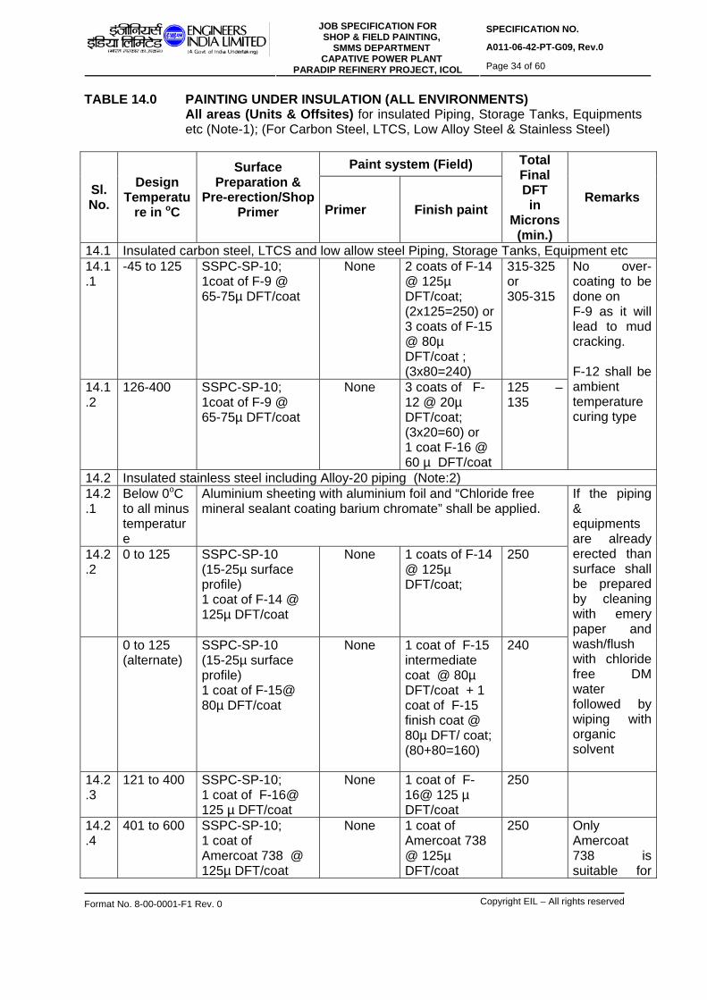
SPECIFICATION NO.
A011-06-42-PT-G09, Rev.0 JOB SPECIFICATION FOR
SHOP & FIELD PAINTING, SMMS DEPARTMENT
CAPATIVE POWER PLANT PARADIP REFINERY PROJECT, ICOL Page 34 of 60
Format No. 8-00-0001-F1 Rev. 0 Copyright EIL – All rights reserved
TABLE 14.0 PAINTING UNDER INSULATION (ALL ENVIRONMENTS) All areas (Units & Offsites) for insulated Piping, Storage Tanks, Equipments
etc (Note-1); (For Carbon Steel, LTCS, Low Alloy Steel & Stainless Steel)
Paint system (Field)
Sl. No.
Design Temperatu
re in oC
Surface Preparation &
Pre-erection/Shop Primer
Primer Finish paint
Total Final DFT in
Microns (min.)
Remarks
14.1 Insulated carbon steel, LTCS and low allow steel Piping, Storage Tanks, Equipment etc 14.1.1
-45 to 125 SSPC-SP-10; 1coat of F-9 @ 65-75µ DFT/coat
None 2 coats of F-14 @ 125µ DFT/coat; (2x125=250) or 3 coats of F-15 @ 80µ DFT/coat ; (3x80=240)
315-325 or 305-315
14.1.2
126-400 SSPC-SP-10; 1coat of F-9 @ 65-75µ DFT/coat
None 3 coats of F-12 @ 20µ DFT/coat; (3x20=60) or 1 coat F-16 @ 60 µ DFT/coat
125 – 135
No over-coating to be done on F-9 as it will lead to mud cracking. F-12 shall be ambient temperature curing type
14.2 Insulated stainless steel including Alloy-20 piping (Note:2) 14.2.1
Below 0oC to all minus temperature
Aluminium sheeting with aluminium foil and “Chloride free mineral sealant coating barium chromate” shall be applied.
14.2.2
0 to 125 SSPC-SP-10 (15-25µ surface profile) 1 coat of F-14 @ 125µ DFT/coat
None 1 coats of F-14 @ 125µ DFT/coat;
250
0 to 125 (alternate)
SSPC-SP-10 (15-25µ surface profile) 1 coat of F-15@ 80µ DFT/coat
None 1 coat of F-15 intermediate coat @ 80µ DFT/coat + 1 coat of F-15 finish coat @ 80µ DFT/ coat; (80+80=160)
240
If the piping & equipments are already erected than surface shall be prepared by cleaning with emery paper and wash/flush with chloride free DM water followed by wiping with organic solvent
14.2.3
121 to 400 SSPC-SP-10; 1 coat of F-16@ 125 µ DFT/coat
None 1 coat of F-16@ 125 µ DFT/coat
250
14.2.4
401 to 600 SSPC-SP-10; 1 coat of Amercoat 738 @ 125µ DFT/coat
None 1 coat of Amercoat 738 @ 125µ DFT/coat
250
Only Amercoat 738 is suitable for

SPECIFICATION NO.
A011-06-42-PT-G09, Rev.0 JOB SPECIFICATION FOR
SHOP & FIELD PAINTING, SMMS DEPARTMENT
CAPATIVE POWER PLANT PARADIP REFINERY PROJECT, ICOL Page 35 of 60
Format No. 8-00-0001-F1 Rev. 0 Copyright EIL – All rights reserved
14.2.5
Cyclic service (-)196 to 480 excepting (-)45 to 120
SSPC-SP-10 1 coat of Amercoat 738 @ 125µ DFT/coat
None 1 coat of Amercoat 738 @ 125µ DFT/coat
250 the temperature of 600 deg.C and cyclic temperature.
14.3 No painting is required for insulated monel, incoloy and nickel lines. NOTES
1. Refer Notes 1 & 4 of Table 8.0. 2. The blast cleaning abrasives for SS and Alloy steel surfaces shall be SS grits/shots or
Aluminium oxide grits/shots. 3. For SS surfaces with cyclic temperature of -45 to125 deg.C, both 14.2.1 & 14.2.2 are
applicable.

SPECIFICATION NO.
A011-06-42-PT-G09, Rev.0 JOB SPECIFICATION FOR
SHOP & FIELD PAINTING, SMMS DEPARTMENT
CAPATIVE POWER PLANT PARADIP REFINERY PROJECT, ICOL Page 36 of 60
Format No. 8-00-0001-F1 Rev. 0 Copyright EIL – All rights reserved
TABLE 15.0 INTERNAL PROTECTION OF CARBON STEEL COOLERS / CONDENSERS Water boxes, channels, partition plates, end covers and tube sheets etc.
Paint system (Field)
Sl. No.
Design Temperatu
re in oC
Surface Preparation &
Pre-erection/Shop Primer
Primer Finish paint
Total Final DFT in
Microns (min.)
Remarks
15.1 Upto 65 SSPC-SP-10; 1 coat of P-6 @ 40µ DFT/coat
None 2 coats of F-7 @ 125µ DFT/coat; (2x125=250)
290 For CS surfaces
15.2 Upto 65
SSPC-SP-3; 1 coat of P-4 @8-10µ DFT/ coat+ 1coat of P-6 @ 40µ DFT/coat.
None 2 coats of F-7 @ 125µ DFT/coat; (2x125=250)
300 (Non ferrous and brass tube sheets)
TABLE 16.0 PAINTING SYSTEM FOR GI TOWERS/NON-FERROUS TUBE SHEET
Paint system (Field)
Sl. No.
Design Temperatu
re in oC
Surface Preparation &
Pre-erection/Shop Primer
Primer Finish paint
Total Final DFT in
Microns (min.)
Remarks
16.1 Upto 65 SSPS-SP-3 1 coat of P-4 @8-10µ DFT/ coat + 1 coat of P-6 @ 40µ DFT/coat
2 coats of F-2 @ 40µ DFT/coat; (2x40=80)
130 Shade as per defence requirements
16.2 Upto 65
SSPS-SP-3 1 coat of P-4 @ 8µ DFT/coat.+ 1 coat of P-6 @ 40µ DFT/coat.
2 coats of F-7 @ 125µ DFT/coat; (2x125=250)
300 (Non ferrous and brass tube sheets)

SPECIFICATION NO.
A011-06-42-PT-G09, Rev.0 JOB SPECIFICATION FOR
SHOP & FIELD PAINTING, SMMS DEPARTMENT
CAPATIVE POWER PLANT PARADIP REFINERY PROJECT, ICOL Page 37 of 60
Format No. 8-00-0001-F1 Rev. 0 Copyright EIL – All rights reserved
17.0 SHOP & FIELD PAINTING SYSTEM FOR EFFLUENT TREATMENT PLANT
Paint System Sl. No.
Design Temperature
in oC Surface
Preparation Primer Finish Paint
Total DFT in Microns
(min.)
Remarks
17.1 -14 to 80(for C.S./M.S. items): Screens, Walk way bridges, Baffles, Dual media filters(external) Vertical pumps, piping in treated effluent sump and pump house, external side lining of Slop oil MS tank
SSPS-SP-10 1 coat of F-9 @ 65-75µ DFT/coat
3 coats of F-6A @100µ DFT/coat 3x100=300
365
17.2 -14 to 80(CS/MS Items) for Vertical pump and piping in, Bio-sludge sump and pump, Filter feed sump and pump, Process sump, Sanitary sump; Transfer sump, Sludge, MS Slop oil tank internal, scrapping mechanism in Clarifier, Screw pump
SSPS-SP-10 1 coat of F-9 @ 65-75µ DFT/coat.
2 coats of F-6A @100µ DFT/coat
265
17.3 -14 to 80 deg.C :All R.C.C. surfaces such as tanks, structures, drains etc.) in Process sump, TPI separator (Process and Oil), Aeration Tank, Transfer sump etc.
Blast cleaning to SSPC-SP guide lines and Acid etching with 10-15% Hcl acid followed by thorough water washing.
As per SMMS-EIL specification for Epoxy screed lining No.6-06-209 (latest Revision)
As per SMMS-EIL specifications for Epoxy screed lining as per 6-06-209 (latest Revision)
3mm Epoxy screed lining shall be used as per specific instructions from Engineer-in-Charge at site.
17.4 Upto 60 deg. C C.S/M.S Dual media filters (Internal), Chemical dosing tanks(internal such as DAP, Urea
SSPC-SP-10 - Rubber Lining as per SMMS-EIL Spec. 6-06-204 Rev.4 (Latest revision)
4.5mm

SPECIFICATION NO.
A011-06-42-PT-G09, Rev.0 JOB SPECIFICATION FOR
SHOP & FIELD PAINTING, SMMS DEPARTMENT
CAPATIVE POWER PLANT PARADIP REFINERY PROJECT, ICOL Page 38 of 60
Format No. 8-00-0001-F1 Rev. 0 Copyright EIL – All rights reserved

SPECIFICATION NO.
A011-06-42-PT-G09, Rev.0 JOB SPECIFICATION FOR
SHOP & FIELD PAINTING, SMMS DEPARTMENT
CAPATIVE POWER PLANT PARADIP REFINERY PROJECT, ICOL Page 39 of 60
Format No. 8-00-0001-F1 Rev. 0 Copyright EIL – All rights reserved
18.0 STORAGE 18.1 All paints and painting materials shall be stored only in rooms to be arranged by
contractor and approved by Engineer-in-charge for the purpose. All necessary precautions shall be taken to prevent fire. The storage building shall preferably be separate from adjacent building. A signboard bearing the word “PAINT STORAGE – NO NAKED LIGHT – HIGHLY INFLAMABLE” shall be clearly displayed outside. Manufacturer’s recommendation shall be followed for storage of paint materials.
19.0 PIPING COLOUR CODE:
The following colour coding system has been made based on international standards like ASME/ ANSI, BS and Indian Standard.
19.1 IDENTIFICATION
The system of colour coding consists of a ground colour and secondary colour bands superimposed over the ground colour. The ground colour identifies the basic nature of the service and secondary colour band over the ground colour distinguishes the particular service. The ground colour shall be applied over the entire length of the un-insulated pipes. For insulated lines ground colour shall be provided as per specified length and interval to identify the basic nature of service and secondary colour bands to be painted on these specified length to identify the particular service. Above colour code is applicable for both unit and offsite pipelines.
19.1.1 The following ground colour designation for identification of basic classification of various
important services shall be followed: Post Office Red - Fire protection materials Off White/Aluminium - Steam (all pressures) Canary Yellow - Chemicals and dangerous materials Dark Admiralty Grey - Crude oil, lube oil Orange - Volatile petroleum products (motor spirit and
lighter) Oxide red - Non-volatile petroleum products (kerosene and
heavier, including waxy distillates and diesel, gas oil)
Black - Residual oils, still bottoms, slop oils and asphalts, fuel oil
Sky blue - Water (all purities and temperatures) Sea green - Air and its components and Freon
19.1.2 Secondary colours: The narrow bands presenting the secondary colour which identifies
the specific service, may be applied by painting or preferably by use of adhesive plastic tapes of the specific colour.
19.2 COLOUR BANDS AND IDENTIFICATION LETTERING
19.2.1 The following specifications of colour bands shall be followed for identifying the piping
contents, size and location of bands & letters. The bandwidth and size of letters in legends will depend to some extent upon the pipe diameter. Either white or black letters are selected to provide maximum contrast to the band colour. Bands usually are 50 mm

SPECIFICATION NO.
A011-06-42-PT-G09, Rev.0 JOB SPECIFICATION FOR
SHOP & FIELD PAINTING, SMMS DEPARTMENT
CAPATIVE POWER PLANT PARADIP REFINERY PROJECT, ICOL Page 40 of 60
Format No. 8-00-0001-F1 Rev. 0 Copyright EIL – All rights reserved
wide and regardless of band width, are spaced 25 mm apart when two bands are employed
Table 1.0: Colour bands and size of lettering for piping: In addition, ground colour as per specified length should be provided on insulated piping for easy identification of nature of fluid, on which the colour bands should be painted for identification of each service. The length of the ground colour should be 3 times the width of normal band or 2 meters, whichever is suitable depending on the length of the pipe.
Size of letters stenciled/ written for equipment shall be as given below:
Column and vessel : 150 mm (Height) Pump, compressor and other machinery : 50 mm (Height)
In addition, the contents of the pipe and/or direction of flow may be further indicated by arrows and legend. If a hazard is involved it must be identified clearly by legend.
19.2.2 Colour bands: The location and size of bands, as recommended, when used,
shall be applied to the pipe:
- On both sides of the valves, tees and other fittings of importance. - Where the pipe enters and emerges from walls and where it emerges from
road & walkway overpasses, unit battery limits. - At uniform intervals along long sections of the pipe. - Adjacent to tanks, vessels, and pumps.
19.2.2 For piping, writing of name of service and direction of flow for all the lines shall be done
at following locations: 19.2.3 The letters will be in black on pipes painted with light shade colours and white on pipes
painted with dark shade colours to give good contrast. 19.2.4 Only writing of service name shall be done on stainless steel lines. Precautions should
be taken while painting by using low chloride content painting to avoid any damage to the stainless steel pipes. It is preferable to use adhesive plastic tapes to protect stainless steel pipes.
19.2.5 Colour band specification:
a) Unit Area: Bands at intervals of 6.0 meters. Offsite Area: Bands at intervals of 10.0 meters.
Outside diameter of pipe or covering in
mm
Width of colour bands in mm
Size of legend letters in mm
19 to 32 200 13 38 to 51 200 19
64 to 150 300 32 200 to 250 600 64 Over 250 800 89
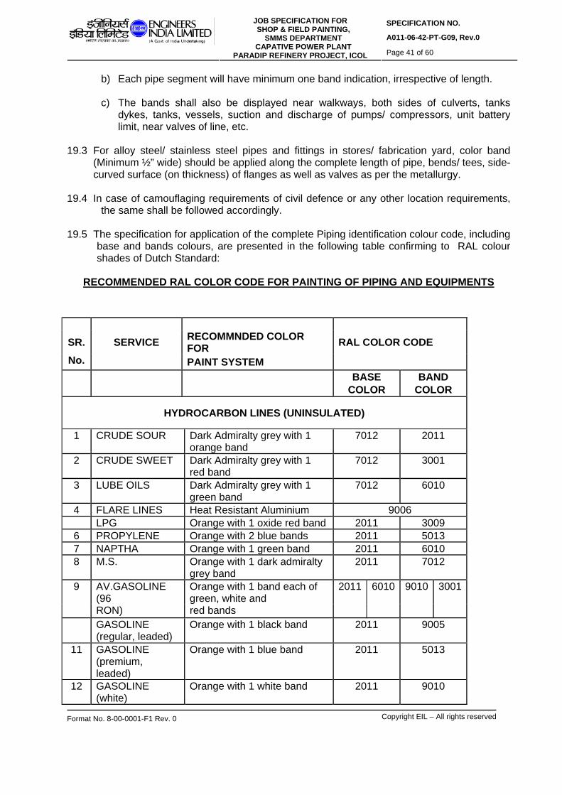
SPECIFICATION NO.
A011-06-42-PT-G09, Rev.0 JOB SPECIFICATION FOR
SHOP & FIELD PAINTING, SMMS DEPARTMENT
CAPATIVE POWER PLANT PARADIP REFINERY PROJECT, ICOL Page 41 of 60
Format No. 8-00-0001-F1 Rev. 0 Copyright EIL – All rights reserved
b) Each pipe segment will have minimum one band indication, irrespective of length. c) The bands shall also be displayed near walkways, both sides of culverts, tanks
dykes, tanks, vessels, suction and discharge of pumps/ compressors, unit battery limit, near valves of line, etc.
19.3 For alloy steel/ stainless steel pipes and fittings in stores/ fabrication yard, color band
(Minimum ½” wide) should be applied along the complete length of pipe, bends/ tees, side-curved surface (on thickness) of flanges as well as valves as per the metallurgy.
19.4 In case of camouflaging requirements of civil defence or any other location requirements,
the same shall be followed accordingly. 19.5 The specification for application of the complete Piping identification colour code, including
base and bands colours, are presented in the following table confirming to RAL colour shades of Dutch Standard:
RECOMMENDED RAL COLOR CODE FOR PAINTING OF PIPING AND EQUIPMENTS
SR. SERVICE RECOMMNDED COLOR FOR RAL COLOR CODE
No. PAINT SYSTEM BASE BAND COLOR COLOR
HYDROCARBON LINES (UNINSULATED)
1 CRUDE SOUR Dark Admiralty grey with 1 orange band
7012 2011
2 CRUDE SWEET Dark Admiralty grey with 1 red band
7012 3001
3 LUBE OILS Dark Admiralty grey with 1 green band
7012 6010
4 FLARE LINES Heat Resistant Aluminium 9006 LPG Orange with 1 oxide red band 2011 3009
6 PROPYLENE Orange with 2 blue bands 2011 5013 7 NAPTHA Orange with 1 green band 2011 6010 8 M.S. Orange with 1 dark admiralty
grey band 2011 7012
9 AV.GASOLINE (96
Orange with 1 band each of green, white and
2011 6010 9010 3001
RON) red bands GASOLINE
(regular, leaded) Orange with 1 black band 2011 9005
11 GASOLINE (premium, leaded)
Orange with 1 blue band 2011 5013
12 GASOLINE (white)
Orange with 1 white band 2011 9010

SPECIFICATION NO.
A011-06-42-PT-G09, Rev.0 JOB SPECIFICATION FOR
SHOP & FIELD PAINTING, SMMS DEPARTMENT
CAPATIVE POWER PLANT PARADIP REFINERY PROJECT, ICOL Page 42 of 60
Format No. 8-00-0001-F1 Rev. 0 Copyright EIL – All rights reserved
13 GASOLINE (Aviation
Orange with 1 red band 2011 3001
100/130) 14 GASOLINE
(Aviation 115/145)
Orange with 1 purple band 2011 4006
N-PENTANE Orange with 2 blue bands 2011 5013
16 DIESEL OIL (White) Oxide red with 1 white band 3009 9010
17 DIESEL OIL (Black)
Oxide red with 1 yellow band 3009 1023
18 KEROSENE Oxide red with 1 green band 3009 6010 19 HY.KEROSENE Oxide red with 2 green bands 3009 6010
DISUFIDE OIL (EX-
Oxide red with 1 black band 3009 9005
MEROX) 21 M.T.O Oxide red with 3 green bands 3009 6010 22 DHPPA Oxide red with 2 white bands 3009 9010 23 FLUSHING OIL Oxide red with 2 black bands 3009 9005 24 LAB FS Oxide red with 2 dark
admiralty grey bands 3009 7012
LAB RS Oxide red with 3 dark admiralty grey bands
3009 7012
26 LAB (Off. Spec) Oxide red with 1 light grey band
3009 7035
27 N-PARAFFIN Oxide red with 1-blue band 3009 5013 28 HEAVY
ALKYLATE Oxide red with red band 3009 3001
29 BLOW DOWN,
VAPOR LINE Off white / Aluminum with 1-Brown band
9006 8004
30 BLOWDOWN Off white / Aluminum with 2 brown bands
9006 8004
31 A.T.F. Leaf brown with 1 white band 8003 9010 32 TOULENE Leaf brown with 1 yellow band 8003 1023 33 BENZENE Leaf brown with 1 green band 8003 6010 34 LAB PRODUCT Leaf brown with 1 blue band 8003 5013 35 FUEL OIL Black with 1 yellow band 9005 1023 36 FULE OIL
(Aromatic rich) Black with 2 yellow bands 9005 1023
37 ASPHALT Black with 1 white band 9005 9010 38 SLOP AND WASTE
OILS Black with 1 orange band 9005 2011
39 SLOP AROMATICS Black with 2 orange bands 9005 2011
CHEMICAL LINES
40 TRI-SODIUM PHOSPHATE
Canary yellow with 1 violet band 1012 5000
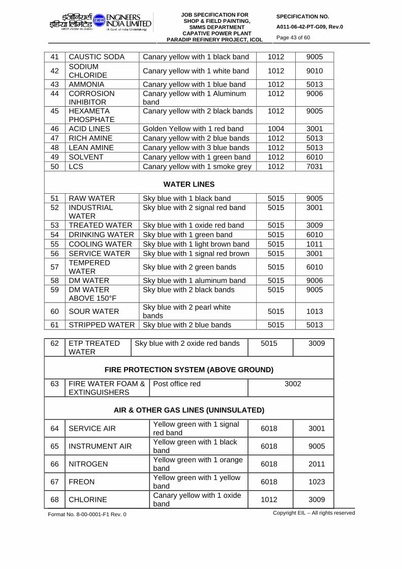
SPECIFICATION NO.
A011-06-42-PT-G09, Rev.0 JOB SPECIFICATION FOR
SHOP & FIELD PAINTING, SMMS DEPARTMENT
CAPATIVE POWER PLANT PARADIP REFINERY PROJECT, ICOL Page 43 of 60
Format No. 8-00-0001-F1 Rev. 0 Copyright EIL – All rights reserved
41 CAUSTIC SODA Canary yellow with 1 black band 1012 9005
42 SODIUM CHLORIDE Canary yellow with 1 white band 1012 9010
43 AMMONIA Canary yellow with 1 blue band 1012 5013 44 CORROSION
INHIBITOR Canary yellow with 1 Aluminum band
1012 9006
45 HEXAMETA PHOSPHATE
Canary yellow with 2 black bands 1012 9005
46 ACID LINES Golden Yellow with 1 red band 1004 3001 47 RICH AMINE Canary yellow with 2 blue bands 1012 5013 48 LEAN AMINE Canary yellow with 3 blue bands 1012 5013 49 SOLVENT Canary yellow with 1 green band 1012 6010 50 LCS Canary yellow with 1 smoke grey 1012 7031
WATER LINES
51 RAW WATER Sky blue with 1 black band 5015 9005 52 INDUSTRIAL
WATER Sky blue with 2 signal red band 5015 3001
53 TREATED WATER Sky blue with 1 oxide red band 5015 3009 54 DRINKING WATER Sky blue with 1 green band 5015 6010 55 COOLING WATER Sky blue with 1 light brown band 5015 1011 56 SERVICE WATER Sky blue with 1 signal red brown 5015 3001
57 TEMPERED WATER Sky blue with 2 green bands 5015 6010
58 DM WATER Sky blue with 1 aluminum band 5015 9006 59 DM WATER
ABOVE 150°F Sky blue with 2 black bands 5015 9005
60 SOUR WATER Sky blue with 2 pearl white bands 5015 1013
61 STRIPPED WATER Sky blue with 2 blue bands 5015 5013 62 ETP TREATED
WATER Sky blue with 2 oxide red bands 5015 3009
FIRE PROTECTION SYSTEM (ABOVE GROUND)
63 FIRE WATER FOAM & EXTINGUISHERS
Post office red 3002
AIR & OTHER GAS LINES (UNINSULATED)
64 SERVICE AIR Yellow green with 1 signal red band
6018 3001
65 INSTRUMENT AIR Yellow green with 1 black band
6018 9005
66 NITROGEN Yellow green with 1 orange band
6018 2011
67 FREON Yellow green with 1 yellow band
6018 1023
68 CHLORINE Canary yellow with 1 oxide band
1012 3009

SPECIFICATION NO.
A011-06-42-PT-G09, Rev.0 JOB SPECIFICATION FOR
SHOP & FIELD PAINTING, SMMS DEPARTMENT
CAPATIVE POWER PLANT PARADIP REFINERY PROJECT, ICOL Page 44 of 60
Format No. 8-00-0001-F1 Rev. 0 Copyright EIL – All rights reserved
69 SO2 Canary yellow with 2 white bands
1012 9010
70 H2S Orange with 2 red oxide bands
2011 3009
71 GAS (Fuel) Orange with 1 aluminum band
2011 9006
72 GAS (Sour) Orange with 2 aluminum bands 2011 9006
73 GAS (Sweet) Orange with 2 signal red band
2011 3001
74 HYDROGEN Orange with 1 light green band
2011 6021
STEAM AND CONDENSATE LINES (UNINSULATED)
75 HP STEAM Off white / Aluminum with 1 yellow band
9006 1023
76 MP STEAM Off white / Aluminum with 1 red band
9006 3001
77 MLP STEAM Off white / Aluminum with 1 orange band
9006 2011
78 LP STEAM Off white / Aluminum with 1 light green band
9006 6021
79 CONDENSATE Sky blue with 1 white band 5015 9010 80 CONDENSATE
ABOVE 150°F Sky blue with 3 oxide red band
5015 3009
81 BFW Sky blue with 2 red bands 5015 3001 Note: For all insulated steam lines, the colour coding shall be follow as given for un-insulated lines with the specified length of color bands.
INSULATED HYDROCARBON PIPING
82 IFO SUPPLY 1Black ground colour with 1 yellow band in centre 9005 1023
83 IFO RETURN Black ground colour with 1 green band in centre
9005 6010
84 HPS Black ground colour with 1 red band in centre
9005 3001
85 BITUMEN Black ground colour with 2 red bands in centre
9005 3001
86 CLO Black ground colour with 1
brown band in centre 9005 8004
87 VB TAR Black ground colour with 2 brown bands in centre
9005 8004
88 VR AM (BITUMEN / VBU FEED)
1 Black ground colour with 1 blue band in centre
9005 5013
89 VR BH 1 Black ground colour with 2 blue bands in centre
9005 5013

SPECIFICATION NO.
A011-06-42-PT-G09, Rev.0 JOB SPECIFICATION FOR
SHOP & FIELD PAINTING, SMMS DEPARTMENT
CAPATIVE POWER PLANT PARADIP REFINERY PROJECT, ICOL Page 45 of 60
Format No. 8-00-0001-F1 Rev. 0 Copyright EIL – All rights reserved
90 VAC. SLOP 1 Black ground colour with 1 white band in centre
9005 9010
91 SLOP 1 Black ground colour with 1 orange band in centre
9005 2011
92 CRUDE SWEET 1 Dark admiralty grey ground colour with 1 red band in centre
7012 3001
93 CRUDE OUR 1 Dark admiralty grey ground colour with 1 orange band in centre
7012 2011
94 VGO / HCU 1 Oxide red ground colour with 2 steel grey bands in centre
3009 7011
95 OHCU BOTOM / FCCU FEED
1 Oxide red ground colour with 2 steel grey bands in centre
3009 7011
UNINSULATED EQUIPMENTS, TANKS AND STRUCTURES
96 HEATER STRUCTURE Steel grey 7011 97 HEATER CASING Heat resistant
aluminium 9006
98 VESSELS & COLUMNS Aluminium 9006 99 HYDROGEN BULLETS Pink 3014
100 LPG VESSELS Oxide red 3009 101 SO2 VESSEL Canary yellow 1012
102 HEAT EXCHANGER Heat resistant aluminium
9006
103 FO TANK AND HOT TANKS Black 9005 104 ALL OTHER TANKS Aluminum / Off white 9006
105 CAUSTIC / AMINE / ACID TANKS Golden yellow 1004
106 SOUR WATER Sky Blue 5015 107 OUTER SURFACE IN
BOILER HOUSE Heat resistant aluminum
9006
108 COMPRESSORS AND BLOWERS Dark admiralty grey 7012
109 PUMPS Navy blue 5014
110 Electrical Equipment – Indore Pebbel grey 7032
111 Electrical Equipment - Outdoor Blue grey 7031
112 HAND RAILING Fluorescent yellow 1026 113 STAIRCASE, LADDER AND
WALKWAYS Black 9005
114 LOAD LIFTING EQUIPMENT AND MONORAILS ETC
Leaf brown 8003

SPECIFICATION NO.
A011-06-42-PT-G09, Rev.0 JOB SPECIFICATION FOR
SHOP & FIELD PAINTING, SMMS DEPARTMENT
CAPATIVE POWER PLANT PARADIP REFINERY PROJECT, ICOL Page 46 of 60
Format No. 8-00-0001-F1 Rev. 0 Copyright EIL – All rights reserved
115 GENERAL STRUCTURE Dark grey 7031 116 LOCAL PANEL FACE Opaline green 6026 117 PANEL REAR SURFACE,
FRAME WORK & MOUNTING PLATES
Pale cream 9001
118 MONORAIL Signal red 3001
PIPES AND FITTINGS OF ALLOY STEEL AND SS MATERIAL IN STORE
119 IBR Signal red 3001 120 9Cr-1Mo Verdigris green 6021 121 5Cr-0.5Mo Satin blue 5012
1 22
21/4Cr-1 Mo Aircraft yellow 1026
123 11/4Cr-½ Mo Traffic Yellow 1023 124 SS-304 Dark blue grey 5008 125 SS-316 Dark violet 4005 126 SS-321 Navy blue 5014
SAFETY COLOUR SCHEMES
127 DANGEROUS OBSTRUCTION
Black and alert orange band 9005 2008
128 DANGEROUS OR EXPOSED PARTS OF MACHINERY
Alert orange 2008
RAL COLOR CODING FOR PETROCHEMICAL COMPLEX
RAL COLOR CODE Sr. No. SERVICE
RECOMMENDED COLOR FOR
PAINT SYSTEM BASE COLOR
BAND COLOR
REFINERY PRODUCTS
1 NATURAL GAS Orange with 3 Oxide red bands 2011 3009
2 PROPANE Orange with 3 Blue band 2011 5013 3 METHANE Orange with 1 Brown band 2011 8004 4 CYCLOHEXANE Orange with 1 Pearl night blue
band 2011 5026
5 n-HEXANE Orange with 1 Pearl green bend 2011 6035 6 ETHANE Orange with 4 Blue bands 2011 5013
7 BLENDED FUEL OIL
Black with 3 Yellow bands 9005 1023

SPECIFICATION NO.
A011-06-42-PT-G09, Rev.0 JOB SPECIFICATION FOR
SHOP & FIELD PAINTING, SMMS DEPARTMENT
CAPATIVE POWER PLANT PARADIP REFINERY PROJECT, ICOL Page 47 of 60
Format No. 8-00-0001-F1 Rev. 0 Copyright EIL – All rights reserved
8 ETHYLENE OXIDE
Orange with 3 Green bands 2011 6010
9 POLYMER PELLETS & SLURRY
Brown beige with 1 white bands 1011 9010
10 HDPE PELLETS Brown beige with 2 white bands 1011 9010
11 WAX Oxide Red with 1 Pastel Green Band 3009 6019
12 GLYCOL Canary yellow with 1 Pearl gentian blue 1012 5025
13 BUTADIENE < 15%
Orange with 1 band Pastel Green band 2011 6019
14 BUTADIENE 5 -95%
Orange with 2 Pastel Green bands
2011 6019
15 BUTADIENE > 95%
Orange with 3 Pastel Green bands 2011 6019
16 ALDEHYDE SOLUTION
Sky blue with 1 orange band 5015 2011
17 OCTENE-1 Orange with 1 Blue, 1 Black and 1 Blue
20 5013 50
band 11 90 13 05
18 ETHYLENE Orange with 2 Blue bands + 1 Black band 2011 5013 9005
19 PROPYLENE Orange with 2 Oxford blue bands 2011 5013 20 BUTENE -1 Orange with 2 Red band 2011 3001 21 HEXANE Orange with 2 White bands 2011 9010
22 MEG Canary yellow with 1 Blue lilac band 1012 4005
23 DEG Canary yellow with 2 Blue lilac band 1012 4005
24 TEG Canary yellow with 3 Blue lilac band 1012 4005
25 POLYGLYCOL Canary yellow with 3 Green band 1012 6010
26 GLYCOL / WATER SOLUTION
Canary yellow with 1 Sky blue band 1023 5015
27 DTA Canary yellow with 2 Green band 1012 6010 28 OXYGEN Yellow green with 1 Blue band 6018 5013
29 CYCLE GAS SYSTEM
Oxide red with 2 Purple band 3009 4006
CHEMICALS
29 ISOPRENYL ALUMINUM
Canary yellow with 1 copper brown bands 1012 8004
30 MAGNESIUM ETHYLATE
Canary yellow with 2 copper brown bands 1012 8004
31 TITANIUM TETRA CHLORIDE
Canary yellow with 1 chocolate brown band 1012 8017
32 SULPHURIC ACID Golden Yellow with 3 red bands 1004 3001

SPECIFICATION NO.
A011-06-42-PT-G09, Rev.0 JOB SPECIFICATION FOR
SHOP & FIELD PAINTING, SMMS DEPARTMENT
CAPATIVE POWER PLANT PARADIP REFINERY PROJECT, ICOL Page 48 of 60
Format No. 8-00-0001-F1 Rev. 0 Copyright EIL – All rights reserved
33 CALCIUM HYDROXIDE Canary yellow with 3 black bands 1012 9005
34 SODIUM CHLORIDE Canary yellow with 1 white band 1012 9010
35 FERRIC CHLORIDE
Canary Yellow with 3 red oxide bands 1012 3009
36 SODIUM BI SULFIDE Canary yellow with 3 white bands 1012 9010
37 CHLORINE DIOXIDE Canary yellow with 1 orange band 1012 2011
38 HYDRAZINE Canary yellow with 3 blue bands 1012 5013 39 CARBON DIOXIDE Orange with 4 Aluminum bands 2011 9006
40 CARBON MONOXIDE Orange with 3 Aluminum bands 2011 9006
41 TEAL Dark admiralty grey with 2 white bands 7012 9010
42 LIQUID PEROXIDE Canary yellow with 1 red and 1 blue band 1023 3001 5013
43 CATALYST LINE Canary yellow with 2 Red band 1023 3001 44 CO-CATALYST LINE Canary yellow with 3 Red band 1023 3001
45 EO / WATER SOLUTION Sky blue with 3 Green bands 5015 6010
46 BCWS / BCSWR Sky blue with 1 Brown Biege band 5015 1011
WATER
47 CYCLE WATER- LEAN Sky blue with 2 blue lilac bands 5015 4005
48 CYCLE WATER- RICH Sky blue with 3 blue lilac bands 5015 4005
49 JACKET WATER Sky blue with 3 black bands 5015 9005
50 JACKET WATER-BIOCIDE Sky blue with 2 aluminum bands 5015 9006
51 JACKET WATER-CORROSION INHIBITOR
Sky blue with 3 aluminum bands 5015 9006
52 CHLORINATED WATER Sky blue with 1 green band 5015 6010
53 BACK FLUSH WATER Sky blue with 3 signal red bands 5015 3001
54 CUTTING WATER Sky blue with 1 orange band 5015 2011
55 REFRIGERATED WATER Sky blue with 2 violet blue bands 5015 5000
56 WASTE WATER Sky blue with 2 Signal red bands 5015 3001
INTERMEDIATES
57 MOTHER LIQUOR SOLUTION Orange with 3 pebble grey bands 2011 7032

SPECIFICATION NO.
A011-06-42-PT-G09, Rev.0 JOB SPECIFICATION FOR
SHOP & FIELD PAINTING, SMMS DEPARTMENT
CAPATIVE POWER PLANT PARADIP REFINERY PROJECT, ICOL Page 49 of 60
Format No. 8-00-0001-F1 Rev. 0 Copyright EIL – All rights reserved
58 ADDITIVES SOLUTION Pearl green with 2 white band 6035 9010
59 DEACTIVATORS Pearl green with 2 orange band 6035 2011 60 OFF GAS Pearl green with 2 yellow band 6035 1023
61 OFF GAS PLUS POLYMER Pearl green with 2 Aluminum bands 6035 9006
62 RA SOLUTION Pearl green with 2 oxide red bands 6035 3009 63 DONOR Pearl green with 2 black bands 6035 9005
STEAM
64 VHP Offwhite / Aluminium with 2 yellow band 9006 1023
65 MHP STEAM (20 KG / CM2 G)
Off white / Aluminium with 3 yellow bands
9006 1023
66 OTHER PROCESS LINES e.g. PROCESS STEAM, PROCESS CONDENSATE, PROCESS VENTS.
Light grey with 1Trafffic yellow band 7035 1023
67 DECOKING AIR Yellow Green with 1 Terrabrown band 6018 8028
68 RPG Orange with 1 Yellow Green band 2011 6018 69 C6-C8 CUT Orange with 1 terrabrown band 2011 8028 70 C4 MIX Orange with 1 peral black berry band 2011 4012 71 C9+ CUT / FLUX OIL Orange with 2 grey Beige band 2011 1019 72 C4 PURGE / C4 MIX Orange with 2 peral black berry 2011 4012 73 C9 CUT Orange with 1 grey beige 2011 1019 74 C7-C8 CUT Orange with 2 terra Brown band 2011 8028 75 C3 Orange with 1 Sky blue band 2011 5015 76 PP RECYCLE Orange with 1 water blue 2011 5021 77 PLANT AIR Yellow green with 1 peral light grey 6018 9022 78 AROMATIC Black with 1 water blue 9005 5021 79 LIGHT
DISTILLATION Orange with 1 Solman pink band 2011 3022
80 C9+ Orange with 3 grey beige 2011 1019 81 OWS-OIL WATER
SEWER Sky blue with 1 band of salmon orange
5015 2012
82 CRWS-CONTAMINATED RAIN WATER SEWER
Sky blue with 2 bands of salmon orange
5015 2012
83 CRYOGENIC TANK (RCC)
Orange 2011
20.0 IDENTIFICATION OF VESSELS, PIPING ETC. 20.1 Equipment number shall be stencilled in black or white on each vessel, column,
equipment & machinery (insulated or uninsulated) after painting. Line number in black

SPECIFICATION NO.
A011-06-42-PT-G09, Rev.0 JOB SPECIFICATION FOR
SHOP & FIELD PAINTING, SMMS DEPARTMENT
CAPATIVE POWER PLANT PARADIP REFINERY PROJECT, ICOL Page 50 of 60
Format No. 8-00-0001-F1 Rev. 0 Copyright EIL – All rights reserved
or white shall be stencilled on all the pipe lines of more than one location as directed by Engineer-In-Charge, Size of letter printed shall be as below :
Column & Vessels - 150mm (high) Pump, compressor & other machinery - 50mm (high) Piping - 40-150 mm 20.2 Identification of storage tanks:
The storage tanks shall be marked as detailed in the drawing. 21.0 PAINTING FOR CIVIL DEFENCE REQUIREMENTS 21.1 Following items shall be painted for camouflaging if required by the client. a. All Columns
b. All tanks in Offsites c. Large Vessels d. Spheres
21.2 Two coats of selected finishing paint as per defence requirement shall be applied in a
particular pattern as per 20.3 and as per the instructions of Engineer-In-Charge. 21.3 Method of Camouflaging 21.3.1 Disruptive painting for camouflaging shall be done in three colours in the ratio of 5:3:2
(all matt finish). Dark Green Light Green Dark Medium Brown 5: 3: 2 21.3.2 The patches should be asymmetrical and irregular. 21.3.3 The patches should be inclined at 30º to 60º to the horizontal. 21.3.4 The patches should be continuous where two surfaces meet at an angle. 21.3.5 The patches should not coincide with corners. 21.3.6 Slits and holes shall be painted in dark shades. 21.3.7 Width of patches should be 1 to 2 meters. 22.0 INSPECTION AND TESTING 22.1 All painting materials including primers and thinners brought to site by contractor for
application shall be procured directly from manufactures as per specifications and shall be accompanied by manufacturer's test certificates. Paint formulations without certificates are not acceptable.
22.2. Engineer-In-Charge at his discretion, may call for tests for paint formulations. Contractor
shall arrange to have such tests performed including batch-wise test of wet paints for physical & chemical analysis as per clause 24.4 of relevant ASTM test method. All costs there shall be borne by the contractor.

SPECIFICATION NO.
A011-06-42-PT-G09, Rev.0 JOB SPECIFICATION FOR
SHOP & FIELD PAINTING, SMMS DEPARTMENT
CAPATIVE POWER PLANT PARADIP REFINERY PROJECT, ICOL Page 51 of 60
Format No. 8-00-0001-F1 Rev. 0 Copyright EIL – All rights reserved
The contractor shall produce test reports from manufacturer regarding the quality of the
particular batch of paint supplied. The Engineer-in-Charge shall have the right to test wet samples of paint at random for quality of same. Batch test reports of the manufacturer's for each batch of paints supplied shall be made available by the contractor.
22.3 The painting work shall be subject to inspection by Engineer-In-Charge at all times. In
particular, following stage-wise inspection will be performed and contractor shall offer the work for inspection and approval of every stage before proceeding with the next stage. The record of inspection shall be maintained in the registers. Stages of inspection are as follows:
(a) Surface preparation (b) Primer application (c) Each coat of paint
In addition to above, record should include type of shop primer already applied on equipment e.g. Red oxide zinc chromate or zinc chromate or Red lead primer etc.
Any defect noticed during the various stages of inspection shall be rectified by the contractor to the entire satisfaction of Engineer-In-Charge before proceeding further. Irrespective of the inspection, repair and approval at intermediate stages of work, contractor shall be responsible for making good any defects found during final inspection/guarantee period/defect liability period as defined in general condition of contract. Dry film thickness (D F T)) shall be checked and recorded after application of each coat and extra coat of paint should be applied to make-up the DFT specified without any extra cost to owner, the extra coat should have prior approval of Engineer-in-charge.
22.4 Primer Application
After surface preparation, the primer should be applied to cover the crevices, corners, sharp edges etc. in the presence of inspector nominated by Engineer-In-Charge.
22.5 The shades of successive coats should be slightly different in colour in order to ensure
application of individual coats, the thickness of each coat and complete coverage should be checked as per provision of this specification. This should be approved by Engineer-In-Charge before application of successive coats.
22.6 The contractor shall provide standard thickness measurement instrument with
appropriate range(s) for measuring.
Dry film thickness of each coat, surface profile gauge for checking of surface profile in case of sand blasting. Holiday detectors and pinhole detector and protector whenever required for checking in case of immersion conditions.
22.7 Prior to application of paints on surfaces of chimneys, the thickness of the individual
coat shall be checked by application of each coat of same paint on M.S.test panel. The thickness of paint on test panels shall be determined by using gauge such as 'Elkometer'. The thickness of each coat shall be checked as per provision of this specification. This shall be approved by Engineer-In-Charge before application of paints on surface of chimney.
SPECIFICATION NO.
A011-06-42-PT-G09, Rev.0 JOB SPECIFICATION FOR
SHOP & FIELD PAINTING, SMMS DEPARTMENT
CAPATIVE POWER PLANT PARADIP REFINERY PROJECT, ICOL Page 52 of 60
Format No. 8-00-0001-F1 Rev. 0 Copyright EIL – All rights reserved
22.8 At the discretion of Engineer-In-Charge, the paint manufacturer must provide the expert
technical service at site as and when required. This service should be free of cost and without any obligation to the owner, as it would be in the interest of the manufacturer to ensure that both surface preparation and application are carried out as per their recommendations. The contractor is responsible to arrange the same.
22.9 Final inspection shall include measurement of paint dry film thickness, Adhesion, Holiday
detection check of finish and workmanship. The thickness should be measured at as many points/ locations as decided by Engineer-In-Charge and shall be within + 10% of the dry film thickness, specified in the specifications.
22.10 The contractor shall arrange for spot checking of paint materials for Sp.gr., glow time
(ford cup) and spreading rate. 23.0 GUARANTEE 23.1 The contractor shall guarantee that the chemical and physical properties of paint
materials used are in accordance with the specifications contained herein/to be provided during execution of work.
24.0 QUALIFICATION CRITERIA OF PAINTING CONTRACTOR/SUB-CONTRACTOR Painting contractor who is awarded any job for EIL, Projects under this standard must
have necessary equipments, machinery, tools and tackles for surface preparation, paint application and inspection. The contractor mush have qualified, trained and experienced surface preparator, paint applicator, inspector and supervisors. The contractor supervisor, inspector, surface preparator and paint applicator must be conversant with the standards referred in this specification.
25.0 PROCEDURE FOR APPROVAL OF NEW COATING MATERIALS AND
MANUFACTURERS Following procedure is recommended to be followed for approval of new manufacturers. 25.2 The manufacturer should arrange testing of the coating materials as per the list of tests
given in para 24.4 below from one of the reputed Government laboratories. 25.2 Samples of coating materials should be submitted to the Govt. laboratory in sealed
containers with batch no. and test certificate on regular format of manufacturer’s testing laboratory. The sampling shall be certified and sealed by a certifying agency.
25.2 All test panels should be prepared by Govt. testing agency coloured photographs of test
panels should be taken before and after the test and should be enclosed alongwith test report.
Sample batch no. and manufacturer’s test certificate should be enclosed alongwith the report. Test report must contain details of observation and rusting if any, as per the testing code. Suggested Government laboratories are:
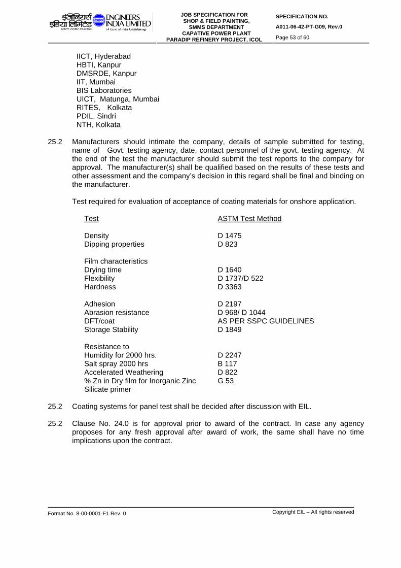
SPECIFICATION NO.
A011-06-42-PT-G09, Rev.0 JOB SPECIFICATION FOR
SHOP & FIELD PAINTING, SMMS DEPARTMENT
CAPATIVE POWER PLANT PARADIP REFINERY PROJECT, ICOL Page 53 of 60
Format No. 8-00-0001-F1 Rev. 0 Copyright EIL – All rights reserved
IICT, Hyderabad HBTI, Kanpur DMSRDE, Kanpur IIT, Mumbai BIS Laboratories UICT, Matunga, Mumbai RITES, Kolkata PDIL, Sindri NTH, Kolkata 25.2 Manufacturers should intimate the company, details of sample submitted for testing,
name of Govt. testing agency, date, contact personnel of the govt. testing agency. At the end of the test the manufacturer should submit the test reports to the company for approval. The manufacturer(s) shall be qualified based on the results of these tests and other assessment and the company’s decision in this regard shall be final and binding on the manufacturer.
Test required for evaluation of acceptance of coating materials for onshore application. Test ASTM Test Method Density D 1475 Dipping properties D 823 Film characteristics Drying time D 1640 Flexibility D 1737/D 522 Hardness D 3363 Adhesion D 2197 Abrasion resistance D 968/ D 1044 DFT/coat AS PER SSPC GUIDELINES Storage Stability D 1849 Resistance to Humidity for 2000 hrs. D 2247 Salt spray 2000 hrs B 117 Accelerated Weathering D 822 % Zn in Dry film for Inorganic Zinc G 53 Silicate primer 25.2 Coating systems for panel test shall be decided after discussion with EIL. 25.2 Clause No. 24.0 is for approval prior to award of the contract. In case any agency
proposes for any fresh approval after award of work, the same shall have no time implications upon the contract.

SPECIFICATION NO.
A011-06-42-PT-G09, Rev.0 JOB SPECIFICATION FOR
SHOP & FIELD PAINTING, SMMS DEPARTMENT
CAPATIVE POWER PLANT PARADIP REFINERY PROJECT, ICOL Page 54 of 60
Format No. 8-00-0001-F1 Rev. 0 Copyright EIL – All rights reserved
ANNEXURE-I
LIST OF RECOMMENDED MANUFACTURERS Indian Vendors 1. Asian Paints (I) Ltd., Mumbai 2. Berger paints Ltd., Kolkata 3. Kansai Nerolac Paints Ltd., Mumbai ( including Ameron, USA Products ). 4. Chugoku Marine Paints Pvt. Ltd., Mumbai 5. Shalimar Paints Ltd., Kolkata 6. Sigma Kalon Marine and Protective Coatings(India) Pvt Ltd, Mumbai. 7. CDC Carboline Ltd., Chennai 8. Premier products Ltd., Mumbai 9. Coromandel Paints & Chemicals Ltd., Visakhapatnam 10. Anupam Enterprises, Kolkata 11. Grand Polycoats, Vadodata 12. Bombay Paints Ltd., Mumbai 13. Akzo Nobel Coatings and Sealants Pvt. Ltd., Bangalore 14. Cipy Polyurethanes Pvt. Ltd., Pune 15. Gunjan Paints Ltd., Ahmedabad 16. Advance Paints Ltd., Mumbai 17. VCM Polyurethane Paints (for polyurethane paints only) 18. Jotun Paints India Pvt Ltd, Chennai(Singapore) 19. Paladin Paints and Chemicals , Mumbai 20. Chembond Chemicals Pvt Ltd , Navi Mumbai 21. Aashish Coating Technologies Pvt. Ltd, Vadodara/Mumbai Foreign Vendors 1. Sigma Kalon Protective Coatings, Singapore 2. Ameron, USA 3. Kansai Paints, Japan 4. Hempel Paints, USA 5. Valspar Corporation, USA 6. Akzo Nobel/International Coatings, UK 7. Jotun Paints, Singapore The following are approved for specific materials only. 1.0 Mark-chem Incorporated, Mumbai (for phosphating chemicals only). 2.0 ChemTreat India Ltd.( for Phosphating Chemical and glass flake filled coatings of M/s
Atlas Chemicals Corporation, USA). 3.0 Carolina equipment and supply Co., USA. 4.0 Zinga Metall(Rozenstraat 4-Industrial Zone)-9810 EKE-Belgium, Indian Agent-Newkem,
Mumbai-14 (for cold spray zinc coating)

SPECIFICATION NO.
A011-06-42-PT-G09, Rev.0 JOB SPECIFICATION FOR
SHOP & FIELD PAINTING, SMMS DEPARTMENT
CAPATIVE POWER PLANT PARADIP REFINERY PROJECT, ICOL Page 55 of 60
Format No. 8-00-0001-F1 Rev. 0 Copyright EIL – All rights reserved
ANNEXURE-II LIST OF RECOMMENDED MANUFACTURERS’ PRODUCTS
Sl. No
Manufacturers Name
P2 Chlorinated
Rubber Zinc Ph Primer
P4 Etch Primer/ Wash Primer
P6 Epoxy Zinc Ph. Primer
F9 Inorganic
Zinc Silicate Primer/ Coating
1 ASIAN PAINTS (I) LTD.
ASIOCHLOR HB.ZN.PH.PRIMER RO PC 168
APCONYL WP636 (PC335)
APCODUR HB.ZP. PC433
APCOSIL 605
2 BERGER PAINTS LTD.
LINOSOL HIGH BUILD ZP PRIMER
BISON WASH PRIMER
EPILUX 610 HB PRIMER
ZINC ANODE 304 MZS
3 AMERON PRODUCTS
- AMERCOAT 178 AMERCOAT 71/ 385P
DIMETCOTE-9FT
4 CHEMBOND CHEMICALS
KEMCHLOR 201 KEMGALVA GRIP A1
KEMOXY 301 KEMGUARD 501
5 SHALIMAR PAINTS LTD
CHLOROKOTE ZINC PHOSPHATE PRIMER GREY
TUFFKOTE ETCH PRIMER
EPIGUARD ZINC PHOSPHATE PRIMER GREY
TUFFKOTE ZILIKATE
6 SIGMA KALON INDIA PVT LTD,
SIGMA NUCOL UNICOAT 7321
SIGMA ETCH PRIMER (7185)
SIGMA COVER 256 (7412)
SIGMAZINC- 158
7 CDC CARBOLINE LTD.
- - CARBOLINE 893
CARBOZINC 11
8 PREMIER PRODUCTS LTD.
- - P-15/3A U-16/92
U17/92 ETHYL SILICATE INORGANIC ZINC
9 CORAMANDEL PAINTS & CHEMICALS LTD.
COROCLORE CR HB.ZN.PH PRIMER
CPC WASH PRIMER
COROPEX EPOXY ZN.PH. HIGH BILD PRIMER
CPC INORGANIC ZINC SILICATE PRIMER
10 ANUPAM ENTERPRISES
ANUCHLOR ZP PRIMER
ANUPRIME-291 ANUPAM ANLICOR A-EZP-500
ANUZINC 2001 TP
11 GRAND POLYCOATS
GP CHLOROPRIME 601
GP PRIME 401 - GP PRIME 402
12 BOMBAY PAINTS LTD.
PENTA CHLOR HB PRIMER 8632
PENTOLITE WASH PRIMER 8520
PENTADUR PRIMER 8530
ZINC-O-SIL 75
13 HEMPEL MARINE PAINTS
HEMPA TEX HIGHBUILD 4633
- HEMPEL’S SHOP PRIMER E1530
GALVASOL 1570
14 AASHISH COATING TECH-
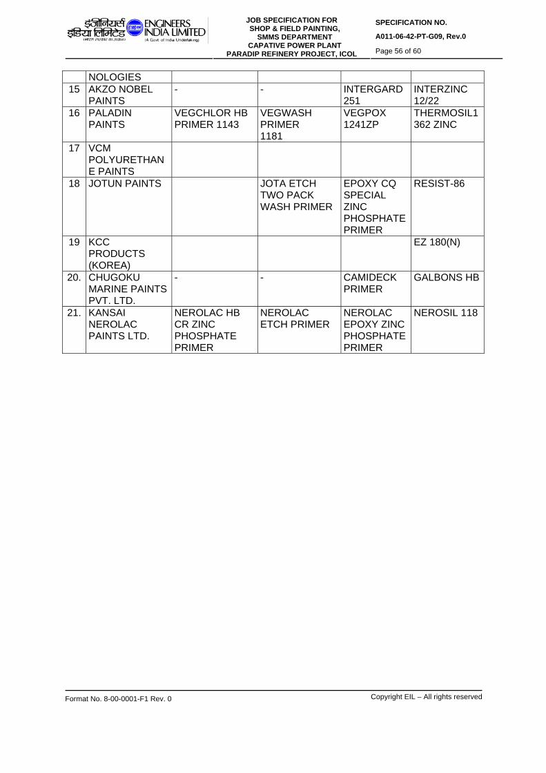
SPECIFICATION NO.
A011-06-42-PT-G09, Rev.0 JOB SPECIFICATION FOR
SHOP & FIELD PAINTING, SMMS DEPARTMENT
CAPATIVE POWER PLANT PARADIP REFINERY PROJECT, ICOL Page 56 of 60
Format No. 8-00-0001-F1 Rev. 0 Copyright EIL – All rights reserved
NOLOGIES 15 AKZO NOBEL
PAINTS - - INTERGARD
251 INTERZINC 12/22
16 PALADIN PAINTS
VEGCHLOR HB PRIMER 1143
VEGWASH PRIMER 1181
VEGPOX 1241ZP
THERMOSIL1362 ZINC
17 VCM POLYURETHANE PAINTS
18 JOTUN PAINTS JOTA ETCH TWO PACK WASH PRIMER
EPOXY CQ SPECIAL ZINC PHOSPHATE PRIMER
RESIST-86
19 KCC PRODUCTS (KOREA)
EZ 180(N)
20. CHUGOKU MARINE PAINTS PVT. LTD.
- - CAMIDECK PRIMER
GALBONS HB
21. KANSAI NEROLAC PAINTS LTD.
NEROLAC HB CR ZINC PHOSPHATE PRIMER
NEROLAC ETCH PRIMER
NEROLAC EPOXY ZINC PHOSPHATE PRIMER
NEROSIL 118

SPECIFICATION NO.
A011-06-42-PT-G09, Rev.0 JOB SPECIFICATION FOR
SHOP & FIELD PAINTING, SMMS DEPARTMENT
CAPATIVE POWER PLANT PARADIP REFINERY PROJECT, ICOL Page 57 of 60
Format No. 8-00-0001-F1 Rev. 0 Copyright EIL – All rights reserved
LIST OF RECOMMENDED MANUFACTURERS PRODUCTS (Cont. …) Sl. No
Manufacturers Name
F2 Acrylic-
Polyurethane Finish Paint
F3 Chlorinated
Rubber Finish Paint
F6A/B High Build
Epoxy Finish Paint
F7 High Build Coal
Tar Epoxy Coating
1 ASIAN PAINTS (I) LTD.
APCOTHANE CF676 (PC 1109)
ASIOCHLOR CF 621 (PC 319)
APCODUR HB COATING PC 1262
APCODUR CF 651/655(PC 131/471)
2 BERGER PAINTS LTD.
BERGER ACRYLIC PU FINISH
LINOSOL CHLORINATED RUBBER HB COATING
EPLIUX 04 AND 78 HB EPOXY COATING
EPILUX 555
3 AMERON
AMERCOAT 450GL
AMERCOAT 515 AMERCOAT 383 HS
AMERCOAT 78HB
4 CHEMBOND CHEMCIALS
KEMTHANE 411 KEMCHLOR 211 KEMOXY 324 KEMOXY 314
5 SHALIMAR PAINTS LTD
SHALITHANE FINISH
CHLORKOTE HB FINISH
EPIGARD TL FINISH POLYAMINE/ POLYAMIDE
BIPIGARD CTE ZL BLACK HB COAL TAR EPOXY COATING
6 SIGMA COATINGS.
SIGMADUR GLOSS (7528)
SIGMA NUCOL FINISH 7308
SIGMA GUARD 720
SIGMACOVER 300 (7472)
7 CDC CARBOLINE LTD.
CARBOLINE 132 - CARBOLINE 191
CARBO- MASTIC-14
8 PREMIER PRODUCTS LTD.
U3/92 POLYURETHANE
CR-71, CR FINISH PAINT
42B/4A HIGH BUILD EPOXY
350/3A, COAL TAR EPOXY COATING
9 CORAMANDEL PAINTS & CHEMICALS LTD.
COROTHANE SUPER PU FINISH
COROCLORE CR FINISHING
COROPEX EPOXY HB COATING
COROPEX EPOXY COAL TAR COATING
10 ANUPAM ENTERPRISES
ANUTHANE ENAMEL
ANUCHLOR HB ENAMEL
DURACOAT-6000
COROGUARD
11 GRAND POLYCOATS
GP BOND 141 GP CHLOROGAURD 631
GP GUARD HP234
POLYGUARD CE
12 BOMBAY PAINTS LTD.
PENTATHANE FP 4510
PENTACHLOR FB 4635
PENTADUR HB 5540/5520
PENTADUR COALTAR EPOXY 8518/6518
13. HEMPEL MARINE PAINTS
- HEMPATEX HIBUILD 4633
HEMPADUR HIGH BUILD 5520
HEMPADUR 1510
14. AASHISH COATING TECH
GA 1110 PU-UB GA701 HB
15 AKZO NOBEL COAITNGS
INTERTHANE 990 - INTERGARD 966 / 410
INTERTUF 262 (TAR FREE TYPE)

SPECIFICATION NO.
A011-06-42-PT-G09, Rev.0 JOB SPECIFICATION FOR
SHOP & FIELD PAINTING, SMMS DEPARTMENT
CAPATIVE POWER PLANT PARADIP REFINERY PROJECT, ICOL Page 58 of 60
Format No. 8-00-0001-F1 Rev. 0 Copyright EIL – All rights reserved
16 PALADIN PAINTS
VEGTHANE (ALIPHATIC)
VEGCHLOR FP3140
VEGEPOX 3245/3562
VEGEPOX 4265
17 VCM POLYURETHANE PAINTS
PIPCOTHANE ALIPHATIC POLYURETHANE FINISH PAINT
18 JOTUN PAINTS
HARDTOP XP PENGUARD HB
JOTAGUARD 85
19 KCC PRODUCTS (KOREA)
KOEPOX TOPCOAT HB ET 5740
EH 173
20. CHUKOGU MARINE PAINTS PVT LTD.
UNY MARINE - EPICON MARINE FINISH HB
BISCON HB 2001/ACHB
21. KANSAI NEROLAC PAINTS
NEROTHANE ENAMEL
NEROLAC HB CHLORINATED RUBBER ENAMEL
NEROPOXY HB 262/6061
NEROLAC EPOXY COAL TAR POLYAMINE/POLYAMIDE CURED.

SPECIFICATION NO.
A011-06-42-PT-G09, Rev.0 JOB SPECIFICATION FOR
SHOP & FIELD PAINTING, SMMS DEPARTMENT
CAPATIVE POWER PLANT PARADIP REFINERY PROJECT, ICOL Page 59 of 60
Format No. 8-00-0001-F1 Rev. 0 Copyright EIL – All rights reserved
LIST OF RECOMMENDED MANUFACTURERS PRODUCTS (cont. …) Sl. No.
Manufacturers Name
F8 Epoxy Mastic
Coating Surface Tolerant
F-11 Heat Resistant
Synthetic Medium
Aluminium Paint
F-12 Heat Resistant
Silicone Aluminium
Paint
F-15 Two Pack Ambient
Temperature Curing Epoxy
Phenolic Coating
1 ASIAN PAINTS (I) LTD.
APCODOR CF 640
ASIAN HR ALUMINIUM PAINT (PC 300)
HR SILICONE ALUMINIUM PAINT (PC 189)
2 BERGER PAINTS LTD.
PROTECTO MASTIC
FERROTOL HR ALUMINIUM PAINT
LUMEROS HR SILICONE AL. PAINT(HR/143)
BERGER EPOXY PHENOLIC COATING
3 AMERON
AMERLOCK 400 AMERCOAT 878
4 CHEMBOND CHEMICALS
KEMGUARD 555 KEMGUARD 250HR
- -
5 SHALIMAR PAINTS LTD
EPIPLUS 556 HEAT RESISTING LUSTROL ALUMINIUM
LUSTOTHERM HS SILICONE ALUMINIUM
EPIGARD TL 543 HS FINISH
6 SIGMA COATINGS.
SIGMA COVER 630 (7428)
HIGH TEMPERATURE RESISTANT EPOXY SYSTEM UPTO 200OC
SIGMATHERM 540/SUPER THERMOVIT 600
SIGMA PHENGUARD 930 SYSTEM
7 CDC CARBOLINE LTD.
CARBO MASTIC-15
CARBOLINE 1248
CARBOLINE 4674
8 PREMIER PRODUCTS LTD.
BH EPOXY MASTIC 150B/150A
9 CORAMANDEL PAINTS & CHEMICALS LTD.
- SILVOTOL HR ALUMINIUM PAINT
CPC SILICONE HR ALUMINIUM PAINT
10 ANUPAM ENTERPRISES
ANU- MASTIC-102
- ANUPAM HEAT GUARD.
11 GRAND POLYCOATS
GP PRIME GUARD 235
- -
12 BOMBAY PAINTS LTD.
PENTADUR MASTIC 5515
KANGAROO HHR ALUMINIUM 4950
PENTHOLITE HRR ALUMINIUM 4951
13. HEMPEL MARINE PAINTS
HEMPDUR 1708
14 AASHISH COATING TECH
GA700SPE - - -

SPECIFICATION NO.
A011-06-42-PT-G09, Rev.0 JOB SPECIFICATION FOR
SHOP & FIELD PAINTING, SMMS DEPARTMENT
CAPATIVE POWER PLANT PARADIP REFINERY PROJECT, ICOL Page 60 of 60
Format No. 8-00-0001-F1 Rev. 0 Copyright EIL – All rights reserved
15 AKZO NOBEL COATINGS
INTERSEAL 670HS
INTERTHERM 891
INTERTHERM 50
INTERTHERM 228
16 PALADIN PAINTS
VEGEPOX MASTIC 2285
VEG HR AL PAINT
VEG HHR AL PAINT 600 DEG C
17 VCM POLYURETHANE PAINTS
- - - -
18 JOTUN PAINTS PRIMASTIC UNIVERSAL
JOTUN AL PAINT HR 250 DEG.C
SOLVELITT AL SILICONE PAINT
TANKGUARD STORAGE
19 KCC PRODUCTS (KOREA)
EH 4158H QT 606
20. CHUKOGU J&N LTD.
UMEGUARD MT/SX
21. KANSAI NEROLAC PAINTS LTD.
NEROMASTIC 400
NEROTHERM 250
NEROTHERM 538
Note : This list is subject to revision based on fresh approval/ re-approval/ deletion.

VOLUME- IA PART–III CHAPTER 1
Form No: F-A (Rev 00)
BACKUP GUARANTEE AGREEMENT (To be executed on Rs.100/- non–judicial stamp paper)
THIS AGREEMENT is made and executed on this _______ day of _______, between
M/s _____________________(the First Party, i.e, the Bidder) a company incorporated
under the Company's Act 1956, having its registered office at
________________________(hereinafter called the "Bidder", which expression shall
include its successors, administrators, executors and permitted assigns) and
(2) M/s ________________________, (the Second Party, i.e, the Backup Guarantor), a
company incorporated under the Company's Act 1956, having its registered office at
________________________ (hereinafter called the “Backup Guarantor", which
expression shall include its successors, administrators, executors and permitted assigns).
WHEAEAS the owner, M/s.Bharat Heavy Electricals Ltd, a Government of India
undertaking, proposes to issue / issued an NIT (hereinafter referred to as the said NIT)
inviting bids from the individual bidders for undertaking the work of __________________
____________, at ______________________ (hereinafter referred to as the said works).
WHEREAS the said NIT enables submission of a bid with a Backup Guarantee subject to
fulfillment of the Qualification criteria and other tender conditions specified in the said NIT.
AND WHEREAS M/s _____________________________ (The First Party, i.e, the
Bidder) will submit its proposal in response to the aforesaid invitation to bid by the
Owner for ______________________________________________ (as detailed in the
Bid doc. no. < TENDER REF--------> )
AND WHEREAS M/s _______________________ (The First Party, i.e the Bidder) itself is
meeting the qualifying requirements of financial criteria
____________________________________________ (as detailed in the NIT) and in
order to fully meet the qualifying requirements of technical in NIT, this back-up agreement
is being entered into with M/s __________________________ (The Second Party, the
Associates) , who fully meet the balance part of the said works
(_____________________________).
Page 1 of 3

TECHNICAL CONDITIONS OF CONTRACT (TCC)
Technical Conditions of Contract (Document no PS:MSC:TCC, Rev 00, 6th July 2010)
WHEREAS the First Party and the Second Party are contractors engaged in the
business of carrying out similar/various items of works. WHEREAS the two parties
have agreed to constitute themselves into a backup guarantee agreement for the
purpose of carrying out the said works, and that the Backup Guarantee will be
continued till the completion of the works in all respects. The backup guarantor will
undertake and complete the work in case the bidder fails to execute the subject
work with the same terms and conditions of the subject tender.
WHEREAS the parties have agreed to certain terms and conditions in this regard:
NOW THEREFORE THIS AGREEMENT WITNESSETH AS FOLLOWS :
1. First and Second parties hereby constitute themselves into a Backup Guarantee for the purpose of bidding and undertaking the said works pursuant to the said NIT as hereinafter stated.
2. The First Party will be the Lead bidder and will be responsible for the entire works.
BACKUP GUARANTEE AGREEMENT
3. The First Party shall undertake the following part(s) of work detailed in the NIT namely ______________________________________________________________
4. The Second Party shall undertake to provide a backup guarantee to ensure smooth & proper completion of the following part(s) of work detailed in the said NIT namely _________________________________________________________________
5. The parties hereby declare and confirm that each of them will fulfill the required minimum qualifying requirements as prescribed in the said NIT for the works agreed to be undertaken by them as stated here-in-above.
6. It is also agreed between the parties hereto that all of them shall be severally and jointly responsible for the completion of the said works as per the schedule. Further, if the Employer/Owner sustains any loss or damage on account of any breach of the contract(s), we(First party & Backup guarantor), severally and jointly undertake to promptly indemnify and pay such losses / damages caused to the Employer/Owner on their written demand without any demur, reservation, contest or protest in any manner whatsoever.
Page 2 of 3

TECHNICAL CONDITIONS OF CONTRACT (TCC)
Technical Conditions of Contract (Document no PS:MSC:TCC, Rev 00, 6th July 2010)
7. The parties hereby agree and undertake that they shall provide adequate finances, suitable tools, plants, tractors, trailers, other transportation equipment, other tools & plants, measuring & monitoring equipments (MMEs), men and machinery etc. for the proper and effective execution of the works to be undertaken by them as specified here-in-above.
8. It is agreed between the parties hereto that all the consequences, liabilities etc., arising out of any default in the due execution of the said works shall be borne by the party in default, that is by the party in whose area of work the default has occurred, provided however, so far as M/s Bharat Heavy Electricals Limited is concerned, all the parties shall be liable severally and jointly.
9. The backup guarantor hereby ensures that they have submitted a BG equivalent to 10% of the bid amount in the prescribed format, valid for the duration of the tendered works in a SEALED cover superscribed as“BG from Back up guarantor” along with price bid (Volume II). A declaration certificate in his letter head to this effect is submitted by him to BHEL, duly signed along with the Techno Commercial bid.
IN WITNESS HEREOF the parties above named have signed this agreement on the
day month and year first above written at __________(Place) .
WITNESS For (FIRST PARTY)
1. NAME
2. OFFICIAL ADDRESS
WITNESS For (SECOND PARTY)
1. NAME
2. OFFICIAL ADDRESS
[The successful bidder shall have to execute the "JOINT DEED OF UNDERTAKING” in
the format to be made available by BHEL at the time of submission of tender].
Page 3 of 3

TECHNICAL CONDITIONS OF CONTRACT (TCC)
Technical Conditions of Contract (Document no PS:MSC:TCC, Rev 00, 6th July 2010)
VOLUME- IA PART–III CHAPTER 2
DECLARATION
BACKUP GUARANTOR DECLARATION
(THIS DECLARATION CERTIFICATE IN HIS LETTER HEAD WITH DULY SIGNED AND
ENCLOSED IN THE BIDDER’S TECHNICAL OFFER).
I / WE_____________________(BACKUP GUARANTOR) DECLARES THAT A BANK
GUARANTEE BEARING NO:_______________________________,DT:__________
FOR 10% OF THE BID AMOUNT TOWARDS______________________________VALID
UPTO______________FROM_______________(BANK) IS ENCLOSED WITH PRICE
BID (VOLUME II).WE CONFIRM THAT WE HAVE PROVIDED BACKUP GUARANTEE
FOR THIS TENDER IN THIS PROJECT TO ANY OTHER BIDDER.
FOR AND BEHALF OF M/S___________
(SIGNATURE WITH OFFICIAL SEAL)
Note: The tender will be liable to be rejected if the requisite BG is found to be not
enclosed in the Price bid by the bidder.

TECHNICAL CONDITIONS OF CONTRACT (TCC)
Technical Conditions of Contract (Document no PS:MSC:TCC, Rev 00, 6th July 2010)
BIDDER’S DECLARATION
(THIS DECLARATION CERTIFICATE IN HIS LETTER HEAD WITH DULY SIGNED AND
ENCLOSED IN THE BIDDER’S TECHNICAL OFFER).
I / WE ___________________________________________________________
DECLARE THAT WE GONE THROUGH THE TENDER CONDITIONS AND
ACCORDINGLY WE SELECTED THE BACKUP GUARANTOR
M/S___________________________________________________________________
WHO IS FULFILLING THE STIPULATED QUALIFICATION REQUIREMENT IN THE
TENDER AND WHOSE QUALIFYING EXPERIENCE DOCUMENTS ARE ENCLOSED IN
OUR OFFER.
FOR AND BEHALF OF M/S___________
(SIGNATURE WITH OFFICIAL SEAL)
Note: The tender will be liable to be disqualified if the required documents of the
backup Guarantor is found to be not enclosed in the offer.


