13D A2012 ROC ballot - NFPA€¦ · the shadow area concept has been added to the standard to...
59
National Fire Protection Association 1 Batterymarch Park, Quincy, MA 02169-7471 Phone: 617-770-3000 • Fax: 617-770-0700 • www.nfpa.org M E M O R A N D U M TO: NFPA Technical Committee on Residential Sprinkler Systems FROM: Elena Carroll, Administrator, Technical Projects DATE: October 11, 2011 SUBJECT: NFPA 13D ROC TC Letter Ballot (A2012) ______________________________________________________________________ The ROC letter ballot for NFPA 13D is attached. The ballot is for formally voting on whether or not you concur with the committee’s actions on the comments. Reasons must accompany all negative and abstention ballots. Please do not vote negatively because of editorial errors. However, please bring such errors to my attention for action. Please complete and return your ballot as soon as possible but no later than Tuesday, November 1, 2011 . As noted on the ballot form, please return the ballot to Elena Carroll either via e-mail to [email protected] or via fax to 617-984-7110. You may also mail your ballot to the attention of Elena Carroll at NFPA, 1 Batterymarch Park, Quincy, MA 02169. The return of ballots is required by the Regulations Governing Committee Projects. Attachments: Comments Letter Ballot
Transcript of 13D A2012 ROC ballot - NFPA€¦ · the shadow area concept has been added to the standard to...

National Fire Protection Association 1 Batterymarch Park, Quincy, MA 02169-7471 Phone: 617-770-3000 • Fax: 617-770-0700 • www.nfpa.org
M E M O R A N D U M TO: NFPA Technical Committee on Residential Sprinkler Systems FROM: Elena Carroll, Administrator, Technical Projects DATE: October 11, 2011 SUBJECT: NFPA 13D ROC TC Letter Ballot (A2012)
______________________________________________________________________ The ROC letter ballot for NFPA 13D is attached. The ballot is for formally voting on whether or not you concur with the committee’s actions on the comments. Reasons must accompany all negative and abstention ballots. Please do not vote negatively because of editorial errors. However, please bring such errors to my attention for action. Please complete and return your ballot as soon as possible but no later than Tuesday, November 1, 2011. As noted on the ballot form, please return the ballot to Elena Carroll either via e-mail to [email protected] or via fax to 617-984-7110. You may also mail your ballot to the attention of Elena Carroll at NFPA, 1 Batterymarch Park, Quincy, MA 02169. The return of ballots is required by the Regulations Governing Committee Projects. Attachments:
Comments Letter Ballot
Report on Comments – June 2012 NFPA 13D_______________________________________________________________________________________________13D-1 Log #CC1 AUT-RSS
_______________________________________________________________________________________________Technical Committee on Residential Sprinkler Systems,
13D-18Add new language to the "Scope" section of NFPA 13D as follows:
- This standard does not provide requirements for the design or installation of water mist fire protection systems,which are not considered fire sprinkler systems and are addressed by NFPA 750, The Standard on Water Mist FireProtection Systems.
Various TC's addressed multiple proposals addressing the inclusion of water mist systems in NFPA 13.Water Mist systems are covered in NFPA 750 and the NFPA 750 TC has the committee scope to write requirementsdealing with these systems. Rather than writing a definition of sprinkler that more clearly addresses the committee'sintent that mist system/equipment are not covered in the standard, the TC felt it was more direct to cover this topic in thedocument scope.
_______________________________________________________________________________________________13D-2 Log #68 AUT-RSS
_______________________________________________________________________________________________Peter T. Schwab, Wayne Automatic Fire Sprinklers, Inc.
13D-9Accept the original proposal as submitted.
Brass pipe is a viable option to copper and steel. The design burst pressure for standard weight pipeto the maximum system pressure of 175 psig is a factor of at least 2.7 for sizes 6 in. and smaller. The design burstpressure for Extra Strong Weight pipe to the maximum system pressure of 300 psig is a factor of at least 5 for sizes 8 in.and smaller. Both the standard and the extra strong weights exceed to factors for copper pipe in the permissiblethicknesses.
_______________________________________________________________________________________________13D-3 Log #CC2 AUT-RSS
_______________________________________________________________________________________________Technical Committee on Residential Sprinkler Systems,
13D-10Revise as follows:
Antifreeze Sprinkler System. A wet pipe system using automatic sprinklers that contains a liquid solution toprevent freezing of the system, intended to discharge the solution upon sprinkler operation, followed immediately bywater from a water supply.
Update the definition of antifreeze sprinkler system to be consistent with the definition accepted byNFPA 13 (SSI TC)
1Printed on 10/11/2011
Report on Comments – June 2012 NFPA 13D_______________________________________________________________________________________________13D-4 Log #26 AUT-RSS
_______________________________________________________________________________________________Technical Correlating Committee on Automatic Sprinkler Systems,
13D-1aWhere and when the TC's use the term "Readily Accessible", the TC's are directed to better define
their intent on a case by case basis.This is a direction from the Technical Correlating Committee on Automatic Sprinkler Systems in
accordance with 3.4.2 and 3.4.3 of the Regulations Governing Committee Projects.
Task Group reviewed and the Term “Readily Accessible” is not used in NFPA 13D.
2Printed on 10/11/2011
Report on Comments – June 2012 NFPA 13D_______________________________________________________________________________________________13D-5 Log #56 AUT-RSS
_______________________________________________________________________________________________Kenneth E. Isman, National Fire Sprinkler Association, Inc.
13D-70Insert a definition for Shadow Area and an annex note as follows:
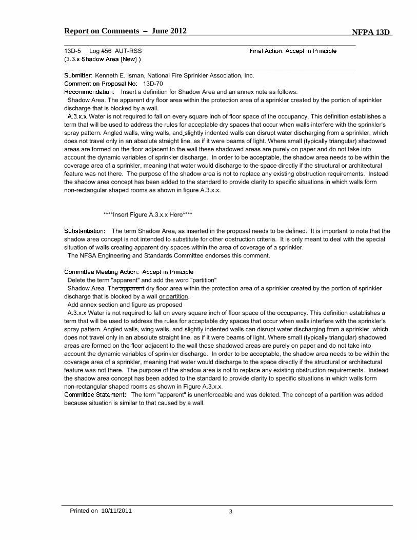
Shadow Area. The apparent dry floor area within the protection area of a sprinkler created by the portion of sprinklerdischarge that is blocked by a wall.
Water is not required to fall on every square inch of floor space of the occupancy. This definition establishes aterm that will be used to address the rules for acceptable dry spaces that occur when walls interfere with the sprinkler’sspray pattern. Angled walls, wing walls, and slightly indented walls can disrupt water discharging from a sprinkler, whichdoes not travel only in an absolute straight line, as if it were beams of light. Where small (typically triangular) shadowedareas are formed on the floor adjacent to the wall these shadowed areas are purely on paper and do not take intoaccount the dynamic variables of sprinkler discharge. In order to be acceptable, the shadow area needs to be within thecoverage area of a sprinkler, meaning that water would discharge to the space directly if the structural or architecturalfeature was not there. The purpose of the shadow area is not to replace any existing obstruction requirements. Insteadthe shadow area concept has been added to the standard to provide clarity to specific situations in which walls formnon-rectangular shaped rooms as shown in figure A.3.x.x.
****Insert Figure A.3.x.x Here****
The term Shadow Area, as inserted in the proposal needs to be defined. It is important to note that theshadow area concept is not intended to substitute for other obstruction criteria. It is only meant to deal with the specialsituation of walls creating apparent dry spaces within the area of coverage of a sprinkler.The NFSA Engineering and Standards Committee endorses this comment.
Delete the term "apparent" and add the word "partition"Shadow Area. The apparent dry floor area within the protection area of a sprinkler created by the portion of sprinkler
discharge that is blocked by a wall or partition.Add annex section and figure as proposedA.3.x.x Water is not required to fall on every square inch of floor space of the occupancy. This definition establishes a
term that will be used to address the rules for acceptable dry spaces that occur when walls interfere with the sprinkler’sspray pattern. Angled walls, wing walls, and slightly indented walls can disrupt water discharging from a sprinkler, whichdoes not travel only in an absolute straight line, as if it were beams of light. Where small (typically triangular) shadowedareas are formed on the floor adjacent to the wall these shadowed areas are purely on paper and do not take intoaccount the dynamic variables of sprinkler discharge. In order to be acceptable, the shadow area needs to be within thecoverage area of a sprinkler, meaning that water would discharge to the space directly if the structural or architecturalfeature was not there. The purpose of the shadow area is not to replace any existing obstruction requirements. Insteadthe shadow area concept has been added to the standard to provide clarity to specific situations in which walls formnon-rectangular shaped rooms as shown in Figure A.3.x.x.
The term "apparent" is unenforceable and was deleted. The concept of a partition was addedbecause situation is similar to that caused by a wall.
3Printed on 10/11/2011

Report on Comments – June 2012 NFPA 13D_______________________________________________________________________________________________13D-6 Log #40 AUT-RSS
_______________________________________________________________________________________________Kenneth E. Isman, National Fire Sprinkler Association
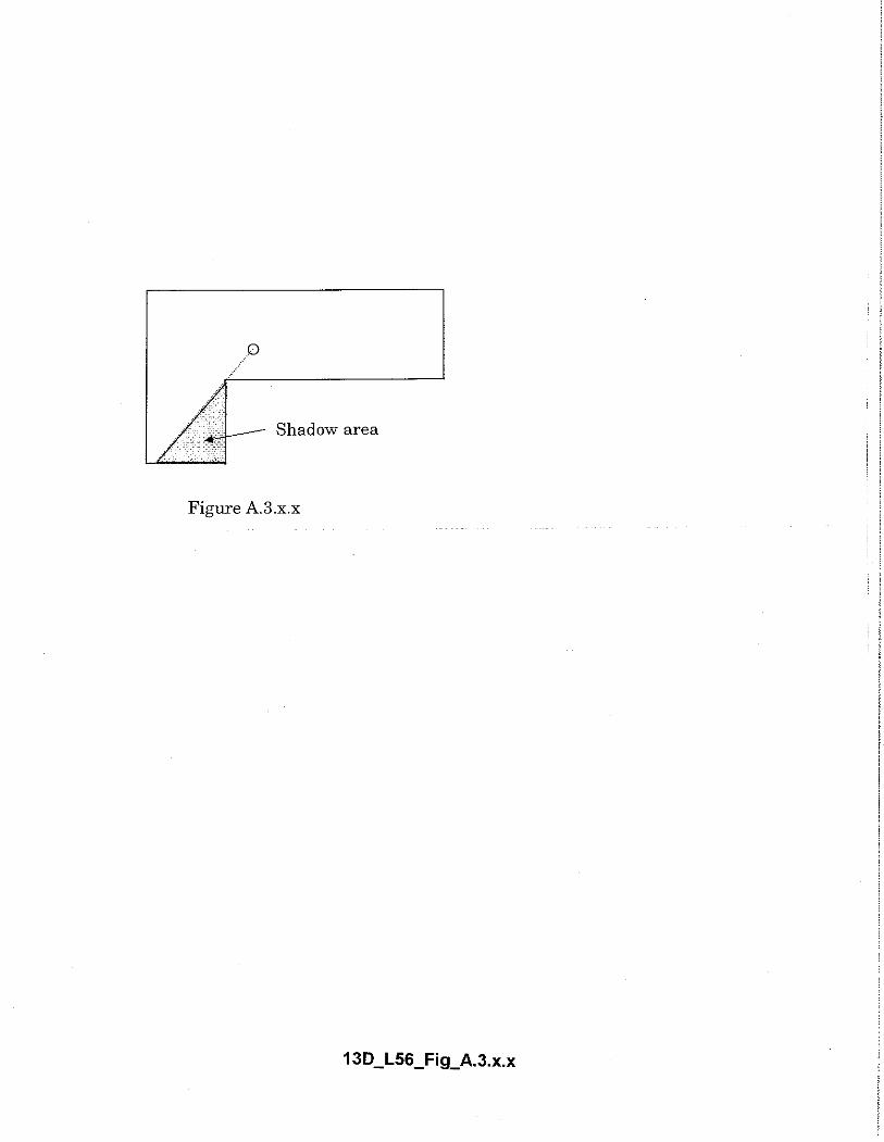
13D-70Insert a definition for Shadow Area and an annex note as follows:
Shadow Area. The apparent dry floor area within the protection area of a sprinkler created by the portion of sprinklerdischarge that is blocked by a wall.
Water is not required to fall on every square inch of floor space of the occupancy. This definition establishes aterm that will be used to address the rules for acceptable dry spaces that occur when walls interfere with the sprinkler’sspray pattern. Angled walls, wing walls, and slightly indented walls can disrupt water discharging from a sprinkler, whichdoes not travel only in an absolute straight line, as if it were beams of light. Where small (typically triangular) shadowedareas are formed on the floor adjacent to the wall these shadowed areas are purely on paper and do not take intoaccount the dynamic variables of sprinkler discharge. In order to be acceptable, the shadow area needs to be within thecoverage area of a sprinkler, meaning that water would discharge to the space directly if the structural or architecturalfeature was not there. The purpose of the shadow area is not to replace any existing obstruction requirements. Insteadthe shadow area concept has been added to the standard to provide clarity to specific situations in which walls formnon-rectangular shaped rooms as shown in figure A.3.x.x.
***INSERT ARTWORK HERE (FIGURE A.3.x.x)***
The term Shadow Area, as inserted in the proposal needs to be defined. It is important to note that theshadow area concept is not intended to substitute for other obstruction criteria. It is only meant to deal with the specialsituation of walls creating apparent dry spaces within the area of coverage of a sprinkler.The NFSA Engineering and Standards Committee endorses this comment.
See TC action on 13D-5 (Log #56)
_______________________________________________________________________________________________13D-7 Log #23 AUT-RSS
_______________________________________________________________________________________________Steven Orlowski, National Association of Home Builders
13D-11Continue with the technical committee's position of "reject" for proposal 13D-11.
See reasons stated in the NAHB ROP Ballot Comment.
4Printed on 10/11/2011
13D/L40/A2012/ROC/R
Shadow area
Figure A.3.x.x
Report on Comments – June 2012 NFPA 13D_______________________________________________________________________________________________13D-8 Log #69 AUT-RSS
_______________________________________________________________________________________________Dana R. Haagensen, Massachusetts Department of Fire Services
13D-11Accept Proposal 13D-11.
The Committee Statement does not address the submitter’s concern. The Committee Statementprovides no sound technical substantiation for the drastic change in the document’s scope for the 2007 edition. Suchsubstantiation has never been provided.To the contrary, the submitter of Proposal 13D-11 has provided sound technical substantiation for why the change was
invalid. Furthermore, in practice (and outside the “ivory tower” of the building code committees), the fire problem in atownhouse structure is drastically different for responding fire departments and occupants than with detachedsingle-family homes – particularly if the fire originates or extends to the attic area. In such circumstances, the issue is alife safety issue. For fire department operations at the scene of an attic fire in a detached single-family home at night,the department can do a quick search of the home for occupants with minimal crews and immediately move into adefensive fire attack from the exterior. With a townhouse structure, especially given an unlimited length of suchstructures, it becomes extremely labor-intensive to perform searches and make sure occupants of all the units areevacuated. In the real world, there are many residential fires where occupants of the building do not evacuate thinking itis another false alarm. In one situation, I found an occupant of a building, in the middle of a fire, that was watching thenews coverage of the fire on her TV.Also in the real world, the type of fire separations allowed by building codes for units to be considered “separate”dwellings does not contain attic fires to a single side of the separation as intended. There have been several real worldfires that demonstrate this concern. For examples, but not limited to: 1/3/2007 Georgetown MA (LongView - constructedin 2004); 2/22/2007 Raleigh NC - multiple townhouse structures simultaneously (Pine Knoll Townes - constructed in2006); 5/29/2008 Peabody MA (Highlands - constructed in 2006).
Accepting this requirement would create a conflict with the model building and residentialcodes. The TC does intend for NFPA 13D to be an option for all 1 and 2 family dwellings.
5Printed on 10/11/2011
Report on Comments – June 2012 NFPA 13D_______________________________________________________________________________________________13D-9 Log #48 AUT-RSS
_______________________________________________________________________________________________Milosh T. Puchovsky, Worcester Polytechnic Institute
13D-18Revise text to read as follows:
. A listed fire protection device through which water or water combined with an additive isdischarged in the form of droplets of varying sizes in a predetermined pattern so as to cover and reach a specified floorarea with the intent of suppressing or controlling a fire located below, and which is evaluated for such performancethrough standardized test methods. Water droplets discharged are of sufficient size to penetrate the fire plume, cool thecombustion zone, pre-wet adjacent combustibles and surfaces, and reduce ceiling temperatures.
A fire suppression or control device that operates automatically when itsheat-actuated element is heated to its thermal rating or above, allowing water to discharge over a specific area. Asprinkler that operates automatically when its heat-activated element is heated to its thermal rating or above.
A type of fast-response sprinkler having a thermal element with an RTI of 50(metersseconds) 1/2 or less, that has been specifically investigated for its ability to enhance survivability in the room offire origin, and that is listed for use in the protection of dwelling units.3.3.8.1.4 A sprinkler that does not have a cap or heat-activated element to control water discharge.
Water droplets produced by a sprinkler typically range in size from 200 microns to 1800 microns. See“Measurement of Droplet Size in Sprinkler Sprays” by J.R. Lawson, W.D. Walton, and D.D. Evans, NIST, February 1988(NBSIR 88-3715). While sprinkler devices are designed and manufactured to discharge a certain amount of water in acertain pattern over a predetermined floor area, individual design and installation standards address the use ofsprinklers in specific fire protection systems for specific applications. For example, NFPA 15,
permits the use of sprinklers as a means of exposure protection of vertical surfaces such as those ontransformers and storage tanks.
NFPA 13 does not include a definition for the term sprinkler. The proposed language describes how asprinkler is intended to perform and function, and aims to more clearly differentiate a sprinkler from other types ofdevices that can be used as part of a water-based fire protection system.The proposed language in this comment was created by an intercommittee task group consisting of members of the
RSS, SSI and NFPA 25 TC’s. This task group was created at the request of the TCC. While the majority of the taskgroup members agreed with the proposed language, there was a minority position that preferred not to include annextext in regard to NFPA 15.
This comment was rejected to correlate to the TC work done by SSI and 13R.
6Printed on 10/11/2011

Report on Comments – June 2012 NFPA 13D_______________________________________________________________________________________________13D-10 Log #20 AUT-RSS
_______________________________________________________________________________________________Technical Correlating Committee on Automatic Sprinkler Systems,
13D-12The TCC directs the RSS TC to modify the material property tables for antifreeze solutions
included in LOG #CP3 to use a temperature of 77°F when calculating the specific gravity of solutions.The TCC also directs the TC to review the need to specify the purity of antifreeze solutions, since field mixing is no
longer permitted.This is a direction from the Technical Correlating Committee on Automatic Sprinkler Systems in
accordance with 3.4.2 and 3.4.3 of the Regulations Governing Committee Projects.
Copy Table A.7.6.2.1 from NFPA 13 ROP and add to NFPA 13D A.8.3.3.1.2.
This table was deleted by the SSI TC during the ROC meeting. The table being pulled into 13D is based on the table atthe ROP meeting.
The TC reviewed the table at the request of the TCC and has included this information into theannex.
_______________________________________________________________________________________________13D-11 Log #46 AUT-RSS
_______________________________________________________________________________________________Marcelo M. Hirschler, GBH International
13D-10Revise text to read as follows:
Antifreeze Sprinkler System. A wet pipe sprinkler system employing automatic sprinklers that are attached toa piping system that contains an antifreeze solution and that are connected to a water supply. The antifreeze solution isdischarged, followed by water, immediately upon operation of sprinklers opened by heat from a fire.A.3.3.9.1 The antifreeze solution is discharged, followed by water, immediately upon operation of sprinklers opened by
heat from a fire.The solution offered by the technical committee does not resolve the problem of uniformity of
definitions but creates another definition. There are at present three almost identical definitions: NFPA 13, NFPA 13Dand NFPA 25. The only difference between the definitions is that the one in NFPA 13D omits the word “piping”.The technical committee responsible for NFPA 13 created a new definition that is different from the existing ones andnow there is a lack of uniformity.It is a much preferable outcome for the technical committee responsible for NFPA 13D to accept the proposal by the
Glossary committee and to choose a location for the second sentence, either the annex or a place in the standard (forexample within chapter 8). Note that the exact term is, in fact, not used in the standard.I am the chair of the Glossary Committee on Terminology.
It is the intent of the Committee that water immediately following the antifreeze solution definesan antifreeze system. NFPA 13 and 13 R need to correlate.
7Printed on 10/11/2011
Report on Comments – June 2012 NFPA 13D_______________________________________________________________________________________________13D-12 Log #47 AUT-RSS
_______________________________________________________________________________________________Milosh T. Puchovsky, Worcester Polytechnic Institute
13D-12Revise text to read as follows:
A mixture of an antifreeze material with water that is prepared andfactory-mixed by the manufacturer with a quality control procedure in place that ensures that the antifreeze solutionremains homogeneous and that the concentration is as specified.
The definitions for Premixed Anti freeze Solution put forth in the TIA’s for NFPA 13,13D and 25 allvaried slightly. The proposed language has been provided to create a single definition for pre-mixed Antifreeze Solutionin NFPA 13, 13D and 25.The proposed language in this comment was created by an intercommittee task group consisting of members of the
RSS, SSI and NFPA 25 TC’s. This task group was created at the request of the TCC.
_______________________________________________________________________________________________13D-13 Log #8 AUT-RSS
_______________________________________________________________________________________________Peter T. Schwab, Wayne Automatic Fire Sprinklers, Inc
13D-15Delete the following text:
A piping system intended to serve both domestic and fire protection needs from a common one piping systemthroughout the dwelling unit(s).
In the ROP meeting, the committee struck the word “one” from the proposal.
See action on 13D-14 (Log #36).
_______________________________________________________________________________________________13D-14 Log #36 AUT-RSS
_______________________________________________________________________________________________Kenneth E. Isman, National Fire Sprinkler Association
13D-15Revise text to read as follows:
Multipurpose Piping System. A piping system intended to serve both domestic needs in excess of a singlefixture and fire protection needs from a one common one piping system throughout the dwelling unit(s).
First, the grammar needed to be fixed. The phrase “from a common one piping system” was awkward.It appears better to say, “from one common piping system.”Second, there were negative ballots on Proposal 13D-24 due to a perceived conflict with Proposal 13D-15. While we
do not see there is a conflict, in order to help those that feel that some separation between Passive Purge Systems andMulti-Purpose systems is advantageous, the Multi-Purpose systems can be defined as those that serve more than asingle fixture, which eliminates even the hint of conflict.This comment has the endorsement of the NFSA Engineering and Standards Committee.
8Printed on 10/11/2011

Report on Comments – June 2012 NFPA 13D_______________________________________________________________________________________________13D-15 Log #52 AUT-RSS
_______________________________________________________________________________________________Kenneth E. Isman, National Fire Sprinkler Association, Inc.
13D-15Revise text to read as follows:
Multipurpose Piping System. A piping system intended to serve both domestic needs in excess of a singlefixture and fire protection needs from a one common one piping system throughout the dwelling unit(s).
First, the grammar needed to be fixed. The phrase “from a common one piping system” was awkward.It appears better to say, “from one common piping system.”Second, there were negative ballots on Proposal 13D-24 due to a perceived conflict with Proposal 13D-15. While we
do not see there is a conflict, in order to help those that feel that some separation between Passive Purge Systems andMulti-Purpose systems is advantageous, the Multi-Purpose systems can be defined as those that serve more than asingle fixture, which eliminates even the hint of conflict.This comment has the endorsement of the NFSA Engineering and Standards Committee.
_______________________________________________________________________________________________13D-16 Log #31 AUT-RSS
_______________________________________________________________________________________________Terry L. Victor, Tyco/SimplexGrinnell
13D-16Revise text to read as follows:
Accept in Principle proposal 13D-16 (Log #72) with the following changes:Replace “domestic plumbing fixture” with “toilet” as it is in the current edition:3.3.9.9 Passive Purge System. A type of stand-alone sprinkler system that serves a single domestic plumbing fixture
toilet in addition to the fire sprinklers.By allowing a single domestic plumbing fixture on a passive purge system, the intent to make sure
water is circulated through the system is compromised. If a hose bib is used as the single domestic fixture, the water inthe system could sit for weeks, months, or even years without being discharged or circulated. The most frequently useddomestic fixture is a toilet and this is what should be required on this system. In some states, it is further specified that itshould be the one in the master bath. This comment is being submitted by the Tyco Codes and Standards SprinklerTask Group.
The phrase "toilet" should be underlined (editorial) in the comment.
_______________________________________________________________________________________________13D-17 Log #34 AUT-RSS
_______________________________________________________________________________________________Kenneth E. Isman, National Fire Sprinkler Association
13D-16Revise text to read as follows:
In the definition of “Passive Purge” change “domestic plumbing fixture” back to “toilet”.The Passive Purge system was developed by water utilities that want to avoid the requirement for a
backflow device by creating some circulation through the sprinkler system through a fixture that is not used for drinkingwater. While we have no concern about the quality of water in a fire sprinkler system, in order to make this conceptpalatable to the water utilities, the fixture should be one that people will not drink out of.This comment has the endorsement of the NFSA Engineering and Standards Committee.
See TC action on 13D-16 (Log #31).
9Printed on 10/11/2011
Report on Comments – June 2012 NFPA 13D_______________________________________________________________________________________________13D-18 Log #50 AUT-RSS
_______________________________________________________________________________________________Kenneth E. Isman, National Fire Sprinkler Association, Inc.
13D-16In the definition of “Passive Purge” change “domestic plumbing fixture” back to “toilet”.
The Passive Purge system was developed by water utilities that want to avoid the requirement for abackflow device by creating some circulation through the sprinkler system through a fixture that is not used for drinkingwater. While we have no concern about the quality of water in a fire sprinkler system, in order to make this conceptpalatable to the water utilities, the fixture should be one that people will not drink out of.This comment has the endorsement of the NFSA Engineering and Standards Committee.
See TC action on 13D-16 (Log #31).
_______________________________________________________________________________________________13D-19 Log #1 AUT-RSS
_______________________________________________________________________________________________Richard M. Ray, Cybor Fire Protection Company
13D-23Revise text to read as follows:
Nonmetallic pipe used in multipurpose piping systems not equipped with a fire department connection and notexceeding 80 psi in incoming water pressure shall be designed to withstand a working pressure of not less than 130 psiat 120°F.
If the national plumbing codes already require that a water purveyor NOT deliver over 80 psi to aresidence (Often accomplished with a pressure regulating valve on the entire home's water service), is the committeeconcerned that this valve may fail and thus subject the fire sprinkler system AND domestic water system to pressures inexcess of 80 psi? The proposed piping is rated by UL for 130 psi at 120°F and the submitter is proposing a 50 psi safetyfactor which is more than adequate in my opinion. Where does the committee expect the pressure in excess of 80 psi tooriginate (as raised in the committee's substantiation in rejecting the proposal)? This type of pipe is already allowed bythe 13D standard for multipurpose systems without the 50 psi safety factor. The committee should have accepted theproposal as submitted or at the most accepted the proposal in part and added the requirement for a listed pressure reliefvalve set at 80 psi to be provided.
See TC action on 13D-24 (Log #37).
_______________________________________________________________________________________________13D-20 Log #4 AUT-RSS
_______________________________________________________________________________________________James T. Reap, United States Alliance Fire Protection
13D-27Revise text to read as follows:
Non-metallic pipe in multipurpose piping wet pipe sprinkler systems not equipped with a fire departmentconnection and not exceeding 80psi in incoming water pressure shall be designed to withstand a working pressure ofnot less than 130 psi (8.9 bar) at 120°F (49°C).
If 80psi is already dictated by the plumbing code, where is the logic in making standalone PEXsystems more expensive? Creating a double standard for multipurpose vs standalone is just more nonsense created inan attempt to limit competition with CPVC.
See TC action on 13D-24 ( Log #37).
10Printed on 10/11/2011
Report on Comments – June 2012 NFPA 13D_______________________________________________________________________________________________13D-21 Log #28 AUT-RSS
_______________________________________________________________________________________________David W. Ash, Lubrizol Advanced Materials, Inc.
13D-24Revise text to read as follows:
Nonmetallic pipe used in multipurpose piping systems and passive purge systems not equipped with a firedepartment connection shall be designed to withstand a working pressure of not less than 130 psi (8 .9 bar) at 120°F(49°C) and 80 psi (5.5 bar) at 150°F (65.6°C).5.2.5.3 Nonmetallic fittings used in multipurpose piping systems and passive purge systems not equipped with a fire
department connection shall be designed to withstand a working pressure of not less than 130 psi (8.9 bar) at 120°F(49°C) and 80 psi (5 .5 bar) at 150°F (65.6°C)
Many thermoplastic materials are designed to perform only at temperatures near room temperature(typically 73°F or 23°C) and are not intended for long term applications at higher temperatures. Such thermoplasticmaterials can be rated for use at relatively high pressures at room temperature but may have much poorer pressurebearing capability at higher temperatures. To ensure that only materials with the necessary long term strength are usedfor fire sprinkler pipe and fittings in the range of anticipated use temperatures a second temperature/pressure valuemust be specified.The 150°F temperature and the 80 psi pressure were chosen for the following reasons.
In certain NFPA 13D occupancies, temperatures within an unventilated attic can approach 150°F. Thermoplastic pipeinstalled in such spaces must be able to withstand that temperature and maintain a minimum pressure. In order toassure the performance of these systems a second temperature/pressure must be specified to prevent the use ofsubstandard materials.The plumbing code limits the pressure of a plumbing system to 80psi. (lPC 2009, section 604.8 and UPC 2009, section
608.2).The two plastic materials currently used in NFPA 13D multipurpose systems, PEX and CPVC, comply with this added
requirement.
See action on 13D-24 (Log #37). For consistency with the requirements in the plumbingproduct standards, the secondary pressure rating has been revised to 100 psi (6.9 bar) at 180°F (82.2°C).
11Printed on 10/11/2011

Report on Comments – June 2012 NFPA 13D_______________________________________________________________________________________________13D-22 Log #2 AUT-RSS
_______________________________________________________________________________________________Richard M. Ray, Cybor Fire Protection Company
13D-27Add new text to read as follows:
Nonmetallic pipe used in wet pipe sprinkler systems equipped with a listed pressure relief valve set no higherthan 130 psi shall be designed to withstand a working pressure of not less than 130 psi (8.9 bar) at 120°F (49°C).
While I agree with the committee's acceptance of this type of piping for all wet pipe systems. I questionthe change that the committee made to require a pressure regulating valve in lieu of a pressure relief valve as wassubmitted. Why does a 13D system need a more expensive and more complicated device than is required for an NFPA13 system. I am concerned with the added cost of a regulating valve as opposed to a relatively inexpensive relief valvesince "cost" is the most common argument against 13D system acceptance. If the plumbing codes already require that awater purveyor NOT deliver over 80 psi to a residence (often accomplished with a pressure regulating valve on theentire home's water service), is the committee concerned that this valve may fail and is thus requiring a "redundant/backup" device on the fire sprinkler system? The plumbing codes do not require a "back up" device on the domestic watersystem. Where does the committee expect the pressure in excess of 80 psi to originate? This type of pipe is alreadyallowed by the 13D standard for multipurpose systems without the requirement of a pressure regulating valve ORpressure relief valve. The committee should have accepted the proposal as submitted.
For several editions, NFPA 13D has allowed nonmetallic piping to be rated at 130 psi at 120°Fin multipurpose systems. This reduced pressure rating has been based upon the assumption that the pressure in thesystem does not exceed 80 psi. Allowing the normal pressure to be as high as 130 psi has the potential tooverpressurize the piping systems due to pressure surges and high temperature exposures.
_______________________________________________________________________________________________13D-23 Log #5 AUT-RSS
_______________________________________________________________________________________________James T. Reap, United States Alliance Fire Protection
13D-27Add text to read as follows:
Non-metallic pipe in wet pipe sprinkler systems equipped with a pressure relief valve set no higher than 130 psishall be designed to withstand a working pressure of not less than 130 psi (S.9barl at 120°F (49°C).Exception: systems equipped with a fire department connection.
PEX is already allowed for multipurpose systems, where is the logic in making PEX systems moreexpensive and less reliable for standalone systems? Pressure relief valves are already recognized in NFPA 13,requiring pressure regulating valves is just more nonsense created in an attempt to limit competition with CPVC.
For several editions, NFPA 13D has allowed nonmetallic piping to be rated at 130 psi at 120°Fin multipurpose systems. This reduced pressure rating has been based upon the assumption that the pressure in thesystem does not exceed 80 psi. Allowing the normal pressure to be as high as 130 psi has the potential tooverpressurize the piping systems due to pressure surges and high temperature exposures.
12Printed on 10/11/2011
Report on Comments – June 2012 NFPA 13D_______________________________________________________________________________________________13D-24 Log #37 AUT-RSS
_______________________________________________________________________________________________Kenneth E. Isman, National Fire Sprinkler Association
13D-27Revise the text for these two sections and add subsections as follows:
5.2.1.4 Nonmetallic pipe used in wet pipe sprinkler systems equipped with a listed pressure regulating reducing valveset no higher than 80 psi shall be permitted to be designed to withstand a working pressure of not less than 130 psi (8.9bar) at 120°F (49°C).5.2.1.4.1 If the maximum static pressure from the water supply is less than or equal to 80 psi, pipe designed to
withstand a working pressure of not less than 130 psi (8.9 bar) at 120°F (49°C) shall be permitted to be used without apressure reducing valve.5.2.1.4.2 If a pressure reducing valve is used to comply with 5.2.1.4, a pressure relief valve shall be installed on the
sprinkler system side of the pressure reducing valve.5.2.5.4 Nonmetallic fittings used in wet pipe sprinkler systems equipped with a listed pressure regulating reducing
valve set no higher than 80 psi shall be permitted to be designed to withstand a working pressure of not less than 130psi (8.9 bar) at 120°F (49°C).5.2.5.4.1 If the maximum static pressure from the water supply is less than or equal to 80 psi, fittings designed to
withstand a working pressure of not less than 130 psi (8.9 bar) at 120°F (49°C) shall be permitted to be used without apressure reducing valve.5.2.5.4.2 If a pressure reducing valve is used to comply with 5.2.5.4, a pressure relief valve shall be installed on the
sprinkler system side of the pressure reducing valve.This revision makes two suggested improvements to the text approved in the ROP. First, the term
“pressure regulating valve” is suggested to be changed to “pressure reducing valve” to match the standard NFPAdefinitions for these devices (see the NFPA Glossary of Terms). A pressure regulating valve is defined as, “A devicedesigned for the purpose of reducing, regulating, controlling, or restricting water pressure.” This would include pressurerestricting devices, which are nothing more than flat disks with holes in them. Pressure restricting devices areinappropriate for use in this case because they would not control the static pressure, but they would be permitted byusing the terminology “pressure regulating valve”. Instead, the term “pressure reducing valve” should be used becausethis is defined as, “A valve designed for the purpose of reducing the downstream water pressure under both flowing(residual) and non-flowing (static) conditions.” This is the description of the device we want, so this is the term weshould use.The second suggestion for change is to insert “permitted to be” after “shall be”. This is important because without this
change, all non-metallic pipe and all non-metallic fittings would have to meet this section and the maximum pressurerating for pipe would be 130 psi. This would prohibit the use of CPVC pipe, which is rated for a higher pressure. That iscertainly not what we want to do, so we need to make the change to allow the pipe rated at 130 psi, but not mandatethat as the pressure for all plastic pipe.The listing requirement has been proposed to be removed for the pressure reducing valve because it is common to havethe reducing valve on the combined domestic/sprinkler line using a valve that is acceptable to the plumbing authoritywhile not necessarily having it listed for fire protection. This is preferable because it allows the valve to be exercised ona more regular basis as it is used for the domestic demand in the home.For situations where the water supply is not going to reach 80 psi, such as a water supply of a pump and tank for the
sprinkler system where the churn pressure for the pump is less than 80 psi, there is no need for the pressure reducingvalve.For situations were a pressure reducing valve is installed, a pressure relief valve should be installed on the sprinkler
system side since a failure in the open position is the most likely type of failure for these devices. If the pressurereducing valve fails in the open position, the whole system will be overpressurized.This comment has the endorsement of the NFSA Engineering and Standards Committee.
Accept the proposed language in the comment with the following revisions:Add "not equipped with a fire department connection and provided" after the word "systems" in the first line and delete
with the word "equipped" in the first line for 5.2.1.4 and 5.2.5.4.Delete the words "permitted to be" in 5.2.1.4 and 5.2.5.4.Add "and 100 psi (6.9 bar) at 180°F (82.2°C)" after "130 psi (8.9 bar) at 120°F (49°C)" in 5.2.1.4, 5.2.1.4.1, 5.2.5.4 and
5.2.5.4.1.
13Printed on 10/11/2011
Report on Comments – June 2012 NFPA 13DRevise 5.2.5.4.2 and 5.2.1.4.2 as follows:5.2.1.4.2 If a pressure reducing valve is used to comply with 5.2.1.4, a pressure relief valve an automatic means of
pressure relief shall be installed on the sprinkler system side of the pressure reducing valve.5.2.5.4.2 If a pressure reducing valve is used to comply with 5.2.5.4, a pressure relief valve an automatic means of
pressure relief shall be installed on the sprinkler system side of the pressure reducing valve.A secondary pressure/temperature rating needs to be referenced to provide a level of
assurance that the piping system will perform as intended when exposed to temperatures greater than 120°F which ispossible in attics located in certain geographic regions. The secondary pressure rating of 100 psi (6.9 bar) at 180°F(82.2°C) is consistent with the existing pressure rating requirements in the plumbing products standards. The TCmodified the language to allow for a more generic means of automatic pressure relief as opposed to specifying a"pressure relief valve".
14Printed on 10/11/2011

Report on Comments – June 2012 NFPA 13D_______________________________________________________________________________________________13D-25 Log #53 AUT-RSS
_______________________________________________________________________________________________Kenneth E. Isman, National Fire Sprinkler Association, Inc.
13D-27Revise the text for these two sections and add subsections as follows:
Nonmetallic pipe used in wet pipe sprinkler systems equipped with a listed pressure regulating reducing valveset no higher than 80 psi shall be permitted to be designed to withstand a working pressure of not less than 130 psi (8.9bar) at 120°F (49°C).5.2.1.4.1 If the maximum static pressure from the water supply is less than or equal to 80 psi, pipe designed to
withstand a working pressure of not less than 130 psi (8.9 bar) at 120°F (49°C) shall be permitted to be used without apressure reducing valve.5.2.1.4.2 If a pressure reducing valve is used to comply with 5.2.1.4, a pressure relief valve shall be installed on the
sprinkler system side of the pressure reducing valve.5.2.5.4 Nonmetallic fittings used in wet pipe sprinkler systems equipped with a listed pressure regulating reducing
valve set no higher than 80 psi shall be permitted to be designed to withstand a working pressure of not less than 130psi (8.9 bar) at 120°F (49°C).5.2.5.4.1 If the maximum static pressure from the water supply is less than or equal to 80 psi, fittings designed to
withstand a working pressure of not less than 130 psi (8.9 bar) at 120°F (49°C) shall be permitted to be used without apressure reducing valve.5.2.5.4.2 If a pressure reducing valve is used to comply with 5.2.5.4, a pressure relief valve shall be installed on the
sprinkler system side of the pressure reducing valve.This revision makes two suggested improvements to the text approved in the ROP. First, the term
“pressure regulating valve” is suggested to be changed to “pressure reducing valve” to match the standard NFPAdefinitions for these devices (see the NFPA Glossary of Terms). A pressure regulating valve is defined as, “A devicedesigned for the purpose of reducing, regulating, controlling, or restricting water pressure.” This would include pressurerestricting devices, which are nothing more than flat disks with holes in them. Pressure restricting devices areinappropriate for use in this case because they would not control the static pressure, but they would be permitted byusing the terminology “pressure regulating valve”. Instead, the term “pressure reducing valve” should be used becausethis is defined as, “A valve designed for the purpose of reducing the downstream water pressure under both flowing(residual) and non-flowing (static) conditions.” This is the description of the device we want, so this is the term weshould use.The second suggestion for change is to insert “permitted to be” after “shall be”. This is important because without this
change, all non-metallic pipe and all non-metallic fittings would have to meet this section and the maximum pressurerating for pipe would be 130 psi. This would prohibit the use of CPVC pipe, which is rated for a higher pressure. That iscertainly not what we want to do, so we need to make the change to allow the pipe rated at 130 psi, but not mandatethat as the pressure for all plastic pipe.The listing requirement has been proposed to be removed for the pressure reducing valve because it is common to
have the reducing valve on the combined domestic/sprinkler line using a valve that is acceptable to the plumbingauthority while not necessarily having it listed for fire protection. This is preferable because it allows the valve to beexercised on a more regular basis as it is used for the domestic demand in the home.For situations where the water supply is not going to reach 80 psi, such as a water supply of a pump and tank for the
sprinkler system where the churn pressure for the pump is less than 80 psi, there is no need for the pressure reducingvalve.For situations were a pressure reducing valve is installed, a pressure relief valve should be installed on the sprinkler
system side since a failure in the open position is the most likely type of failure for these devices. If the pressurereducing valve fails in the open position, the whole system will be overpressurized.This comment has the endorsement of the NFSA Engineering and Standards Committee.
See TC action on 13D-24 (Log #37).
15Printed on 10/11/2011

Report on Comments – June 2012 NFPA 13D_______________________________________________________________________________________________13D-26 Log #66 AUT-RSS
_______________________________________________________________________________________________Michael Cabral, Cabral Consulting Services
13D-27Recommend reverting back to the language originally submitted:
Nonmetallic pipe used in wet pipe sprinkler systems equipped with a listed pressure relief valve set no higherthan 130 psi shall be designed to withstand a working pressure of not less than 130 psi (8.9 bar) at 120°F (49°C).
Nonmetallic fittings used in wet pipe sprinkler systems equipped with a listed pressure relief valve set no higherthan 130 psi shall be designed to withstand a working pressure of not less than 130 psi (8.9 bar) at 120°F (49°C).
Reducing the operating pressure of a listed material subject to the same testing as other nonmetallicpiping materials is unreasonable and not necessary. There is a 5 to 1 safety factor built into the testing performed bythe listing authority. There is no substantiation stated as to how or why this reduction is warranted or required. Ifconsideration of the operating pressure of the attached fixture is a consideration, that concern is beyond the scope ofthe 13D Standard and makes the assumption that a fixture can not be protected to handle the 130 psi pressure rating ofthe pipe and fittings. The installation of a pressure reducing valve at the fixture(s) would be one acceptable method.The Pressure reducing valve would have no impact on the fire protection system fittings or piping. Once the connectionfrom the pipe to which a sprinkler is connected the standard has no jurisdiction or stated requirement as to the materialor pressure rating of the piping connected tot he fixture. 13D 6.3.3.1 states that "Piping connected to the system thatsupplies only plumbing fixtures shall comply with local plumbing and health authority requirements but is not required tobe listed."The use of a pressure relief valve is a well accepted method of controlling potential over pressurization of system
components and has been adopted by many NFPA standards.Please see substantiation from 13D-22 (Log 61) which states that in most installations pressure increases due to
temperature fluctuations or pressure surges do not cause the system pressure exceed the pressure rating of the pipe. Ifthat statement is correct for pipe rated at 175 psi the same would be true for pipe rated at 130 psi. The committeestatement regardign potential need for installation of a relief valve in certain installation is appropriate also in my viewsupports this original proposal.
For several editions, NFPA 13D has allowed nonmetallic piping to be rated at 130 psi at 120°Fin multipurpose systems. This reduced pressure rating has been based upon the assumption that the pressure in thesystem does not exceed 80 psi. Allowing the normal pressure to be as high as 130 psi has the potential tooverpressurize the piping systems due to pressure surges and high temperature exposures.
16Printed on 10/11/2011
Report on Comments – June 2012 NFPA 13D_______________________________________________________________________________________________13D-27 Log #74 AUT-RSS
_______________________________________________________________________________________________Harold Rodgers, Fire Sprinkler Systems, Inc.
13D-27Delete text submitted in proposal 13D-27.
5.2.1.4 Nonmetallic pipe used in wet pipe sprinkler systems equipped with a listed pressure regulating valve set nohigher than 130 psi shall be designed to withstand a working pressure of not less than 80 psi (5.5 bar) at 120°F (49°C).5.2.5.4 Nonmetallic fittings used in wet pipe sprinkler systems equipped with a listed pressure regulating valve set no
higher than 130 psi shall be designed to withstand a working pressure of not less than 80 psi (5.5 bar) at 120°F (49°C).Southern California has unusually high water pressures. The irrigation tee is typically installed in close
proximity to the fire sprinkler tee on the main service line. The instant close of the irrigation valves creates a significantwater hammer that is captured in the fire sprinkler system by the mandatory check valve requirement imposed by thelocal water purveyors. As a result the system pressure will increase from a static as low as 80 PSI to pressures inexcess of 130 PSI. This is in a climate that has garage and attic ambient temperatures in excess of 120 degrees. Afterinstalling over 24,000 single family units (most of which are in the Inland Empire of Southern California) I can state withconfidence the average pressure on stand alone systems in this area exceeds 130 PSI even though the static is far less.If a pressure regulator is not installed the result will be pressure and temperatures exceeding the listing limits of the pipeand fittings. I can see the construction defect litigators lining up for the huge class action suit that is sure to follow. Pipeand fittings installed in this area and not listed at 175 PSI and 150 degrees must be protected with a listed pressureregulator and should not be used in non insulated areas such as garages and attics.
See committee action on 13D-24 (Log #37). Proposal 13D-27 does not allow a nonmetallicpipe and fitting pressure rating of 80 psi at 120°F as specified in this comment. For several editions, NFPA 13D haspermitted multipurpose systems to have piping rated at 130 psi at 120°F. Since this reduced pressure rating is basedupon the assumption that the pressure in the system does not exceed 80 psi, this revision does not represent asubstantial change from what has been accepted for several years.
17Printed on 10/11/2011
Report on Comments – June 2012 NFPA 13D_______________________________________________________________________________________________13D-28 Log #60 AUT-RSS
_______________________________________________________________________________________________Kenneth E. Isman, National Fire Sprinkler Association, Inc.
13D-29Revise 5.2.2.2 and 5.2.9.2 as follows:
5.2.2.2 Chlorinated polyvinyl chloride (CPVC) pipe shall comply with the CPVC pipe standard listed in Table 5.2.2.2,shall be investigated for suitability in automatic sprinkler installations, and shall be listed for this service. Listed CPVCshall be installed in accordance with its listing limitations, including installation instructions.5.2.2.2.1* When CPVC pipe is used in combination systems utilizing internally coated steel piping and CPVC piping,
the steel pipe shall be investigated for compatibility with CPVC by a testing laboratory. Cutting oils and lubricants usedfor fabrication of the steel piping shall be compatible with CPVC materials.5.2.2.2.2 When CPVC pipe is used in combination systems utilizing steel pipe that is not internally coated and CPVC
piping, no additional evaluations are required. Cutting oils and Lubricants used for fabrication of the steel piping shall becompatible with CPVC materials.5.2.2.2.3 Fire stopping materials intended for use on CPVC piping penetrations shall be investigated for compatibility
with CPVC materials.5.2.2.2.4* Other construction materials such as paint, electrical and communication wiring, thread sealants, gasket
lubricant shall not come in contact with CPVC unless they have been evaluated as compatible with CPVC materials by atesting laboratory.5.2.2.2.5 CPVC listed for light hazard occupancies shall be permitted to be installed in ordinary hazard rooms of
otherwise light hazard occupancies where the room does not exceed 400 ft2 (37 m2).5.2.2.2.6 CPVC shall not be listed for portions of an occupancy classification.5.2.9.2* Chlorinated polyvinyl chloride (CPVC) fittings shall meet one of the standards listed in Table 5.2.9.2, shall be
investigated for suitability in automatic sprinkler installations, and shall be listed for this service. Listed CPVC shall beinstalled in accordance with its listing limitations, including installation instructions.5.2.9.2.1* When CPVC fittings are used in combination systems utilizing internally coated steel piping and CPVC
fittings, the steel pipe shall be investigated for compatibility with CPVC by a testing laboratory. Cutting oils and lubricantsused for fabrication of the steel piping shall be compatible with CPVC materials.5.2.9.2.2* When CPVC fittings are used in combination systems utilizing non internally coated steel piping and CPVC
fittings, no additional evaluations are required. Cutting oils and Lubricants used for fabrication of the steel piping shall becompatible with CPVC materials.5.2.9.2.3 Fire stopping materials intended for use on CPVC penetrations shall be investigated for compatibility with
CPVC materials.5.2.9.2.4* Other construction materials such as paint, electrical and communication wiring, thread sealants, gasket
lubricant shall not come in contact with CPVC unless they have been evaluated as compatible with CPVC materials by atesting laboratoryAdd Appendix:A.5.2.2.2 (add after existing annex to this section) CPVC is a plastic material and consideration is necessary when
other materials or chemicals come in contact with CPVC that may cause degradation of performance of the pipe due tointeraction of materials. Compliance with Section 5.2.2.2 combined with following manufacturer’s guidance oninstallation and compatible materials will help prevent premature performance degradation of CPVC piping. Excessivemechanical stress caused by hanging methods or excessive bending on CPVC piping beyond the recommendedlimitations can cause stress failure over time and should be avoided.A.5.2.2.2.1 When fabricating steel pipe for a combination (CPVC – steel) system, the cutting oil and lubricants can
cause performance degradation of the CPVC piping. Cutting oils and lubricants found to be compatible are available andshould be used.A.5.2.2.2.4 Other construction materials include but are not limited to materials used in fabrication of the sprinkler
system, additives to water supplies, cable and wiring and certain insecticides and fungicides.A.5.2.9.2 (Keep existing text)A.5.2.9.2.1 CPVC is a plastic material and consideration is necessary when other materials or chemicals come in
contact with CPVC that may cause degradation of performance of the fitting due to interaction of materials. Compliancewith Section 5.2.2.2 combined with following manufacturer’s guidance on installation and compatible materials will helpprevent premature performance degradation of CPVC fittings. Excessive mechanical stress caused by hanging methodsor excessive bending on CPVC piping beyond the recommended limitations can cause stress failure over time and
18Printed on 10/11/2011
Report on Comments – June 2012 NFPA 13Dshould be avoided.A.5.2.9.2.2 When fabricating steel pipe for a combination (CPVC – steel) system, the cutting oil and lubricants can
cause performance degradation of the CPVC fitting. Compatible cutting oils and lubricants are available and should beused.A.5.2.9.2.4 Other construction materials include but are not limited to materials used in fabrication of the sprinkler
system, additives to water supplies, cable and wiring and certain insecticides and fungicides.Compatibility of CPVC pipe with the other materials in its environment is critical to proper pipe
performance. This issue was addressed significantly in the ROP for NFPA 13 Proposal 13-67 and the informationneeds to also be addressed in NFPA 13D.This was agreed to at the April 2011 E&S meeting.
Compatibility is already addressed in the annex of NFPA 13D. This section only addressesCPVC piping and not other nonmetallic pipes.
_______________________________________________________________________________________________13D-29 Log #38 AUT-RSS
_______________________________________________________________________________________________Kenneth E. Isman, National Fire Sprinkler Association
13D-29Reject Proposal 13D-29.
The term “special listing” does have a meaning. There are two different ways that listed products areused in NFPA standards:1. Ordinary products that are discussed in the standard, with design and installation criteria in the standard, that have
to be listed in order to be used. An example of this kind of product is an OS&Y valve. The valve has to bemanufactured in accordance with section 6.7.1 and installed in accordance with section 8.16.1. The valve also has tobe listed, and the labs perform tests in the listing process to make sure that the valve meets the performancerequirements of 6.7.1 and can be installed in accordance with 8.16.1.2. Special products that are not discussed in the standard where the only place to find design and installation criteria is
in the manufacturers literature. The listing process for this kind of product is more intense. The product needs to beevaluated to determine its suitability for the manner in which it is proposed to be used. More scrutiny needs to be givento the manufacturer’s literature because it will become the defacto “standard” on the product. An example of this type oflisting is polypropylene pipe, which is not mentioned anywhere in NFPA 13, but is permitted under section 6.3 if itreceives a listing.Due to the nature of having two different concepts of how a listing occurs and what a listing means, it becomes
convenient to have a different term for the different meaning to the listing. This is why section 6.1.1.1 warns users ofNFPA 13 to pay attention to the provisions of a special listing. This is more important for items like polypropylene pipethan it is for items like OS&Y valves where the manufacturer’s instructions don’t really contain any design or installationcriteria other than what is already in NFPA 13. It is useful to have a different term to cover a different subject.As revised in the ROP, the tables look like they apply to all listed products, but they don’t. Table 5.2.9.2 only applies to
CPVC, yet it now has a title “Listed Fittings Materials and Dimensions”. Is CPVC the only listed fitting that can be used?Likewise, Table 5.2.2.2 will apply only to CPVC and PEX (due to Proposal 13D-30), but it will have the title “Listed Pipe
or Tube Materials and Dimensions”. Are CPVC and PEX the only listed materials that can be used? The titles of thetables need to match the materials to which they apply.The NFSA Engineering and Standards Committee endorses this comment.
19Printed on 10/11/2011

Report on Comments – June 2012 NFPA 13D_______________________________________________________________________________________________13D-30 Log #54 AUT-RSS
_______________________________________________________________________________________________Kenneth E. Isman, National Fire Sprinkler Association, Inc.
13D-29Reject Proposal 13D-29.
The term “special listing” does have a meaning. There are two different ways that listed products areused in NFPA standards:1. Ordinary products that are discussed in the standard, with design and installation criteria in the standard, that have
to be listed in order to be used. An example of this kind of product is an OS&Y valve. The valve has to bemanufactured in accordance with section 6.7.1 and installed in accordance with section 8.16.1. The valve also has tobe listed, and the labs perform tests in the listing process to make sure that the valve meets the performancerequirements of 6.7.1 and can be installed in accordance with 8.16.1.2. Special products that are not discussed in the standard where the only place to find design and installation criteria is
in the manufacturers literature. The listing process for this kind of product is more intense. The product needs to beevaluated to determine its suitability for the manner in which it is proposed to be used. More scrutiny needs to be givento the manufacturer’s literature because it will become the defacto “standard” on the product. An example of this type oflisting is polypropylene pipe, which is not mentioned anywhere in NFPA 13, but is permitted under section 6.3 if itreceives a listing.Due to the nature of having two different concepts of how a listing occurs and what a listing means, it becomes
convenient to have a different term for the different meaning to the listing. This is why section 6.1.1.1 warns users ofNFPA 13 to pay attention to the provisions of a special listing. This is more important for items like polypropylene pipethan it is for items like OS&Y valves where the manufacturer’s instructions don’t really contain any design or installationcriteria other than what is already in NFPA 13. It is useful to have a different term to cover a different subject.As revised in the ROP, the tables look like they apply to all listed products, but they don’t. Table 5.2.9.2 only applies to
CPVC, yet it now has a title “Listed Fittings Materials and Dimensions”. Is CPVC the only listed fitting that can be used?Likewise, Table 5.2.2.2 will apply only to CPVC and PEX (due to Proposal 13D-30), but it will have the title “Listed Pipe
or Tube Materials and Dimensions”. Are CPVC and PEX the only listed materials that can be used? The titles of thetables need to match the materials to which they apply.The NFSA Engineering and Standards Committee endorses this comment.
20Printed on 10/11/2011

Report on Comments – June 2012 NFPA 13D_______________________________________________________________________________________________13D-31 Log #67 AUT-RSS
_______________________________________________________________________________________________Kevin D. Maughan, Tyco Fire Protection Products
13D-27Add text to read as follows:
Nonmetallic pipe used in wt pipe sprinkler systems equipped with a listed pressure relief valve set no higherthan 130 psi shall be designed to withstand a working pressure of not less than 130 psi (8.9 bar) at 120°F (49°C).5.2.5.4 Nonmetallic fittings used in wt pipe sprinkler systems equipped with a listed pressure relief valve set no higher
than 130 psi shall be designed to withstand a working pressure of not less than 130 psi (8.9 bar) at 120°F (49°C).5.2.5.3 Non metallic fittings, sprinklers and all other components used in multipurpose piping systems not equipped
with a fire department connection shall be designed to withstand a working pressure of not less than 13 psi 8.9 bar at120°F (49°C).
If it is the committee’s opinion that materials may be rated at 130 psi when in multipurpose systemsthen there should be no distinction between nonmetallic fittings and all other system components.This comment is being submitted by the Tyco Codes and Standards Sprinkler Task Group
Do not accept modifications proposed by submitter.Instead, include a new Section 5.2.1 to read as follows:5.2.1 Listed Residential sprinklers installed in systems complying with Sections 5.2.1.3, 5.2.1.4, 5.2.5.3 or 5.2.5.4 shall
be permitted to have a minimum pressure rating of 130 psi (8.9 bar).Renumber the remaining sections accordingly (the references in the new 5.2.1 will change)
This allows for lower pressure rated sprinklers in those systems that used with piping andfittings with a rated pressure of 130 psi.
_______________________________________________________________________________________________13D-32 Log #6 AUT-RSS
_______________________________________________________________________________________________James T. Reap, United States Alliance Fire Protection
13D-27Add text to read as follows:
Non-metallic fittings in wet pipe sprinkler systems equipped with a pressure relief valve set no higher than 130psi shall be designed to withstand a working pressure of not less than 130 psi (8.9 bar) at 120°F (49°C).
PEX is already allowed for multipurpose systems, where is the logic in making PEX systems moreexpensive and less reliable for standalone systems? Pressure relief valves are already recognized in NFPA 13,requiring pressure regulating valves is just more nonsense created in an attempt to limit competition with CPVC.
For several editions, NFPA 13D has allowed nonmetallic piping to be rated at 130 psi at 120°Fin multipurpose systems. This reduced pressure rating has been based upon the assumption that the pressure in thesystem does not exceed 80 psi. Allowing the normal pressure to be as high as 130 psi has the potential tooverpressurize the piping systems due to pressure surges and high temperature exposures.
21Printed on 10/11/2011

Report on Comments – June 2012 NFPA 13D_______________________________________________________________________________________________13D-33 Log #3 AUT-RSS
_______________________________________________________________________________________________Richard M. Ray, Cybor Fire Protection Company
13D-27Add new text to read as follows:
5.2.5.4 Nonmetallic fittings used in wet pipe sprinklers systems equipped with a listed pressure relief valve set no
higher than 130 psi shall be designed to withstand a working pressure of not less than 130 psi (8.9 bar) at 120 °F (49°C).While I agree with the committee's acceptance of this type of piping for all wet pipe systems. I question
the change that the committee made to require a pressure regulating valve in lieu of a pressure relief valve as wassubmitted. Why does a 13D system need a more expensive and more complicated device than is required for an NFPA13 system. I am concerned with the added cost of a regulating valve as opposed to a relatively inexpensive relief valvesince "cost" is the most common argument against 13D system acceptance. If the plumbing codes already require that awater purveyor NOT deliver over 80 psi to a residence (often accomplished with a pressure regulating valve on theentire home's water service), is the committee concerned that this valve may fail and is thus requiring a "redundant/backup" device on the fire sprinkler system? The plumbing codes do not require a "back up" device on the domestic watersystem. Where does the committee expect the pressure in excess of 80 psi to originate? This type of pipe is alreadyallowed by the 13D standard for multipurpose systems without the requirement of a pressure regulating valve ORpressure relief valve. The committee should have accepted the proposal as submitted.
For several editions, NFPA 13D has allowed nonmetallic piping to be rated at 130 psi at 120°Fin multipurpose systems. This reduced pressure rating has been based upon the assumption that the pressure in thesystem does not exceed 80 psi. Allowing the normal pressure to be as high as 130 psi has the potential tooverpressurize the piping systems due to pressure surges and high temperature exposures.
_______________________________________________________________________________________________13D-34 Log #24 AUT-RSS
_______________________________________________________________________________________________Steven Orlowski, National Association of Home Builders
13D-37Revise text to read as follows:
(4) A method for refilling the tank shall be provided. Piped to the tank.Agree with the recommendation in the negative ballot from Phil Brown that the language needs to be
changed to reflect that a means for refilling the tank must be provided, but does not necessarily need to be a supply lineconnected to the tank. As long as there is a source of water and a means to refill the tank, it should be acceptable toapprove methods such as water hose or buckets as a means of refilling or tapping off the tanks.
It is important to mandate a convenient method for the homeowner to refill the tank. It is NOTthe intent of the TC that the hard piped method of refilling the tank be automatic.
22Printed on 10/11/2011

Report on Comments – June 2012 NFPA 13D_______________________________________________________________________________________________13D-35 Log #42 AUT-RSS
_______________________________________________________________________________________________Kenneth E. Isman, National Fire Sprinkler Association
13D-27Insert a new section 7.2.6 with annex note as follows:
Where a pressure reducing or regulating valve is installed on a standalone system, a pressure gage and a testconnection with an orifice at least as large as the smallest orifice sprinkler on the system shall be installed downstreamof the device.A.7.2.6 Where the pressure reducing or regulating valve also serves the domestic water supply, the domestic fixtures
in the home serve as the connection for which the device can be tested, but a gage is still needed downstream to insurethat the valve is doing its job.
With the inclusion of a regulating valve or a reducing valve (whichever the committee ends up callingthem), there needs to be some way to test the valve to make sure that it continues to function correctly.
Accept 7.2.6Accept A.7.2.6 and revise as follows:A.7.2.6 Where the pressure reducing or regulating valve also serves the domestic water supply, the domestic fixtures
in the home serve as the connection for which the device can be tested, but a gauge is still needed downstream toinsure that the valve is doing its job verify valve performance and function.
The revised wording more clearly reflects the intent of the section (editorial change).
_______________________________________________________________________________________________13D-36 Log #58 AUT-RSS
_______________________________________________________________________________________________Kenneth E. Isman, National Fire Sprinkler Association, Inc.
13D-27Insert a new section 7.2.6 with annex note as follows:
Where a pressure reducing or regulating valve is installed on a standalone system, a pressure gage and a testconnection with an orifice at least as large as the smallest orifice sprinkler on the system shall be installed downstreamof the device.A.7.2.6 Where the pressure reducing or regulating valve also serves the domestic water supply, the domestic fixtures
in the home serve as the connection for which the device can be tested, but a gage is still needed downstream to insurethat the valve is doing its job.
With the inclusion of a regulating valve or a reducing valve (whichever the committee ends up callingthem), there needs to be some way to test the valve to make sure that it continues to function correctly.
See TC action on 13D-35 (Log #42).
_______________________________________________________________________________________________13D-37 Log #9 AUT-RSS
_______________________________________________________________________________________________Peter T. Schwab, Wayne Automatic Fire Sprinklers, Inc
13D-55Revise text to read as follows:
Standard Quick response spray sprinklers shall be permitted to be used in saunas and steam rooms inaccordance with section 7.5.6.3(4).
Quick response sprinklers are available as high temperature. The technology of QR is superior tostandard response and should be mandated.
TC notes that QR high temperature sprinklers are available.
23Printed on 10/11/2011

Report on Comments – June 2012 NFPA 13D_______________________________________________________________________________________________13D-38 Log #18 AUT-RSS
_______________________________________________________________________________________________
Kenneth E. Isman, National Fire Sprinkler Association13D-58
Delete “in homes not equipped with smoke alarms or smoke detectors in accordance with NFPA72, National Fire Alarm and Signaling Code” from section 7.6. The section will then read as follows:
Alarms. Local waterflow alarms shall be provided on all sprinkler systems.Fire sprinkler systems need waterflow alarms. It is irresponsible to design a fire sprinkler system that
does not produce some sort of signal when water is flowing in the system. Last cycle, NFPA 13D was clarified to showthat the alarm is only required to be a local alarm. No monitoring of the signal is required. The cost is minimal and canbe made up in the savings when waterflow is detected and shut down, minimizing the amount of water that will flow.Most of the communities that pass ordinances that require sprinklers in these residential occupancies pass additionalrequirements for waterflow alarms. This means that NFPA 13D is not in line with the needs of its own users.This proposal was prepared on behalf of the NFSA Engineering and Standards Committee.
The TC believes that smoke alarms are more sensitive than waterflow devices in detecting andalerting building occupants to fire conditions. As such waterflow devices and alarms are not needed as a life safetydevice where smoke alarms or smoke detectors are installed in dwelling units. While the TC believes that installing ameans for detecting water flow during a non-fire situation is beneficial and advisable, it is not necessary for life safetywhere smoke alarms or smoke detectors are present, and therefore waterflow alarms should not be mandated by thestandard where smoke alarms or smoke detectors are present.
_______________________________________________________________________________________________13D-39 Log #25 AUT-RSS
_______________________________________________________________________________________________Steven Orlowski, National Association of Home Builders
13D-57Reconsider proposal 13D-57 (Log #64) for approval.
NAHB encourages the committee members to approve 13D-57 Log #64 as original proposed, basedon the reason given in our negative ballot on the aforementioned proposal and on the committees own substantiation fordisapproving Log # 66 and Log #18. Every national model code with provisions regarding the construction of one- andtwo- family dwellings require the installation of smoke alarms and smoke detectors in accordance with NFPA 72,including NFPA 13D. Section 4.6 of this standard requires smoke alarms to be provided in accordance with NFPA 72.The Milke Report shows that smoke alarms have a 95 percent capture rate for detection of fires, where residentialsprinklers have a capture rate of 46 percent. Based on these figures, there is no logical argument that can be made tosuggest that requiring or adding a water flow alarm to the residential system will provide any significant increase in thedetection of a fire beyond the phenomenal performance of smoke alarms.As for the argument that water flow alarms are needed to alert the occupant that the system is flowing water in the
absence of a fire, it begs the questions…. How often do accidental discharges occur? Every coalition and tradeassociation that is promoting the use of residential fire sprinklers states that the chances of a residential sprinkleraccidental going off is 1 in 16 million. If the chance of the system flowing water is so small when there isn’t a fire, whywould you need to install an alarm to alert the occupant? Are the sprinkler proponents wrong? Does the accidentalactivation occur more than proponents are willing to admit too?
The TC believes that waterflow alarms serve an important life safety function where smokealarms or smoke detectors are not present in the dwelling unit, and therefore need to be mandated under suchconditions. Also, see committee action and statement on Comment 13D-38 (Log #18).
24Printed on 10/11/2011

Report on Comments – June 2012 NFPA 13D_______________________________________________________________________________________________13D-40 Log #39 AUT-RSS
_______________________________________________________________________________________________Kenneth E. Isman, National Fire Sprinkler Association
13D-58Revise text to read as follows:
Alarms. Local waterflow alarms shall be provided on all sprinkler systems in accordance with one of the following:in homes not equipped with smoke alarms or smoke detectors in accordance with NFPA 72, National Fire Alarm andSignaling Code.(1) A listed or non-listed flow switch connected to an alarm monitoring service.(2) A listed or non-listed flow switch connected to an outside bell.(3) A listed or non-listed flow switch connected to an interior bell.(4) A listed or non-listed flow switch with a built-in alarm feature.
At the ROP meeting, a majority of the voting members chose to “Reject” the Proposal for a waterflowalarm. However, in the subsequent Committee Ballot on the subject, so many negative ballots were submitted that theissue failed to achieve a consensus. This means that the committee cannot say that the consensus is to continue toomit waterflow alarms. The Committee should ballot the item in other way in an attempt to establish a consensus.This variation on the concept allows for very inexpensive flow devices that incorporate an alarm in them so that no
electrician or wiring is necessary. The intent of this comment is to allow devices that are not listed in order to use themin accordance with NFPA 13D. Rather than be silent on the issue of listing and letting the AHJ interpret the intent, thestatement was added that the switches do not need to be listed. The NFSA Engineering and Standards Committeeendorses this comment.
The TC believes that smoke alarms are more sensitive than waterflow devices in detecting andalerting building occupants to fire conditions. As such waterflow devices and alarms are not needed as a life safetydevice where smoke alarms or smoke detectors are installed in dwelling units. While the TC believes that installing ameans for detecting water flow during a non-fire situation is beneficial and advisable, it is not necessary for life safetywhere smoke alarms or smoke detectors are present, and therefore waterflow alarms should not be mandated by thestandard where smoke alarms or smoke detectors are present.
25Printed on 10/11/2011

Report on Comments – June 2012 NFPA 13D_______________________________________________________________________________________________13D-41 Log #55 AUT-RSS
_______________________________________________________________________________________________Kenneth E. Isman, National Fire Sprinkler Association, Inc.
13D-58Revise text to read as follows:
Alarms. Local waterflow alarms shall be provided on all sprinkler systems in accordance with one of the following:in homes not equipped with smoke alarms or smoke detectors in accordance with NFPA 72, National Fire Alarm andSignaling Code.(1) A listed or non-listed flow switch connected to an alarm monitoring service.(2) A listed or non-listed flow switch connected to an outside bell.(3) A listed or non-listed flow switch connected to an interior bell.(4) A listed or non-listed flow switch with a built-in alarm feature.
At the ROP meeting, a majority of the voting members chose to “Reject” the Proposal for a waterflowalarm. However, in the subsequent Committee Ballot on the subject, so many negative ballots were submitted that theissue failed to achieve a consensus. This means that the committee cannot say that the consensus is to continue toomit waterflow alarms. The Committee should ballot the item in other way in an attempt to establish a consensus.This variation on the concept allows for very inexpensive flow devices that incorporate an alarm in them so that no
electrician or wiring is necessary. The intent of this comment is to allow devices that are not listed in order to use themin accordance with NFPA 13D. Rather than be silent on the issue of listing and letting the AHJ interpret the intent, thestatement was added that the switches do not need to be listed. The NFSA Engineering and Standards Committeeendorses this comment.
The TC believes that smoke alarms are more sensitive than waterflow devices in detecting andalerting building occupants to fire conditions. As such waterflow devices and alarms are not needed as a life safetydevice where smoke alarms or smoke detectors are installed in dwelling units. While the TC believes that installing ameans for detecting water flow during a non-fire situation is beneficial and advisable, it is not necessary for life safetywhere smoke alarms or smoke detectors are present, and therefore waterflow alarms should not be mandated by thestandard where smoke alarms or smoke detectors are present.
_______________________________________________________________________________________________13D-42 Log #19 AUT-RSS
_______________________________________________________________________________________________
Peter T. Schwab, Wayne Automatic Fire Sprinklers, Inc13D-59
Add new section 7.6.1Local waterflow alarms shall be provided on all sprinkler systems located in buildings with more than one dwelling unit.
Since NFPA 13D systems can be used in duplexes or multiple townhouse buildings with properseparation, notification of a fire in one of the units carries more importance than that of a single dwelling unit. Even withfire separations, the fire can spread to adjacent units so early notification is appropriate.
See TC action on 13D-38 (Log #18) regarding the committee’s position on the subject ofwaterflow alarms. The committee further notes that the proposed revision lacks sufficient detail on the arrangement ofsuch waterflow alarm installations in buildings with more than one dwelling unit.
26Printed on 10/11/2011

Report on Comments – June 2012 NFPA 13D_______________________________________________________________________________________________13D-43 Log #CC3 AUT-RSS
_______________________________________________________________________________________________Technical Committee on Residential Sprinkler Systems,
13D-67Add new 8.1.1.2.2 as follows:
Listed flows associated with testing under a smooth, flat, horizontal 8 ft (2.44 m) high ceiling shall bepermitted to be used for the ceiling configurations referenced in 8.1.2.1.
This provides additional clarification as to the listed flows intended to be used with the ceilingconfigurations referenced in 8.1.2.1.
_______________________________________________________________________________________________13D-44 Log #64 AUT-RSS
_______________________________________________________________________________________________John Desrosier, Tyco Fire Protection Products
13D-67There is a correlating issue between NFPA 13 and 13D based on ROP 13D-67. This proposal was
also submitted to the NFPA 13D committee.Based on the acceptance of the TIA No. 1028R, the Committee Proposal 13D-67, and the
requirements for a specific listing for sloped ceiling, as stated in section 8.10.2.2 of NFPA 13, a correlating issue arises.It creates inconsistencies in the standards as the residential committee has agreed to allow for all residential sprinklersto be utilized in sloped ceilings up to 8 and 12 slope. This discrepancy in the listing requirements of residential sprinklerswhich needs to be addressed.This comment is being submitted by the Tyco Codes and Standards Sprinkler Task Group.
The intent is to correlate with the other sprinkler standards and that intent has been met. Nochange is necessary due to this comment.
27Printed on 10/11/2011
Report on Comments – June 2012 NFPA 13D_______________________________________________________________________________________________13D-45 Log #10 AUT-RSS
_______________________________________________________________________________________________Peter T. Schwab, Wayne Automatic Fire Sprinklers, Inc
13D-67Add new 8.1.2.1 (2) and renumber accordingly
(2) A flat horizontal beamed ceiling with beams up to 14” deep with pendent sprinklers under the beams. Thecompartment containing the beamed ceiling shall be a maximum of 600 ft² in area.
NFPA 13D is a life safety document designed to provide up to 10 minutes of a tenable environment.There are currently some listings for beamed ceilings. However these listings are for very specific ceiling/beamarrangements. It is understood that in a beamed ceiling configuration for a UL 1626 test, the heat can be channeledtherefore setting off the 3rd sprinkler over the door first. Horizontal, beamed ceilings are extremely common in customhomes and a reasonable extrapolation from the FPRF testing on sloped beamed ceilings needs to be applied to thisvery common building feature. Attached is an example of a 20’ x 30’ room with beamed ceilings 14” deep and beamsspaced at 5’-0” on center. Based on the spacing of the beams, one could not apply the listed sprinklers. If we adhered toall the deflector distances below ceilings and obstruction guidelines, this room would require 24 sprinklers to be properlyprotected. Is this really good fire protection? With 13D-67, we now place the onus of deciding what design criteria isacceptable on the AHJ if a listed sprinkler does not exist. The committee should add this scenario for 13D installations insome form or fashion.
****Insert Artwork here***
Revise submitted language as follows:8.1.2.1 (2) A flat horizontal beamed ceiling, with a maximum ceiling height of 24 feet, with beams up to 14” deep with
pendent sprinklers under the beams. The compartment containing the beamed ceiling shall be a maximum of 600 ft² inarea. The highest sprinkler in the compartment shall be above all openings from the compartment into anycommunicating spaces.
Revise proposed language for consistency with NFPA 13R- ( Log #CC7).
28Printed on 10/11/2011
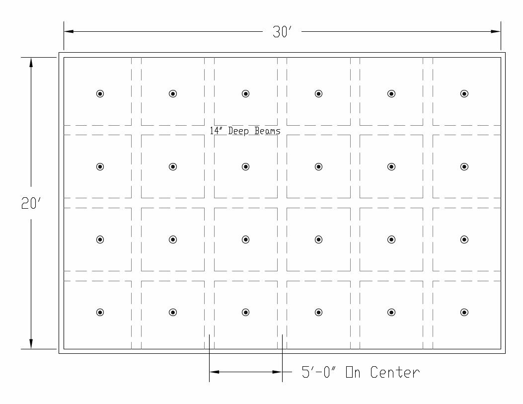

Report on Comments – June 2012 NFPA 13D_______________________________________________________________________________________________13D-46 Log #72 AUT-RSS
_______________________________________________________________________________________________Dana R. Haagensen, Massachusetts Department of Fire Services
13D-68Accept Proposal 13D-68.
The text of 8.1.3.1.2, as written in the 2010 edition, has two major problems. First, it removes anyincentives of the free market system to develop and test residential fire sprinkler systems for prevously un-testedapplications. Second, the wording removes the ability of the AHJ to make sure that the use of fire sprinklers outside oftheir listing limitations has been technically justified given the conditions of a specific local project.Contrary to several comments at the Committee’s Report on Proposals Meeting, the “shall be permitted” language of
this section removes the ability of the AHJ to require technical justification. The Annex material is not enforceable andthe design community is first to say that when an AHJ is referencing Annex text, so the AHJ cannot hang their hat on theexisting Annex language.
No new information has been presented since the rejection of this proposal in the ROP. Theintent of the committee is to continue to require the use of residential sprinklers for all ceiling configurations. Theresponse characteristics along with the droplet sizes created by the deflectors of these sprinklers are consideredappropriate for this occupancy. The AHJ should not be given the opportunity to override this concern of the committee.The number of sprinklers to calculate in the design area and the flows at which to use the sprinklers still have to beapproved by the AHJ per section 8.1.2.3 (Proposal 13D-67 in the ROP).
_______________________________________________________________________________________________13D-47 Log #65 AUT-RSS
_______________________________________________________________________________________________John Desrosier, Tyco Fire Protection Products
13D-70Reconsider committee action on proposal 13D-70 and accept the original proposal including the 3
sq ft of allowable shadow floor area.The committee increased the allowable area from 3 sq ft to 15 sq ft to keep the text similar to NFPA
13. NFPA 13R and NFPA 13D have much different design objectives than NFPA 13. The substantiation for 15 sq ft dryarea was based on a standard sprinkler head which does not address wall wetting. In NFPA 13R and NFPA 13D it iscritical to cool the upper gas layer and wet the walls during a fire condition. Using 15 sq ft of floor area can result in avery large area of unwetted walls. There is a reason NFPA 13R and 13D are not part of NFPA 13 because they areachieving different objectives. If there is an increase in dry area it should be increased due to the testing of a residentialhead or at least due to a substantiation based on residential sprinklers.This comment is being submitted by the Tyco Codes and Standards Sprinkler Task Group.
There is no evidence that the shadow area needs to be limited to 3 sq ft.
29Printed on 10/11/2011
Report on Comments – June 2012 NFPA 13D_______________________________________________________________________________________________13D-48 Log #41 AUT-RSS
_______________________________________________________________________________________________Kenneth E. Isman, National Fire Sprinkler Association
13D-70Revise the new section 8.2.5.7 as follows:
Shadow Areas. Dry areas shall be permitted in the protection area of a sprinkler where walls, or partitions,block direct spray patterns from reaching the floor as long as the dry areas do not exceed 15 sq ft per sprinkler.
The revision accomplishes two tasks. The first is to recognize that the concept of a shadow areaneeds to be limited in application to walls, not other obstructions. The other is to limit the amount of dry areas to helpsatisfy some of the negative ballots on the subject, which have merit.The NFSA Engineering and Standards Committee endorses this comment.
See TC action on 13D-50 (Log #11), which takes into account all comments on the shadowarea installation rules.
_______________________________________________________________________________________________13D-49 Log #57 AUT-RSS
_______________________________________________________________________________________________Kenneth E. Isman, National Fire Sprinkler Association, Inc.
13D-70Revise the new section 8.2.5.7 as follows:
Shadow Areas. Dry areas shall be permitted in the protection area of a sprinkler where walls, or partitions,block direct spray patterns from reaching the floor as long as the dry areas do not exceed 15 sq ft per sprinkler.
The revision accomplishes two tasks. The first is to recognize that the concept of a shadow areaneeds to be limited in application to walls, not other obstructions. The other is to limit the amount of dry areas to helpsatisfy some of the negative ballots on the subject, which have merit.The NFSA Engineering and Standards Committee endorses this comment.
See TC action on 13D-50 (Log #11), which takes into account all comments on the shadowarea installation rules.
30Printed on 10/11/2011
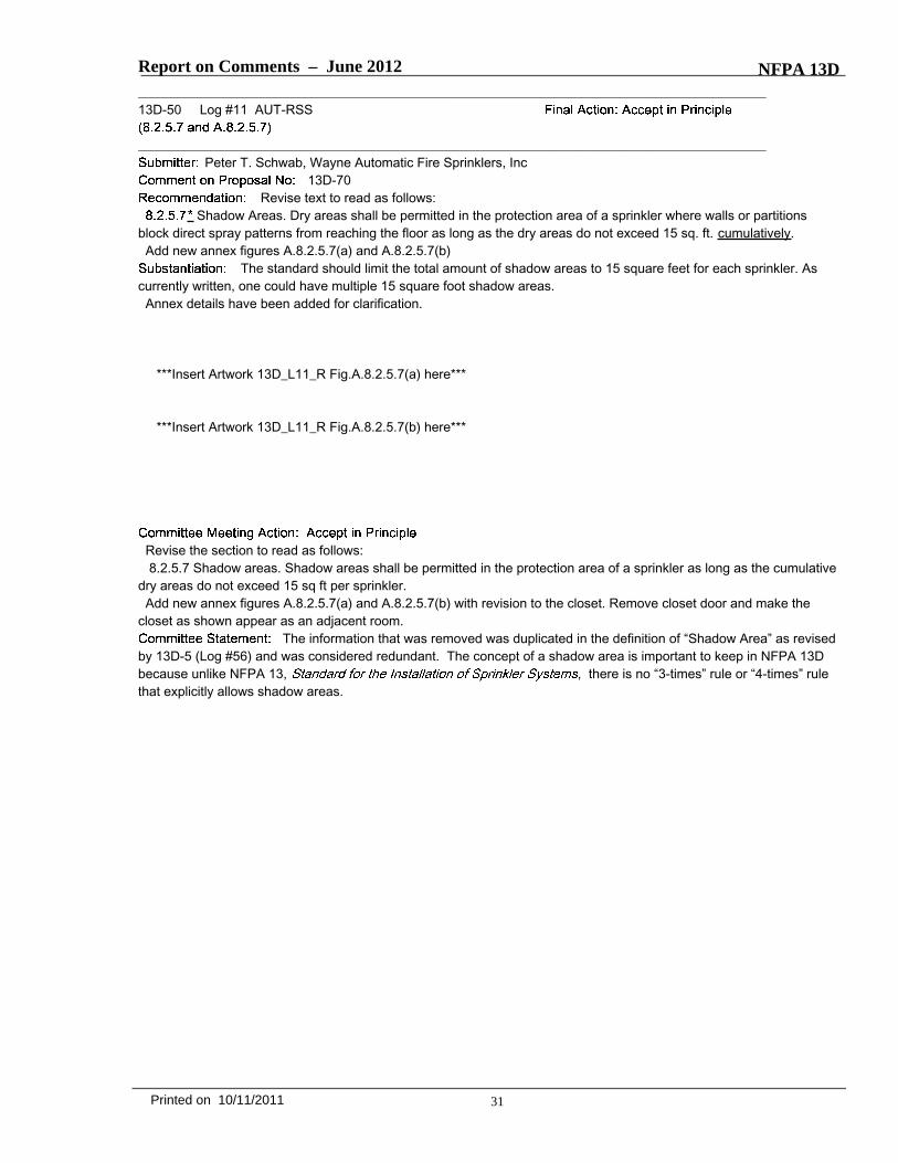
Report on Comments – June 2012 NFPA 13D_______________________________________________________________________________________________13D-50 Log #11 AUT-RSS
_______________________________________________________________________________________________Peter T. Schwab, Wayne Automatic Fire Sprinklers, Inc
13D-70Revise text to read as follows:
Shadow Areas. Dry areas shall be permitted in the protection area of a sprinkler where walls or partitionsblock direct spray patterns from reaching the floor as long as the dry areas do not exceed 15 sq. ft. cumulatively.Add new annex figures A.8.2.5.7(a) and A.8.2.5.7(b)
The standard should limit the total amount of shadow areas to 15 square feet for each sprinkler. Ascurrently written, one could have multiple 15 square foot shadow areas.Annex details have been added for clarification.
***Insert Artwork 13D_L11_R Fig.A.8.2.5.7(a) here***
***Insert Artwork 13D_L11_R Fig.A.8.2.5.7(b) here***
Revise the section to read as follows:8.2.5.7 Shadow areas. Shadow areas shall be permitted in the protection area of a sprinkler as long as the cumulative
dry areas do not exceed 15 sq ft per sprinkler.Add new annex figures A.8.2.5.7(a) and A.8.2.5.7(b) with revision to the closet. Remove closet door and make the
closet as shown appear as an adjacent room.The information that was removed was duplicated in the definition of “Shadow Area” as revised
by 13D-5 (Log #56) and was considered redundant. The concept of a shadow area is important to keep in NFPA 13Dbecause unlike NFPA 13, , there is no “3-times” rule or “4-times” rulethat explicitly allows shadow areas.
31Printed on 10/11/2011
FIGURE A.8.2.5.7 (a) Example of Shadow Areas (SSU/SSP)

FIGURE A.8.2.5.7 (b) Example of Shadow Areas (HSW)

Report on Comments – June 2012 NFPA 13D_______________________________________________________________________________________________13D-51 Log #17 AUT-RSS
_______________________________________________________________________________________________Peter T. Schwab, Wayne Automatic Fire Sprinklers, Inc.
13D-75Add new text to read as follows:
The ambient temperature exposed to the discharge end of the sprinkler shall be determined by using thelowest one-day mean temperature from Figure A.8.2.6.1.Add new Figure A.8.2.6.1 by extracting Figure A.10.5.1 from NFPA 24.
The user needs guidance on how to determine the proper temperature to use when applying Tables8.2.6(a) or (b). Many AHJ's require that the lowest ever recorded temperature be used for the ambient exteriortemperature.This is the second such comment submitted. The first one referenced NFPA 13 Chapter 10. It should have referenced
NFPA 24 since Chapter 10 is an extract in NFPA 13.
Do not make the changes proposed by the submitter.At the end of A.8.2.6 (shown in proposal 13D-75 in the ROP) add, “See Figure A.8.2.6(3).”Add a new Figure A.8.2.6(3) that is the same as Figure A.10.5.1 in the 2010 edition of NFPA 13.
Under NFPA regulations, a section in the body of the standard cannot refer to a figure in theannex as proposed by the submitter, so the reference was moved to the annex.
_______________________________________________________________________________________________13D-52 Log #16 AUT-RSS
_______________________________________________________________________________________________Peter T. Schwab, Wayne Automatic Fire Sprinklers, Inc.
13D-75Add new text to read as follows:
The ambient temperature exposed to the discharge end of the sprinkler shall be determined by using thelowest one-day mean temperature from Figure A.8.2.6.1.Add new Figure A.8.2.6.1 by extracting Figure A.10.5.1 from NFPA 13.
The user needs guidance on how to determine the proper temperature to use when applying Tables8.2.6(a) or (b). Many AHJ's require that the lowest ever recorded temperature be used for the ambient exteriortemperature.
See TC action on 13D-51 (Log #17).
32Printed on 10/11/2011
Report on Comments – June 2012 NFPA 13D_______________________________________________________________________________________________13D-53 Log #33 AUT-RSS
_______________________________________________________________________________________________Kenneth E. Isman, National Fire Sprinkler Association
13D-12Revise text to read as follows:
Perform the following five changes to the antifreeze rules as adopted in Proposal 13D-12:1. Insert at the beginning of 8.3.3.2.4, “Unless the pre-mix solution is listed, the specific gravity of the antifreeze shall
be checked . . .”2. Delete “in accordance with Figure 8.3.3.2.4(a) and 8.3.3.2.4(b)” from the end of section 8.3.3.2.4.3. Move Figures 8.3.3.2.4(a) and 8.3.3.2.4(b) to Figures A.8.3.3.3.2(a) and A.8.3.3.3.2(b)4. Add a new annex note to 8.3.3.2.4 as follows:“A.8.3.3.2.4 The specific gravity for any liquid can be found by taking the density of the liquid at a specific temperature
and dividing it by the density of water at that same temperature. The densities of propylene glycol and glycerine can befound for a wide range of temperatures in Figure A.8.3.3.3.2(a) and Figure A.8.3.3.3.2(b).”5. In the portion of A.8.3.3.3.2 that discusses the use of DL and DH, revise the text to read as follows:DL = density (gm/ml) of antifreeze solution at lowest expected temperature (see Figure A.8.3.3.3.2(a) for the density of
Propylene Glycol at a variety of temperatures and Figure A.8.3.3.3.2(b) for the density of Glycerine at a variety oftemperatures)DH = density (gm/ml) of antifreeze solution at highest expected temperature (see Figure A.8.3.3.3.2(a) for the density of
Propylene Glycol at a variety of temperatures and Figure A.8.3.3.3.2(b) for the density of Glycerine at a variety oftemperatures)
There is no need to check the specific gravity upon initial filling of the system if the solution is listed. Inorder to maintain the listing of the product, the manufacturer needs to prove a level of quality control that insures thecorrect concentration of the solution.As processed in the ROP, Figures 8.3.3.2.4(a) and (b) are referenced in the body (legal requirement) for use in
determining specific gravity. But the specific gravity is not shown in the Figures. The specific gravity can be calculatedfrom the figures, so an annex note has been inserted to let the user know that this can be done.Since the figures provide the user with the physical properties of liquids, which cannot change and are not subject tolegal requirements, it is best to put them in the annex, rather than the body of the standard.This comment has the endorsement of the NFSA Engineering and Standards Committee.
Reject Item #1Accept Items #2-5This data was moved to Chapter 9.
The intent of the committee is to check the specific gravity of an antifreeze solution prior toputting it in the piping, even if the solution is premixed.
33Printed on 10/11/2011
Report on Comments – June 2012 NFPA 13D_______________________________________________________________________________________________13D-54 Log #49 AUT-RSS
_______________________________________________________________________________________________Kenneth E. Isman, National Fire Sprinkler Association, Inc.
13D-12Perform the following five changes to the antifreeze rules as adopted in Proposal 13D-12:
1. Insert at the beginning of 8.3.3.2.4, “Unless the pre-mix solution is listed, the specific gravity of the antifreeze shallbe checked . . .”2. Delete “in accordance with Figure 8.3.3.2.4(a) and 8.3.3.2.4(b)” from the end of section 8.3.3.2.4.3. Move Figures 8.3.3.2.4(a) and 8.3.3.2.4(b) to Figures A.8.3.3.3.2(a) and A.8.3.3.3.2(b)4. Add a new annex note to 8.3.3.2.4 as follows:“A.8.3.3.2.4 The specific gravity for any liquid can be found by taking the density of the liquid at a specific temperature
and dividing it by the density of water at that same temperature. The densities of propylene glycol and glycerine can befound for a wide range of temperatures in Figure A.8.3.3.3.2(a) and Figure A.8.3.3.3.2(b).”5. In the portion of A.8.3.3.3.2 that discusses the use of DL and DH, revise the text to read as follows:DL = density (gm/ml) of antifreeze solution at lowest expected temperature (see Figure A.8.3.3.3.2(a) for the density of
Propylene Glycol at a variety of temperatures and Figure A.8.3.3.3.2(b) for the density of Glycerine at a variety oftemperatures)DH = density (gm/ml) of antifreeze solution at highest expected temperature (see Figure A.8.3.3.3.2(a) for the density of
Propylene Glycol at a variety of temperatures and Figure A.8.3.3.3.2(b) for the density of Glycerine at a variety oftemperatures)
There is no need to check the specific gravity upon initial filling of the system if the solution is listed. Inorder to maintain the listing of the product, the manufacturer needs to prove a level of quality control that insures thecorrect concentration of the solution.As processed in the ROP, Figures 8.3.3.2.4(a) and (b) are referenced in the body (legal requirement) for use in
determining specific gravity. But the specific gravity is not shown in the Figures. The specific gravity can be calculatedfrom the figures, so an annex note has been inserted to let the user know that this can be done.Since the figures provide the user with the physical properties of liquids, which cannot change and are not subject to
legal requirements, it is best to put them in the annex, rather than the body of the standard.This comment has the endorsement of the NFSA Engineering and Standards Committee.
See TC action on 13D-53 (Log #33).
34Printed on 10/11/2011

Report on Comments – June 2012 NFPA 13D_______________________________________________________________________________________________13D-55 Log #29 AUT-RSS
_______________________________________________________________________________________________Bill Galloway, Southern Regional Fire Code Development Committee
13D-82Accept the proposed changes as drafted in the Technical Committee Proposal
Add to 8.4.4 (4)(d) For Flows higher than the manufacturer’s allowable continuous flow, table 8.4.4(g) shall be permitted to be used.In Table 8.4.4(g)Add 40 PSI to the 39 GPM columnIn table 8.4.10.2(b)Add 14 PSI for 22 GPMAdd 16 PSI for 24 GPMAdd 21 PSI for 26 GPMAdd 23 PSI for 28 GPMAdd 25 PSI for 30 GPMAdd 28 PSI for 32 GPM
The Fire Protection Research Foundation study results on water meters needs to be incorporated intothe prescriptive design charts of 13D. To ignore those results could potentially result in underdesigned systems.
The submitter did not indicate which size meter these pressure losses would apply to. See also13D-56 (Log #13), 13D-57 (Log #14), 13D-58 (Log #15) and 13D-73 (Log #62) where additional modifications weremade to the sections dealing with friction loss for water meters .
_______________________________________________________________________________________________13D-56 Log #13 AUT-RSS
_______________________________________________________________________________________________Peter T. Schwab, Wayne Automatic Fire Sprinklers, Inc
13D-82Add new 10.4.4 (4) (b) and re-letter (b) & (c) to (c) & (d)
(b) For flows higher than the manufacturer’s allowable continuous flow, table 10.4.4 (g) shall be permitted to be used.It is more appropriate to place this language immediately after 10.4.4 (4) (a). This language is
important and should be included in 10.4.4. Many meter manufacturers will publish a “maximum continuous flow” fortheir meters. This is generally the highest flow that can be measured with great accuracy. Many AHJ’s will not allowmore water through the meter than what the manufacturer indicates is the maximum flow. As evidenced in the FPRFtesting, meters can easily handle greater flows from a friction loss and durability standpoint.
Do not accept a new part (b).Revise (a) to read, “Table 10.4.4(g) shall be permitted to be used, even where the sprinkler demand flow exceeds the
meter’s rated continuous flow”Rather than put another subsection into the standard to reference the same table as part (a),
the statement was modified to fit with part (a).
35Printed on 10/11/2011

Report on Comments – June 2012 NFPA 13D_______________________________________________________________________________________________13D-57 Log #14 AUT-RSS
_______________________________________________________________________________________________Peter T. Schwab, Wayne Automatic Fire Sprinklers, Inc
13D-82Modify Table 10.4.4 (g) as follows:
***INSERT Table 13D_L14_R_TB10.4.4(g) here***
Based on the FPRF report on pressure loss through water meters, pressure losses were added for aflow of 39 GPM. Even though there were some ⅝ & ¾ meters that handled 52 GPM, they were not added because atthat flow a 1” meter should be used or refer to the manufacturer’s literature. The other ⅝ & ¾ pressure losses were leftas is based on the testing. The numbers for the ⅝ meters were close to the existing language in 13D. The ¾ metersseemed to be substantially more than 13D (3 of 4) so changes have been made.
_______________________________________________________________________________________________13D-58 Log #15 AUT-RSS
_______________________________________________________________________________________________Peter T. Schwab, Wayne Automatic Fire Sprinklers, Inc
13D-82Delete Table 10.4.10.2 (b)
Modify 10.4.10.2 (3) as follows
Step 3 — Determine PLm. Use Table 10.4.10.2(b) 10.4.4(g) to determine the pressure loss from the water meterbased on the selected water meter size. Where the actual water meter pressure loss is known, PLm shall be the actualloss.
It makes more sense to have a single table to present the same data. Also, the prescriptive methodtable reflects the 20 GPM cutoff for maximum continuous flow. The FPRF testing has proven otherwise. One of thefootnotes in the deleted table was added to 10.4.10.2 (3). The other footnote is addressed in 10.4.10.2 (4)
36Printed on 10/11/2011
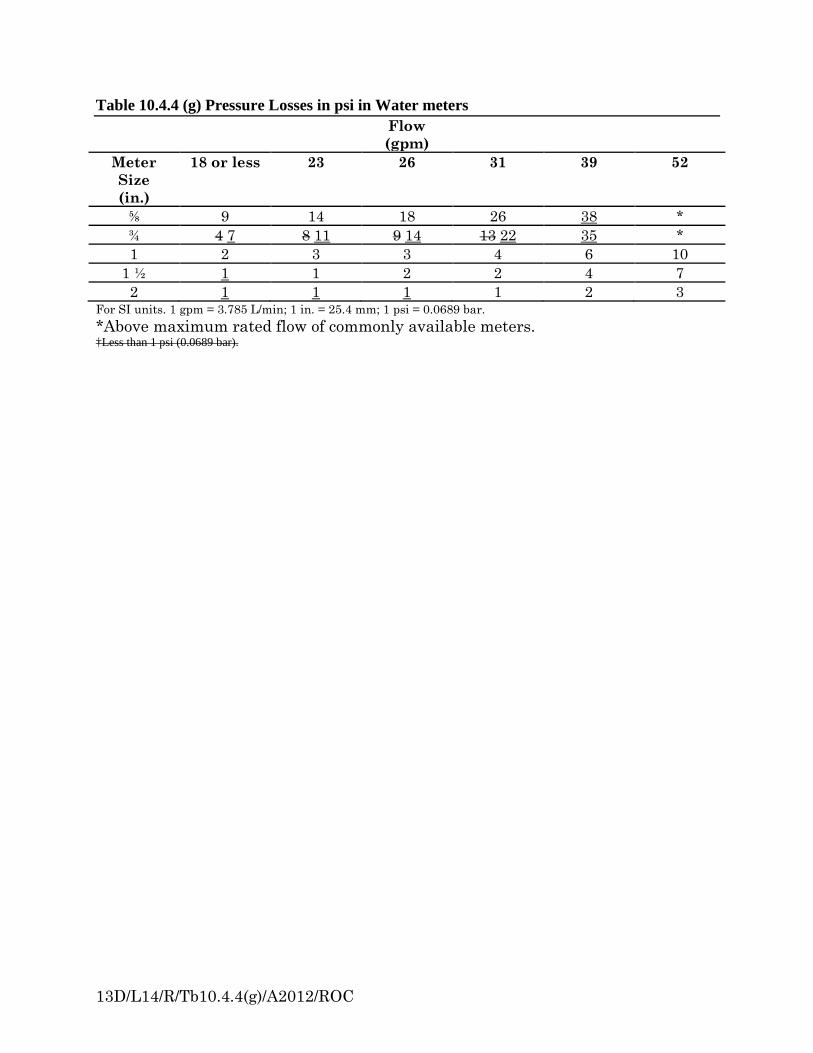
13D/L14/R/Tb10.4.4(g)/A2012/ROC
Table 10.4.4 (g) Pressure Losses in psi in Water meters Flow
(gpm)
Meter Size (in.)
18 or less 23 26 31 39 52
⅝ 9 14 18 26 38 * ¾ 4 7 8 11 9 14 13 22 35 * 1 2 3 3 4 6 10
1 ½ 1 1 2 2 4 7 2 1 1 1 1 2 3
For SI units. 1 gpm = 3.785 L/min; 1 in. = 25.4 mm; 1 psi = 0.0689 bar. *Above maximum rated flow of commonly available meters. †Less than 1 psi (0.0689 bar).

Report on Comments – June 2012 NFPA 13D_______________________________________________________________________________________________13D-59 Log #27 AUT-RSS
_______________________________________________________________________________________________Jeffrey Feid, State Farm Insurance Company
13D-94Revise text to read as follows:
A wet pipe system shall be permitted to be used where all piping is installed inareas maintained above 40°F (4°C).
including When there is no heated path to a sprinkler location, wet pipe systems shall bepermitted in spaces areas properly insulated to maintain 40°F (4°C).
Where system piping is located in areas not maintained above 40°F (4°C), the pipe shall beprotected against freezing by use of one of the following methods:(1) Dry pipe system and preaction systems in accordance with 8.3.4(2) Antifreeze system in accordance with 8.3.3(3) Listed standard dry-pendent or dry-sidewall sprinklers extended from pipe in heated areas into unheated areas not
intended for living purposesRenumber A9.1.1 to A9.1.1.1 delete existing figures and insert new figures (old) A.8.3.1 to be A.8.3.1.1
***INSERT FIGURES HERE***Figure A.9.1.1.1(a)Figure A,9.1.1.1(b)Figure A.9.1.1.1(c)
This creates more consistent sub sections to conform to manual of style. The section numberingreflects the new Chapter 9 ITM numbering. It indicates the requirements for properly insulated spaces to protect pipesfrom temperatures below 40 F. The annex figures are updated and refreshed to indicate more typical and modernconstruction techniques and materials.
The existing section format conforms to the manual of style and does not need to be changed.The Chapter 9 numbering will be updated as a part of the preparation of the new edition without this comment. Thefigures impose requirements and construction techniques that are not required by the standard. There is no need tocreate a sloped space around the pipe as proposed by Figure A.9.1.1.1(a). The prohibition on notching joists stated inproposed Figure A.9.1.1.1(b) is not correct. Joists can be notched if done correctly in agreement with theengineer/architect.
37Printed on 10/11/2011
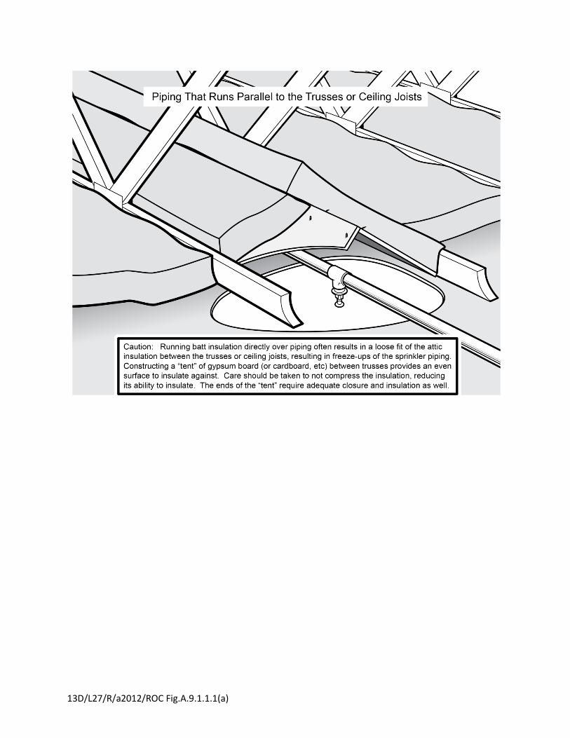
13D/L27/R/a2012/ROC Fig.A.9.1.1.1(a)
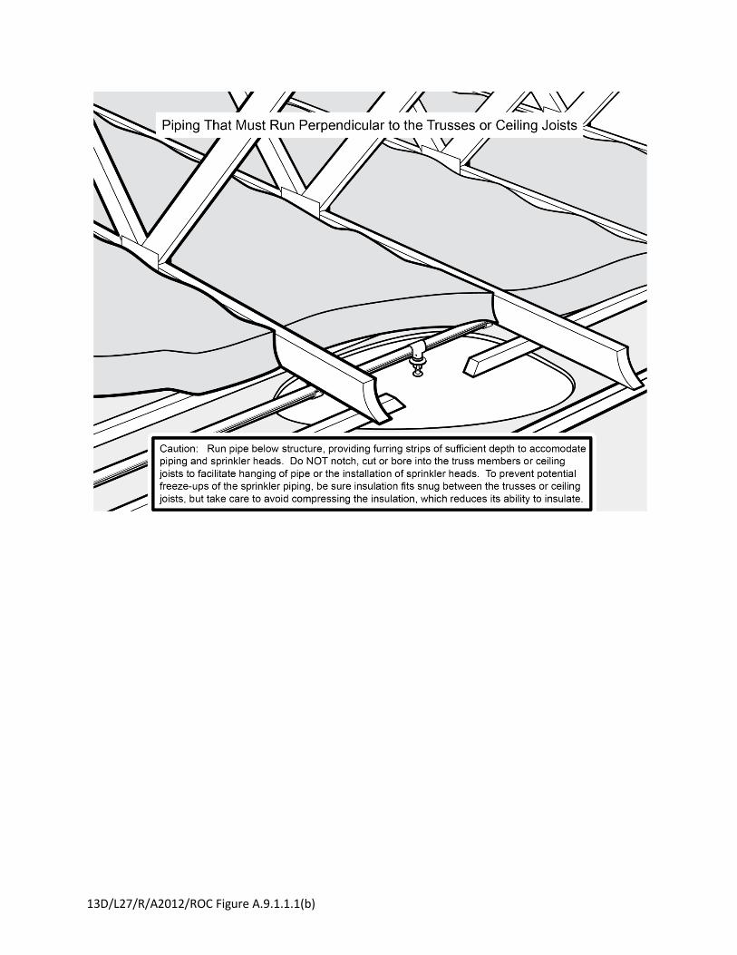
13D/L27/R/A2012/ROC Figure A.9.1.1.1(b)
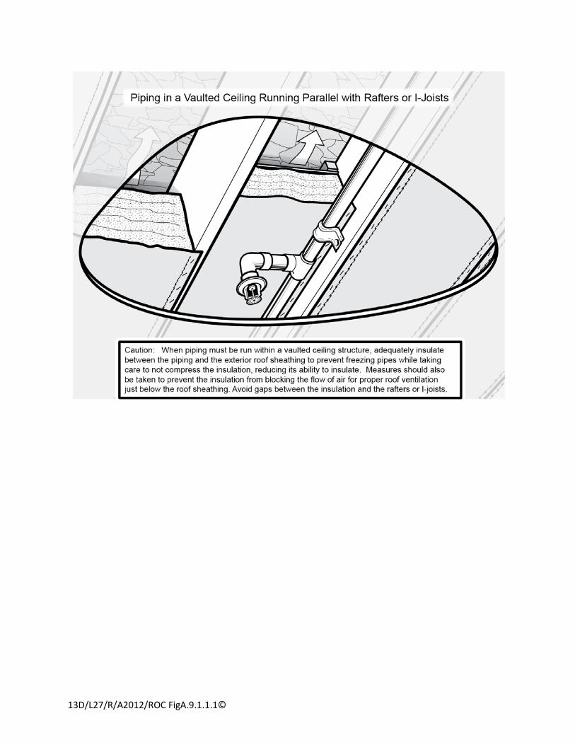
13D/L27/R/A2012/ROC FigA.9.1.1.1©
Report on Comments – June 2012 NFPA 13D_______________________________________________________________________________________________13D-60 Log #22 AUT-RSS
_______________________________________________________________________________________________Victoria B. Valentine, National Fire Sprinkler Association
13D-97Revise text to read as follows:
Any sprinkler that is oOperated, damaged, corroded, loaded with foreign materials or showing signs of leakageor damaged sprinklers shall be replaced with a new listed sprinklers having the same performance characteristics as theoriginal equipment.
Requirements related to replacing sprinklers that are corroded, loaded, or showing signs of leakageare needed to provide a level of assurance that the sprinklers will operate as intended.This proposal was developed by the UL/FM/NFSA Standards Review Committee.
Replace "loaded' with 'covered" and change "sprinklers" in the second line to "sprinkler". Section would read as follows:12.3.2* Any sprinkler that is oOperated, damaged, corroded, loaded coveredwith foreign materials or showing signs of
leakage or damaged sprinklers shall be replaced with a new listed sprinklers having the same performancecharacteristics as the original equipment.
The use of the word "covered" rather than "loaded" is believed to be better understood by thehomeowner.
_______________________________________________________________________________________________13D-61 Log #35 AUT-RSS
_______________________________________________________________________________________________Kenneth E. Isman, National Fire Sprinkler Association
13D-22Revise text to read as follows:
Delete the redundant “rating” in the middle of the new annex note and add a new sentence as follows:In most installations, pressure increases due to temperature fluctuations or pressure surges do not cause the
system pressure to exceed the pressure rating rating of the pipe. In situations where the system pressure has thepotential to exceed the pipe pressure rating, installation of a relief valve should be considered. Where a relief valve isinstalled, consideration should be given to making sure that an adequate drain is available to handle the anticipateddischarge.
Fixing a typo and adding helpful guidance on consideration for the discharge of relief valves. Wehave heard of situations where relief valves were installed in attics with no way to get the discharge out of the home.This comment has the endorsement of the NFSA Engineering and Standards Committee.
38Printed on 10/11/2011
Report on Comments – June 2012 NFPA 13D_______________________________________________________________________________________________13D-62 Log #51 AUT-RSS
_______________________________________________________________________________________________Kenneth E. Isman, National Fire Sprinkler Association, Inc.
13D-22Delete the redundant “rating” in the middle of the new annex note and add a new sentence as
follows:In most installations, pressure increases due to temperature fluctuations or pressure surges do not cause the
system pressure to exceed the pressure rating rating of the pipe. In situations where the system pressure has thepotential to exceed the pipe pressure rating, installation of a relief valve should be considered. Where a relief valve isinstalled, consideration should be given to making sure that an adequate drain is available to handle the anticipateddischarge.
Fixing a typo and adding helpful guidance on consideration for the discharge of relief valves. We haveheard of situations where relief valves were installed in attics with no way to get the discharge out of the home.This comment has the endorsement of the NFSA Engineering and Standards Committee.
_______________________________________________________________________________________________13D-63 Log #44 AUT-RSS
_______________________________________________________________________________________________Kenneth E. Isman, National Fire Sprinkler Association
13D-103, 13D-67Do not use the figures from the ROP, but in the figures currently in NFPA 13D, change the term
“Rubber-faced check valve” to “Check valve or backflow preventer”.The reference to a backflow preventer serving this purpose was the only positive part of redrawing the
figures that we could see. While we are not in favor of mandatory backflow devices on residential sprinkler systems, werecognize that some water authorities require such devices and when they are installed, there is no need for anadditional check valve.
_______________________________________________________________________________________________13D-64 Log #61 AUT-RSS
_______________________________________________________________________________________________Kenneth E. Isman, National Fire Sprinkler Association, Inc.
13D-103Do not use the figures from the ROP, but in the figures currently in NFPA 13D, change the term
“Rubber-faced check valve” to “Check valve or backflow preventer”.The reference to a backflow preventer serving this purpose was the only positive part of redrawing the
figures that we could see. While we are not in favor of mandatory backflow devices on residential sprinkler systems, werecognize that some water authorities require such devices and when they are installed, there is no need for anadditional check valve.
39Printed on 10/11/2011
Report on Comments – June 2012 NFPA 13D_______________________________________________________________________________________________13D-65 Log #73 AUT-RSS
_______________________________________________________________________________________________Dana R. Haagensen, Massachusetts Department of Fire Services
13D-103In the Figures of A.6.2, remove all water meters, backflow preventors and waterflow switches.
There are many that still believe that these devices are required by NFPA 13D. We should be doingeverything possible to encourage straight wet sprinkler systems without such devices.
The TC is not accepting the proposed figures from the ROP and is reverting back to theexisting figures as modified by 13D-63 (Log #44).
_______________________________________________________________________________________________13D-66 Log #30 AUT-RSS
_______________________________________________________________________________________________Bill Galloway, Southern Regional Fire Code Development Committee
13D-103Accept the proposed diagrams as submit in the Technical Committee Proposal.
The proposed diagrams provide an improved representation of a typical underground supply for a 13Dsystem. Including the references to a BFP, in lieu of a check-valve, is appropriate and will help when dealing with waterutilities.
The number of arrangements and which is preferred and not preferred is complicated. The TCwill address this off cycle and revise the annex figures as part of a task group.
_______________________________________________________________________________________________13D-67 Log #7 AUT-RSS
_______________________________________________________________________________________________Peter T. Schwab, Wayne Automatic Fire Sprinklers, Inc
13D-103Accept changes as indicated.
A check valve or backflow is acceptable as the system check valve.
The TC is not accepting the proposed figures from the ROP and is reverting back to theexisting figures as modified by 13D-63 (Log #44).
40Printed on 10/11/2011
Report on Comments – June 2012 NFPA 13D_______________________________________________________________________________________________13D-68 Log #32 AUT-RSS
_______________________________________________________________________________________________Terry L. Victor, Tyco/SimplexGrinnell
13D-58Revise text to read as follows:
Accept proposal 13D- 58 (Log #66) as submitted and add new annex text to A.7.6 as follows:The waterflow detection device and the audible alarm device do not have to be listed. The local waterflow alarm
is intended to be a single alarm audible...".A waterflow alarm should be provided on every sprinkler system. Most municipalities that require
residential fire sprinkler systems also require a waterflow alarm on each system. The benefits of having one far outweighthe minimal cost of installing it. The cost studies submitted to the technical committee are based on using a listedwaterflow detection device when this is not required in accordance with 5.1.3. The waterflow detection device canprovide a local audible signal only, or can also be wired into the existing burglar or fire alarm system. This comment isbeing submitted by the Tyco Codes and Standards Sprinkler Task Group.
Do not accept section 7.6 from proposal 13D- 58 (Log #66) as submitted.Add new annex text to A.7.6 as follows:
The waterflow detection device and the audible alarm device do not have to be listed. The local waterflow alarmis intended to be a single alarm audible...".
The TC believes that smoke alarms are more sensitive than waterflow devices in detecting andalerting building occupants to fire conditions. As such waterflow devices and alarms are not needed as a life safetydevice where smoke alarms or smoke detectors are installed in dwelling units. While the TC believes that installing ameans for detecting water flow during a non-fire situation is beneficial and advisable, it is not necessary for life safetywhere smoke alarms or smoke detectors are present, and therefore waterflow alarms should not be mandated by thestandard where smoke alarms or smoke detectors are present.
_______________________________________________________________________________________________13D-69 Log #12 AUT-RSS
_______________________________________________________________________________________________Peter T. Schwab, Wayne Automatic Fire Sprinklers, Inc
13D-70Delete A.8.2.5.7
A.8.2.5.7 Corridors being protected with sidewall sprinklers will frequently have small areas behind the sprinklers thatare inset for a doorway. Even though these areas are slightly behind the sprinklers, it is not the intent of 13D to requireadditional sprinkler protection in these doorways.
Delete this section as it really does not apply to 13D occupancies. Corridors are generally associatedwith multiple dwelling units. Townhouses protected under 13D will overwhelmingly be separated by 1 or 2 hour wallsand each unit will have direct access from the exterior. Duplexes also as a rule will also be constructed in this way andthe likelihood of an interior corridor is the exception, not the rule. This or similar language belongs in NFPA 13R andNFPA 13.
This configuration can exist in homes and this statement provides guidance.
41Printed on 10/11/2011

Report on Comments – June 2012 NFPA 13D_______________________________________________________________________________________________13D-70 Log #63 AUT-RSS
_______________________________________________________________________________________________Brian Larkin, Tyco Thermal Controls
13D-107Accept proposal 13D-107 as follows:
Where listed heat tracing is used on CPVC piping, it must be certified as compatible with the CPVC piping.There is no certification program for CPVC compatibility; however, products may be tested for
compatibility.This comment is being submitted by the Tyco Codes and Standards Task Group.
Do not accept the language from Proposal 13-107.Insert a new annex note to A.9.1.2(4) as follows:
Where listed heat tracing is used on CPVC piping, it should be compatible with the CPVC piping.This is the correct location for such an annex note.
_______________________________________________________________________________________________13D-71 Log #71 AUT-RSS
_______________________________________________________________________________________________Dana R. Haagensen, Massachusetts Department of Fire Services
13D-12Delete Table A.8.3.3.2.1 and revise A.8.3.3.2.1 to read: “See Table A.8.3.3.2.1 the pre-mixed
antifreeze manufacturer’s technical data sheets to determine the freeze point of the solution.”One of the major manufacturers of antifreeze solutions for the fire sprinkler industry publishes freeze
points that significantly differ than indicated in the NFPA chart. In the case of one project, the NFPA information misledthe installing contractor to believe that antifreeze could be used within the new concentration limitations and localclimate conditions. Upon researching the freeze points from the manufacturers, this discrepancy was uncovered.
Do not make the changes proposed by the comment.Revise existing section A.8.3.3.2.1 as follows:A.8.3.3.2.1 See Table A.8.3.3.2.1. The manufacture’s technical data sheets may include specific information on the
properties of their antifreeze solutions.The Table is in the annex and is not legally enforceable. The information is useful in a general
sense to help people understand the basic ranges in which different concentrations begin to freeze. It is not intended tosubstitute for manufacturer’s information.
42Printed on 10/11/2011

Report on Comments – June 2012 NFPA 13D_______________________________________________________________________________________________13D-72 Log #70 AUT-RSS
_______________________________________________________________________________________________Dana R. Haagensen, Massachusetts Department of Fire Services
13D-12Add the following sentence to the beginning of A.8.3.3.2.3: “The minimum design temperature with
which the antifreeze concentration is determined shall be based on local weather history and not the NFPA Figure titled‘Isothermal Lines’.”
The method of determination of the lowest temperature in the NFPA ‘Isothermal Lines’ figure is notnecessarily representative of average low winter temperatures. In the case of one project, the NFPA information misledthe installing contractor to believe that antifreeze could be used within the new concentration limitations and localclimate conditions. Upon researching the local weather data, this discrepancy was uncovered.
The appropriate temperatures to use when determining the freeze protection for a systemshould be determined by the design professional.
43Printed on 10/11/2011
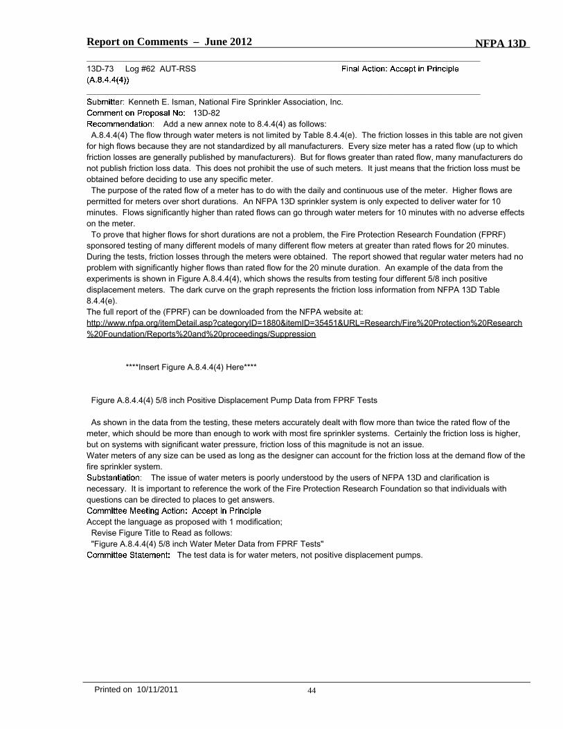
Report on Comments – June 2012 NFPA 13D_______________________________________________________________________________________________13D-73 Log #62 AUT-RSS
_______________________________________________________________________________________________Kenneth E. Isman, National Fire Sprinkler Association, Inc.
13D-82Add a new annex note to 8.4.4(4) as follows:
A.8.4.4(4) The flow through water meters is not limited by Table 8.4.4(e). The friction losses in this table are not givenfor high flows because they are not standardized by all manufacturers. Every size meter has a rated flow (up to whichfriction losses are generally published by manufacturers). But for flows greater than rated flow, many manufacturers donot publish friction loss data. This does not prohibit the use of such meters. It just means that the friction loss must beobtained before deciding to use any specific meter.The purpose of the rated flow of a meter has to do with the daily and continuous use of the meter. Higher flows are
permitted for meters over short durations. An NFPA 13D sprinkler system is only expected to deliver water for 10minutes. Flows significantly higher than rated flows can go through water meters for 10 minutes with no adverse effectson the meter.To prove that higher flows for short durations are not a problem, the Fire Protection Research Foundation (FPRF)
sponsored testing of many different models of many different flow meters at greater than rated flows for 20 minutes.During the tests, friction losses through the meters were obtained. The report showed that regular water meters had noproblem with significantly higher flows than rated flow for the 20 minute duration. An example of the data from theexperiments is shown in Figure A.8.4.4(4), which shows the results from testing four different 5/8 inch positivedisplacement meters. The dark curve on the graph represents the friction loss information from NFPA 13D Table8.4.4(e).The full report of the (FPRF) can be downloaded from the NFPA website at:http://www.nfpa.org/itemDetail.asp?categoryID=1880&itemID=35451&URL=Research/Fire%20Protection%20Research%20Foundation/Reports%20and%20proceedings/Suppression
****Insert Figure A.8.4.4(4) Here****
Figure A.8.4.4(4) 5/8 inch Positive Displacement Pump Data from FPRF Tests
As shown in the data from the testing, these meters accurately dealt with flow more than twice the rated flow of themeter, which should be more than enough to work with most fire sprinkler systems. Certainly the friction loss is higher,but on systems with significant water pressure, friction loss of this magnitude is not an issue.Water meters of any size can be used as long as the designer can account for the friction loss at the demand flow of thefire sprinkler system.
The issue of water meters is poorly understood by the users of NFPA 13D and clarification isnecessary. It is important to reference the work of the Fire Protection Research Foundation so that individuals withquestions can be directed to places to get answers.
Accept the language as proposed with 1 modification;Revise Figure Title to Read as follows:"Figure A.8.4.4(4) 5/8 inch Water Meter Data from FPRF Tests"
The test data is for water meters, not positive displacement pumps.
44Printed on 10/11/2011

13D/L62/Fig A.8.4.4(4)/A2012/ROC
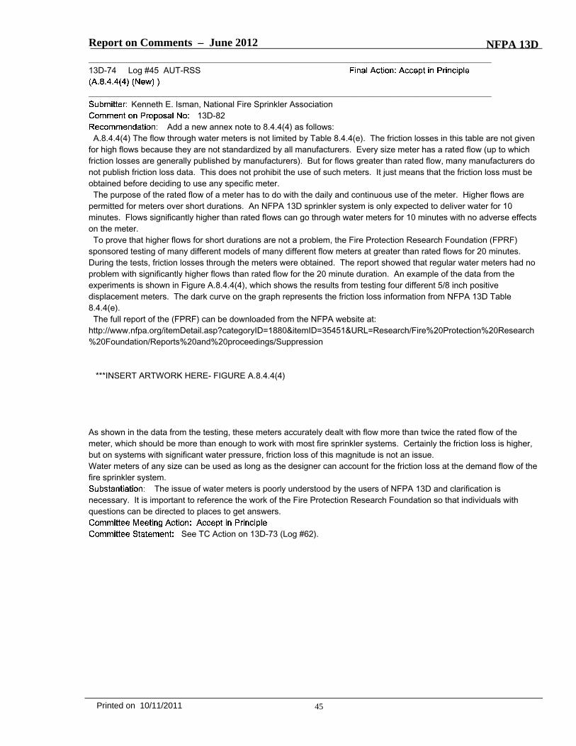
Report on Comments – June 2012 NFPA 13D_______________________________________________________________________________________________13D-74 Log #45 AUT-RSS
_______________________________________________________________________________________________Kenneth E. Isman, National Fire Sprinkler Association
13D-82Add a new annex note to 8.4.4(4) as follows:
A.8.4.4(4) The flow through water meters is not limited by Table 8.4.4(e). The friction losses in this table are not givenfor high flows because they are not standardized by all manufacturers. Every size meter has a rated flow (up to whichfriction losses are generally published by manufacturers). But for flows greater than rated flow, many manufacturers donot publish friction loss data. This does not prohibit the use of such meters. It just means that the friction loss must beobtained before deciding to use any specific meter.The purpose of the rated flow of a meter has to do with the daily and continuous use of the meter. Higher flows are
permitted for meters over short durations. An NFPA 13D sprinkler system is only expected to deliver water for 10minutes. Flows significantly higher than rated flows can go through water meters for 10 minutes with no adverse effectson the meter.To prove that higher flows for short durations are not a problem, the Fire Protection Research Foundation (FPRF)
sponsored testing of many different models of many different flow meters at greater than rated flows for 20 minutes.During the tests, friction losses through the meters were obtained. The report showed that regular water meters had noproblem with significantly higher flows than rated flow for the 20 minute duration. An example of the data from theexperiments is shown in Figure A.8.4.4(4), which shows the results from testing four different 5/8 inch positivedisplacement meters. The dark curve on the graph represents the friction loss information from NFPA 13D Table8.4.4(e).The full report of the (FPRF) can be downloaded from the NFPA website at:
http://www.nfpa.org/itemDetail.asp?categoryID=1880&itemID=35451&URL=Research/Fire%20Protection%20Research%20Foundation/Reports%20and%20proceedings/Suppression
***INSERT ARTWORK HERE- FIGURE A.8.4.4(4)
As shown in the data from the testing, these meters accurately dealt with flow more than twice the rated flow of themeter, which should be more than enough to work with most fire sprinkler systems. Certainly the friction loss is higher,but on systems with significant water pressure, friction loss of this magnitude is not an issue.Water meters of any size can be used as long as the designer can account for the friction loss at the demand flow of thefire sprinkler system.
The issue of water meters is poorly understood by the users of NFPA 13D and clarification isnecessary. It is important to reference the work of the Fire Protection Research Foundation so that individuals withquestions can be directed to places to get answers.
See TC Action on 13D-73 (Log #62).
45Printed on 10/11/2011

13D/L45/R/A2012/ROC
Figure A.8.4.4(4) 5/8 inch Positive Displacement Pump Data from FPRF Tests
Report on Comments – June 2012 NFPA 13D_______________________________________________________________________________________________13D-75 Log #CC4 AUT-RSS
_______________________________________________________________________________________________Technical Committee on Residential Sprinkler Systems,
13D-94Committee Comment (tied to Proposal 13D-94) to add a sentence to the end of existing annex note
A.8.3.1 (which will be renumbered A.9.1.1 due to Proposal 13D-94 as follows:Sprinkler Insulation:A Literature ReviewJuly 2011“The Fire Protection Research Foundation completed a research project on the use of insulation to protect sprinkler
pipe from freezing that can be downloaded for free from their website.”The TC wants to provide guidance on insulation practices as identified in the FPRF report.
_______________________________________________________________________________________________13D-76 Log #21 AUT-RSS
_______________________________________________________________________________________________Victoria B. Valentine, National Fire Sprinkler Association
13D-97Revise the text to read as follows:
(5) Ongoing visual inspection of all sprinklers to make sure they are not obstructed, damaged, corroded, loaded withforeign materials, field painted, showing signs of leakage and that decorations are not attached to or hung from them.
Guidance related to inspecting sprinklers for corrosion, loading, field painting and leakage is needed toprovide a level of assurance that the sprinklers will operate as intended.This proposal was developed by the UL/FM/NFSA Standards Review Committee.
Replace the term "loaded" with "covered"(5) Ongoing visual inspection of all sprinklers to make sure they are not obstructed, damaged, corroded, loaded
covered with foreign materials, field painted, showing signs of leakage and that decorations are not attached to or hungfrom them.
The term covered is more easily understood by homeowners.
_______________________________________________________________________________________________13D-77 Log #43 AUT-RSS
_______________________________________________________________________________________________Kenneth E. Isman, National Fire Sprinkler Association
13D-27Insert a new A.12.2.1(6) as follows and renumber the old (6) as (7):
(6) Annually, fully open the test connection downstream of any pressure reducing or regulating valve and make surethat the pressure gage reads a reasonable value.
With the inclusion of a pressure reducing or regulating device, there should be some testing of thedevice.This was agreed to at the E&S meeting in April 2011.
46Printed on 10/11/2011
Report on Comments – June 2012 NFPA 13D_______________________________________________________________________________________________13D-78 Log #59 AUT-RSS
_______________________________________________________________________________________________Kenneth E. Isman, National Fire Sprinkler Association, Inc.
13D-27Insert a new A.12.2.1(6) as follows and renumber the old (6) as (7):
(6) Annually, fully open the test connection downstream of any pressure reducing or regulating valve and make surethat the pressure gage reads a reasonable value.
With the inclusion of a pressure reducing or regulating device, there should be some testing of thedevice.This was agreed to at the E&S meeting in April 2011.
47Printed on 10/11/2011