
13 DAVID SUTTON PICTURES
43
13 DAVID SUTTON
-
Upload
dr-muhammad-bin-zulfiqar -
Category
Education
-
view
621 -
download
3
Transcript of 13 DAVID SUTTON PICTURES

13
DAVID SUTTON

DAVID SUTTON PICTURES
DR. Muhammad Bin Zulfiqar
PGR-FCPS III SIMS/SHL

• Fig. 13.1 Selective left coronary angiogram in the right anterior oblique projection. The arrow indicates a well-demarcated ulceration of an atheromatous plaque in the circumflex artery.
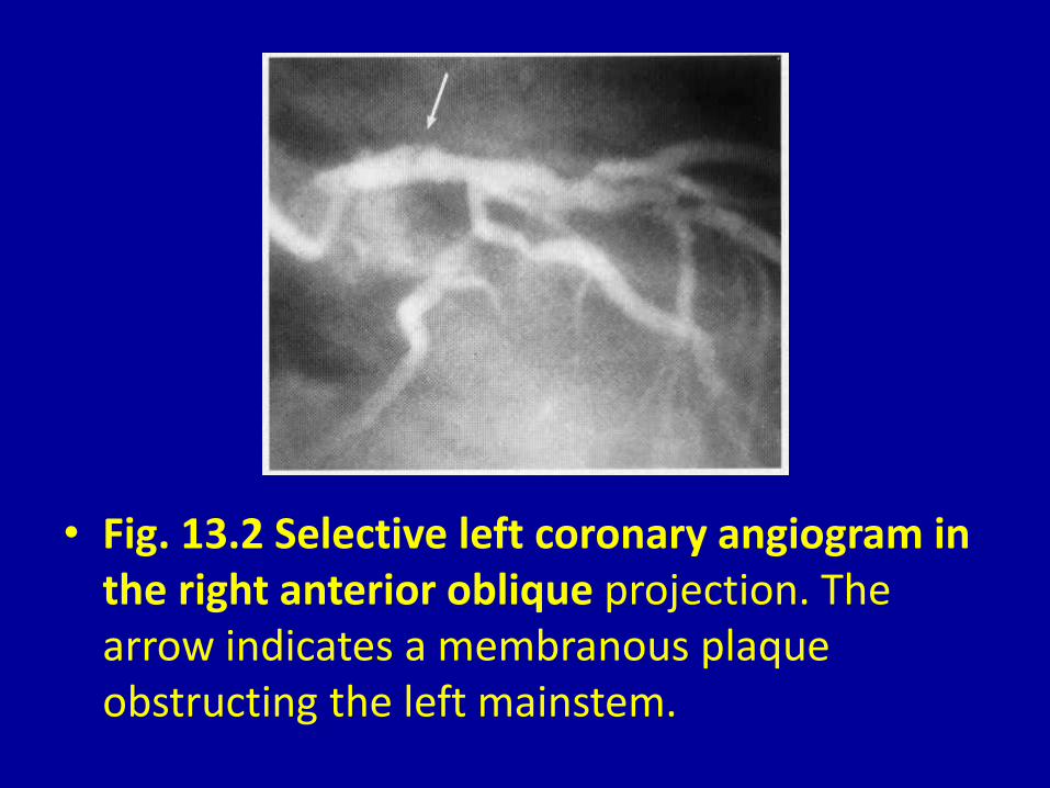
• Fig. 13.2 Selective left coronary angiogram in the right anterior oblique projection. The arrow indicates a membranous plaque obstructing the left mainstem.

• Fig. 13.3 Left ventricular angiogram in the right anterior oblique projection showing severe mitral regurgitation. The large left atrium is densely opacified and the mitral valve is arrowed.
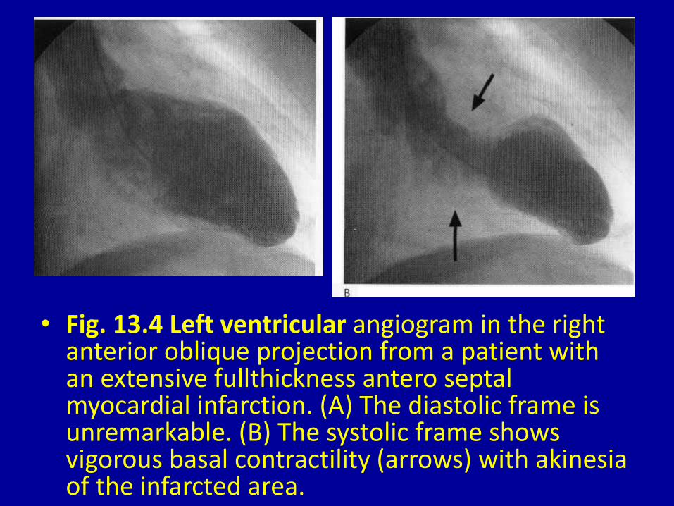
• Fig. 13.4 Left ventricular angiogram in the right anterior oblique projection from a patient with an extensive fullthickness antero septal myocardial infarction. (A) The diastolic frame is unremarkable. (B) The systolic frame shows vigorous basal contractility (arrows) with akinesia of the infarcted area.
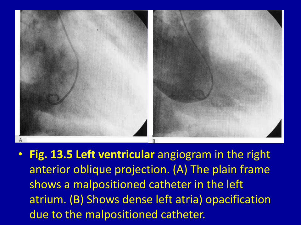
• Fig. 13.5 Left ventricular angiogram in the right anterior oblique projection. (A) The plain frame shows a malpositioned catheter in the left atrium. (B) Shows dense left atria) opacification due to the malpositioned catheter.
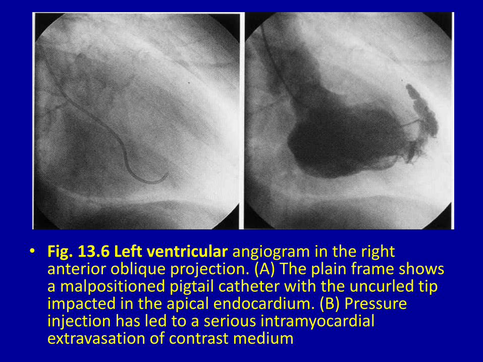
• Fig. 13.6 Left ventricular angiogram in the right anterior oblique projection. (A) The plain frame shows a malpositioned pigtail catheter with the uncurled tip impacted in the apical endocardium. (B) Pressure injection has led to a serious intramyocardial extravasation of contrast medium
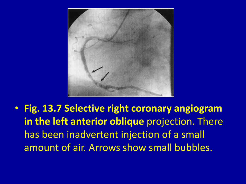
• Fig. 13.7 Selective right coronary angiogram in the left anterior oblique projection. There has been inadvertent injection of a small amount of air. Arrows show small bubbles.

• Fig. 13.8 Selective left coronary angiogram in the left anterior oblique projection. (A) The left ludkins catheter tip is upwardly angled against the wall of the left mainstem. (B) An improved position with the catheter tip axially aligned.

• Fig. 13.9 Bifurcation in three orthogonal views. (A) Foreshortening of the branches. (B) Overlapping of the branches. (C) The only projection that fully demonstrates the bifurcation.

• Fig. 13.10 Selective right coronary angiogram in the left anterior oblique projection. (A) The proximal portions of the posterior descending and left ventricular branches are foreshortened. (B) Addition of caudocranial angulation opens the bifurcations and reveals a stenosis at the origin of the left ventricular branch.

a
• Fig. 13.11 Selective left coronary angiogram in a patient with occlusion of a large intermediate branch. (A) The right anterior oblique view shows overlapping (arrow) of the intermediate and left anterior descending branches. (B) The left anterior oblique view shows foreshortening (arrow) of the occluded branch. (C) Addition of craniocaudal angulation to the left anterior oblique view allows clear demonstration of the occluded branch (arrow).

• Fig. 13.12 Selective left coronary angiogram in the right anterior oblique projection. (A) An early frame shows no vessel lying between the upper left anterior descending branch and the circumflex branch. (B) A later view shows late collateral filling of an occluded obtuse marginal vessel (arrows).

• Fig. 13.13 (A) Selective left coronary angiogram in the right anterior oblique projection showing occlusion of the left anterior descending artery (arrow shows site of occlusion). (B) Selective right coronary angiogram of the same patient in the right anterior oblique projection-there is no evidence of collateral filling of the occluded vessel. (C) Repositioning of the catheter tip more anteriorly engages the ostium of the conus branch-collateral vessels to the occluded branch are revealed (arrow).

• Fig. 13.13 (A) Selective left coronary angiogram in the right anterior oblique projection showing occlusion of the left anterior descending artery (arrow shows site of occlusion). (B) Selective right coronary angiogram of the same patient in the right anterior oblique projection-there is no evidence of collateral filling of the occluded vessel. (C) Repositioning of the catheter tip more anteriorly engages the ostium of the conus branch-collateral vessels to the occluded branch are revealed (arrow).
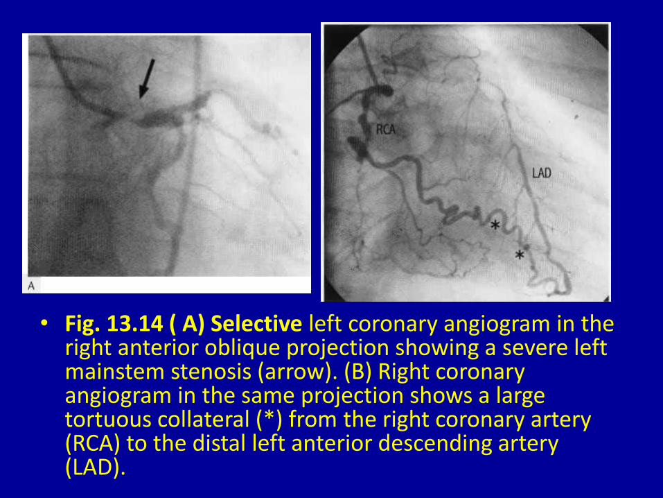
• Fig. 13.14 ( A) Selective left coronary angiogram in the right anterior oblique projection showing a severe left mainstem stenosis (arrow). (B) Right coronary angiogram in the same projection shows a large tortuous collateral (*) from the right coronary artery (RCA) to the distal left anterior descending artery (LAD).
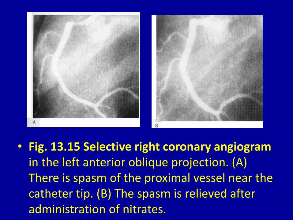
• Fig. 13.15 Selective right coronary angiogram in the left anterior oblique projection. (A) There is spasm of the proximal vessel near the catheter tip. (B) The spasm is relieved after administration of nitrates.
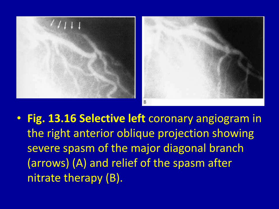
• Fig. 13.16 Selective left coronary angiogram in the right anterior oblique projection showing severe spasm of the major diagonal branch (arrows) (A) and relief of the spasm after nitrate therapy (B).

• Fig. 13.17 Selective left coronary angiogram in the left anterior oblique projection with caudocranial angulation showing constriction of the mid part of the left anterior descending artery in systole due to a 'muscle bridge' (arrows) (A); there is no constriction in the diastolic frame (B).

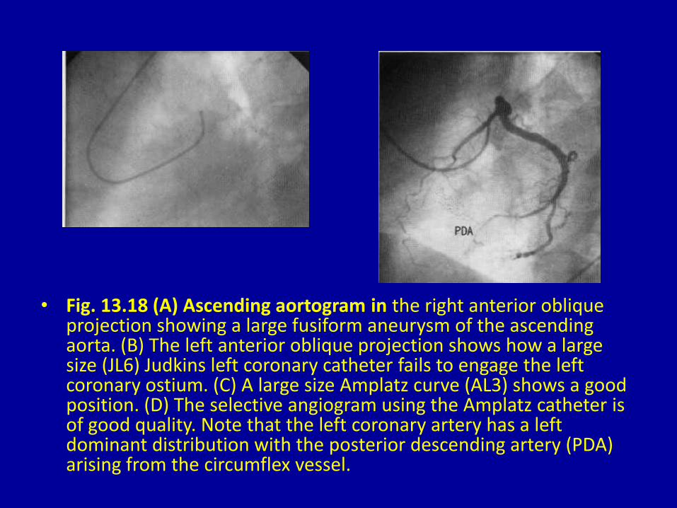
• Fig. 13.18 (A) Ascending aortogram in the right anterior oblique projection showing a large fusiform aneurysm of the ascending aorta. (B) The left anterior oblique projection shows how a large size (JL6) Judkins left coronary catheter fails to engage the left coronary ostium. (C) A large size Amplatz curve (AL3) shows a good position. (D) The selective angiogram using the Amplatz catheter is of good quality. Note that the left coronary artery has a left dominant distribution with the posterior descending artery (PDA) arising from the circumflex vessel.
• Fig. 13.18 (A) Ascending aortogram in the right anterior oblique projection showing a large fusiform aneurysm of the ascending aorta. (B) The left anterior oblique projection shows how a large size (JL6) Judkins left coronary catheter fails to engage the left coronary ostium. (C) A large size Amplatz curve (AL3) shows a good position. (D) The selective angiogram using the Amplatz catheter is of good quality. Note that the left coronary artery has a left dominant distribution with the posterior descending artery (PDA) arising from the circumflex vessel.

• Fig. 13.19 (A) Ascending aortogram in the left anterior oblique view. The patient has had surgical replacement of part of the ascending aorta (arrow) after repair of a dissecting aneurysm. (B) A long-tip Sones catheter is used to selectively cannulate the left coronary artery. The curve of the catheter clearly demonstrates the large size of the aortic root. In this case the circumflex artery is non-dominant-compare with Fig. 13.18(D).

• Fig. 13.20 (A) A saphenous vein graft from the aorta to the left anterior descending artery. The anastomosis is well seen in this lateral projection. (B) The graft shown in A seen in the right anterior oblique projection. (C) A second saphenous vein graft to the obtuse marginal vessel in the same patient-left anterior oblique projection. (D) The obtuse marginal graft shown in C in the right anterior oblique projection.

• Fig. 13.20 (A) A saphenous vein graft from the aorta to the left anterior descending artery. The anastomosis is well seen in this lateral projection. (B) The graft shown in A seen in the right anterior oblique projection. (C) A second saphenous vein graft to the obtuse marginal vessel in the same patient-left anterior oblique projection. (D) The obtuse marginal graft shown in C in the right anterior oblique projection.
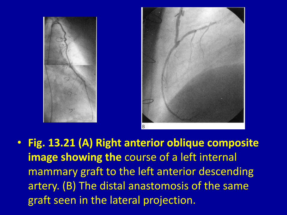
• Fig. 13.21 (A) Right anterior oblique composite image showing the course of a left internal mammary graft to the left anterior descending artery. (B) The distal anastomosis of the same graft seen in the lateral projection.
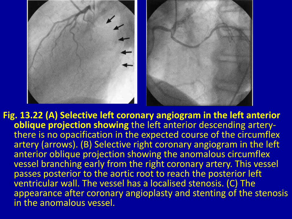
Fig. 13.22 (A) Selective left coronary angiogram in the left anterior oblique projection showing the left anterior descending artery-there is no opacification in the expected course of the circumflex artery (arrows). (B) Selective right coronary angiogram in the left anterior oblique projection showing the anomalous circumflex vessel branching early from the right coronary artery. This vessel passes posterior to the aortic root to reach the posterior left ventricular wall. The vessel has a localised stenosis. (C) The appearance after coronary angioplasty and stenting of the stenosis in the anomalous vessel.

• Fig. 13.23 (A) Selective left coronary angiogram in the left anterior oblique projection showing a recessive left coronary distribution. (B) The vessel shown in A in the right anterior oblique projection. (C) Selective right coronary angiogram in the left anterior oblique projection showing a 'single' coronary artery with a normal right coronary distribution (RCA) as well as a 'left coronary‘ vessel supplying left anterior descending and circumflex (Cx) branches. (D) The arteries shown in C seen in the right anterior oblique projection. LAD = left anterior descending artery; OM = obtuse marginal branch of the circumflex artery; PDA = posterior descending branch.

• Fig. 13.23 (A) Selective left coronary angiogram in the left anterior oblique projection showing a recessive left coronary distribution. (B) The vessel shown in A in the right anterior oblique projection. (C) Selective right coronary angiogram in the left anterior oblique projection showing a 'single' coronary artery with a normal right coronary distribution (RCA) as well as a 'left coronary‘ vessel supplying left anterior descending and circumflex (Cx) branches. (D) The arteries shown in C seen in the right anterior oblique projection. LAD = left anterior descending artery; OM = obtuse marginal branch of the circumflex artery; PDA = posterior descending branch.

• Fig. 13.24 A patient with a longstanding giant coronary artery fistula from the left coronary artery to the right atrium. (A) Aortic root injection in the left anterior oblique projection showing the tortuous proximal part of the vessel. (B) The vessel shown in A in the right anterior oblique projection. (C) A late frame in the right anterior oblique projection showing filling of the extensive distal aneurysmal portion of the vessel. (D) Selective angiogram of the normal size left anterior descending artery which arose from within the proximal part of the pathological vessel.

• Fig. 13.24 A patient with a longstanding giant coronary artery fistula from the left coronary artery to the right atrium. (A) Aortic root injection in the left anterior oblique projection showing the tortuous proximal part of the vessel. (B) The vessel shown in A in the right anterior oblique projection. (C) A late frame in the right anterior oblique projection showing filling of the extensive distal aneurysmal portion of the vessel. (D) Selective angiogram of the normal size left anterior descending artery which arose from within the proximal part of the pathological vessel.

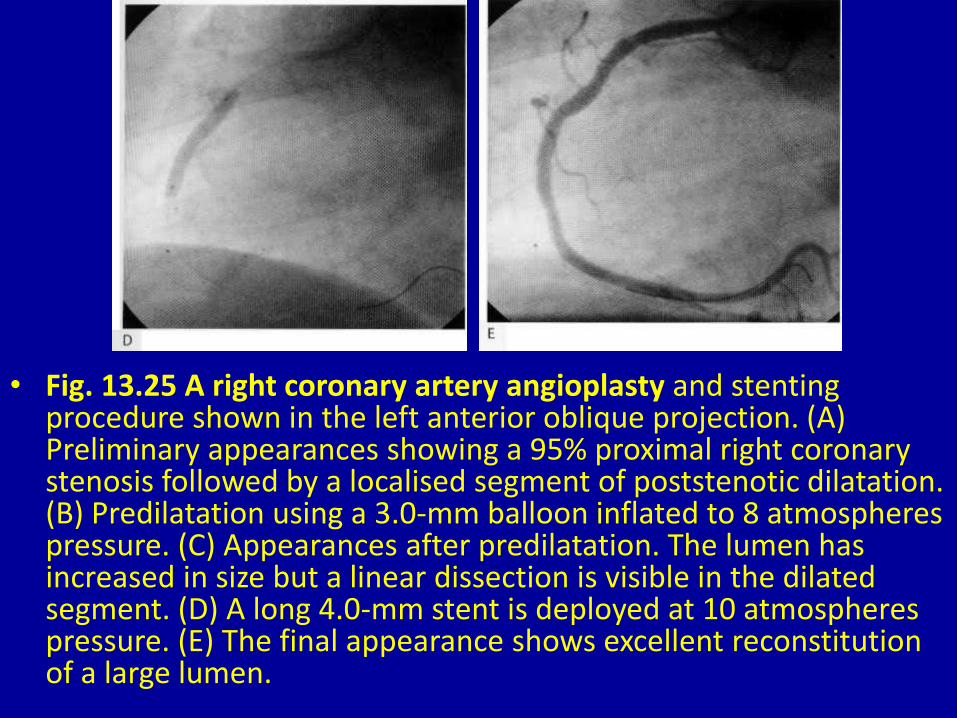
• Fig. 13.25 A right coronary artery angioplasty and stenting procedure shown in the left anterior oblique projection. (A) Preliminary appearances showing a 95% proximal right coronary stenosis followed by a localised segment of poststenotic dilatation. (B) Predilatation using a 3.0-mm balloon inflated to 8 atmospheres pressure. (C) Appearances after predilatation. The lumen has increased in size but a linear dissection is visible in the dilated segment. (D) A long 4.0-mm stent is deployed at 10 atmospheres pressure. (E) The final appearance shows excellent reconstitution of alarge lumen.
• Fig. 13.25 A right coronary artery angioplasty and stenting procedure shown in the left anterior oblique projection. (A) Preliminary appearances showing a 95% proximal right coronary stenosis followed by a localised segment of poststenotic dilatation. (B) Predilatation using a 3.0-mm balloon inflated to 8 atmospheres pressure. (C) Appearances after predilatation. The lumen has increased in size but a linear dissection is visible in the dilated segment. (D) A long 4.0-mm stent is deployed at 10 atmospheres pressure. (E) The final appearance shows excellent reconstitution of a large lumen.

• Fig. 13.26 Primary stenting procedure of a 90% stenosis in the proximal left anterior descending artery shown in the right anterior oblique projection. (A) Preliminary appearance of the stenosis. (B) Magnified view of stent positioning in the stenosis. (C) Deployment of a short 3.5-mm stent at 10 atmospheres pressure. (D) Final appearance showing full reconstitution of the lumen.

• Fig. 13.26 Primary stenting procedure of a 90% stenosis in the proximal left anterior descending artery shown in the right anterior oblique projection. (A) Preliminary appearance of the stenosis. (B) Magnified view of stent positioning in the stenosis. (C) Deployment of a short 3.5-mm stent at 10 atmospheres pressure. (D) Final appearance showing full reconstitution of the lumen.
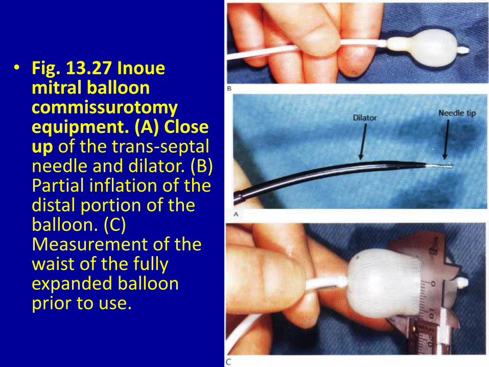
• Fig. 13.27 Inoue mitral balloon commissurotomy equipment. (A) Close up of the trans-septal needle and dilator. (B) Partial inflation of the distal portion of the balloon. (C) Measurement of the waist of the fully expanded balloon prior to use.

• Fig. 13.28 Angiographic recording of Inoue mitral valve balloon commissurotomy in the PA projection. (A) The distal portion of the balloon is inflated in the left ventricle and pulled back to the mitral orifice. (B) The fully expanded balloon is shown with the waist seated in the mitral orifice.
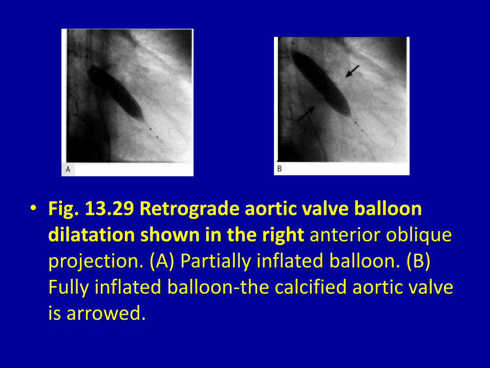
• Fig. 13.29 Retrograde aortic valve balloon dilatation shown in the right anterior oblique projection. (A) Partially inflated balloon. (B) Fully inflated balloon-the calcified aortic valve is arrowed.
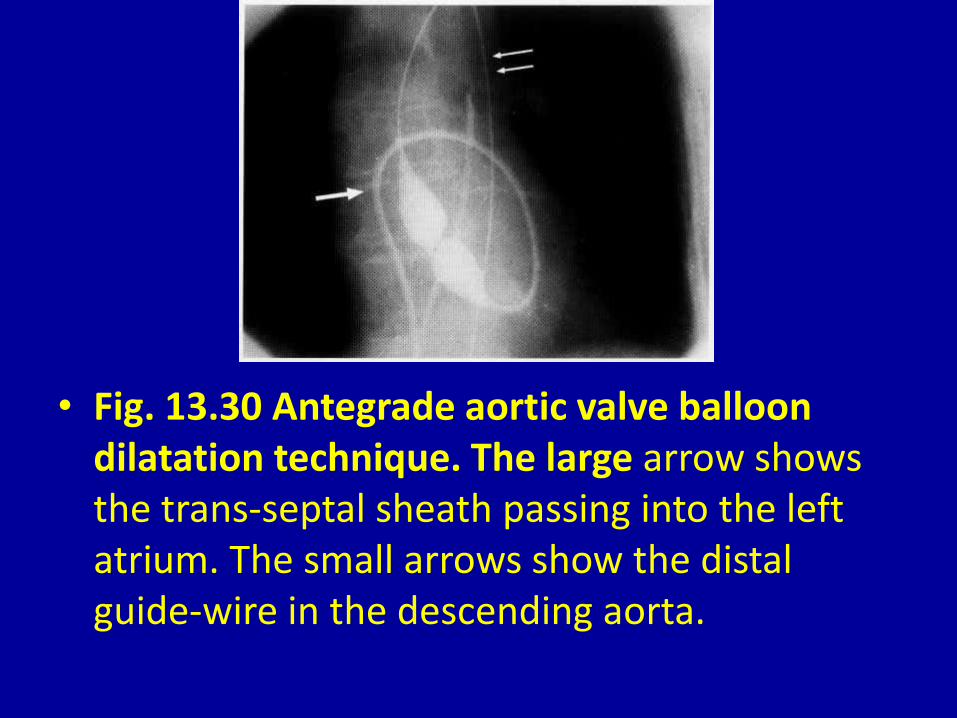
• Fig. 13.30 Antegrade aortic valve balloon dilatation technique. The large arrow shows the trans-septal sheath passing into the left atrium. The small arrows show the distal guide-wire in the descending aorta.
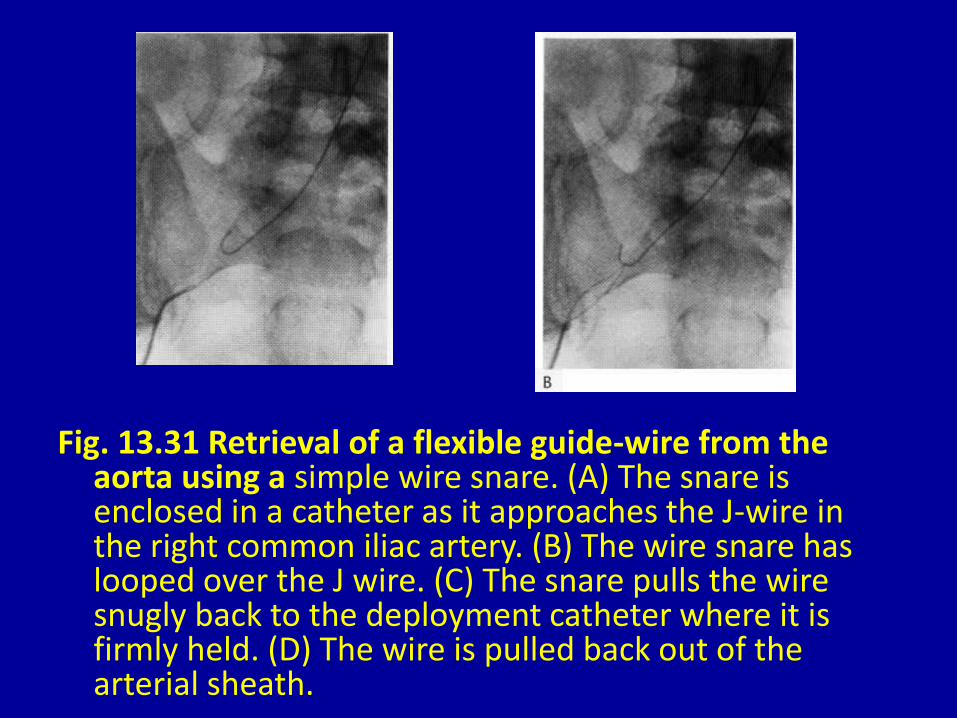
Fig. 13.31 Retrieval of a flexible guide-wire from the aorta using a simple wire snare. (A) The snare is enclosed in a catheter as it approaches the J-wire in the right common iliac artery. (B) The wire snare has looped over the J wire. (C) The snare pulls the wire snugly back to the deployment catheter where it is firmly held. (D) The wire is pulled back out of the arterial sheath.

• Fig. 13.31 Retrieval of a flexible guide-wire from the aorta using a simple wire snare. (A) The snare is enclosed in a catheter as it approaches the J-wire in the right common iliac artery. (B) The wire snare has looped over the J wire. (C) The snare pulls the wire snugly back to the deployment catheter where it is firmly held. (D) The wire is pulled back out of the arterial sheath.

• Fig. 13.32 A patient with bileaflet prosthetic mechanical valves in the mitral and tricuspid positions. The patient had progressive right heart failure. (A) Left anterior oblique pulsed acquisition showing leaflets of both valves open in diastole. (B) The systolic frame shows that the mitral leaflets ( M) have both closed but one of the tricuspid leaflets (T) remains fixed in the open position.


