129920 - Art's Cycleryvid.artscyclery.com/pdf/Cannondale Trigger User Manual.pdf · Cannondale...
38
TRIGGER 29ER & TRIGGER 26ER. OWNER’S MANUAL SUPPLEMENT. 129920
Transcript of 129920 - Art's Cycleryvid.artscyclery.com/pdf/Cannondale Trigger User Manual.pdf · Cannondale...

CANNONDALE USACycling Sports Group, Inc.172 Friendship Road, Bedford, Pennsylvania, 15522-6600, USA(Voice): 1-800-BIKE-USA (Fax): [email protected]
CANNONDALE EUROPECycling Sports Group Europe, B.V.mail: Postbus 5100visits: Hanzepoort 277570 GC, Oldenzaal, Netherlands(Voice): +41 61.4879380 (Fax): [email protected]
WARNING! READ THIS SUPPLEMENT AND YOUR CANNONDALE BICYCLE OWNER’S MANUAL. BOTH CONTAIN IMPORTANT SAFETY INFORMATION. KEEP BOTH FOR FUTURE REFERENCE.
CANNONDALE UKCycling Sports GroupVantage Way, The Fulcrum, Poole, Dorset, BH12 4NU(Voice): +44 (0)1202 732288(Fax): +44 (0)1202 [email protected]
CANNONDALE AUSTRALIACycling Sports GroupUnit 8, 31-41 Bridge RoadStanmore NSW 2048Phone: +61 (0)2 8595 4444Fax: +61 (0) 8595 [email protected]
CANNONDALE JAPANNamba Sumiso Building 9F, 4-19, Minami Horie 1-chome,Nishi-ku, Osaka 550-0015, Japan(Voice): 06-6110-9390(Fax): [email protected]
WWW.CANNONDALE.COM© 2012 Cycling Sports Group129920 (12/12)
TRIG
GER
29ER
& T
RIGG
ER 2
6ER
OW
NER’
S M
ANUA
L SU
PPLE
MEN
T
TRIGGER 29ER & TRIGGER 26ER.OWNER’S MANUAL SUPPLEMENT.
129920
This manual meets EN standards 14764, 14766, and 14781.
Vélo certifié conforme aux exigences du décret N 95-937 du 24 août 1995 norme NFR030
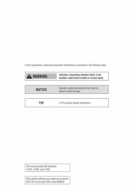
In this supplement, particularly important information is presented in the following ways:
WARNING Indicates a hazardous situation which, if not avoided, could result in death or serious injury.
NOTICE Indicates special precautions that must be taken to avoid damage.
TIP A TIP provides helpful information.
22
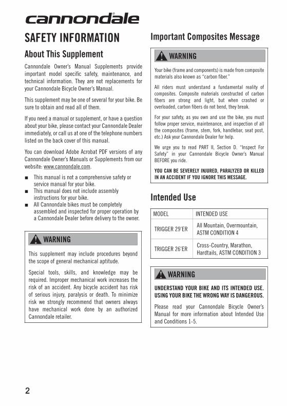
SaFETY InFORMaTIOnabout This Supplement Cannondale Owner’s Manual Supplements provide important model specific safety, maintenance, and technical information. They are not replacements for your Cannondale Bicycle Owner’s Manual.
This supplement may be one of several for your bike. Be sure to obtain and read all of them.
If you need a manual or supplement, or have a question about your bike, please contact your Cannondale Dealer immediately, or call us at one of the telephone numbers listed on the back cover of this manual.
You can download Adobe Acrobat PDF versions of any Cannondale Owner’s Manuals or Supplements from our website: www.cannondale.com.
■ This manual is not a comprehensive safety or service manual for your bike.
■ This manual does not include assembly instructions for your bike.
■ All Cannondale bikes must be completely assembled and inspected for proper operation by a Cannondale Dealer before delivery to the owner.
waRnInG
This supplement may include procedures beyond the scope of general mechanical aptitude.
Special tools, skills, and knowledge may be required. Improper mechanical work increases the risk of an accident. Any bicycle accident has risk of serious injury, paralysis or death. To minimize risk we strongly recommend that owners always have mechanical work done by an authorized Cannondale retailer.
Important Composites Message
waRnInG
Your bike (frame and components) is made from composite materials also known as “carbon fiber.”
All riders must understand a fundamental reality of composites. Composite materials constructed of carbon fibers are strong and light, but when crashed or overloaded, carbon fibers do not bend, they break.
For your safety, as you own and use the bike, you must follow proper service, maintenance, and inspection of all the composites (frame, stem, fork, handlebar, seat post, etc.) Ask your Cannondale Dealer for help.
We urge you to read PART II, Section D. “Inspect For Safety” in your Cannondale Bicycle Owner’s Manual BEFORE you ride.
YOu Can BE SEVERElY InJuRED, PaRalYZED OR KIllED In an aCCIDEnT IF YOu IGnORE THIS MESSaGE.
Intended use
MODEL INTENDED USE
TRIGGER 29’ERAll Mountain, Overmountain, ASTM CONDITION 4
TRIGGER 26’ERCross-Country, Marathon, Hardtails, ASTM CONDITION 3
waRnInG
unDERSTanD YOuR BIKE anD ITS InTEnDED uSE. uSInG YOuR BIKE THE wROnG waY IS DanGEROuS.
Please read your Cannondale Bicycle Owner’s Manual for more information about Intended Use and Conditions 1-5.
3
129920.PDF
3
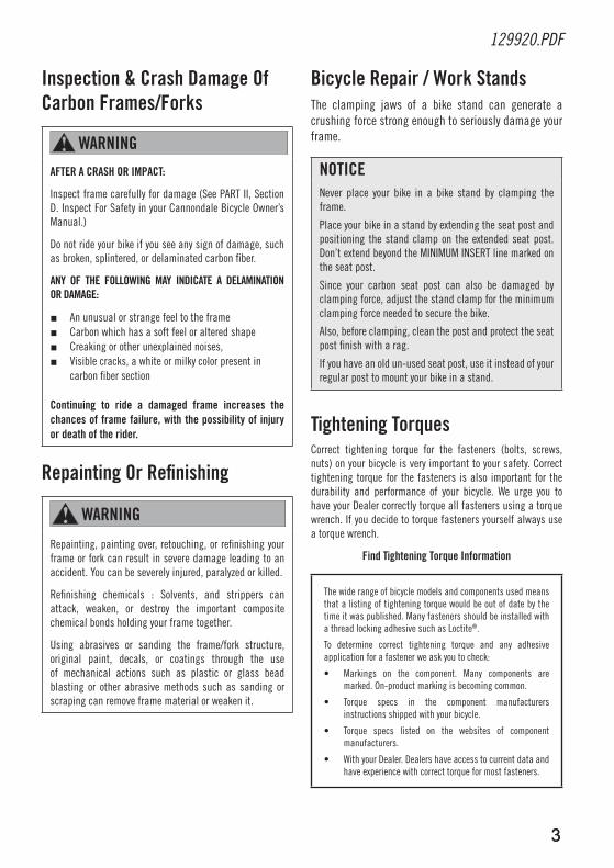
Inspection & Crash Damage Of Carbon Frames/Forks
waRnInG
aFTER a CRaSH OR IMPaCT:
Inspect frame carefully for damage (See PART II, Section D. Inspect For Safety in your Cannondale Bicycle Owner’s Manual.)
Do not ride your bike if you see any sign of damage, such as broken, splintered, or delaminated carbon fiber.
anY OF THE FOllOwInG MaY InDICaTE a DElaMInaTIOn OR DaMaGE:
■ An unusual or strange feel to the frame■ Carbon which has a soft feel or altered shape■ Creaking or other unexplained noises,■ Visible cracks, a white or milky color present in
carbon fiber section
Continuing to ride a damaged frame increases the chances of frame failure, with the possibility of injury or death of the rider.
Repainting Or Refinishing
waRnInG
Repainting, painting over, retouching, or refinishing your frame or fork can result in severe damage leading to an accident. You can be severely injured, paralyzed or killed.
Refinishing chemicals : Solvents, and strippers can attack, weaken, or destroy the important composite chemical bonds holding your frame together.
Using abrasives or sanding the frame/fork structure, original paint, decals, or coatings through the use of mechanical actions such as plastic or glass bead blasting or other abrasive methods such as sanding or scraping can remove frame material or weaken it.
Bicycle Repair / work StandsThe clamping jaws of a bike stand can generate a crushing force strong enough to seriously damage your frame.
nOTICENever place your bike in a bike stand by clamping the frame.
Place your bike in a stand by extending the seat post and positioning the stand clamp on the extended seat post. Don’t extend beyond the MINIMUM INSERT line marked on the seat post.
Since your carbon seat post can also be damaged by clamping force, adjust the stand clamp for the minimum clamping force needed to secure the bike.
Also, before clamping, clean the post and protect the seat post finish with a rag.
If you have an old un-used seat post, use it instead of your regular post to mount your bike in a stand.
Tightening TorquesCorrect tightening torque for the fasteners (bolts, screws, nuts) on your bicycle is very important to your safety. Correct tightening torque for the fasteners is also important for the durability and performance of your bicycle. We urge you to have your Dealer correctly torque all fasteners using a torque wrench. If you decide to torque fasteners yourself always use a torque wrench.
Find Tightening Torque Information
The wide range of bicycle models and components used means that a listing of tightening torque would be out of date by the time it was published. Many fasteners should be installed with a thread locking adhesive such as Loctite®.
To determine correct tightening torque and any adhesive application for a fastener we ask you to check:
• Markings on the component. Many components are marked. On-product marking is becoming common.
• Torque specs in the component manufacturers instructions shipped with your bicycle.
• Torque specs listed on the websites of component manufacturers.
• With your Dealer. Dealers have access to current data and have experience with correct torque for most fasteners.
44
water BottlesSide impacts to a water bottle or cage can result in damage threaded inserts due to the leverage on a very small area. In a crash, certainly the last thing you should be worried about is saving the threaded inserts in your frame. However, when you are storing or transporting your bike, take steps to prevent situations where a water bottle may be hit or bumped by a strong force that would cause damage. Remove bottle and cage when you are packing your bike for travel.
Periodically check the attachment of the bottle cage; tighten the cage bolts if necessary. Don’t ride with a loose bottle cage. Riding with loose cage bolts can produce a rocking motion or vibration of the attached cage. A loose cage will damage the insert and possibly lead to the inserts to pull out. It may be possible to repair a loose insert, or install another insert only if the frame is undamaged. Replacement requires the use of a special tool. If you notice damage to the threaded insert, please ask your Cannondale Dealer for help.
nOTICEwaTER BOTTlES - An impact, crash, or loose bottle cage can result in damage to your frame.
This kind of damage is not covered by the Cannondale Limited Warranty.
Building up a FramesetBefore building up a frameset, consult with your Cannondale Dealer and the component manufacturers, and discuss your riding style, ability, weight, and interest in and patience for maintenance.
Make sure the components chosen are compatible with your bike and intended for your weight and riding style.
Generally speaking, lighter weight components have shorter lives. In selecting lightweight components, you are making a trade-off, favoring the higher performance that comes with less weight over longevity. If you choose more lightweight components, you must inspect them more frequently. If you are a heavier rider or have a rough, abusive or “go for it” riding style, buy heavy duty components.
Read and follow the component manufacturers warnings and instructions.
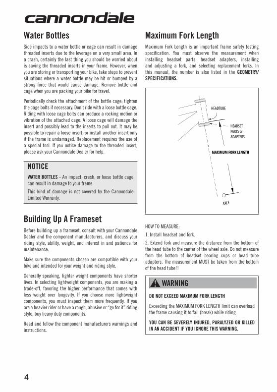
Maximum Fork lengthMaximum Fork Length is an important frame safety testing specification. You must observe the measurement when installing headset parts, headset adapters, installing and adjusting a fork, and selecting replacement forks. In this manual, the number is also listed in the GEOMETRY/SPECIFICaTIOnS.
HEADTUBE
HEADSETPARTS orADAPTERS
AXLE
MAXIMUM FORK LENGTH
HOW TO MEASURE:
1. Install headset and fork.
2. Extend fork and measure the distance from the bottom of the head tube to the center of the wheel axle. Do not measure from the bottom of headset bearing cups or head tube adapters. The measurement MUST be taken from the bottom of the head tube!!
waRnInG
DO nOT EXCEED MaXIMuM FORK lEnGTH
Exceeding the MAXIMUM FORK LENGTH limit can overload the frame causing it to fail (break) while riding.
YOu Can BE SEVERElY InJuRED, PaRalYZED OR KIllED In an aCCIDEnT IF YOu IGnORE THIS waRnInG.
5
129920.PDF
5
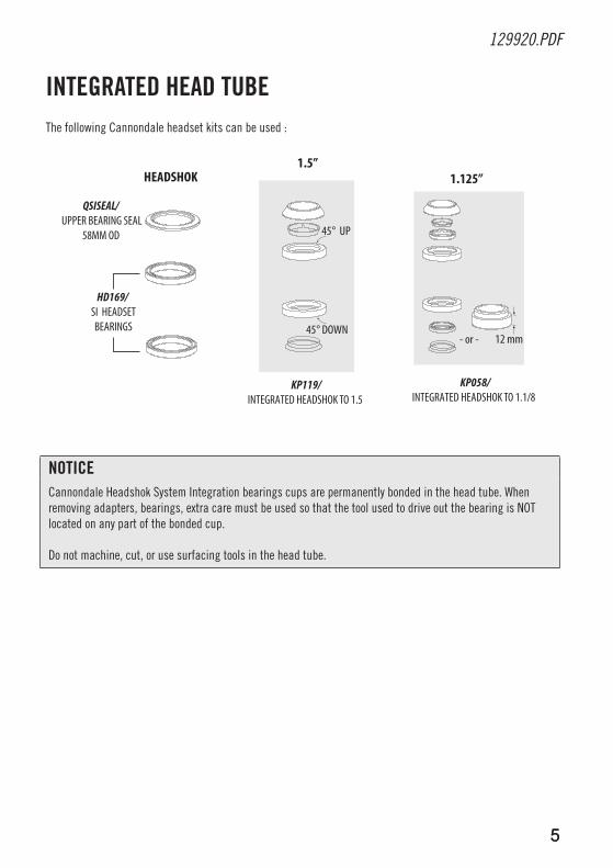
InTEGRaTED HEaD TuBEThe following Cannondale headset kits can be used :
45° UP
45° DOWN12 mm - or -
1.125”
KP119/INTEGRATED HEADSHOK TO 1.5
QSISEAL/ UPPER BEARING SEAL
58MM OD
HD169/ SI HEADSETBEARINGS
HEADSHOK1.5”
KP058/INTEGRATED HEADSHOK TO 1.1/8
nOTICECannondale Headshok System Integration bearings cups are permanently bonded in the head tube. When removing adapters, bearings, extra care must be used so that the tool used to drive out the bearing is NOT located on any part of the bonded cup.
Do not machine, cut, or use surfacing tools in the head tube.
66
a
43
1
2
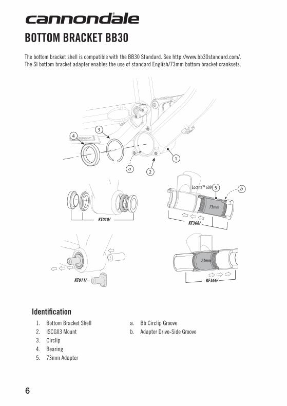
KF366/
KF368/
Loctite™ 609 b
KT010/
KT011/
73mm
73mm
5
Identification1. Bottom Bracket Shell a. Bb Circlip Groove2. ISCG03 Mount b. Adapter Drive-Side Groove3. Circlip4. Bearing5. 73mm Adapter
BOTTOM BRaCKET BB30 The bottom bracket shell is compatible with the BB30 Standard. See http://www.bb30standard.com/. The SI bottom bracket adapter enables the use of standard English/73mm bottom bracket cranksets.
7
129920.PDF
7
Bearing MaintenanceInspect bearing condition annually (at a minimum) and anytime the crankset assembly is disassembled or serviced. With the crankset removed, rotate the inner bearing race of both bearings; rotation should be smooth. No play or movement inside the shell. If the bearing is damaged, replace both bearings with new ones.
Bearing Removal/Installation (Professional Bike Mechanic Only)Remove the old bearings with the bearing removal tool KT011/.
Reinstall bearings with a headset press and tool KT010/. Clean inside of shell apply a high-quality bicycle bearing grease to the inside surface. Press bearing one at a time. Press each bearing until seated against the circlip. Following installation, apply a light coating of a high-quality bicycle bearing grease to both sides of each bearing to help repel moisture.
TIP: Unless a circlip is damaged, removal is unnecessary during bearing removal. Use a small thin-blade screw driver or pick to lift the hooked end up out of the groove and then pushing the circlip out counter-clockwise.
adapter Removal/Installation (Professional Bike Mechanic Only)To install, first remove the bearings and circlips and clean the inside of the BB shell and adapter. Use a clean lint-free shop towel dampened with alcohol. Apply Loctite™ 609 carefully to the bearing seat positions to both shell and adapter. Install the adapter with a headset press and the installation tool KF368/. Adapter groove must be located on the BB drive side. Press until the groove side face is flush with the drive side face of shell. Allow at least 12 hours (at 72°F) for the Loctite to cure before installing the standard bottom bracket crankset. Follow Loctite Technical Data Sheet http://tds.loctite.com/tds5/docs/609-EN.PDF
To remove, use tool KF366/ with a headset bearing press with tool arrangement as shown. Following removal, it will be necessary to clean all remaining Loctite residue with a before reinstalling the Si circlips and bearings. Use Loctite 768. Use a dental pick to remove any adhesive from the grooves. For Loctite clean-up instructions : http://tds.loctite.com/
nOTICEBEARINGS - Frequent or routine renewal of undamaged bearings is not recommended. Repeated removal and reinstallation can damage the inside BB shell surfaces resulting in poor bearing fit. Do not face, mill or machine the bottom bracket shell for any reason. Doing so can result in serious damage and possibly a ruined bike frame.
ADAPTERS - Use only adapters/tool recommended by Cannondale. Other available adapters /tools may cause damage. See Replacement Parts. An adapter isn’t a “repair” part, so the BB shell must be in good condition. Repeated removal and reinstallation of an adapter, or improper tools can cause damage. Therefore it is not recommended.
Loctite 609 - Prolonged contact with the frame finish may result in discoloration or damage. Be sure to immediately wipe up any spills and remove any compound in contact with the painted surfaces.
Do not cut, face, or use abrasives to clean the inside if the BB shell.
We strongly recommend that these procedures be performed by an Authorized Cannondale Dealer. Damage caused by improper installation/removal is not covered under your warranty.
88
1
8
13
9
9
16
17
7
2
43
5
14
18
. 5”
15
11
20
19
10
8
6
12
5-10 InLbs
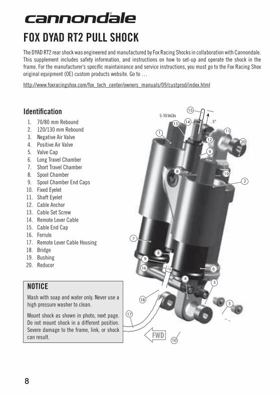
FOX DYaD RT2 Pull SHOCKThe DYAD RT2 rear shock was engineered and manufactured by Fox Racing Shocks in collaboration with Cannondale. This supplement includes safety information, and instructions on how to set-up and operate the shock in the frame. For the manufacturer’s specifi c maintainance and service instructions, you must go to the Fox Racing Shox original equipment (OE) custom products website. Go to …
http://www.foxracingshox.com/fox_tech_center/owners_manuals/09/custprod/index.html
Identifi cation1. 70/80 mm Rebound2. 120/130 mm Rebound3. Negative Air Valve4. Positive Air Valve5. Valve Cap6. Long Travel Chamber7. Short Travel Chamber8. Spool Chamber9. Spool Chamber End Caps
10. Fixed Eyelet11. Shaft Eyelet12. Cable Anchor13. Cable Set Screw14. Remote Lever Cable15. Cable End Cap16. Ferrule17. Remote Lever Cable Housing18. Bridge19. Bushing20. Reducer
nOTICEWash with soap and water only. Never use a high pressure washer to clean.
Mount shock as shown in photo, next page. Do not mount shock in a different position. Severe damage to the frame, link, or shock can result.
9
129920.PDF
9
Maintenance & Service Information
waRnInG
HIGH-PRESSuRE HaZaRD - Do not open, disassemble, modify, or attempt to perform internal service to the shock. The DYAD RT2 shock is not user serviceable. Never attempt to remove the spool chamber end caps for any reason! Attempting to perform any mechanical service procedure on this shock can potentially result in serious injury or death. Remote lever cable installation must be performed by a professional bike mechanic.
All service and repair must only be performed by FOX Racing Shox or an FOX Authorized Service Center.
For more informatiomn contact: http://www.foxracingshox.com/fox/contact
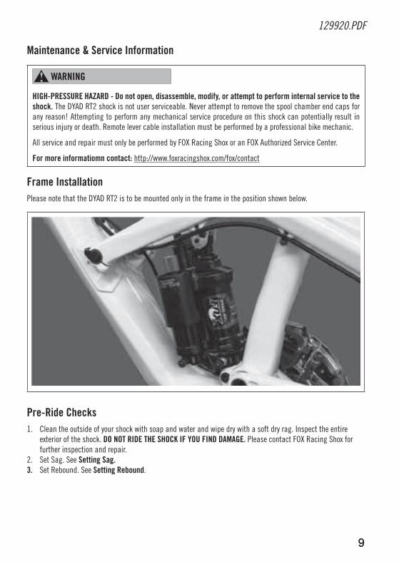
Frame InstallationPlease note that the DYAD RT2 is to be mounted only in the frame in the position shown below.
Pre-Ride Checks1. Clean the outside of your shock with soap and water and wipe dry with a soft dry rag. Inspect the entire
exterior of the shock. DO nOT RIDE THE SHOCK IF YOu FInD DaMaGE. Please contact FOX Racing Shox for further inspection and repair.
2. Set Sag. See Setting Sag.3. Set Rebound. See Setting Rebound.
1010
FLOW mode(long travel)120/130 mm
FWD
ELEVATE mode (short travel)
70/80 mm
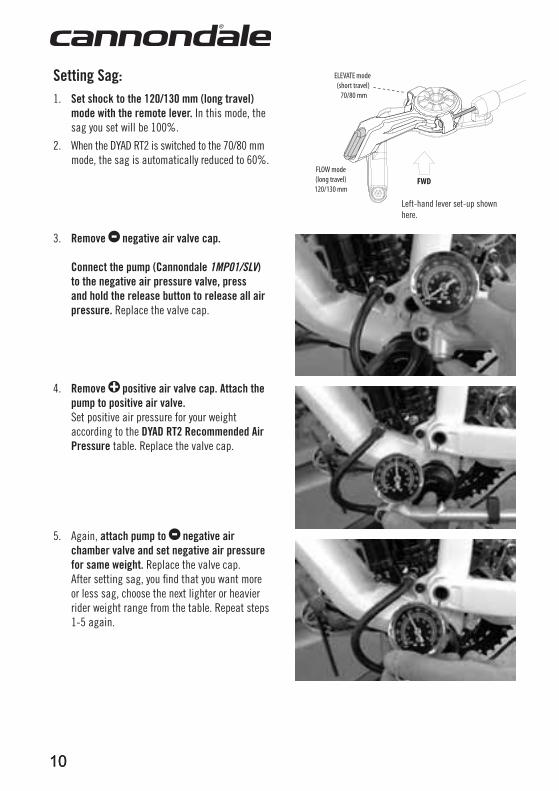
Setting Sag:1. Set shock to the 120/130 mm (long travel)
mode with the remote lever. In this mode, the sag you set will be 100%.
2. When the DYAD RT2 is switched to the 70/80 mm mode, the sag is automatically reduced to 60%.
3. Remove negative air valve cap. Connect the pump (Cannondale 1MP01/SLV) to the negative air pressure valve, press and hold the release button to release all air pressure. Replace the valve cap.
4. Remove positive air valve cap. attach the pump to positive air valve. Set positive air pressure for your weight according to the DYaD RT2 Recommended air Pressure table. Replace the valve cap.
5. Again, attach pump to negative air chamber valve and set negative air pressure for same weight. Replace the valve cap.
After setting sag, you find that you want more or less sag, choose the next lighter or heavier rider weight range from the table. Repeat steps 1-5 again.
Left-hand lever set-up shown here.
11
129920.PDF
11
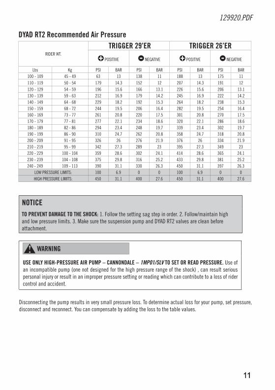
nOTICETO PREVEnT DaMaGE TO THE SHOCK: 1. Follow the setting sag step in order. 2. Follow/maintain high and low pressure limits. 3. Make sure the suspension pump and DYAD RT2 valves are clean before attachment.
waRnInG
uSE OnlY HIGH-PRESSuRE aIR PuMP – CannOnDalE – 1MP01/SLV TO SET OR REaD PRESSuRE. Use of an incompatible pump (one not designed for the high pressure range of the shock) , can result serious personal injury or result in an improper pressure setting or reading which can contribute to a loss of rider control and accident.
Disconnecting the pump results in very small pressure loss. To determine actual loss for your pump, set pressure, disconnect and reconnect. You can compensate by adding the loss to the table values.
DYaD RT2 Recommended air Pressure
RIDER WT.
TRIGGER 29’ER TRIGGER 26’ER
POSITIVE NEGATIVE POSITIVE NEGATIVE
Lbs Kg PSI BAR PSI BAR PSI BAR PSI BAR100 - 109 45 - 49 63 13 138 11 188 13 175 11110 - 119 50 - 54 179 14.3 152 12 207 14.3 191 12120 - 129 54 - 59 196 15.6 166 13.1 226 15.6 206 13.1130 - 139 59 - 63 212 16.9 179 14.2 245 16.9 222 14.2140 - 149 64 - 68 229 18.2 192 15.3 264 18.2 238 15.3150 - 159 68 - 72 244 19.5 206 16.4 282 19.5 254 16.4160 - 169 73 - 77 261 20.8 220 17.5 301 20.8 270 17.5170 - 179 77 - 81 277 22.1 234 18.6 320 22.1 286 18.6180 - 189 82 - 86 294 23.4 248 19.7 339 23.4 302 19.7190 - 199 86 - 90 310 24.7 262 20.8 358 24.7 318 20.8200 - 209 91 - 95 326 26 276 21.9 376 26 334 21.9210 - 219 95 - 99 342 27.3 289 23 395 27.3 349 23220 - 229 100 - 104 359 28.6 302 24.1 414 28.6 365 24.1230 - 239 104 - 108 375 29.8 316 25.2 433 29.8 381 25.2240 - 249 109 - 113 390 31.1 330 26.3 450 31.1 397 26.3
LOW PRESSURE LIMITS: 100 6.9 0 0 100 6.9 0 0HIGH PRESSURE LIMITS: 450 31.1 400 27.6 450 31.1 400 27.6
1212
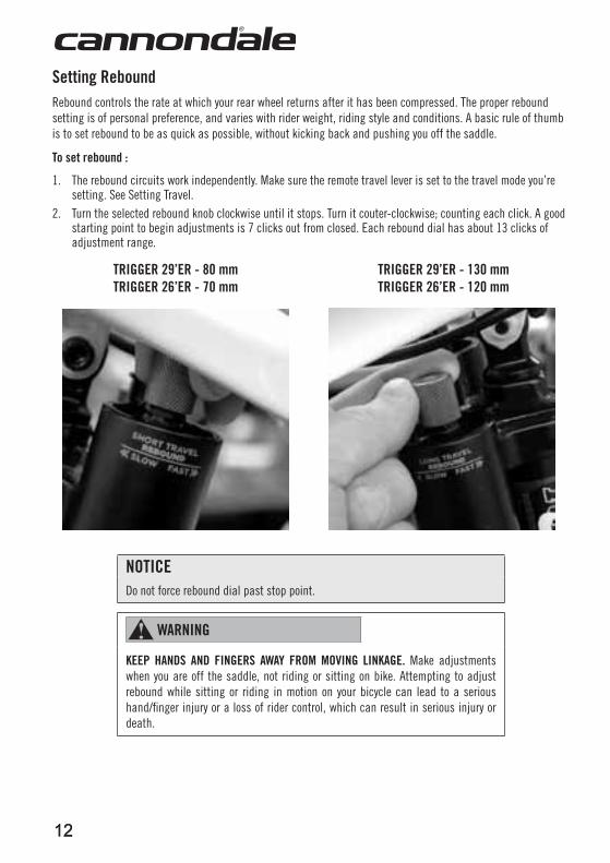
Setting ReboundRebound controls the rate at which your rear wheel returns after it has been compressed. The proper rebound setting is of personal preference, and varies with rider weight, riding style and conditions. A basic rule of thumb is to set rebound to be as quick as possible, without kicking back and pushing you off the saddle.
To set rebound :
1. The rebound circuits work independently. Make sure the remote travel lever is set to the travel mode you’re setting. See Setting Travel.
2. Turn the selected rebound knob clockwise until it stops. Turn it couter-clockwise; counting each click. A good starting point to begin adjustments is 7 clicks out from closed. Each rebound dial has about 13 clicks of adjustment range.
TRIGGER 29’ER - 80 mmTRIGGER 26’ER - 70 mm
TRIGGER 29’ER - 130 mm TRIGGER 26’ER - 120 mm
nOTICEDo not force rebound dial past stop point.
waRnInG
KEEP HanDS anD FInGERS awaY FROM MOVInG lInKaGE. Make adjustments when you are off the saddle, not riding or sitting on bike. Attempting to adjust rebound while sitting or riding in motion on your bicycle can lead to a serious hand/finger injury or a loss of rider control, which can result in serious injury or death.
13
129920.PDF
13
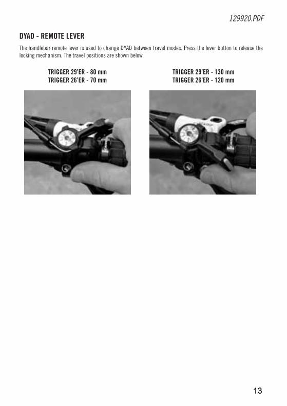
DYaD - REMOTE lEVER The handlebar remote lever is used to change DYAD between travel modes. Press the lever button to release the locking mechanism. The travel positions are shown below.
TRIGGER 29’ER - 80 mmTRIGGER 26’ER - 70 mm
TRIGGER 29’ER - 130 mm TRIGGER 26’ER - 120 mm
1414
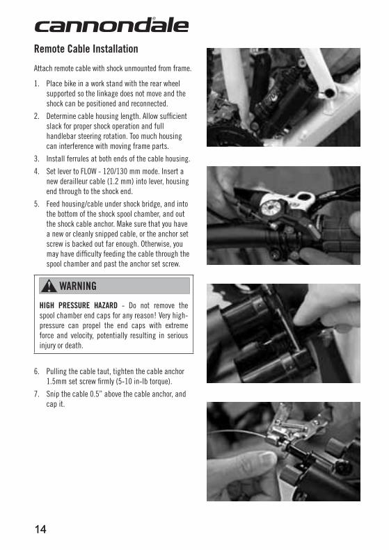
Remote Cable Installation
Attach remote cable with shock unmounted from frame.
1. Place bike in a work stand with the rear wheel supported so the linkage does not move and the shock can be positioned and reconnected.
2. Determine cable housing length. Allow sufficient slack for proper shock operation and full handlebar steering rotation. Too much housing can interference with moving frame parts.
3. Install ferrules at both ends of the cable housing.
4. Set lever to FLOW - 120/130 mm mode. Insert a new derailleur cable (1.2 mm) into lever, housing end through to the shock end.
5. Feed housing/cable under shock bridge, and into the bottom of the shock spool chamber, and out the shock cable anchor. Make sure that you have a new or cleanly snipped cable, or the anchor set screw is backed out far enough. Otherwise, you may have difficulty feeding the cable through the spool chamber and past the anchor set screw.
waRnInG
HIGH PRESSuRE HaZaRD - Do not remove the spool chamber end caps for any reason! Very high-pressure can propel the end caps with extreme force and velocity, potentially resulting in serious injury or death.
6. Pulling the cable taut, tighten the cable anchor 1.5mm set screw firmly (5-10 in-lb torque).
7. Snip the cable 0.5” above the cable anchor, and cap it.
15
129920.PDF
15
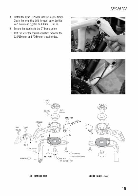
lEFT HanDlEBaR RIGHT HanDlEBaR
8. Install the Dyad RT2 back into the bicycle frame. Clean the mounting bolt threads, apply Loctite 242 (blue) and tighten to 8.0 Nm, 71 InLbs.
9. Secure the housing to the DT frame guide.
10. Test the lever for normal operation between the 120/130 mm and 70/80 mm travel modes.
7
1
9
11
6
810
2 4
3
12
NLG1-2
NLG1-2(O.D. only)
Pin
2.5 Nm, Loctite 242 (blue)
5 Nm, Loctite 262 (red)
SFHS M3X6
SFHS M6X8
CABLE STOP
BUSHING
TOP NUT
LEVER MAIN
SPRING
CLAMP BRACKET
LEVERRELEASE
SHCS M3X10
Pin
align
Slot
BASE PLATE
cable to shock
1616
35 mm
5 mm
4 mm
1
2 13
14
12
13
1
600mm SRAM650mm Shimano
155mm
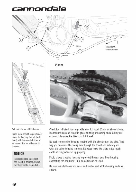
Note orientation of DT clamps.
Small plate should be positioned under the housing (parallel with lines) with the rounded sides up as shown. It is not side-specifi c, however.
nOTICEIncorrect clamp placement can result in damage. Do not over-tighten the clamp bolts.
Check for suffi cient housing cable loop. Its about 35mm as shown above. Inadequate loop can result in ghost shifting or housing ends pulling out of down tube when the bike is at full travel.
Its best to determine housing lengths with the shock out of the bike. That way you can move the swing arm through the travel and actually see what the cable housing is doing. It always looks like there is too much cable housing when set up properly.
Photo shows crossing housing to prevent the rear derailleur housing contacting the chainring. Or, a cable tie can be used.
Be sure to install nose end seals and rubber seal at the housing ends as shown.
17
129920.PDF
17
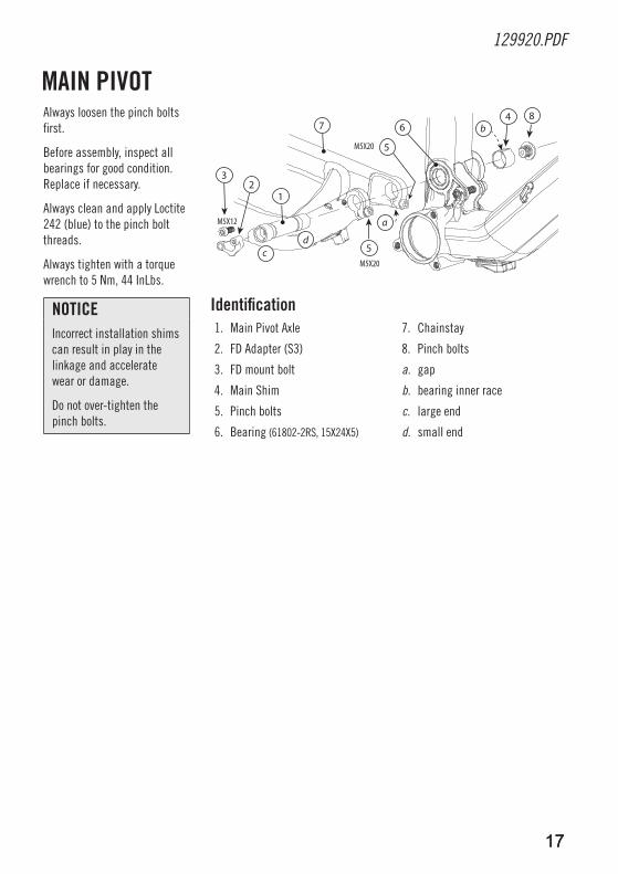
Always loosen the pinch bolts first.
Before assembly, inspect all bearings for good condition. Replace if necessary.
Always clean and apply Loctite 242 (blue) to the pinch bolt threads.
Always tighten with a torque wrench to 5 Nm, 44 InLbs.
MaIn PIVOT
nOTICEIncorrect installation shims can result in play in the linkage and accelerate wear or damage.
Do not over-tighten the pinch bolts.
M5X20
1
64
b8
M5X20
5
a
5
23
cd
M5X12
7
Identification1. Main Pivot Axle 7. Chainstay
2. FD Adapter (S3) 8. Pinch bolts
3. FD mount bolt a. gap
4. Main Shim b. bearing inner race
5. Pinch bolts c. large end
6. Bearing (61802-2RS, 15X24X5) d. small end
1818
aBOuT THIS SuPPlEMEnTThis supplement includes information for the proper installation and set up of XFuSIOn shocks in the following Cannondale models: TRIGGER 29’ER allOY and both JEKYll and SCaRlET. In addition to this supplement, follow the owner’s manual supplement infor-mation for your specifi c bike and the XFuSIOn owner’s manual.
Cannondale supplements : http://www.cannondale.com/manuals/
XFUSION manuals: http://www.xfusionshox.com/
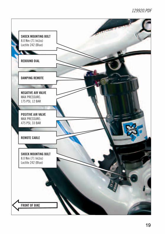
MOunTInG THE SHOCK In THE FRaMEInstall the shock in the frame with the remote assembly facing forward as shown. Apply Loctite 242 (blue) and tighten with a good torque wrench. nOTICE: Incorrect shock installation can result in serious frame damage.
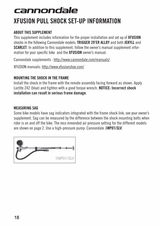
MEaSuRInG SaGSome bike models have sag indicators integrated with the frame shock link; see your owner’s supplement. Sag can be measured by the difference between the shock mounting bolts when rider is on and off the bike. The reco mmended air pressure setting for the different models are shown on page 2. Use a high-pressure pump: Cannondale 1MP01/SLV.
1MP01/SLV1MP01/SLV
XFuSIOn Pull SHOCK SET-uP InFORMaTIOn
19
129920.PDF
19
REBOunD DIal
DaMPInG REMOTE
nEGaTIVE aIR ValVEMAX PRESSURE: 175 PSI, 12 BAR
POSITIVE aIR ValVEMAX PRESSURE: 475 PSI, 33 BAR
SHOCK MOunTInG BOlT8.0 Nm (71 InLbs)Loctite 242 (Blue)
SHOCK MOunTInG BOlT8.0 Nm (71 InLbs)Loctite 242 (Blue)
REMOTE CaBlE
FROnT OF BIKE

2020
Press the small top button to release the lever. When the remote lever is uP, the shock is OPEn.
Press the remote lever DOwn until it locks to change the shock to FIRM.
The handlebar remote changes the shock performance between “OPEN” and “FIRM”. See the illustrations below.
XFuSIOn Pull SHOCK HanDlEBaR REMOTE
21
129920.PDF
21
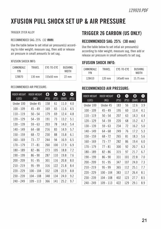
TRIGGER 29’ER ALLOY
RECOMMENDED SAG: 25% (32 mm)
Use the table below to set intial air pressure(s) accord-ing to rider weight; measure sag, then add or release air pressure in small amounts to set sag.
XFUSION SHOCK INFO:
CANNONDALE P/N
TRAVEL EYE-TO-EYE BUSHING WIDTH
128870 130 mm 155x50 mm 22 mm
RECOMMENDED AIR PRESSURE:
RIDER WEIGHT(LBS)
RIDER WEIGHT(KG)
(PSI) (PSI)
(BAR) (PSI)
Under 100 Under 45 158 61 11.0 4.0
100 - 109 45 - 49 169 65 11.6 4.5
110 - 119 50 - 54 179 69 12.4 4.8
120 - 129 54 - 59 191 73 13.2 5.1
130 - 139 59 - 63 203 78 14.0 5.4
140 - 149 64 - 68 216 83 14.9 5.7
150 - 159 68 - 72 230 88 15.8 6.1
160 - 169 73 - 77 244 94 16.9 6.5
170 - 179 77 - 81 260 100 17.9 6.9
180 - 189 82 - 86 273 105 18.8 7.2
190 - 199 86 - 90 287 110 19.8 7.6
200 - 209 91 - 95 301 116 20.8 8.0
210 - 219 95 - 99 316 122 21.8 8.4
220 - 229 100 - 104 332 128 22.9 8.8
230 - 239 104 - 108 348 134 24.0 9.2
240 - 249 109 - 113 366 141 25.2 9.7
XFuSIOn Pull SHOCK SET uP & aIR PRESSuRE
TRIGGER 26 CaRBOn (uS OnlY)RECOMMEnDED SaG: 25% (30 mm)Use the table below to set intial air pressure(s) according to rider weight; measure sag, then add or release air pressure in small amounts to set sag.
XFuSIOn SHOCK InFO:CANNONDALE
P/NTRAVEL EYE-TO-EYE BUSHING
WIDTH
128410 120 mm 145x40 mm 15.75 mm
RECOMMEnDED aIR PRESSuRE:
RIDER WEIGHT(LBS)
RIDER WEIGHT(KG)
(PSI) (PSI)
(BAR) (PSI)
Under 100 Under 45 183 56 12.6 3.9
100 - 109 45 - 49 195 60 13.4 4.1
110 - 119 50 - 54 207 63 14.3 4.4
120 - 129 54 - 59 220 68 15.2 4.7
130 - 139 59 - 63 234 72 16.2 5.0
140 - 149 64 - 68 249 76 17.2 5.3
150 - 159 68 - 72 265 81 18.3 5.6
160 - 169 73 - 77 282 86 19.4 6.0
170 - 179 77 - 81 300 92 20.7 6.3
180 - 189 82 - 86 315 97 21.7 6.7
190 - 199 86 - 90 331 101 22.8 7.0
200 - 209 91 - 95 347 107 24.0 7.3
210 - 219 95 - 99 365 112 25.1 7.7
220 - 229 100 - 104 383 117 26.4 8.1
230 - 239 104 - 108 402 123 27.7 8.5
240 - 249 109 - 113 422 129 29.1 8.9
2222
6
8 1
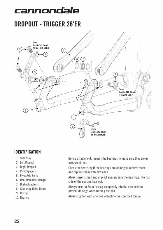
M3X10Loctite 242 (blue)2.5 Nm (22 InLbs)
5mmLoctite 242 (blue)7 Nm (62 InLbs)
5mmLoctite 242 (blue)10 Nm (88.5 InLbs)
55
4
4
2
3
7
109
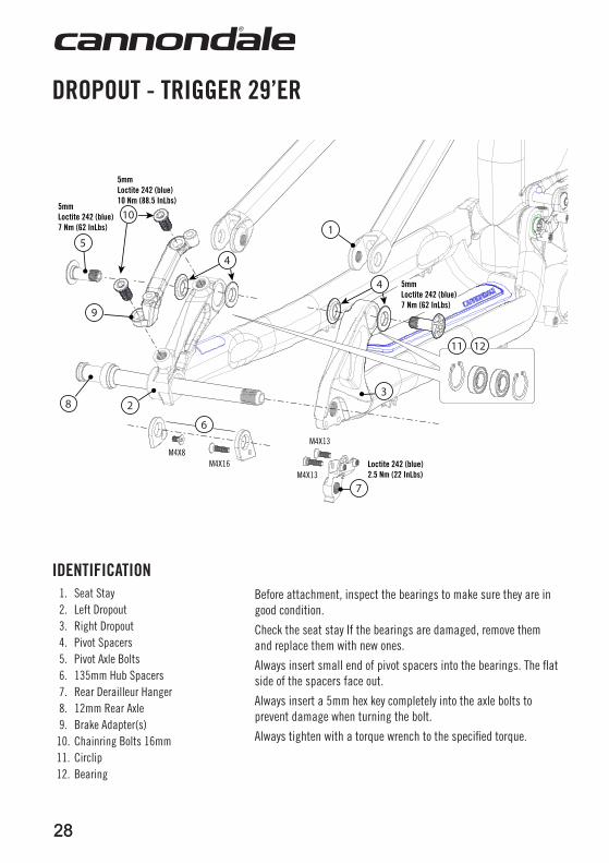
DROPOuT - TRIGGER 26’ER
IDEnTIFICaTIOn1. Seat Stay2. Left Dropout3. Right Dropout4. Pivot Spacers5. Pivot Axle Bolts6. Rear Derailleur Hanger7. Brake Adapter(s)8. Chainring Bolts 16mm9. Circlip
10. Bearing
Before attachment, inspect the bearings to make sure they are in good condition.
Check the seat stay If the bearings are damaged, remove them and replace them with new ones.
Always insert small end of pivot spacers into the bearings. The flat side of the spacers face out.
Always insert a 5mm hex key completely into the axle bolts to prevent damage when turning the bolt.
Always tighten with a torque wrench to the specified torque.
23
129920.PDF
25%
1
c
d2
4
b7
d
c
3
6
M6X30
6
M6X30
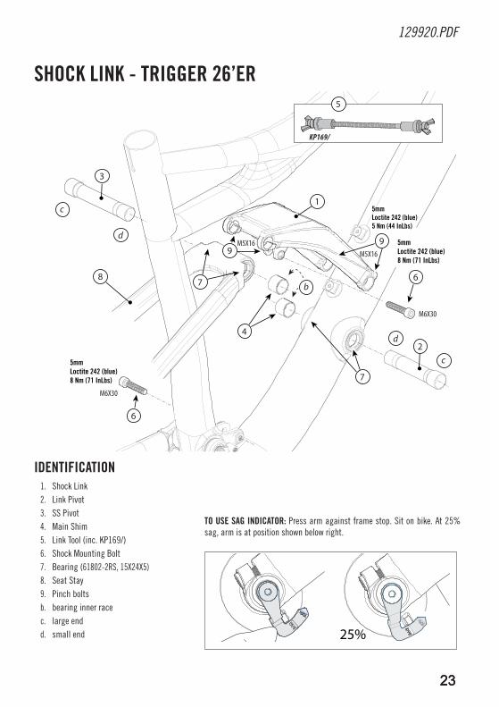
5mmLoctite 242 (blue)8 Nm (71 InLbs)
M5X16
5mmLoctite 242 (blue)5 Nm (44 InLbs)
9M5X16
7
9
5
KP169/
8
5mmLoctite 242 (blue)8 Nm (71 InLbs)
2323
SHOCK lInK - TRIGGER 26’ER
IDEnTIFICaTIOn1. Shock Link2. Link Pivot3. SS Pivot4. Main Shim5. Link Tool (inc. KP169/)6. Shock Mounting Bolt7. Bearing (61802-2RS, 15X24X5)8. Seat Stay9. Pinch boltsb. bearing inner racec. large endd. small end
TO uSE SaG InDICaTOR: Press arm against frame stop. Sit on bike. At 25% sag, arm is at position shown below right.
24
KP252/
A
B
B
KP175/KP176/KP177/KP178/
KP187/
KP240/
A
A
B
A
M6X30
KP181/M6X30
KP238/
M5X16
M5X16
M5X20
M5X20
M5X12
1MP01/SLV
KP169/
KP121/
KP237/
KP180/
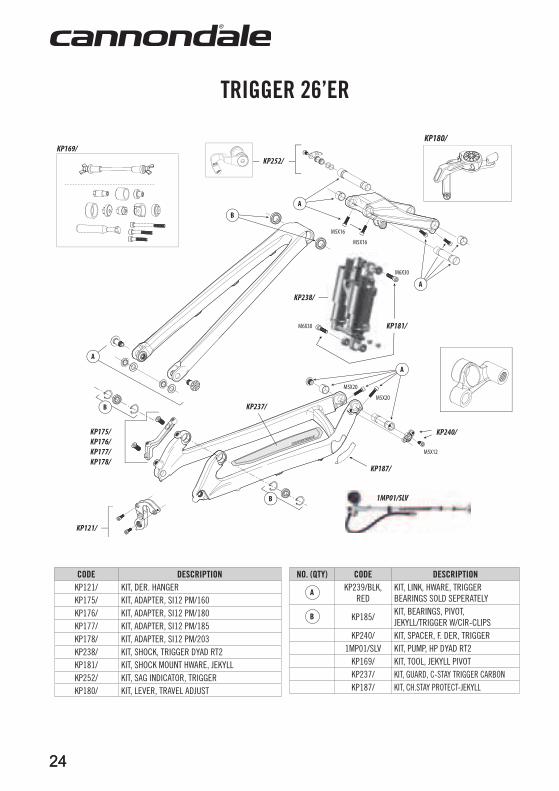
CODE DESCRIPTIOnKP121/ KIT, DER. HANGERKP175/ KIT, ADAPTER, SI12 PM/160KP176/ KIT, ADAPTER, SI12 PM/180KP177/ KIT, ADAPTER, SI12 PM/185KP178/ KIT, ADAPTER, SI12 PM/203KP238/ KIT, SHOCK, TRIGGER DYAD RT2KP181/ KIT, SHOCK MOUNT HWARE, JEKYLLKP252/ KIT, SAG INDICATOR, TRIGGERKP180/ KIT, LEVER, TRAVEL ADJUST
nO. (QTY) CODE DESCRIPTIOnKP239/BLK,
REDKIT, LINK, HWARE, TRIGGER BEARINGS SOLD SEPERATELY
KP185/KIT, BEARINGS, PIVOT, JEKYLL/TRIGGER W/CIR-CLIPS
KP240/ KIT, SPACER, F. DER, TRIGGER1MP01/SLV KIT, PUMP, HP DYAD RT2
KP169/ KIT, TOOL, JEKYLL PIVOTKP237/ KIT, GUARD, C-STAY TRIGGER CARBONKP187/ KIT, CH.STAY PROTECT-JEKYLL
TRIGGER 26’ER
24
25
129920.PDF
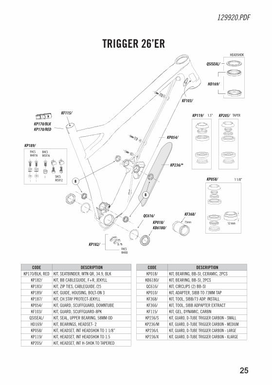
KP236/*
KP054/
B
B
QSISEAL/
12 mm
KF103/
KP058/
KP119/
KP182/
QC616/ KP018/KB6180/
KF368/
KP189/
KP170/BLKKP170/RED
73mm
KF115/
HD169/
HEADSHOK
1 1/8”
1.5”
BHCSM5X16
FHCSM4X16
FHCSM4X8
SHCSM5X12
KP205/ TAPER
CODE DESCRIPTIOnKP170/BLK, RED KIT, SEATBINDER, MTN QR, 34.9, BLK
KP182/ KIT, BB CABLEGUIDE, F+R, JEKYLLKP183/ KIT, ZIP TIES, CABLEGUIDE /25KP189/ KIT, GUIDE, HOUSING, BOLT-ON 3 KP187/ KIT, CH.STAY PROTECT-JEKYLLKP054/ KIT, GUARD, SCUFFGUARD, DOWNTUBEKF103/ KIT, GUARD, SCUFFGUARD-8PK
QSISEAL/ KIT, SEAL, UPPER BEARING, 58MM ODHD169/ KIT, BEARINGS, HEADSET- 2 KP058/ KIT, HEADSET, INT HEADSHOK TO 1 1/8”KP119/ KIT, HEADSET, INT HEADSHOK TO 1.5 KP205/ KIT, HEADSET, INT H-SHOK TO TAPERED
CODE DESCRIPTIOnKP018/ KIT, BEARING, BB-SI, CERAMIC, 2PCS
KB6180/ KIT, BEARING, BB-SI, 2PCS QC616/ KIT, CIRCLIPS (2) BB-SI KP010/ KIT, ADAPTER, SIBB TO 73MM TAPKF368/ KIT, TOOL, SIBB/73 ADP. INSTALL KF366/ KIT, TOOL, SIBB ADPAPTER EXTRACT KF115/ KIT, GEL, DYNAMIC, CARBN
KP236/S KIT, GUARD, D-TUBE TRIGGER CARBON - SMALLKP236/M KIT, GUARD, D-TUBE TRIGGER CARBON - MEDIUMKP236/L KIT, GUARD, D-TUBE TRIGGER CARBON - LARGEKP236/X KIT, GUARD, D-TUBE TRIGGER CARBON - XLARGE
TRIGGER 26’ER
25
2626
A
B
K
P
HI
J
F
LM
F
G
E
C
O
ASTM CONDITION 3XC RACING
ASTM F2043
For rough o�-road ridingand jumps less
than 24” (61 cm)
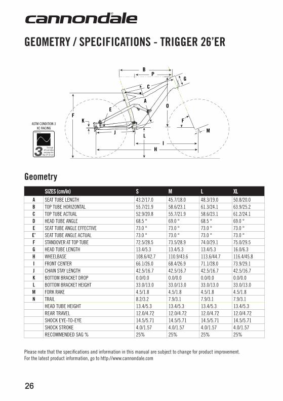
GEOMETRY / SPECIFICaTIOnS - TRIGGER 26’ER
GeometrySIZES (cm/in) S M l Xl
a SEAT TUBE LENGTH 43.2/17.0 45.7/18.0 48.3/19.0 50.8/20.0B TOP TUBE HORIZONTAL 55.7/21.9 58.6/23.1 61.3/24.1 63.9/25.2C TOP TUBE ACTUAL 52.9/20.8 55.7/21.9 58.6/23.1 61.2/24.1D HEAD TUBE ANGLE 68.5 ° 69.0 ° 68.5 ° 69.0 °E SEAT TUBE ANGLE EFFECTIVE 73.0 ° 73.0 ° 73.0 ° 73.0 °E’ SEAT TUBE ANGLE ACTUAL 73.0 ° 73.0 ° 73.0 ° 73.0 °F STANDOVER AT TOP TUBE 72.5/28.5 73.5/28.9 74.0/29.1 75.0/29.5G HEAD TUBE LENGTH 13.4/5.3 13.4/5.3 13.4/5.3 16.0/6.3H WHEELBASE 108.6/42.7 110.9/43.6 113.6/44.7 116.4/45.8I FRONT CENTER 66.1/26.0 68.4/26.9 71.1/28.0 73.9/29.1J CHAIN STAY LENGTH 42.5/16.7 42.5/16.7 42.5/16.7 42.5/16.7K BOTTOM BRACKET DROP 0.0/0.0 0.0/0.0 0.0/0.0 0.0/0.0l BOTTOM BRACKET HEIGHT 33.0/13.0 33.0/13.0 33.0/13.0 33.0/13.0M FORK RAKE 4.5/1.8 4.5/1.8 4.5/1.8 4.5/1.8n TRAIL 8.2/3.2 7.9/3.1 7.9/3.1 7.9/3.1
HEAD TUBE HEIGHT 13.4/5.3 13.4/5.3 13.4/5.3 13.4/5.3REAR TRAVEL 12.0/4.72 12.0/4.72 12.0/4.72 12.0/4.72SHOCK EYE-TO-EYE 14.5/5.71 14.5/5.71 14.5/5.71 14.5/5.71SHOCK STROKE 4.0/1.57 4.0/1.57 4.0/1.57 4.0/1.57RECOMMENDED SAG % 25% 25% 25% 25%
Please note that the specifications and information in this manual are subject to change for product improvement. For the latest product information, go to http://www.cannondale.com
27
129920.PDF
27
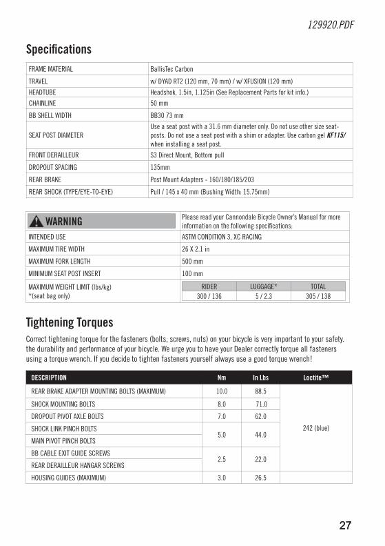
SpecificationsFRAME MATERIAL BallisTec Carbon
TRAVEL w/ DYAD RT2 (120 mm, 70 mm) / w/ XFUSION (120 mm)
HEADTUBE Headshok, 1.5in, 1.125in (See Replacement Parts for kit info.)
CHAINLINE 50 mm
BB SHELL WIDTH BB30 73 mm
SEAT POST DIAMETERUse a seat post with a 31.6 mm diameter only. Do not use other size seat-posts. Do not use a seat post with a shim or adapter. Use carbon gel KF115/ when installing a seat post.
FRONT DERAILLEUR S3 Direct Mount, Bottom pull
DROPOUT SPACING 135mm
REAR BRAKE Post Mount Adapters - 160/180/185/203
REAR SHOCK (TYPE/EYE-TO-EYE) Pull / 145 x 40 mm (Bushing Width: 15.75mm)
waRnInG Please read your Cannondale Bicycle Owner’s Manual for more information on the following specifications:
INTENDED USE ASTM CONDITION 3, XC RACING
MAXIMUM TIRE WIDTH 26 X 2.1 in
MAXIMUM FORK LENGTH 500 mm
MINIMUM SEAT POST INSERT 100 mm
MAXIMUM WEIGHT LIMIT (lbs/kg) *(seat bag only)
RIDER LUGGAGE* TOTAL 300 / 136 5 / 2.3 305 / 138
Tightening TorquesCorrect tightening torque for the fasteners (bolts, screws, nuts) on your bicycle is very important to your safety.the durability and performance of your bicycle. We urge you to have your Dealer correctly torque all fasteners using a torque wrench. If you decide to tighten fasteners yourself always use a good torque wrench!
DESCRIPTIOn nm In lbs loctite™
REAR BRAKE ADAPTER MOUNTING BOLTS (MAXIMUM) 10.0 88.5
242 (blue)
SHOCK MOUNTING BOLTS 8.0 71.0
DROPOUT PIVOT AXLE BOLTS 7.0 62.0
SHOCK LINK PINCH BOLTS5.0 44.0
MAIN PIVOT PINCH BOLTS
BB CABLE EXIT GUIDE SCREWS2.5 22.0
REAR DERAILLEUR HANGAR SCREWS
HOUSING GUIDES (MAXIMUM) 3.0 26.5
2828
4
7
3
4
10
9
28
15
M4X8M4X16
M4X13
M4X13
6
5mmLoctite 242 (blue)7 Nm (62 InLbs)
5mmLoctite 242 (blue)10 Nm (88.5 InLbs)
5mmLoctite 242 (blue)7 Nm (62 InLbs)
Loctite 242 (blue)2.5 Nm (22 InLbs)
1211
DROPOuT - TRIGGER 29’ER
IDEnTIFICaTIOn1. Seat Stay2. Left Dropout3. Right Dropout4. Pivot Spacers5. Pivot Axle Bolts6. 135mm Hub Spacers7. Rear Derailleur Hanger8. 12mm Rear Axle9. Brake Adapter(s)
10. Chainring Bolts 16mm11. Circlip12. Bearing
Before attachment, inspect the bearings to make sure they are in good condition.
Check the seat stay If the bearings are damaged, remove them and replace them with new ones.
Always insert small end of pivot spacers into the bearings. The flat side of the spacers face out.
Always insert a 5mm hex key completely into the axle bolts to prevent damage when turning the bolt.
Always tighten with a torque wrench to the specified torque.
29
129920.PDF
5mmLoctite 242 (blue)7 Nm (62 InLbs)
1
c
d2
3
a
b
6
5
5 M8X30
M5X16
85mmLoctite 242 (blue)5 Nm (44 InLbs)
5
5mmLoctite 242 (blue)8 Nm (71 InLbs)
7
4
KP169/
1211
9
c
3 b
b
d
c
3 b
b
d
29
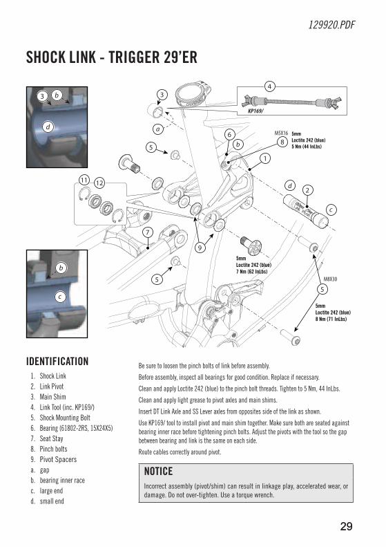
SHOCK lInK - TRIGGER 29’ER
IDEnTIFICaTIOn1. Shock Link2. Link Pivot3. Main Shim4. Link Tool (inc. KP169/)5. Shock Mounting Bolt6. Bearing (61802-2RS, 15X24X5)7. Seat Stay8. Pinch bolts9. Pivot Spacersa. gapb. bearing inner racec. large endd. small end
nOTICEIncorrect assembly (pivot/shim) can result in linkage play, accelerated wear, or damage. Do not over-tighten. Use a torque wrench.
Be sure to loosen the pinch bolts of link before assembly.
Before assembly, inspect all bearings for good condition. Replace if necessary.
Clean and apply Loctite 242 (blue) to the pinch bolt threads. Tighten to 5 Nm, 44 InLbs.
Clean and apply light grease to pivot axles and main shims.
Insert DT Link Axle and SS Lever axles from opposites side of the link as shown.
Use KP169/ tool to install pivot and main shim together. Make sure both are seated against bearing inner race before tightening pinch bolts. Adjust the pivots with the tool so the gap between bearing and link is the same on each side.
Route cables correctly around pivot.
30
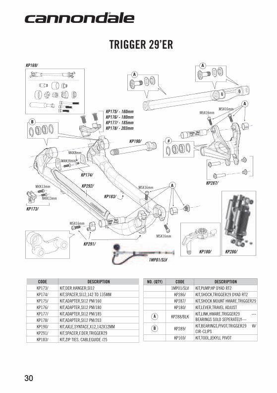
CODE DESCRIPTIOnKP173/ KIT,DER.HANGER;SI12KP174/ KIT,SPACER,SI12,142 TO 135MMKP175/ KIT,ADAPTER,SI12 PM/160KP176/ KIT,ADAPTER,SI12 PM/180KP177/ KIT,ADAPTER,SI12 PM/185KP178/ KIT,ADAPTER,SI12 PM/203KP190/ KIT,AXLE,SYNTACE,X12,142X12MMKP291/ KIT,SPACER,F.DER,TRIGGER29KP183/ KIT,ZIP TIES, CABLEGUIDE /25
nO. (QTY) CODE DESCRIPTIOn1MP01/SLV KIT,PUMP,HP DYAD RT2
KP286/ KIT,SHOCK,TRIGGER29 DYAD RT2KP287/ KIT,SHOCK MOUNT HWARE,TRIGGER29KP180/ KIT,LEVER,TRAVEL ADJUST
KP288/BLKKIT,LINK,HWARE,TRIGGER29 --- BEARINGS SOLD SEPERATELY---
KP289/KIT,BEARINGS,PIVOT,TRIGGER29 W/CIR-CLIPS
KP169/ KIT,TOOL,JEKYLL PIVOT
KP287/
M5X16mmM5X16mm
A
M5X16mm
KP173/
KP174/
KP190/
KP292/
M5X16mm
M5X16mm
KP291/
AM4X13mm
M4X13mm
M4X16mm
M4X8mm
KP175/ - 160mmKP176/ - 180mmKP177/ - 185mmKP178/ - 203mm
B
KP169/
A
A
B
KP286/
1MP01/SLV
KP180/
KP183/
TRIGGER 29’ER
30
31
129920.PDF
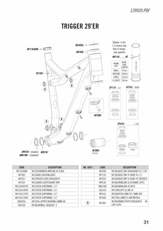
CODE DESCRIPTIOnKP170/GRN KIT,SEATBINDER,MTN QR,34.9,BLK
KP290/ KIT,GUIDE,HOUSING,BOLTKP291/ KIT,SPACER,F.DER,TRIGGER29KF103/ KIT,GUARD,SCUFFGUARD-8PK
KH118/097HT KIT,STEER,SUPERMAX, 1.5”KH118/109HT KIT,STEER,SUPERMAX, 1.5”KH118/122HT KIT,STEER,SUPERMAX, 1.5”KH118/134HT KIT,STEER,SUPERMAX, 1.5”
QSISEAL/ KIT,SEAL,UPPER BEARING,58MM ODHD169/ KIT,BEARINGS, HEADSET- 2
nO. (QTY) CODE DESCRIPTIOnKP058/ KIT,HEADSET,INT HEADSHOK TO 1 1/8”KP119/ KIT,HEADSET,INT H-SHOK TO 1.5KP205/ KIT,HEADSET,INT H-SHOK TO TAPEREDKP018/ KIT,BEARING,BB-SI,CERAMIC,2PCS
KB6180/ KIT,BEARING,BB-SI,2PCSQC616/ KIT,CIRCLIPS (2) BB-SI KP010/ KIT,ADAPTER,SIBB TO 73MM TAPKF368/ KIT,TOOL,SIBB/73 ADP.INSTALL
KP289/KIT,BEARINGS,PIVOT,TRIGGER29 W/CIR-CLIPS
TRIGGER 29’ER
KH118/ _ _ _HT
Steerer is for 1.5 stems onlyAnd is frame size specific
FRAME SIZE
HEAD-TUBE
LENGTH SMALL 97mm
MEDIUM 109mmLARGE 122mm
X-LARGE 134mm
KF368/73 mmQC616/KP018/ - ceramic
KB6180/ - standard
QSISEAL
HD169/
KF103/
KP290/
KP170/GRN
12 mm
KP058/ 1 1/8”
KP119/ 1.5” KP205/ TAPER
31
3232
M
H N
F
BP
I
D
E’
K L J
AO
C
E
ASTM F2043
For extremeo�-road riding
ASTM CONDITION 4ALL-MOUNTAIN
G
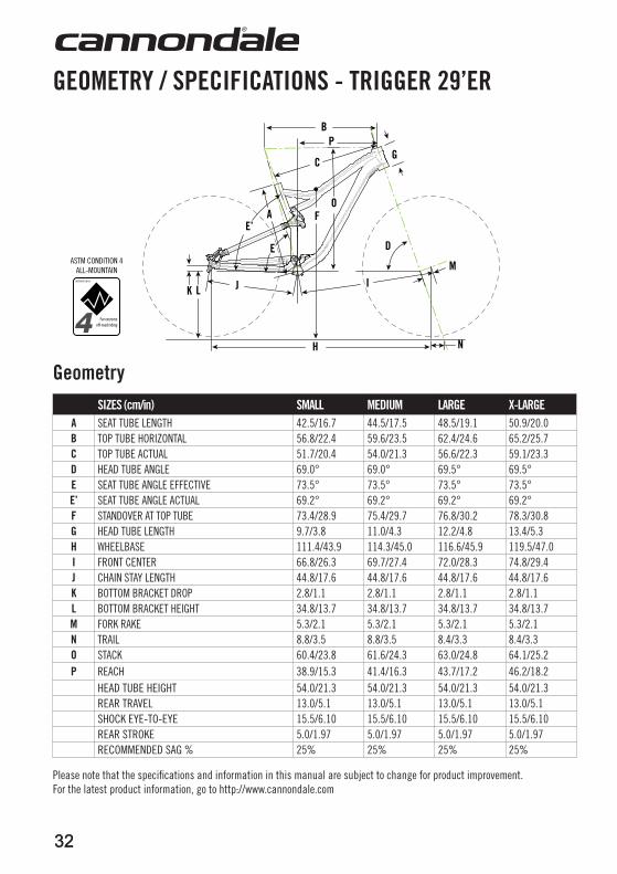
GeometrySIZES (cm/in) SMall MEDIuM laRGE X-laRGE
a SEAT TUBE LENGTH 42.5/16.7 44.5/17.5 48.5/19.1 50.9/20.0B TOP TUBE HORIZONTAL 56.8/22.4 59.6/23.5 62.4/24.6 65.2/25.7C TOP TUBE ACTUAL 51.7/20.4 54.0/21.3 56.6/22.3 59.1/23.3D HEAD TUBE ANGLE 69.0° 69.0° 69.5° 69.5°E SEAT TUBE ANGLE EFFECTIVE 73.5° 73.5° 73.5° 73.5°E’ SEAT TUBE ANGLE ACTUAL 69.2° 69.2° 69.2° 69.2°F STANDOVER AT TOP TUBE 73.4/28.9 75.4/29.7 76.8/30.2 78.3/30.8G HEAD TUBE LENGTH 9.7/3.8 11.0/4.3 12.2/4.8 13.4/5.3H WHEELBASE 111.4/43.9 114.3/45.0 116.6/45.9 119.5/47.0I FRONT CENTER 66.8/26.3 69.7/27.4 72.0/28.3 74.8/29.4J CHAIN STAY LENGTH 44.8/17.6 44.8/17.6 44.8/17.6 44.8/17.6K BOTTOM BRACKET DROP 2.8/1.1 2.8/1.1 2.8/1.1 2.8/1.1l BOTTOM BRACKET HEIGHT 34.8/13.7 34.8/13.7 34.8/13.7 34.8/13.7M FORK RAKE 5.3/2.1 5.3/2.1 5.3/2.1 5.3/2.1n TRAIL 8.8/3.5 8.8/3.5 8.4/3.3 8.4/3.3O STACK 60.4/23.8 61.6/24.3 63.0/24.8 64.1/25.2P REACH 38.9/15.3 41.4/16.3 43.7/17.2 46.2/18.2
HEAD TUBE HEIGHT 54.0/21.3 54.0/21.3 54.0/21.3 54.0/21.3REAR TRAVEL 13.0/5.1 13.0/5.1 13.0/5.1 13.0/5.1SHOCK EYE-TO-EYE 15.5/6.10 15.5/6.10 15.5/6.10 15.5/6.10REAR STROKE 5.0/1.97 5.0/1.97 5.0/1.97 5.0/1.97RECOMMENDED SAG % 25% 25% 25% 25%
GEOMETRY / SPECIFICaTIOnS - TRIGGER 29’ER
Please note that the specifications and information in this manual are subject to change for product improvement. For the latest product information, go to http://www.cannondale.com
33
129920.PDF
33
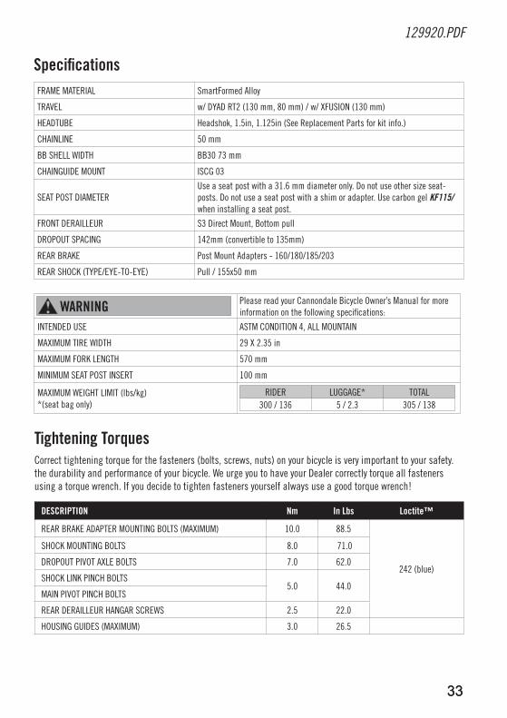
SpecificationsFRAME MATERIAL SmartFormed Alloy
TRAVEL w/ DYAD RT2 (130 mm, 80 mm) / w/ XFUSION (130 mm)
HEADTUBE Headshok, 1.5in, 1.125in (See Replacement Parts for kit info.)
CHAINLINE 50 mm
BB SHELL WIDTH BB30 73 mm
CHAINGUIDE MOUNT ISCG 03
SEAT POST DIAMETERUse a seat post with a 31.6 mm diameter only. Do not use other size seat-posts. Do not use a seat post with a shim or adapter. Use carbon gel KF115/ when installing a seat post.
FRONT DERAILLEUR S3 Direct Mount, Bottom pull
DROPOUT SPACING 142mm (convertible to 135mm)
REAR BRAKE Post Mount Adapters - 160/180/185/203
REAR SHOCK (TYPE/EYE-TO-EYE) Pull / 155x50 mm
waRnInG Please read your Cannondale Bicycle Owner’s Manual for more information on the following specifications:
INTENDED USE ASTM CONDITION 4, ALL MOUNTAIN
MAXIMUM TIRE WIDTH 29 X 2.35 in
MAXIMUM FORK LENGTH 570 mm
MINIMUM SEAT POST INSERT 100 mm
MAXIMUM WEIGHT LIMIT (lbs/kg) *(seat bag only)
RIDER LUGGAGE* TOTAL 300 / 136 5 / 2.3 305 / 138
Tightening TorquesCorrect tightening torque for the fasteners (bolts, screws, nuts) on your bicycle is very important to your safety.the durability and performance of your bicycle. We urge you to have your Dealer correctly torque all fasteners using a torque wrench. If you decide to tighten fasteners yourself always use a good torque wrench!
DESCRIPTIOn nm In lbs loctite™
REAR BRAKE ADAPTER MOUNTING BOLTS (MAXIMUM) 10.0 88.5
242 (blue)
SHOCK MOUNTING BOLTS 8.0 71.0
DROPOUT PIVOT AXLE BOLTS 7.0 62.0
SHOCK LINK PINCH BOLTS5.0 44.0
MAIN PIVOT PINCH BOLTS
REAR DERAILLEUR HANGAR SCREWS 2.5 22.0
HOUSING GUIDES (MAXIMUM) 3.0 26.5
34
4
2
5
3
1
3
3
1
5
1 45 2
4
5
3
1
3
3
1
5
1 4
4
2
5
3
1
3
3
1
5
1 45 2
34
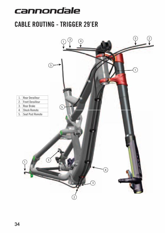
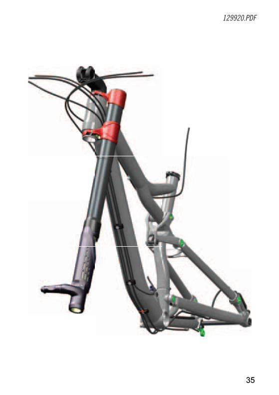
CaBlE ROuTInG - TRIGGER 29’ER
1. Rear Derailleur2. Front Derailleur3. Rear Brake 4. Shock Remote5. Seat Post Remote
35
129920.PDF
35
3636
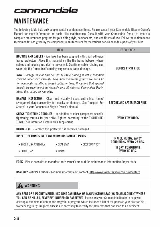
MaInTEnanCEThe following table lists only supplemental maintenance items. Please consult your Cannondale Bicycle Owner’s Manual for more information on basic bike maintenance. Consult with your Cannondale Dealer to create a complete maintenance program for your riding style, components, and conditions of use. Follow the maintenance recommendations given by the component manufacturers for the various non-Cannondale parts of your bike.
ITEM FREQUENCY
HOuSInG anD CaBlES - Your bike has been supplied with small adhesive frame protectors. Place this material on the the frame between where cables and housing rub due to movement. Overtime, cable rubbing can wear into the frame itself causing very serious frame damage.
NOTE: Damage to your bike caused by cable rubbing is not a condition covered under your warranty. Also, adhesive frame guards are not a fix for incorrectly installed or routed cables or lines. If you find that applied guards are wearing out very quickly, consult with your Cannondale Dealer about the routing on your bike.
BEFORE FIRST RIDE
DaMaGE InSPECTIOn - Clean and visually inspect entire bike frame/swingarm/linkage assembly for cracks or damage. See “Inspect For Safety” in your Cannondale Bicycle Owner’s Manual.
BEFORE anD aFTER EaCH RIDE
CHECK TIGHTEnInG TORQuES - In addition to other component specific tightening torques for your bike. Tighten according to the TIGHTENING TORQUES information listed in this supplement.
EVERY FEw RIDES
CHaIn PlaTE - Replace this protector if it becomes damaged.
InSPECT BEaRInGS, REPlaCE wORn OR DaMaGED PaRTS :
• SHOCK LINK ASSEMBLY • SEAT STAY • DROPOUT PIVOT
• CHAIN STAY • FRAME
In wET, MuDDY, SanDY COnDITIOnS EVERY 25 HRS.
In DRY, COnDITIOnS EVERY 50 HRS.
FORK - Please consult the manufacturer’s owner’s manual for maintenance information for your fork .
DYaD RT2 Rear Pull Shock - For more informatiomn contact: http://www.foxracingshox.com/fox/contact
waRnInG
anY PaRT OF a POORlY MaInTaInED BIKE Can BREaK OR MalFunCTIOn lEaDInG TO an aCCIDEnT wHERE YOu Can BE KIllED, SEVERElY InJuRED OR PaRalYZED. Please ask your Cannondale Dealer to help you develop a complete maintenance program, a program which includes a list of the parts on your bike for YOU to check regularly. Frequent checks are necessary to identify the problems that can lead to an accident.
CANNONDALE USACycling Sports Group, Inc.172 Friendship Road, Bedford, Pennsylvania, 15522-6600, USA(Voice): 1-800-BIKE-USA (Fax): [email protected]
CANNONDALE EUROPECycling Sports Group Europe, B.V.mail: Postbus 5100visits: Hanzepoort 277570 GC, Oldenzaal, Netherlands(Voice): +41 61.4879380 (Fax): [email protected]
WARNING! READ THIS SUPPLEMENT AND YOUR CANNONDALE BICYCLE OWNER’S MANUAL. BOTH CONTAIN IMPORTANT SAFETY INFORMATION. KEEP BOTH FOR FUTURE REFERENCE.
CANNONDALE UKCycling Sports GroupVantage Way, The Fulcrum, Poole, Dorset, BH12 4NU(Voice): +44 (0)1202 732288(Fax): +44 (0)1202 [email protected]
CANNONDALE AUSTRALIACycling Sports GroupUnit 8, 31-41 Bridge RoadStanmore NSW 2048Phone: +61 (0)2 8595 4444Fax: +61 (0) 8595 [email protected]
CANNONDALE JAPANNamba Sumiso Building 9F, 4-19, Minami Horie 1-chome,Nishi-ku, Osaka 550-0015, Japan(Voice): 06-6110-9390(Fax): [email protected]
WWW.CANNONDALE.COM© 2012 Cycling Sports Group129920 (12/12)
TRIG
GER
29ER
& T
RIGG
ER 2
6ER
OW
NER’
S M
ANUA
L SU
PPLE
MEN
T
TRIGGER 29ER & TRIGGER 26ER.OWNER’S MANUAL SUPPLEMENT.
129920