1260Sc OWNER’S OPERATING MANUAL
20
1260Sc OWNER’S OPERATING MANUAL
Transcript of 1260Sc OWNER’S OPERATING MANUAL

1260Sc OWNER’S OPERATING MANUAL
Console tube
Front stabilizer
Handle Bar SeatMain Frame
Rear stabilizer
(B4) Screw M10 x 55
(B5) Washer M10
Tool
(K1)Pedal-L (A45) End Cap
(E4 / E5) End Cap
END CAP
(A44)SCREW M6X10
(M3)SCREW M4X16
(H1)SCREW M5X12
(K2)Pedal-R
Console
6m/m4m/m 5m/m3m/m2.5m/m#13 #14 #15 #17
L
H
D
B C
K
GE
M
A
Bottle holder
1
A
A
C
B4
B5
B
B4
B5
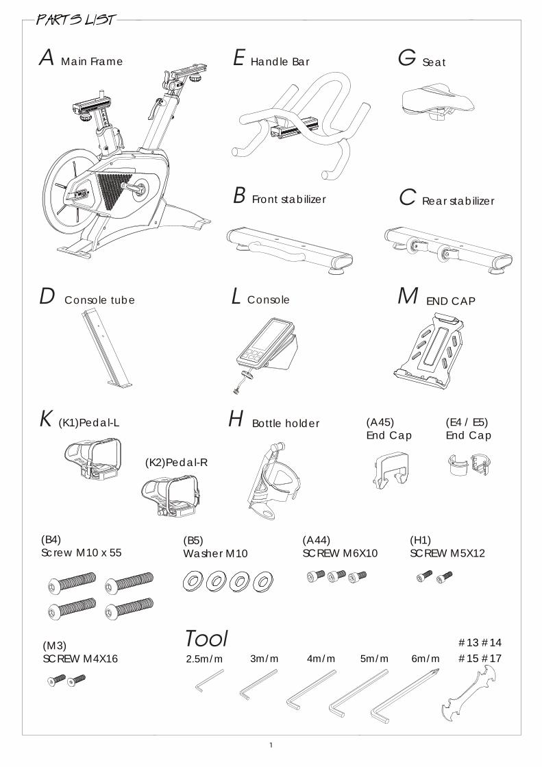
USE TOOL: #6 m/m
USE TOOL: #6 m/m
FIGURE 1 - HOW TO ASSEMBLE REAR STABILIZERAttach the rear stabilizer (C) onto main frame by using screw(B4) and washer (B5).
Attached the front stabilizer (B) onto main frame by using screw(B4) and washer (B5).
FIGURE 1
FIGURE 2HOW TO ASSEMBLE FRONT STABILIZERFIGURE 2 -
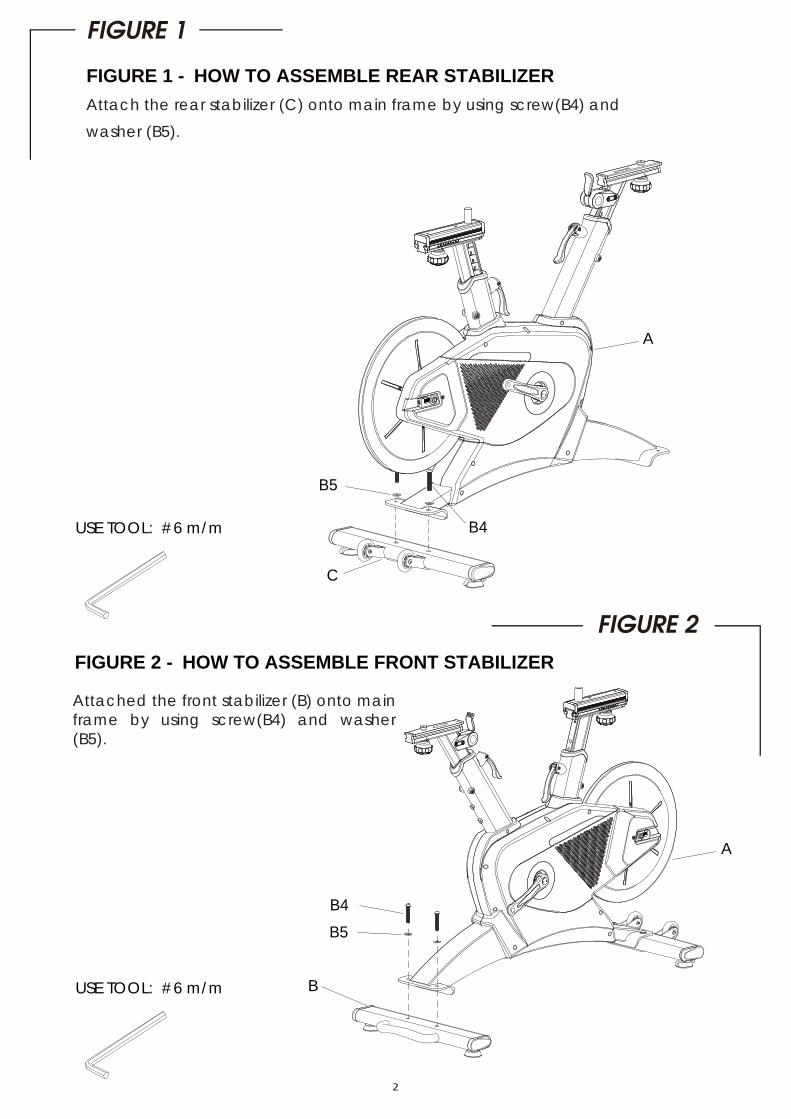
HOW TO ASSEMBLE THE HANDLE BAR
Step 1: View A shown: Loosen the adjusting knob and pull down the resistance lever.
Step 4: View D Shown: Slide the handle bar (E) to front and tight the screw (A44)at second hole position. After then,attach the plastic cover (A45).
Step 5: After the above steps completed, tight the adjusting knob (as View A shown) to finish the handle bar assembly.
Step 2: View B shown: Pull out the tied wires and locate it along the post. Sliding the handle bar tracking housing onto post and pull the tied wires together. Be careful not to pinching off the wires during the assembly.
Step 3: View C shown: Pull out the wire (E7) from the hole of handle bar(E) and combine the plastic cover (E4 & E5).
VIEW A
VIEW B
VIEW C
VIEW D
A45
A44
E4
E
E7E5
FIGURE 3
FIGURE 3 -

A44
D
LL7
E7
L
M
D
M3
H
A
H1
HOW TO ASSEMBLE CONSOLE
Step 1: Attach the console mast (D) at the first hole position and using screw (A44) to tight it.Step 2: Insert the console (L) into console mast(D) and connect the wires together. Remove the plastic end cap (E7) firstly and put the plastic end cap (L7) onto the hole and turn clockwise direction to tight it.
USE TOOL: #5 m/m
USE TOOL: #2.5 m/m
FIGURE 4FIGURE 4 -
FIGURE 5 -
Step 1:
Step 2. Use the two screws (H1) located in the water bottle holder bag to join the water bottle holder (H) to the main frame (A).
FIGURE 5
4
Put the tablet holder (M) onto the console mast (D) at vertical position and use 2PCS of screws (M3) fix it.
The console view angle can be adjusted as desired.
HOW TO ASSEMBLE THE TABLET HOLDER AND WATER BOTTLE HOLDER
Remark: When screw in the tablet holder, align the one hole with the console mast (D) to screw in firstly. Then, move the holder up to fix another hole.

USE TOOL: #13 #14 #15 #17
Put the saddle (G) onto sliding basement and using tool to tight it.
G
Fix the Right Pedal(screw clockwise) and left Pedal(screw counter-clockwise)to the crank.
USE TOOL: #13 #14 #15 #17
K1
K2
FIGURE 6
FIGURE 6 - HOW TO ASSEMBLE SADDLE
FIGURE 7FIGURE 7 - HOW TO ASSEMBLE PEDAL
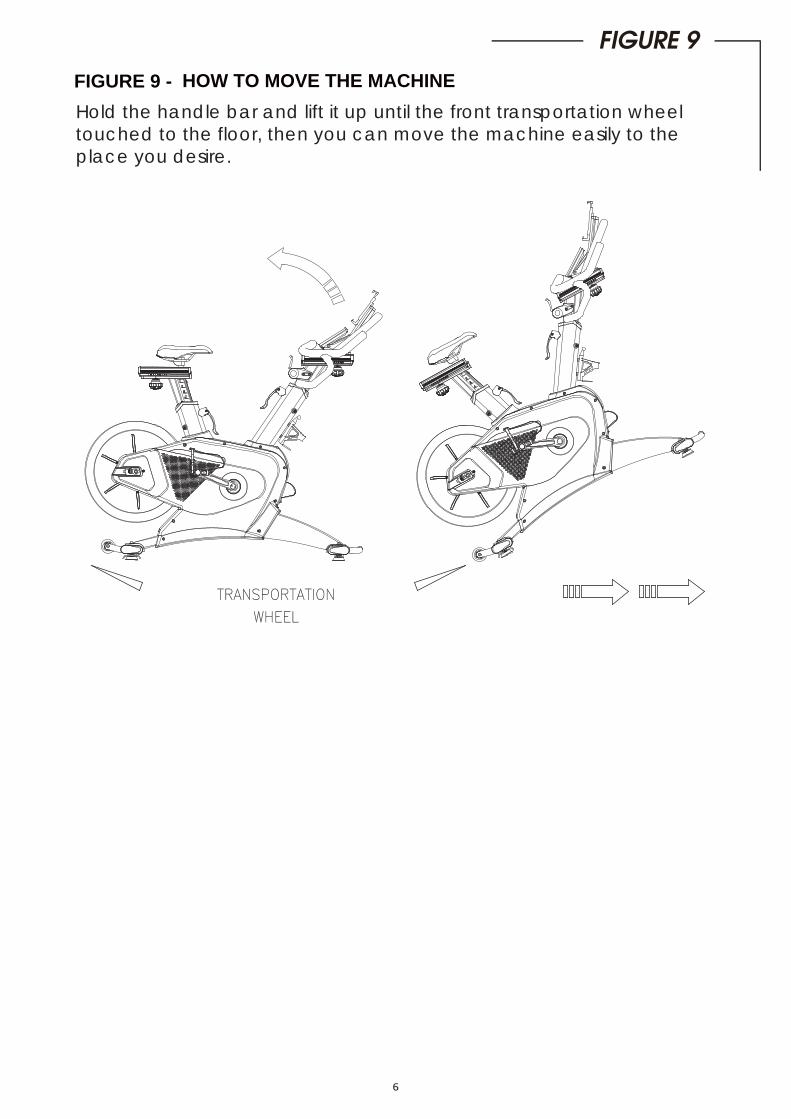
Hold the handle bar and lift it up until the front transportation wheel touched to the floor, then you can move the machine easily to theplace you desire.
HOW TO MOVE THE MACHINEFIGURE 9 -
FIGURE 9
6

View C: The lever is used for resistance adjustment. The lever is in upper position, the lighter resistance is. The lower position of lever, the heavier reistance is.
POSITION:1~9
POSITION:1~9VIEW A
VIEW C
VIEW B
POSITION:1~13POSITION:1~7
View A: Loosen the knob firslty and move to the proper position. After that, just tight the knob. It’s the same way for saddle and handle bar position adjustment.
HOW TO ADJUST THE HEIGHT OF SADDLE/HANDLE BAR AND RESISTANCE
View B: Lift up the grip and move it to the proper position. After then, just press the lever down tightly. It’s not necessary to find a hole after proper postion find, just press down the lever.
7
FIGURE 9 -
FIGURE 9
A70
A82
C9
A4
A23
C5
A71
A44
A1
A8
A3
A47
A5
A6
A35
A5
A6
A34
A39
A22
A14
B2
M1
A12
C4
A74
M2
A16
E2
A11
*5
A73
A13
L2
A72
A44
H
A59
D2
K2
E5
A61
E1
A90
E3*4
A37
B3
A43
A17
A44
M3
A20
A76
A83
D1
A66
L6
A78
A9*
3
A10
A45
A39
A81
*4
A14
A17
A38
A11
A11
B4
A63
L1
A40
A31
A15
A45
A34
A64
A80
A7
A77
A7
C3
B2
A68
A2
A40
A65
*3
C6
A24
A38
E7
A27
*2A
28
A89
A14
A79
A87
A35 A
21
A41
A45
A88
A48
A75
A62
A18
A39 A52
A41
C4
A19
A69
B5
C9
M4
A54
A84
A32
B1A
60
A8
A49
C5
A58
A67
G
B4A85
A30
A33
A25
*
A4
L4
A43
A16
C2
C2
C1
A9*
3
A44
A42
A46
A39
B5
K1
A26
*4
A29
L7L3
A45
C3
L5
E4
A10
A86
H1
A11
A11
A51
A35
A55
A50
A56
A36
A53
A57
Z V
IEW
Z V
IEW
A91
8

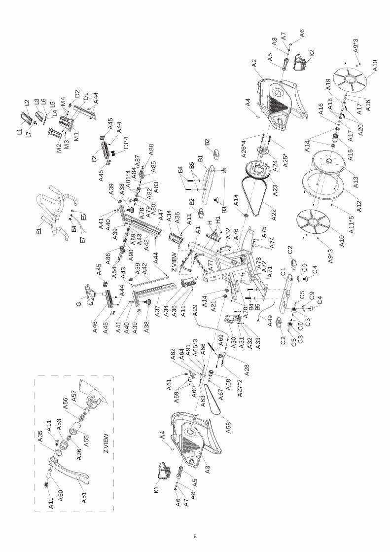
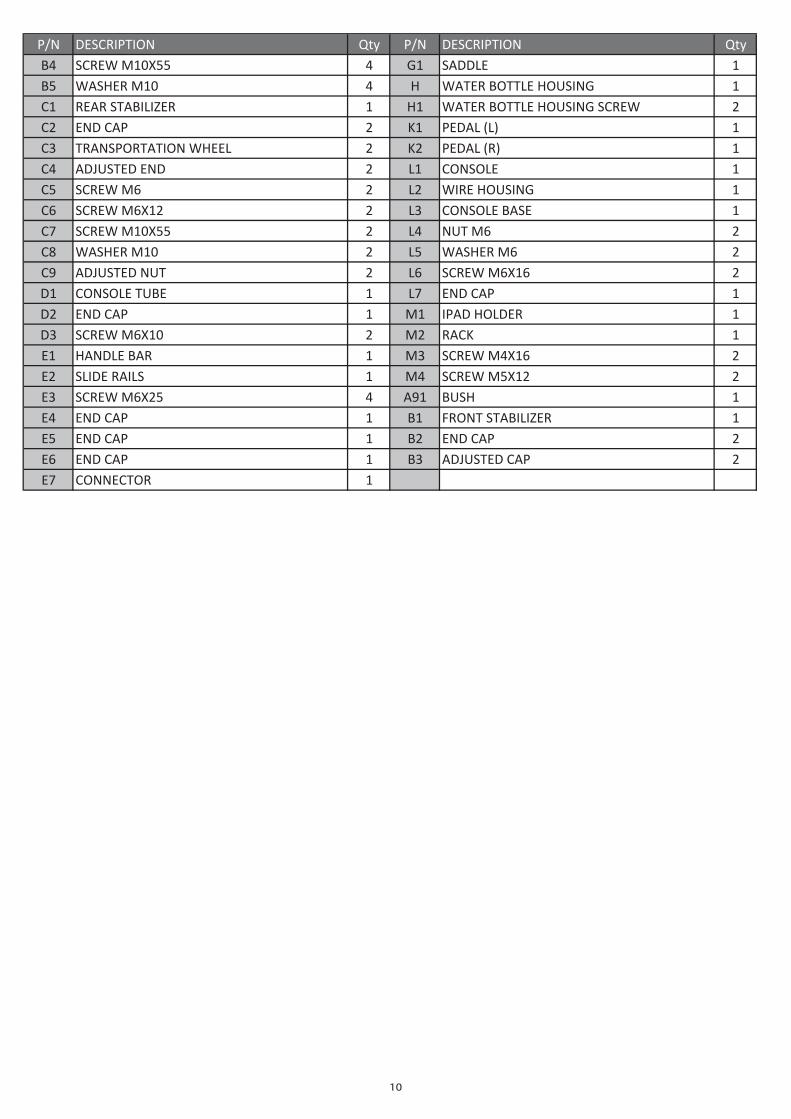
P/N DESCRIPTION Qty P/N DESCRIPTION QtyA1 MAIN FRAME 1 A46 SLIDE RAILS 1A2 CHAIN COVER (R) 1 A47 CONSOLE TUBE 1A3 CHAIN COVER (L) 1 A48 ADJUSTING BOARD 1A4 FOAM DOUBLE SIDED ADHESIVE 2 A49 DJ JACK 1A5 CRANK 2 A50 BUSH 2A6 CRANK CAP 2 A51 HANDLE 2A7 NUT 2 A52 GENERATOR CONTROL PLATE 1A8 WASHER 2 A53 SPRING 2A9 SCREW M4X16 6 A54 SCREW M5X40 2
A10 TURING PLATE COVER 2 A55 BRAKE PAD 2A11 SCREW M5X10 13 A56 SPRING 2A12 ALUMINUM RING 1 A57 AXLE 2A13 FLYWHEEL 1 A58 BELT 2PJ 1016 1A14 BEARING (6004) 4 A59 SCREW M5X12 2A15 SMALL BELT WHEEL 1 A60 WASHER M5 2A16 NUT M10 2 A61 SPRING 1A17 WASHER M10 2 A62 GENERATOR FIXED PLATE 1A18 NUT M17 2 A63 SCREW M6X60 1A19 AXLE 1 A64 GENERATOR SHAFT 1A20 SCREW M6X50 2 A65 WASHER M6 3A21 NUT M20X12T 1 A66 NUT M6 1A22 BELT 5PK 1387 1 A67 SCREW M6X12 1A23 DRIVING WHEEL 1 A68 GENERATOR 1A24 AXLE 1 A69 SPRING 1A25 SPRING WASHER M8 4 A70 SCREW M5X12 2A26 SCREW M8X15 4 A71 SENSOR WIRE 1A27 SCREW M8X60 2 A72 SENSOR WIRE HOUSING 1A28 TENSION ASJUSTER 1 A73 SENSOR WIRE HOUSING SCREW 1A29 TENSION CABLE 1 A74 WASHER 2A30 MAGNETIC HOUSING 1 A75 NUT M8 2A31 SCREW M6X15 2 A76 BATTERY 1A32 WASHER M6 4 A77 SCREW M6X16 1A33 NUT M6 2 A78 PULLEY 1A34 PLASTIC PIPE 2 A79 HANDLE 1A35 BUSHING PAD 6 A80 FIXING PAD 2A36 SCREW M5X8 1 A81 SCREW M3X8 8A37 SADDLE SUPPORT TUBE 1 A82 SECTOR PAD 2A38 KNOB 2 A83 WASHER M6 2A39 END CAP 4 A84 SCREW M6X40 1A40 SCREW SLEEVE 2 A85 LEVER COVER (R) 1A41 SCREW M4X10 2 A86 LEVER COVER (L) 1A42 ADJUSTING BOARD 1 A87 NUT M5 2A43 SCREW M3X6 2 A88 SMALL CAP 2A44 SCREW M6X10 5 A89 TENSION WHEEL 1A45 END CAP 4 A90 NUT M6 1
10
ytQNOITPIRCSEDN/PytQNOITPIRCSEDN/PB4 SCREW 1ELDDAS1G455X01MB5 WASHER RETAWH401M BOTTLE HOUSING 1C1 REAR RETAW1H1REZILIBATS BOTTLE HOUSING SCREW 2C2 END LADEP1K2PAC 1)L(C3 TRANSPORTATION WHEEL 2 K2 PEDAL 1)R(C4 ADJUSTED 1ELOSNOC1L2DNEC5 SCREW ERIW2L26M 1GNISUOHC6 SCREW ELOSNOC3L221X6M 1ESABC7 SCREW TUN4L255X01M 26MC8 WASHER REHSAW5L201M 26MC9 ADJUSTED WERCS6L2TUN 261X6MD1 CONSOLE DNE7L1EBUT 1PACD2 END DAPI1M1PAC 1REDLOHD3 SCREW 1KCAR2M201X6ME1 HANDLE WERCS3M1RAB 261X4ME2 SLIDE WERCS4M1SLIAR 221X5ME3 SCREW 1HSUB19A452X6ME4 END TNORF1B1PAC 1REZILIBATSE5 END DNE2B1PAC 2PACE6 END DETSUJDA3B1PAC 2PAC
1ROTCENNOC7E
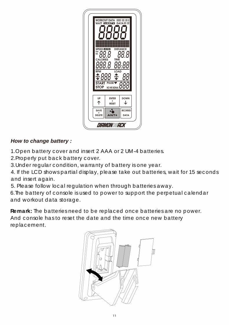
How to change battery :
1. Open battery cover and insert 2 AAA or 2 UM-4 batteries.2. Properly put back battery cover.3. Under regular condition, warranty of battery is one year.4. If the LCD shows partial display, please take out batteries, wait for 15 and insert again.
seconds
5. Please follow local regulation when through batteries away.
11
6.The battery of console is used to power to support the perpetual calendar and workout data storage.
Remark: The batteries need to be replaced once batteries are no power. And console has to reset the date and the time once new battery replacement.

Functions A.Console functions
1. Scope of application: SPIN BIKE 2. Operating voltage: 3V 3. Main functions: TIME, SPEED, DIST, CAL, RPM, PULSE, LOAD, WATT,
PERSONALIZED WORKOUT DATA STORAGE, PERPETUAL CALENDAR, TARGET TIME, TARGET DIST, TARGET CAL, TARGET WATT
D. Paired with Battery Mode / Self-generated Electricity Mode / Adopter Mode B.Button functions
1 ENTER/RESET KEY 1 Select TIME / DIST / CAL function 2 Confirmed the function 3 Press and hold the key for reboot
2 UP KEY Press UP KEY to adjust values during setting Press UP KEY to adjust LEVEL after START
3 DOWN KEY Press DOWN KEY to adjust values during setting Press DOWN KEY to adjust LEVEL after START
4 RESET KEY Press RESET KEY under STAND BY mode to reboot the system
5 RECORDED DATA KEY: When search for data, press RECORDED DATA key when the console is paused When there is no data, the screen will show NO DATA, when there is data then it will
show the numbers of stored data 6 SAVE DELETE KEY: When work out was paused and the LCD displayed shows STOP, press SAVE.DELETE
key and the data display area will show whether the data is saved. Press ENTER to save the data.
Under RECORDED DATA mode, press SAVE.DELETE to delete the stored data that you selected.
Under RECORDED DATA mode, press and hold the key for 5 seconds to delete all stored data.
7 ANT+ ON/OFF KEY: Press ANT+ ON/OFF once to activate ANT module function. And to turn off the function.
Power on/off : A. Power on
1. After powering on, the LCD will be in full display for one second and a long sound will be heard (when the Beeping
beeping function is on), enter TIME setting mode.
2. If there’s no signal input in 4 seconds, the time will pause, the console will BY mode.
enter STAND
B. Power off: 1. If there’s no signal input in 4 minutes, the IC will enter SLEEP mode. 2. When there is signal input or button input, the console will WAKE UP.
12
12

image 1 image 2 image 3 image 4 image 5
YEAR SELECT PRESS ENTER MONTH SELECT PRESS ENTER DAY SELECT
PRESS ENTER HOUR SELECT PRESS ENTER PRESS ENTERMINUTE SELECT
NOTE: the date and time should be set up again while batteries replaced.
Operating Instructions After the power is on, the LCD enters the time setting mode after 1 second. (After this setting, the setting mode will no longer be displayed the next time the power is turned on, unless the batteries are removed or replaced.)
YEAR: Range from 2018 to 2099. Default value: 2018 (image1) MONTH: Range from 1 to 12. Default value: 1 (image2) DAY: Range from 1 to 31. Default value: 1 (image3) HOUR: Range from 0 to 23. Default value: 0 (image4) MINUTE: Range from 0 to59. Default value: 0 (image5)
A.Time setting mode:
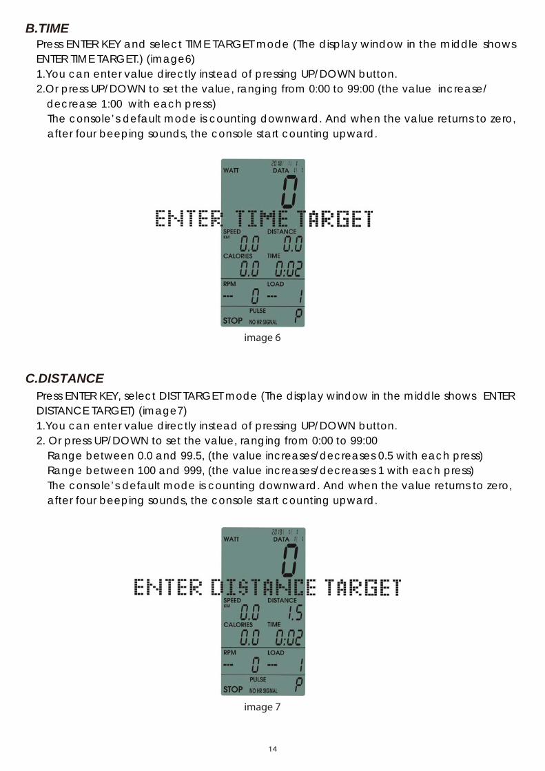
Press ENTER KEY and select TIME TARGET mode (The display window in the middle ENTER TIME TARGET
shows.) (image6)
1.You can enter value directly instead of pressing UP/DOWN button. 2.Or press UP/DOWN to set the value, ranging from 0:00 to 99:00 (the value
decrease 1:00increase/
with each press)The console’s default mode is counting downward. And when the value returns to zero, after four beeping sounds, the console start counting upward.
image 6
image 7
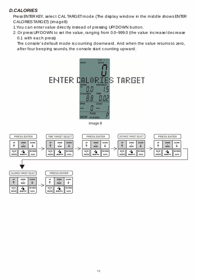
Press ENTER KEY, select DIST TARGET mode (The display window in the middle shows DISTANCE TARGET)
ENTER (image7)
1.You can enter value directly instead of pressing UP/DOWN button. 2. Or press UP/DOWN to set the value, ranging from 0:00 to 99:00
Range between 0.0 and 99.5, (the value increases/decreases 0.5 with each press)Range between 100 and 999, (the value increases/decreases 1 with each press)The console’s default mode is counting downward. And when the value returns to zero,after four beeping sounds, the console start counting upward.
B.TIME
C.DISTANCE
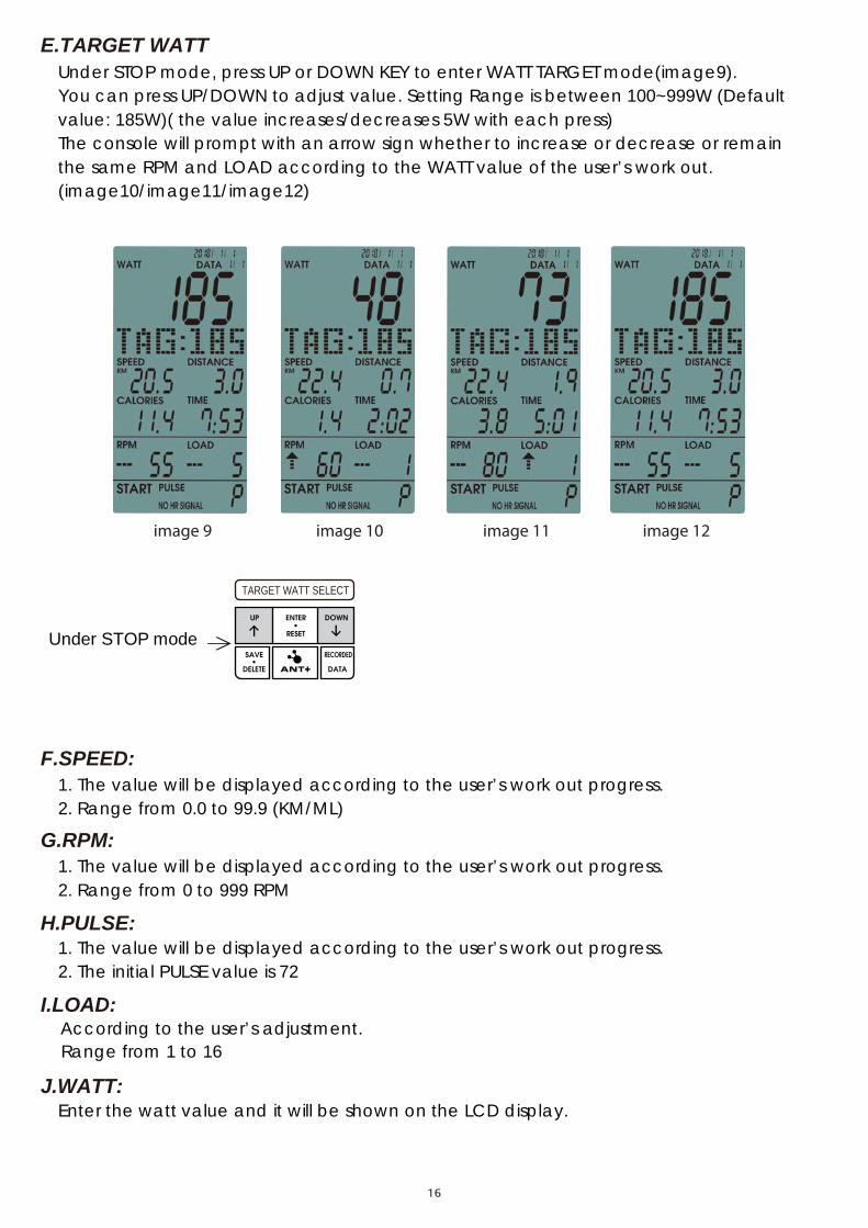
Press ENTER KEY, select CAL TARGET mode (The display window in the middle shows ENTER CALORIES TARGET) (image8) 1.You can enter value directly instead of pressing UP/DOWN button. 2. Or press UP/DOWN to set the value, ranging from 0.0~999.0 (the value
0.1 increase/decrease
with each press) The console’s default mode is counting downward. And when the value returns to zero, after four beeping sounds, the console start counting upward.
image 8
PRESS ENTER TIME TARGET SELECT PRESS ENTER DISTANCE TARGET SELECT PRESS ENTER
CALORIES TARGET SELECT PRESS ENTER
D.CALORIES
TARGET WATT SELECT
Under STOP mode,
Under STOP mode
press UP or DOWN KEY to enter WATT TARGET mode(image9). You can press UP/DOWN to adjust value. Setting Range is between 100~999W (Default value: 185W)( the value increases/decreases 5W with each press) The console will prompt with an arrow sign whether to increase or decrease or remain the same RPM and LOAD according to the WATT value of the user’s work out. (image10/image11/image12)
E.TARGET WATT
image 9 image 10 image 11 image 12
F.SPEED: 1. The value will be displayed according to the user’s work out progress. 2. Range from 0.0 to 99.9 (KM/ML)
G.RPM: 1. The value will be displayed according to the user’s work out progress.
2. Range from 0 to 999 RPM
H.PULSE: 1. The value will be displayed according to the user’s work out progress. 2. The initial PULSE value is 72
I.LOAD: According to the user’s adjustment.
Range from 1 to 16
J.WATT: Enter the watt value and it will be shown on the LCD display.
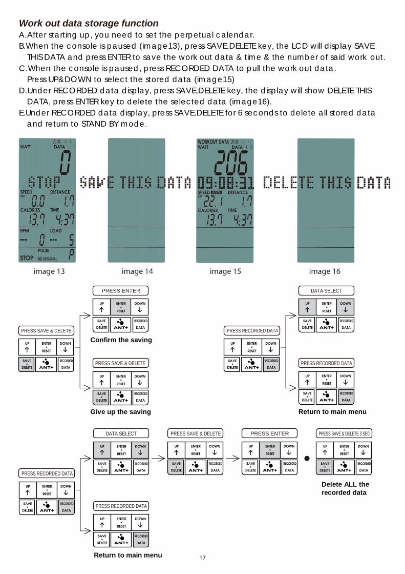
Work out data storage function A.After starting up, you need to set the perpetual calendar. B.When the console is paused (image13), press SAVE.DELETE key, the LCD will display SAVE
THIS DATA and press ENTER to save the work out data & time & the number of said work out. C.When the console is paused, press RECORDED DATA to pull the work out data.
Press UP&DOWN to select the stored data (image15) D.Under RECORDED data display, press SAVE.DELETE key, the display will show DELETE THIS
DATA, press ENTER key to delete the selected data (image16). E.Under RECORDED data display, press SAVE.DELETE for 6 seconds to delete all stored data
and return to STAND BY mode.
image 13 image 14 image 15 image 16
PRESS SAVE & DELETE
PRESS ENTER
PRESS SAVE & DELETE
Confirm the saving
Give up the saving
DATA SELECT
PRESS RECORDED DATA
PRESS RECORDED DATA
Return to main menu
PRESS ENTERDATA SELECT
PRESS RECORDED DATA
PRESS RECORDED DATA
PRESS SAVE & DELETE PRESS SAVE & DELETE 3 SEC
Delete ALL the recorded data
Return to main menu
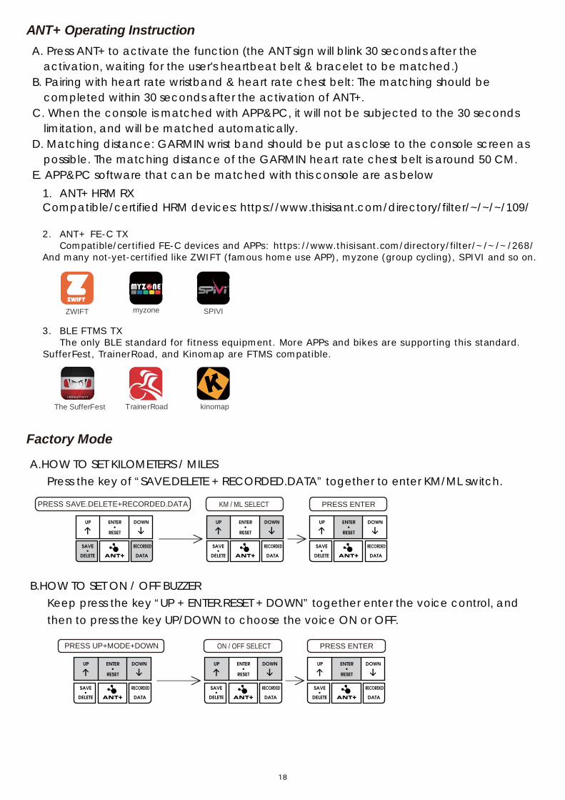
noitcurtsnI gnitarepO +TNAA. Press ANT+ to activate the function (the ANT sign will blink 30 seconds after the
activation, waiting for the user's heartbeat belt & bracelet to be matched.) B. Pairing with heart rate wristband & heart rate chest belt: The matching should be
completed within 30 seconds after the activation of ANT+. C. When the console is matched with APP&PC, it will not be subjected to the 30 seconds
limitation, and will be matched automatically. D. Matching distance: GARMIN wrist band should be put as close to the console screen as
possible. The matching distance of the GARMIN heart rate chest belt is around 50 CM. E. APP&PC software that can be matched with this console are as below
Factory Mode
1. ANT+ HRM RX Compatible/certified HRM devices: https://www.thisisant.com/directory/filter/~/~/~/109/ 2. ANT+ FE-C TX
Compatible/certified FE-C devices and APPs: https://www.thisisant.com/directory/filter/~/~/~/268/ And many not-yet-certified like ZWIFT (famous home use APP), myzone (group cycling), SPIVI and so on.
3. BLE FTMS TX
The only BLE standard for fitness equipment. More APPs and bikes are supporting this standard. SufferFest, TrainerRoad, and Kinomap are FTMS compatible.
TrainerRoad
ZWIFT SPIVImyzone
The SufferFest kinomap
KM / ML SELECT PRESS SAVE.DELETE+RECORDED.DATA PRESS ENTER
ON / OFF SELECT PRESS UP+MODE+DOWN PRESS ENTER
18
A.HOW TO SET KILOMETERS / MILES Press the key of “SAVE.DELETE + RECORDED.DATA” together to enter KM/ML switch.
B.HOW TO SET ON / OFF BUZZER Keep press the key “UP + ENTER.RESET + DOWN” together enter the voice control, and then to press the key UP/DOWN to choose the voice ON or OFF.

REMARK
A. The bike has to pedal over than 40RPM to power on the console screen. (Example: When pedaling under 40RPM, the console screen is blank.)
B.When stop pedaling, the display won’t be shut off until 120 seconds. After 120 sec., the console will enter Sleeping mode which means the display can’t be read.
C.If rechargeable lithium battery is under low power supply or damage, the console
display shown data will be disappeared once stop pedaling. D.There are two kinds power supply systems (Generator / DC adaptor) of the bike.
When adaptor is plug-in, the system will charge the adaptor power supply firstly.