INSTALLATION & OWNER’S MANUAL -...
16
97101807B INSTALLATION & OWNER’S MANUAL PROCONTROL II TM OPERATING SYSTEM PACKAGE 99101124, 99101125, 99101126 Sno-Way ®, Down Pressure ® and EIS ® are registered trademarks of Sno-Way International, Inc. ProControl ™ , MegaBlade ™ , V-Wing ™ , E-Z Switch ™ , Revolution ™ , MaxAdjust ™ , SpeedLock ™ , and QuickJack ™ are trademarks of Sno-Way International, Inc. ©2013 Sno-Way ® International
Transcript of INSTALLATION & OWNER’S MANUAL -...

97101807B
INSTALLATION & OWNER’S MANUAL
PROCONTROL IITM OPERATINGSYSTEM PACKAGE
99101124, 99101125, 99101126
Sno-Way®, Down Pressure® and EIS® are registered trademarks of Sno-Way International, Inc.ProControl™, MegaBlade™, V-Wing™, E-Z Switch™, Revolution™, MaxAdjust™, SpeedLock™, and QuickJack™
are trademarks of Sno-Way International, Inc.
©2013 Sno-Way® International

2
TABLE OF CONTENTSPage
INTRODUCTION ......................................................................................................... 3
SAFETY ...................................................................................................................... 4
INSTALLATION........................................................................................................... 5
Receiver Installation on Plow Power Pack ...................................................... 5
Receiver Installation on Salt Spreader ........................................................... 5
6 & 9 Cubic Foot Spreaders.............................................................................. 5
4 Cubic Foot Spreader....................................................................................... 6
Programming Receiver to Learn Transmitter Code(Wireless ProControl IlTM)........................................................................... 6
Control Harness Installation On Plow.............................................................. 7
Control Harness Installation On Salt Spreader............................................... 8
Power Harness.............................................................................................. 8
Control Harness........................................................................................... 9
OPERATION ............................................................................................................. 10
Theory of Operation ........................................................................................ 10
ProControl II™ Operation Basic Functions – All Plows............................... 10
Basic Functions: V-WingTM and RevolutionTM Plows.................................11
Basic Functions: Salt Spreaders 12
Extended Functions: All Plows 12
Programming a Macro................................................................................ 12
Common Macro Programming .................................................................. 13
Start/Stop Procedure for ProControl II™ Transmitters ........................... 13
Power Saving Mode.................................................................................... 13
Battery Charging ........................................................................................ 13
Diagnostic Functions ...................................................................................... 13
ProControl IITM Charging / Battery Maintenance and Replacement .......... 14
ProControl IITM Transmitter Mounting Instructions..................................... 14
Using the ProControl IITM to Aid in Mountingand Removing the Snow Plow.................................................................. 15
Storage (Hard-wired ProControl II™) ............................................................. 15
Wiring Schematics 15
ProControl II™ Battery Warranty.................................................................... 15
3
This manual was written for the assembly, installation andmaintenance of your new Sno-Way ProControl IITM
Operating System. Most importantly, this manual providesan operating plan for safe use. Refer to the Table ofContents for an outline of this manual.Please keep this manual with your machine at all times asreference material and so it can be passed on to the nextowner if the machine is sold.We require that you read and understand the contents ofthis manual COMPLETELY, especially the chapter onSAFETY, before attempting any procedure contained inthis manual.
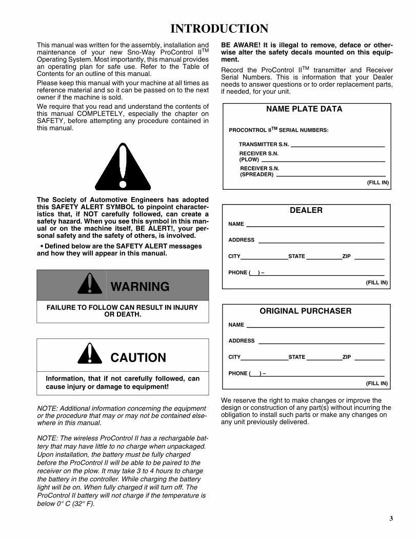
The Society of Automotive Engineers has adoptedthis SAFETY ALERT SYMBOL to pinpoint character-istics that, if NOT carefully followed, can create asafety hazard. When you see this symbol in this man-ual or on the machine itself, BE ALERT!, your per-sonal safety and the safety of others, is involved.
• Defined below are the SAFETY ALERT messages and how they will appear in this manual.
NOTE: Additional information concerning the equipment or the procedure that may or may not be contained else-where in this manual.
NOTE: The wireless ProControl II has a rechargable bat-tery that may have little to no charge when unpackaged. Upon installation, the battery must be fully charged before the ProControl II will be able to be paired to the receiver on the plow. It may take 3 to 4 hours to charge the battery in the controller. While charging the battery light will be on. When fully charged it will turn off. The ProControl II battery will not charge if the temperature is below 0° C (32° F).
BE AWARE! It is illegal to remove, deface or other-wise alter the safety decals mounted on this equip-ment.
Record the ProControl IITM transmitter and ReceiverSerial Numbers. This is information that your Dealerneeds to answer questions or to order replacement parts,if needed, for your unit.
We reserve the right to make changes or improve the design or construction of any part(s) without incurring the obligation to install such parts or make any changes on any unit previously delivered.
c WARNING
FAILURE TO FOLLOW CAN RESULT IN INJURY OR DEATH.
c CAUTION
Information, that if not carefully followed, cancause injury or damage to equipment!
DEALER
NAME
PHONE ( ) –
ADDRESS
CITY STATE ZIP
(FILL IN)
ORIGINAL PURCHASER
NAME
PHONE ( ) –
ADDRESS
CITY STATE ZIP
(FILL IN)
NAME PLATE DATA
(FILL IN)
PROCONTROL IITM SERIAL NUMBERS:
TRANSMITTER S.N.
RECEIVER S.N.
RECEIVER S.N.(SPREADER)
(PLOW)
INTRODUCTION
4
BEFORE ATTEMPTING ANY PROCEDURE IN THISBOOK, READ AND UNDERSTAND ALL THE SAFETYINFORMATION CONTAINED IN THIS SECTION. INADDITION, ENSURE ALL INDIVIDUALS WORKINGWITH YOU ARE ALSO FAMILIAR WITH THESESAFETY PRECAUTIONS.
For your safety Warning and Information Decals havebeen placed on this product to remind the operatorto take safety precautions. It is important that thesedecals are in place and are legible before operationbegins. New decals can be obtained from Sno-Way oryour local dealer.
REMEMBER The careful operator is the bestoperator. Most accidents are caused by human error.Certain precautions must be observed to prevent thepossibility of injury to operator or bystanders and/ordamage to equipment.
NEVER operate Plow when under the influence ofalcohol, drugs or other medications that could hamperyour judgement and reactions. An accident may result inserious injury or death to other persons or yourself.
ALWAYS operate vehicle in a well-ventilated area. Thecarbon monoxide in exhaust gas is highly toxic and cancause serious injury or death.
NEVER allow hands, hair or clothing to get near anymoving parts such as fan blades, belts and pulleys.Never wear neckties or loose clothing when working onthe vehicle.
NEVER wear wrist watches, rings or other jewelry whenworking on the vehicle or individual equipment. Thesethings can catch on moving parts or cause an electricalshort circuit that could result in serious personal injury.
ALWAYS wear safety goggles when working on thevehicle to protect your eyes from battery acid, gasoline,and dust or dirt from flying off of moving engine parts.
ALWAYS be aware of and avoid contact with hotsurfaces such as engine, radiator, and hoses.
ALWAYS wear safety glasses with side shields whenstriking metal against metal! In addition, it isrecommended that a softer (non-chipable) metal materialbe used to cushion the blow. Failure to heed could resultin serious injury to the eye(s) or other parts of the body.
NEVER allow children or unauthorized person tooperate this unit.
NEVER exceed 45 m.p.h. when snow plow is attachedto vehicle. Braking distances may be increased andhandling characteristics may be impaired at speedsabove 45 m.p.h.
ALWAYS lock the vehicle when unattended to preventunauthorized operation of the plow.
ALWAYS check the job site for terrain hazards,obstructions and people.
NEVER exceed 10 m.p.h. when plowing. Excessivespeed may cause serious injury and damage ofequipment and property if an unseen obstacle isencountered while plowing.
ALWAYS position blade so it does not block path ofheadlamps beam. Do not change blade positions whiletraveling. An incorrect plow position blocking headlampbeam may result in an accident.
ALWAYS check surrounding area for hazardousobstacles before operating this unit.
ALWAYS inspect the unit periodically for defects. Partsthat are broken, missing or plainly worn must be replacedimmediately. The unit, or any part of it should not bealtered without prior written approval of the manufacturer.
ALWAYS insert the cylinder lock when plow is not inuse. If the cylinder lock is not installed, the plow bladecould inadvertently drop and cause serious injury.
ALWAYS shut off the vehicle engine, place thetransmission in Neutral or Park, turn the ignition switch tothe “OFF” position and firmly apply the parking brake ofthe vehicle before attaching or detaching the blade fromthe vehicle or when making adjustments to the blade.
ALWAYS inspect lift system bolts and pins wheneverattaching or detaching the plow, and before traveling.Worn or damaged components could result in the plowdropping to the pavement while driving, causing anaccident.
ALWAYS keep hands and feet clear of blade and A-Frame when attaching or detaching plow.
NEVER stand between the vehicle and blade or directlyin front of blade when it is being raised, lowered orangled. Clearance between vehicle and blade decreasesas blade is operated and serious injury or death canresult from blade striking a body or dropping on hands orfeet.
NEVER work on the vehicle without having a fullyserviced fire extinguisher available. A 2.5 kg (5 lb) orlarger CO2 or dry chemical unit specified for gasoline,chemical or electrical fires, is recommended.
NEVER smoke while working on the vehicle. Gasolineand battery acid vapors are extremely flammable andexplosive.
NEVER use your hands to search for hydraulic fluidleaks; escaping fluid under pressure can be invisible andcan penetrate the skin and cause a serious injury! If anyfluid is injected into the skin, see a doctor at once!Injected fluid MUST BE surgically removed by a doctorfamiliar with this type of injury or gangrene may result.
REMEMBER it is the owner’s responsibility forcommunicating information on the safe use andproper maintenance of this machine.
SAFETY
5
Receiver Installation on Plow Power Pack
1. Loosen the fasteners holding the pump cover in place and then lift and remove the pump cover.
2. Remove the 1/4" cap screw and the 1/4” nylock nut from the top of the receiver mounting bracket.
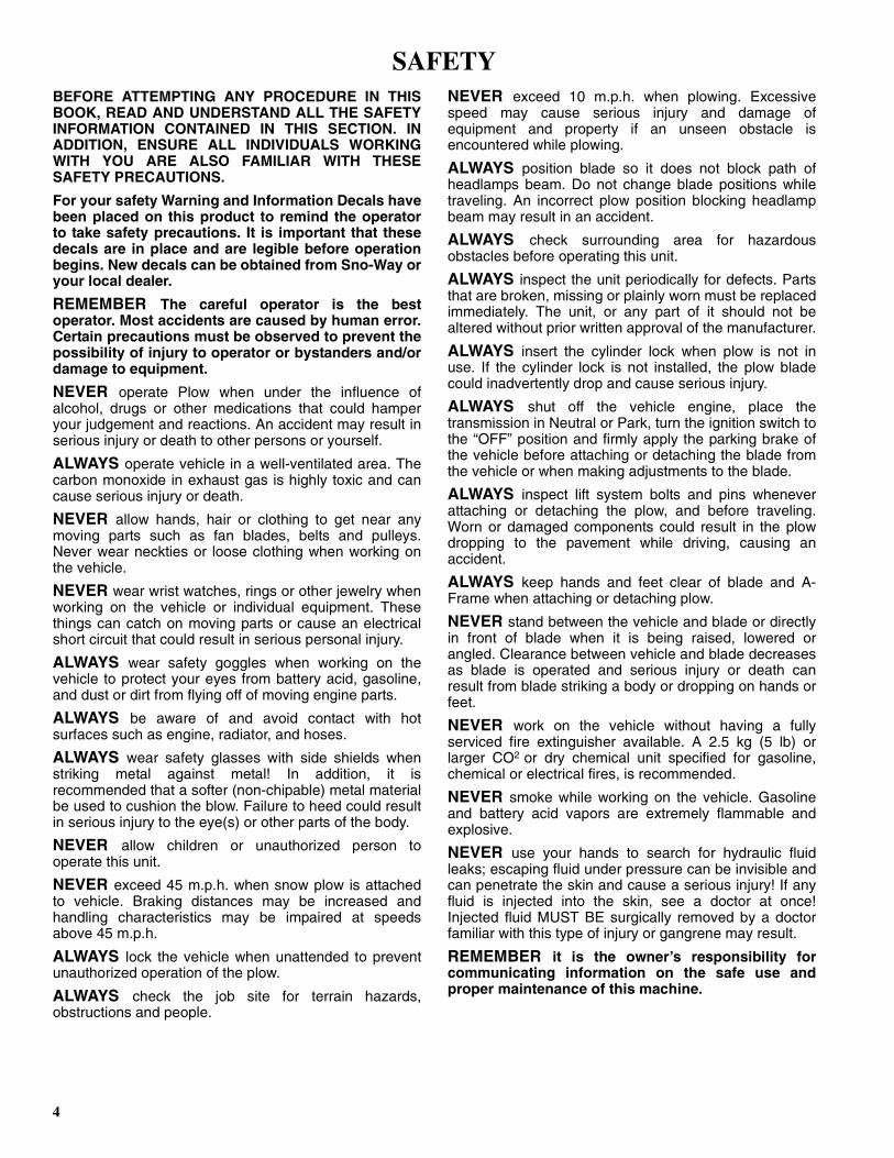
3. With the 6-pin in-circuit programming pins positioned on the top of the unit (See Figure 1-1), slide the receivermodule into the receiver mounting channel with theexposed wires of the receiver box positioned toward thehydraulic reservoir (See Figure 1-2).
Figure 1-1
Figure 1-2
4. Re-install the cap screw and nylock nut previously removed.
5. Connect the 14 terminal connector on the receiver module to the snow plow power pack. On 29VHD,Revolution and R Models only, also connect the four (4)terminal connector on the receiver to the connector onthe snow plow power pack..
Receiver Installation on Salt Spreader
6 & 9 Cubic Foot Spreaders
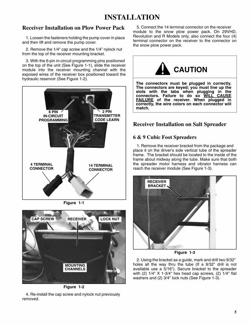
1. Remove the receiver bracket from the package and place it on the driver's side vertical tube of the spreaderframe. The bracket should be located to the inside of theframe about midway along the tube. Make sure that boththe spreader motor harness and vibrator harness canreach the receiver module (See Figure 1-3).
Figure 1-3
2. Using the bracket as a guide, mark and drill two 9/32" holes all the way thru the tube (If a 9/32" drill is notavailable use a 5/16"). Secure bracket to the spreaderwith (2) 1/4" X 1-3/4" hex head cap screws, (2) 1/4" flatwashers and (2) 3/4" lock nuts (See Figure 1-3).
4 TERMINALCONNECTOR
14 TERMINALCONNECTOR
2 PINTRANSMITTERCODE LEARN
6 PININ-CIRCUIT
PROGRAMMING
RECEIVERCAP SCREW LOCK NUT
MOUNTINGCHANNELS
CAUTION
The connectors must be plugged in correctly.The connectors are keyed; you must line up theslots with the tabs when plugging in theconnectors. Failure to do so WILL CAUSEFAILURE of the receiver. When plugged incorrectly, the wire colors on each connector willmatch.
RECEIVERBRACKET
INSTALLATION
6
3. Slide the receiver into the bracket with the 6-Pin in circuit programing pins located vertically in the open endof the bracket. Secure the receiver with a ¼" x 6" hexhead cap screw and a ¼" lock nut (See Figure 1-4).
Figure 1-4
4. Plug the spreader spinner motor harness and vibrator harness (optional) into the mating plugs on the receiver.
4 Cubic Foot Spreader
1. Remove the receiver bracket from the package and place it under the top lip of the spreader hoper on thedriver's side (See Figure 1-5).
Figure 1-5
2. Secure the receiver by driving (2) 5/16" self-drilling screws thru the holes in the bracket and into the hopper.
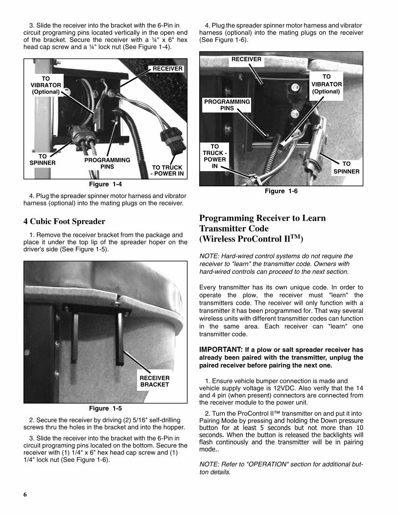
3. Slide the receiver into the bracket with the 6-Pin in circuit programing pins located on the bottom. Secure thereceiver with (1) 1/4" x 6" hex head cap screw and (1)1/4" lock nut (See Figure 1-6).
4. Plug the spreader spinner motor harness and vibrator harness (optional) into the mating plugs on the receiver(See Figure 1-6).
Figure 1-6
Programming Receiver to Learn Transmitter Code(Wireless ProControl IlTM)
NOTE: Hard-wired control systems do not require the receiver to "learn" the transmitter code. Owners with hard-wired controls can proceed to the next section.
Every transmitter has its own unique code. In order tooperate the plow, the receiver must "learn" thetransmitters code. The receiver will only function with atransmitter it has been programmed for. That way severalwireless units with different transmitter codes can functionin the same area. Each receiver can "learn" onetransmitter code.
IMPORTANT: If a plow or salt spreader receiver hasalready been paired with the transmitter, unplug thepaired receiver before pairing the next one.
1. Ensure vehicle bumper connection is made and vehicle supply voltage is 12VDC. Also verify that the 14and 4 pin (when present) connectors are connected fromthe receiver module to the power unit.
2. Turn the ProControl II™ transmitter on and put it into Pairing Mode by pressing and holding the Down pressurebutton for at least 5 seconds but not more than 10seconds. When the button is released the backlights willflash continously and the transmitter will be in pairingmode..
NOTE: Refer to "OPERATION" section for additional but-ton details.
RECEIVER
TOSPINNER PROGRAMMING
PINS
TOVIBRATOR(Optional)
TO TRUCK- POWER IN
RECEIVERBRACKET
TO
(Optional)VIBRATOR
RECEIVER
TOTRUCK -POWER
IN
PROGRAMMINGPINS
TOSPINNER

7
3. Place metal object across the 2 pin Transmitter Code Learn contacts on the receiver module. (See Figure 1-1).Remove the object and the LED on the receiver willalternately flash green and red three times. The LED willthen flash red continuously to indicate the receiver is inpairing mode.
4. When the receiver and transmitter are paired the light on the down pressure button will flash three timesand the LED on the receiver will change from flashing redto flashing green. When this happens push the downpressure button to exit pairing mode.
5. For best results it is recomended that you turn the Pro Control 2 transmitter and receiver off and then backon after pairing. To turn the receiver off simply unplugthe plow power harness, wait 10 seconds, and then plugit back in.
NOTE: Each transmitter can be paired to one plow receiver and one salt spreader receiver at the same time. The pairing process is the same for either receiver.
Control Harness Installation On Plow(Hard-Wired ProControl IITM)
NOTE: Wireless control systems do not require the control harness to be installed. Wireless owners may go back to the previous section.
1. Remove the wire harness components from the bag of harness parts included in the control package.
2. Run the 4 wire harness on the receiver unit over to the main power harness. Zip tie where necessary to themain power harness. Ensure the control wire harness isrouted in the power harness clamp and continue runningwith the main power harness. Leave enough room toconnect harness to vehicle harness. Ensure the cable isclear of pinch points and latching mechanism. Anyexcess cabling should be kept and zip tied under thepump cover (See Figure 1-7 & 1-8).
Figure 1-7
Figure 1-8
NOTE: This system has no separate storage cap. It does have a male and female connector combination that allows for convenient storage when the plow is not in use. Simply plug the male and female connectors together for storage.
3. Determine a routing for the 12 ft. long harness from the vehicle bumper at the driver side of the power packthrough the vehicle engine compartment to the cab of thevehicle.
4. Look for an existing hole with a rubber grommet in the vehicle firewall. The hole must be 3/8” diameter orlarger.
5. If an existing 3/8” hole is not available, look for an area to drill that satisfies these conditions:
• DO NOT put a hole in such a spot that will force the wiring harness, when installed, to interfere or berouted behind accelerator pedal, brake pedal, clutchpedal, parking brake or associated linkage.
NOTE: If the hole has to be drilled through carpeting and/or insulation pull carpet and/or insulation back and out of the way. After hole has been drilled, mark back side of carpet and/or insulation where harness will pass through. Mark location to be cut with a "X" then, using a sharp util-ity knife, cut along the "X". Route harness through drilled hole and cut in carpet and/or insulation. Reinstall carpet and/or insulation. This will allow for a clean repair should the plow ever be removed. Simply place a piece of duct tape on the back side of the carpet and press into place. This will virtually hide the cut in the carpet where the har-ness was routed.
MAINHARNESS
CAUTION
DO NOT drill any holes until a thorough visualinspection is performed to determine that thearea around the hole to be drilled, on both sidesof the firewall, is clear of any obstacles such asbrake lines, linkage or vehicle wiring.
CLAMPMAIN
HARNESS
8
6. Drill a 3/8” hole through the vehicle firewall.
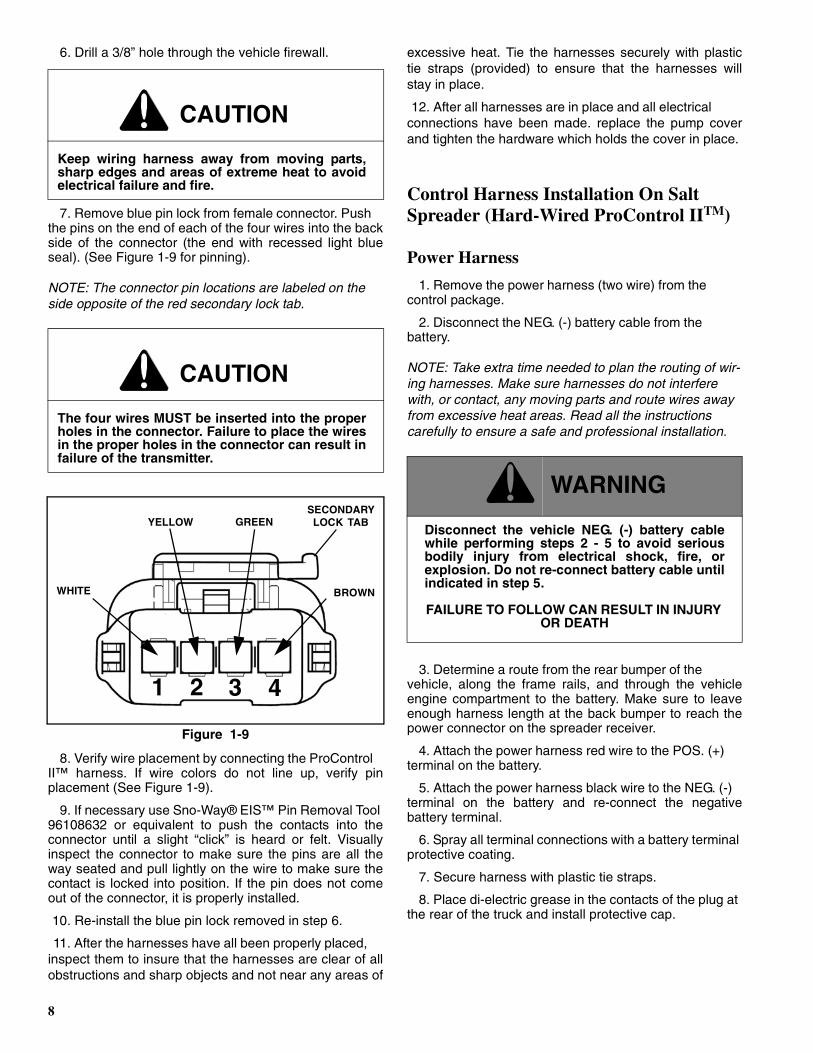
7. Remove blue pin lock from female connector. Push the pins on the end of each of the four wires into the backside of the connector (the end with recessed light blueseal). (See Figure 1-9 for pinning).
NOTE: The connector pin locations are labeled on the side opposite of the red secondary lock tab.
Figure 1-9
8. Verify wire placement by connecting the ProControl II™ harness. If wire colors do not line up, verify pinplacement (See Figure 1-9).
9. If necessary use Sno-Way® EIS™ Pin Removal Tool 96108632 or equivalent to push the contacts into theconnector until a slight “click” is heard or felt. Visuallyinspect the connector to make sure the pins are all theway seated and pull lightly on the wire to make sure thecontact is locked into position. If the pin does not comeout of the connector, it is properly installed.
10. Re-install the blue pin lock removed in step 6.
11. After the harnesses have all been properly placed, inspect them to insure that the harnesses are clear of allobstructions and sharp objects and not near any areas of
excessive heat. Tie the harnesses securely with plastictie straps (provided) to ensure that the harnesses willstay in place.
12. After all harnesses are in place and all electrical connections have been made. replace the pump coverand tighten the hardware which holds the cover in place.
Control Harness Installation On Salt Spreader (Hard-Wired ProControl IITM)
Power Harness
1. Remove the power harness (two wire) from the control package.
2. Disconnect the NEG. (-) battery cable from the battery.
NOTE: Take extra time needed to plan the routing of wir-ing harnesses. Make sure harnesses do not interfere with, or contact, any moving parts and route wires away from excessive heat areas. Read all the instructions carefully to ensure a safe and professional installation.
3. Determine a route from the rear bumper of the vehicle, along the frame rails, and through the vehicleengine compartment to the battery. Make sure to leaveenough harness length at the back bumper to reach thepower connector on the spreader receiver.
4. Attach the power harness red wire to the POS. (+) terminal on the battery.
5. Attach the power harness black wire to the NEG. (-) terminal on the battery and re-connect the negativebattery terminal.
6. Spray all terminal connections with a battery terminal protective coating.
7. Secure harness with plastic tie straps.
8. Place di-electric grease in the contacts of the plug at the rear of the truck and install protective cap.
CAUTION
Keep wiring harness away from moving parts,sharp edges and areas of extreme heat to avoidelectrical failure and fire.
CAUTION
The four wires MUST be inserted into the properholes in the connector. Failure to place the wiresin the proper holes in the connector can result infailure of the transmitter.
WHITE
1 32 4
YELLOW GREEN
BROWN
SECONDARYLOCK TAB
c WARNING
Disconnect the vehicle NEG. (-) battery cablewhile performing steps 2 - 5 to avoid seriousbodily injury from electrical shock, fire, orexplosion. Do not re-connect battery cable untilindicated in step 5.
FAILURE TO FOLLOW CAN RESULT IN INJURY OR DEATH
9
Control Harness
1. Remove the control harness (4 wire) and wire harness components parts bag from the control package.
2. Determine a routing from the rear bumper of the truck, along the frame rails, through the enginecompartment, and to the cab of the vehicle.
3. Look for an existing hole with a rubber grommet in the vehicle firewall. The hole must be 3/8” diameter orlarger.
4. If an existing 3/8” hole is not available, look for an area to drill that satisfies these conditions:
• DO NOT put a hole in such a spot that will force the wiring harness, when installed, to interfere or berouted behind accelerator pedal, brake pedal, clutchpedal, parking brake or associated linkage.
NOTE: If the hole has to be drilled through carpeting and/or insulation pull carpet and/or insulation back and out of the way. After hole has been drilled, mark back side of carpet and/or insulation where harness will pass through. Mark location to be cut with a "X" then, using a sharp util-ity knife, cut along the "X". Route harness through drilled hole and cut in carpet and/or insulation. Reinstall carpet and/or insulation. This will allow for a clean repair should the plow ever be removed. Simply place a piece of duct tape on the back side of the carpet and press into place. This will virtually hide the cut in the carpet where the har-ness was routed.
5. Drill a 3/8” hole through the vehicle firewall.
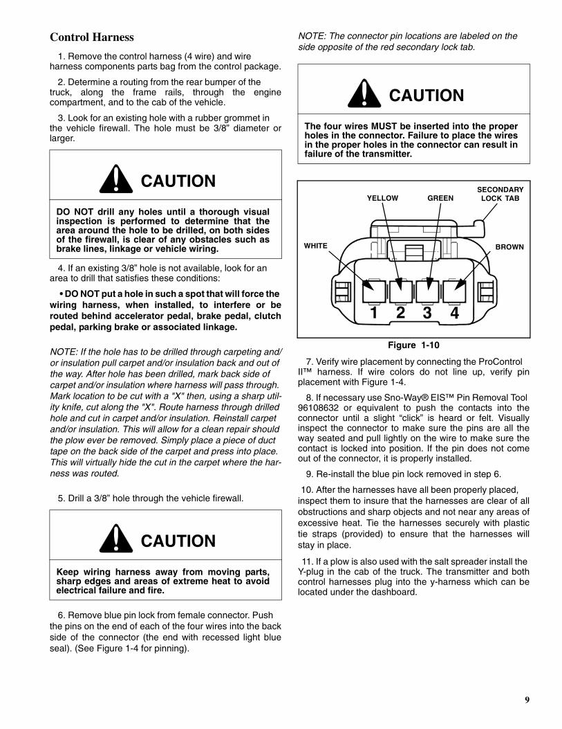
6. Remove blue pin lock from female connector. Push the pins on the end of each of the four wires into the backside of the connector (the end with recessed light blueseal). (See Figure 1-4 for pinning).
NOTE: The connector pin locations are labeled on the side opposite of the red secondary lock tab.
Figure 1-10
7. Verify wire placement by connecting the ProControl II™ harness. If wire colors do not line up, verify pinplacement with Figure 1-4.
8. If necessary use Sno-Way® EIS™ Pin Removal Tool 96108632 or equivalent to push the contacts into theconnector until a slight “click” is heard or felt. Visuallyinspect the connector to make sure the pins are all theway seated and pull lightly on the wire to make sure thecontact is locked into position. If the pin does not comeout of the connector, it is properly installed.
9. Re-install the blue pin lock removed in step 6.
10. After the harnesses have all been properly placed, inspect them to insure that the harnesses are clear of allobstructions and sharp objects and not near any areas ofexcessive heat. Tie the harnesses securely with plastictie straps (provided) to ensure that the harnesses willstay in place.
11. If a plow is also used with the salt spreader install the Y-plug in the cab of the truck. The transmitter and bothcontrol harnesses plug into the y-harness which can belocated under the dashboard.
CAUTION
DO NOT drill any holes until a thorough visualinspection is performed to determine that thearea around the hole to be drilled, on both sidesof the firewall, is clear of any obstacles such asbrake lines, linkage or vehicle wiring.
CAUTION
Keep wiring harness away from moving parts,sharp edges and areas of extreme heat to avoidelectrical failure and fire.
CAUTION
The four wires MUST be inserted into the properholes in the connector. Failure to place the wiresin the proper holes in the connector can result infailure of the transmitter.
WHITE
1 32 4
YELLOW GREEN
BROWN
SECONDARYLOCK TAB
10
Theory of Operation
1. The Sno-Way ProControl II™ Operating System includes two key components. The first is a hand heldtransmitter. When a switch is actuated, the ProControlII™ transmitter sends a signal out to the snow plowthrough the plow control harness indicating whichoperation is to be performed, such as ‘Raise’, ‘SwingRight’ and ‘DP On’.
2. The second key part of the ProControl II™ system is the receiver module on the plow. It receives the signalfrom the ProControl II™ transmitter and processes thesignal to open or close valves on or off so that thehydraulic system of the plow power unit will perform therequired operations.
3. 12V DC power is fed from the battery terminal of the start solenoid to the individual valve solenoid coils andthe receiver module. The ground wires for the startsolenoid primary circuit and the coils of the valvesolenoids return to the circuit board of the receiver whereswitches on the circuit board open or close the ground tocomplete or break the circuit to each coil and solenoid.
NOTE: This is a ground switching system and has power on the coils as soon as power is connected to the plow. The receiver module energizes the coils by providing a ground path to them.
4. On wired ProControl II™ systems, a low voltage power circuit leads from the receiver to the ProControlII™ transmitter. This powers the circuit board of theProControl II™ transmitter and supplies the low voltagepower needed to process the signal from the switches onthe transmitter and send a signal back to the receiver onthe plow.
ProControl II™ OperationBasic Functions – All Plows
The ProControl II™ transmitter contains all of the controlfunctions necessary for the operation of your Sno-Waysnow plow and receiver mounted salt spreader.
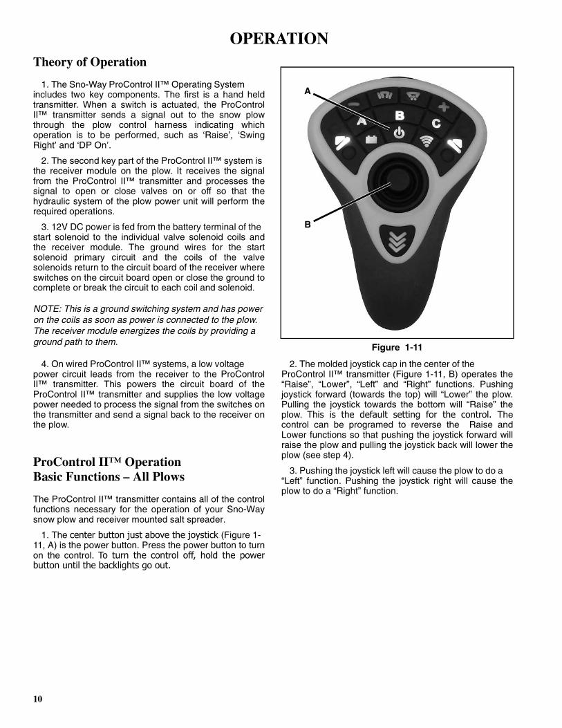
1. The center button just above the joystick (Figure 1-11, A) is the power button. Press the power button to turnon the control. To turn the control off, hold the powerbutton until the backlights go out.
Figure 1-11
2. The molded joystick cap in the center of the ProControl II™ transmitter (Figure 1-11, B) operates the“Raise”, “Lower”, “Left” and “Right” functions. Pushingjoystick forward (towards the top) will “Lower” the plow.Pulling the joystick towards the bottom will “Raise” theplow. This is the default setting for the control. Thecontrol can be programed to reverse the Raise andLower functions so that pushing the joystick forward willraise the plow and pulling the joystick back will lower theplow (see step 4).
3. Pushing the joystick left will cause the plow to do a “Left” function. Pushing the joystick right will cause theplow to do a “Right” function.
A
B
OPERATION
11
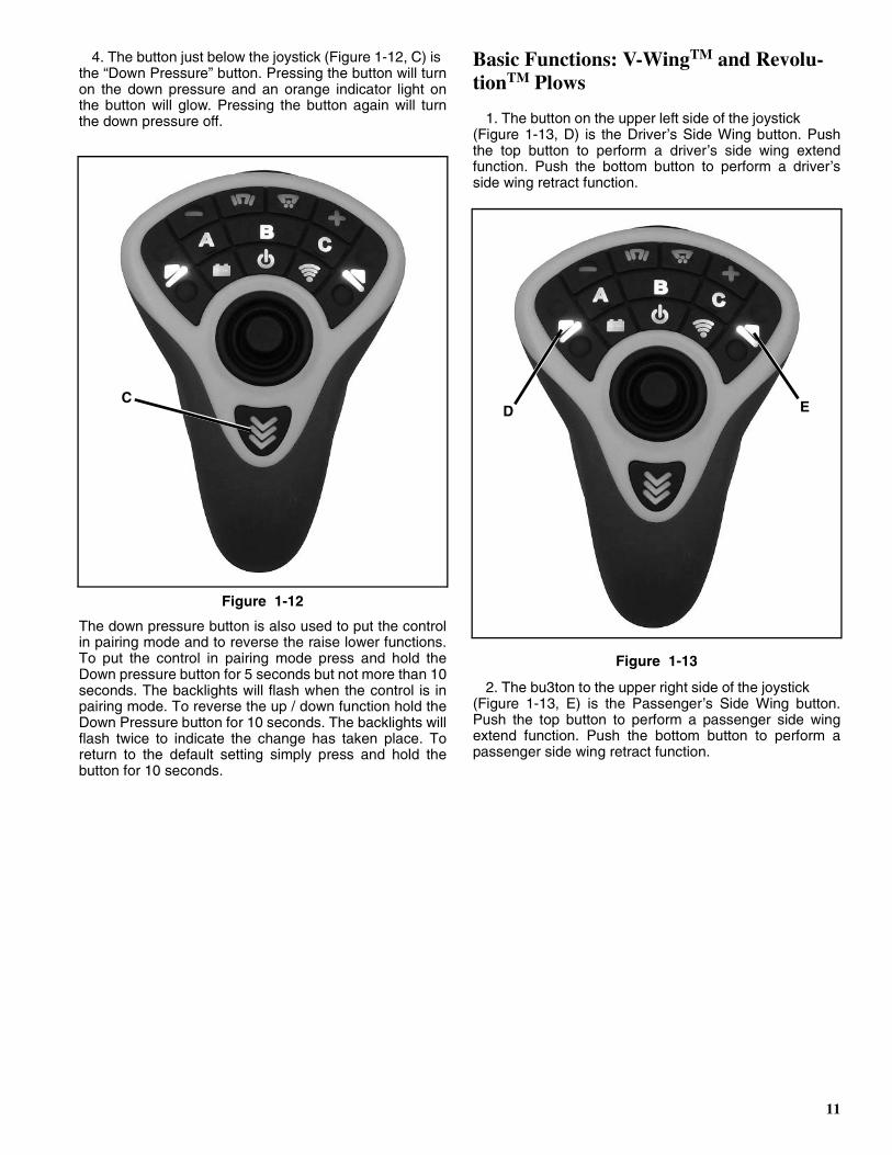
4. The button just below the joystick (Figure 1-12, C) is the “Down Pressure” button. Pressing the button will turnon the down pressure and an orange indicator light onthe button will glow. Pressing the button again will turnthe down pressure off.
Figure 1-12
The down pressure button is also used to put the controlin pairing mode and to reverse the raise lower functions.To put the control in pairing mode press and hold theDown pressure button for 5 seconds but not more than 10seconds. The backlights will flash when the control is inpairing mode. To reverse the up / down function hold theDown Pressure button for 10 seconds. The backlights willflash twice to indicate the change has taken place. Toreturn to the default setting simply press and hold thebutton for 10 seconds.
Basic Functions: V-WingTM and Revolu-tionTM Plows
1. The button on the upper left side of the joystick (Figure 1-13, D) is the Driver’s Side Wing button. Pushthe top button to perform a driver’s side wing extendfunction. Push the bottom button to perform a driver’sside wing retract function.
Figure 1-13
2. The bu3ton to the upper right side of the joystick (Figure 1-13, E) is the Passenger’s Side Wing button.Push the top button to perform a passenger side wingextend function. Push the bottom button to perform apassenger side wing retract function.
CD E
12
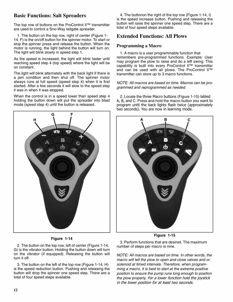
Basic Functions: Salt Spreaders
The top row of buttons on the ProControl II™ transmitterare used to control a Sno-Way tailgate spreader.
1. The button on the top row, right of center (Figure 1-14, F) is the on/off button for the spinner motor. To start orstop the spinner press and release the button. When themotor is running, the light behind the button will turn on.The light will blink slowly in speed step 1.
As the speed is increased, the light will blink faster untilreaching speed step 4 (top speed) where the light will beon constant.
The light will blink alternately with the back light if there isa jam condition and then shut off. The spinner motoralways runs at full speed (speed step 4) when it is firststarted. After a few seconds it will slow to the speed stepit was in when it was stopped.
When the control is in a speed lower than speed step 4holding the button down will put the spreader into blastmode (speed step 4) until the button is released.
Figure 1-14
2. The button on the top row, left of center (Figure 1-14, G) is the vibrator button. Holding the button down will turnon the vibrator (if equipped). Releasing the button willturn it off.
3. The button on the left of the top row (Figure 1-14, H) is the speed reduction button. Pushing and releasing thebutton will drop the spinner one speed step. There are atotal of four speed steps available.
4. The buttonon the right of the top row (Figure 1-14, I) is the speed increase button. Pushing and releasing thebutton will raise the spinner one speed step. There are atotal of four speed steps available.
Extended Functions: All Plows
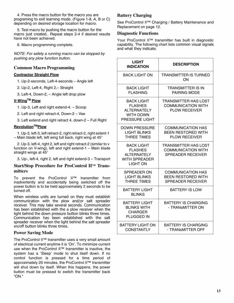
Programming a Macro
1. A macro is a user programmable function that remembers pre-programmed functions. Example: Usermay program the plow to raise and do a left swing. Thiscapability is built into every ProControl II™ transmitterand can be used with all plows. The ProControl II™transmitter can store up to 3 macro functions.
NOTE: All macros are based on time. Macros can be pro-grammed and reprogrammed as needed.
2. Locate the three Macro buttons (Figure 1-15) labled A, B, and C. Press and hold the macro button you want toprogram until the back lights flash twice (approximatelytwo seconds). You are now in learning mode.
Figure 1-15
3. Perform functions that are desired. The maximum number of steps per macro is nine.
NOTE: All macros are based on time. In other words, the macro will tell the plow to open and close valves and or solenoid at timed intervals. Therefore, when program-ming a macro, it is best to start at the extreme positive position to ensure the pump runs long enough to position the plow properly. For a lower function hold the joystick in the lower position for at least two seconds.
H IG F
A CB
13
4. Press the macro button for the macro you are programing to exit learning mode. (Figure 1-8, A, B or C)depending on desired storage location for macro.
5. Test macro by pushing the macro button for the macro just created.. Repeat steps 2-4 if desired resultshave not been achieved.
6. Macro programming complete.
NOTE: For safety a running macro can be stopped by pushing any plow function button.
Common Macro Programming
Contractor Straight Plow
1. Up-2-seconds, Left-4-seconds – Angle left
2. Up-2, Left-4, Right 2,– Straight
3. Left-4, Down-2, – Angle left drop plow
V-WingTM Plow
1. Up-3, Left and right extend-4. – Scoop
2. Left and right retract-4, Down-2 – Vee
3. Left extend and right retract 4, down-2 – Full Right
RevolutionTMPlow
1. Up-3, left-3, left retract-2, right retract-2, right extent-1 – Main blade left, left wing full back, right wing at 45°
2. Up-3, left-4, right 2, left and right retract-2 (similar to v function on V-wing), left and right extend-1 – Main bladestraight wings at 45°
3. Up-, left-4, right 2, left and right extend-3 – Transport
Start/Stop Procedure for ProControl II™ Trans-mitters
To prevent the ProControl II™ transmitter frominadvertently and accidentally being switched off thepower button is to be held approximately 2 seconds to beturned off.
When wireless units are turned on they must establishcommunication with the plow and/or salt spreaderreceiver. This may take several seconds. Communicationhas been established with the a plow receiver when thelight behind the down pressure button blinks three times.Communication has been established with the saltspreader receiver when the light behind the salt spreaderon/off button blinks three times.
Power Saving Mode
The ProControl II™ transmitter uses a very small amountof electrical current anytime it is ’On’. To minimize currentuse when the ProControl II™ transmitter is inactive, thesystem has a ’Sleep’ mode to shut itself down. If nocontrol function is pressed for a time period ofapproximately 20 minutes, the ProControl II™ transmitterwill shut down by itself. When this happens, the powerbutton must be pressed to switch the transmitter back"ON."
Battery Charging
See ProControl II™ Charging / Battery Maintenance andReplacement on page 12.
Diagnostic Functions
Your ProControl II™ transmitter has built in diagnosticcapability. The following chart lists common visual signalsand what they indicate.
LIGHTINDICATION
DESCRIPTION
BACK LIGHT ON TRANSMITTER IS TURNED ON
BACK LIGHT FLASHING
TRANSMITTER IS IN PAIRING MODE
BACK LIGHT FLASHES
ALTERNATELY WITH DOWN
PRESSURE LIGHT
TRANSMITTER HAS LOST COMMUNICATION WITH
PLOW RECEIVER
DOWN PRESSURE LIGHT BLINKS THREE TIMES
COMMUNICATION HAS BEEN RESTORED WITH
PLOW RECEIVER
BACK LIGHT FLASHES
ALTERNATELY WITH SPREADER
LIGHT ON
TRANSMITTER HAS LOST COMMUNICATION WITH SPREADER RECEIVER
SPREADER ON LIGHT BLINKS THREE TIMES
COMMUNICATION HAS BEEN RESTORED WITH SPREADER RECEIVER
BATTERY LIGHT BLINKS
BATTERY IS LOW
BATTERY LIGHT BLINKS WITH
CHARGER PLUGGED IN
BATTERY IS CHARGING- TRANsMITTER ON
BATTERY LIGHT ON CONSTANTLY
BATTERY IS CHARGING- TRANsMITTER OFF
14
ProControl IITM Charging / BatteryMaintenance and Replacement
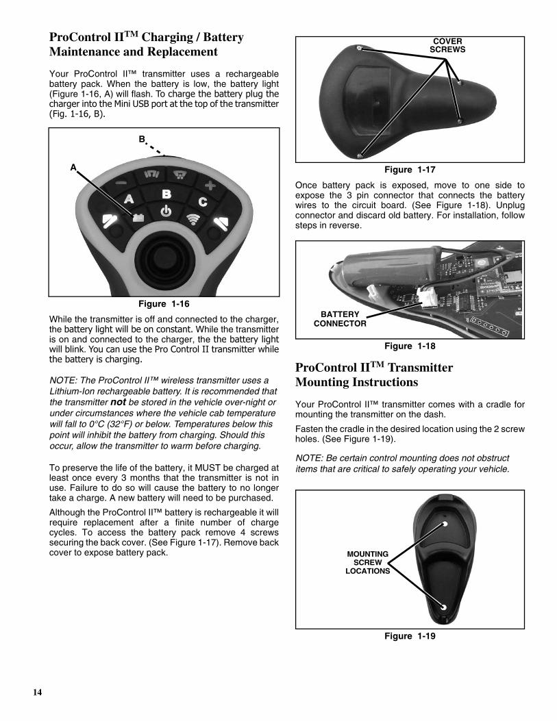
Your ProControl II™ transmitter uses a rechargeablebattery pack. When the battery is low, the battery light(Figure 1-16, A) will flash. To charge the battery plug thecharger into the Mini USB port at the top of the transmitter(Fig. 1-16, B).
Figure 1-16
While the transmitter is off and connected to the charger,the battery light will be on constant. While the transmitteris on and connected to the charger, the the battery lightwill blink. You can use the Pro Control II transmitter whilethe battery is charging.
NOTE: The ProControl II™ wireless transmitter uses a Lithium-Ion rechargeable battery. It is recommended that the transmitter not be stored in the vehicle over-night or under circumstances where the vehicle cab temperature will fall to 0°C (32°F) or below. Temperatures below this point will inhibit the battery from charging. Should this occur, allow the transmitter to warm before charging.
To preserve the life of the battery, it MUST be charged atleast once every 3 months that the transmitter is not inuse. Failure to do so will cause the battery to no longertake a charge. A new battery will need to be purchased.
Although the ProControl II™ battery is rechargeable it willrequire replacement after a finite number of chargecycles. To access the battery pack remove 4 screwssecuring the back cover. (See Figure 1-17). Remove backcover to expose battery pack.
Figure 1-17
Once battery pack is exposed, move to one side toexpose the 3 pin connector that connects the batterywires to the circuit board. (See Figure 1-18). Unplugconnector and discard old battery. For installation, followsteps in reverse.
Figure 1-18
ProControl IITM TransmitterMounting Instructions
Your ProControl II™ transmitter comes with a cradle formounting the transmitter on the dash.
Fasten the cradle in the desired location using the 2 screwholes. (See Figure 1-19).
NOTE: Be certain control mounting does not obstruct items that are critical to safely operating your vehicle.
Figure 1-19
A
B
COVERSCREWS
BATTERYCONNECTOR
MOUNTINGSCREW
LOCATIONS

15
Using the ProControl IITM to Aid in Mounting and Removing the Snow Plow
The ProControl II™ transmitter can be used near thesnow plow when mounting or removing the plow with theaid of the power jackstand.
NOTE: For proper procedure in mounting and removal of the snow plow, refer to your Sno-Way Plow Owner’s Manual.
For Hard-Wired Units
Disconnect the cable for the ProControl II™ transmitter atthe harness connection inside the vehicle cab and takethe controller to the front of the vehicle. Disconnect theplow control harness from the vehicle control harness atthe connector at the front of the vehicle. Connect theProControl II™ transmitter to the plow control harness.The ProControl II™ transmitter can now be used just as itis normally used in the cab of the vehicle.
When plow mounting or removal is completed, reconnectthe ProControl II™ transmitter to the vehicle harnessconnector in the cab.
For Wireless Units
Remove the ProControl II™ transmitter from the cab,carry it to the front of the truck and use normally.
Storage (Hard-wired ProControl II™)
Your receiver module is equipped with male and femaleconnectors. When power is no longer connected to theplow, plug the male into the female connector for storage.
Your vehicle harness is also equipped with male andfemale connectors. Once the plow is disconnected, plugthe male into the female connector for storage.
Wiring Schematics
ProControl II™ system schematic diagrams are located inyour products Installation & Owner’s Manual.
ProControl II™ Battery Warranty
The ProControl II™ rechargeable battery has a 1 yearlimited warranty. If Sno-Way finds that any part wasdefective in material or workmanship, we will replace itwith a new battery at no charge to you. Proof of originalpurchase date is required. This warranty does not coverbatteries that have been improperly installed, maintainedor repaired, or batteries that have been subject to misuse,abuse, accident, physical damage, abnormal operation,abnormal handling, neglect, and exposure to fire or water.Some exclusion applies.
WARNING
When using the ProControl II™ transmitternear the plow, be especially careful of themovement of any plow components when anyswitch on the transmitter is actuated. Standclear of the snow plow at all times to avoidbeing struck by any plow parts.
FAILURE TO FOLLOW CAN RESULT IN INJURY OR DEATH.

Hartford, WI 53027 USA Website: www.snoway.com©2013 Sno-Way® International
SNO-WAY® INTERNATIONAL, INC.