1201 TCC: Feeder breaker is not coordinated with the HV ...Appendix A of this supplemental report...
54
Shippensburg University 1871 Old Main Drive Shippensburg, PA 17257 SUPPLEMENT 1 Electrical Coordination Study August 24, 2004 Professional: Entech Engineering, Inc. 4 South Fourth Street P.O. Box 32 Reading, PA 19603 Telephone: 610-373-6667 Fax: 610-373-7537 www.entecheng.com Entech Project #: 2184.22
Transcript of 1201 TCC: Feeder breaker is not coordinated with the HV ...Appendix A of this supplemental report...
Shippensburg University 1871 Old Main Drive
Shippensburg, PA 17257
SUPPLEMENT 1 Electrical Coordination Study
August 24, 2004
Professional: Entech Engineering, Inc. 4 South Fourth Street P.O. Box 32 Reading, PA 19603 Telephone: 610-373-6667 Fax: 610-373-7537 www.entecheng.com
Entech Project #: 2184.22

Electrical Coordination Study Table of Contents
EXECUTIVE SUMMARY ................................................................................................ 1
INTRODUCTION............................................................................................................. 2
DISCUSSION.................................................................................................................. 2
RECOMMENDATIONS................................................................................................... 3
CONCLUSIONS.............................................................................................................. 7
Appendix A – Existing Curves
Appendix B – Recommended Curves
Shippensburg University TOC Entech Engineering, Inc. Electrical Coordination Study Entech #2184.22

EXECUTIVE SUMMARY
As a supplement to the Shippensburg University Medium Voltage Distribution Study conducted
by Entech Engineering Inc., the coordination of the medium voltage distribution system was
analyzed. Time current curves (TCC’s) used in this analysis are included in Appendix A of this
report. The names of these TCC’s coincide with feeder or building and transformer names as
indicated on the site plans and single-line diagrams included with the main report. This analysis
revealed that, in general, the system over-current protection is coordinated. However, there are
several areas of concern where coordination can be improved.
Setting Adjustments
Coordination in the following areas of the system can be corrected by adjusting settings on
relays and circuit breakers, or replacing fuses:
1. TCC 1201 2. TCC1202 3. TCC1203 4. TCC 1204 5. TCC TR1-1 McCune Hall 6. TCC TR3-4 Franklin Science Center
Appendix B of this supplement contains TCC’s that indicate these device adjustments. The cost
of making these corrections is estimated to be $6,500.
Upgrade or Replacement
Other areas will require upgrade or replacement of over-current devices or equipment. These
areas are as follows:
1. TCC TR1-3 Henderson Gym 2. TCC TR1-9 Tennis Courts & Multi Use Field 3. TCC TR2-8 Cora Grove Spiritual Center 4. TCC TR3-1 Ezra Lehman Library 5. TCC TR4-5 Cumberland Student Union
The approximate cost to upgrade this equipment is $75,000.
Shippensburg University 1 Entech Engineering, Inc. Electrical Coordination Study Entech #2184.22

INTRODUCTION
Entech Engineering, Inc. was asked to analyze the 12.47kV medium voltage distribution system
at Shippensburg University. As a supplement to that analysis, a coordination study of the
system’s protective devices was completed with information attained as part of that analysis.
The following is a discussion of the findings and recommendations that resulted from the
coordination study. The majority of the information for this study came from Entech’s field
surveys. However, since the system was energized at the time of the surveys and some
devices could not be accessed, the University’s electrical staff assisted with data collection.
DISCUSSION
Appendix A of this supplemental report contains time current curves (TCC’s) for each of the
system’s main feeders (1201, 1202, 1203, and 1204) and each transformer serving Campus
buildings (Old Main, Franklin Science Center, etc.). The TCC’s for each feeder typically indicate
the following:
1. TCC for the associated Main Substation bus circuit breaker over-current relay #1 or #2.
2. TCC for the feeder circuit breaker over-current relay. 3. TCC for the largest over-current device (fuse, circuit breaker, etc) on the feeder.
In some cases additional information, such as the inrush current point for the largest transformer
on the feeder, was also shown based on importance to the analysis.
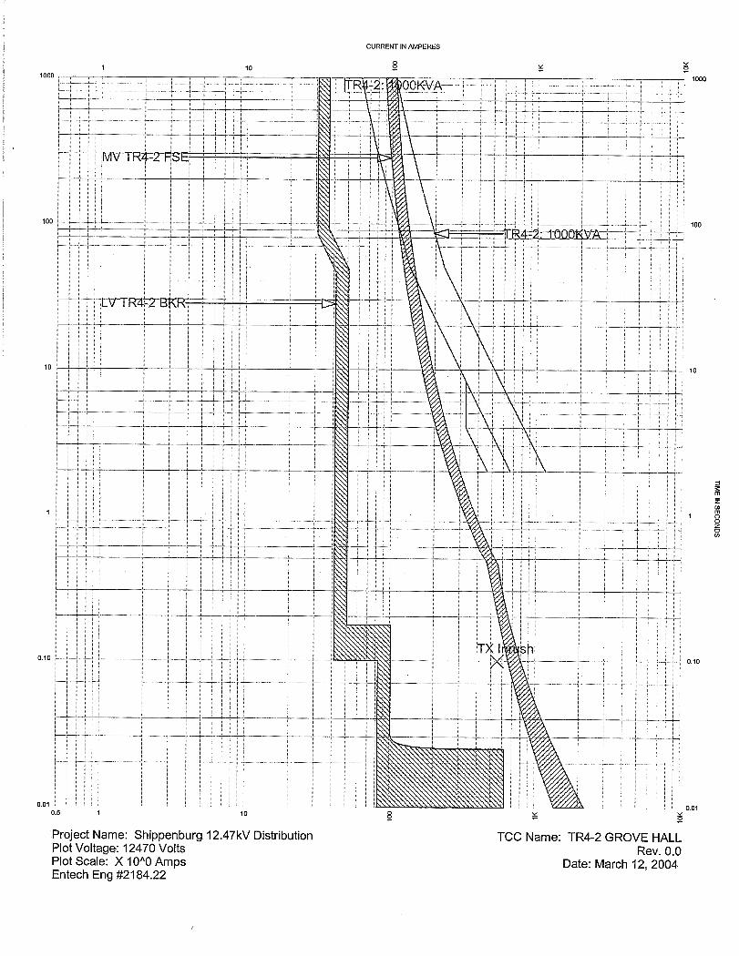
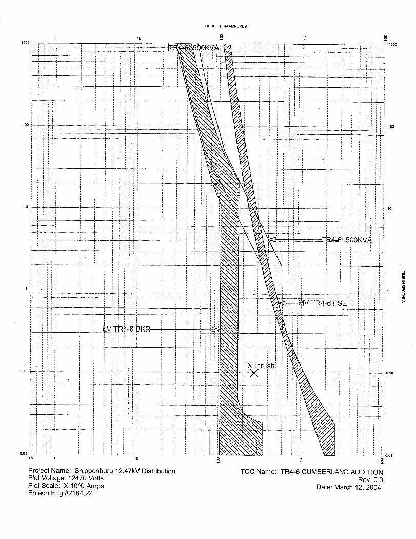
The TCC’s for each of the Campus building transformers generally indicate the following:
1. TCC for the primary over-current device (typically fuses). 2. TCC for the secondary main over-current device (typically a circuit breaker). 3. Transformer damage curves (these are modeled based on industry standards, rated
input impedance, and temperature rating).
Upon review of the TCC’s it appears in some cases that the primary protective device doesn’t
protect the transformer because it is not entirely “left” of the transformer damage curve,
especially in the “longtime” (overload) region of the TCC. These occurrences are not typically
highlighted as concerns in this report, since most every transformer on the system has only one
main secondary over-current protective device directly inline. If properly sized, this device
should clear overload faults caused by down stream loads. Only an overload fault between the
primary and secondary over-current protective devices can damage the transformer. Typically,
Shippensburg University 2 Entech Engineering, Inc. Electrical Coordination Study Entech #2184.22

a fault in this area of the system will be a direct phase-to-phase or phase-to-ground fault (short
circuit), and will likely be cleared by the primary device with out damage to the transformer.
Also, most of the primary over-current devices on each feeder are fuses with predetermined
(non-settable) curves. As result, the designer choosing fuses must pick a best-fit curve for
transformer protection without allowing nuisance tripping on the power up inrush current of the
transformer. For this reason, when cost is not of concern, many system designers will use a
protective device with settable curves, such as relay and circuit breakers.
The TCC’s in Appendix A indicate that the system is generally coordinated. There are,
however, some areas of concern that are discussed later in this report. In some cases these
issues are easily resolved by changing relay or breaker settings. In others, device or equipment
upgrades should be considered.
RECOMMENDATIONS
As mentioned above, there are some areas of concern throughout the system. The following is
a list the issues by TCC, as found in Appendix A. These TCC names coincide with feeder, or
building and transformer names, as indicated on the site plans and single-line diagrams
included with the main report. For each item, there is a brief discussion of the reason for
concern, followed by a recommendation for correction. Where a new TCC is relevant to the
recommendations for correction, a recommended TCC is included in Appendix B of this
supplement.
TCC 1201, TCC 1202, TCC 1203, TCC 1204: These curves show coordination between each of
the four main feeder relays, the upstream 12.47kV main bus relays, and the largest down
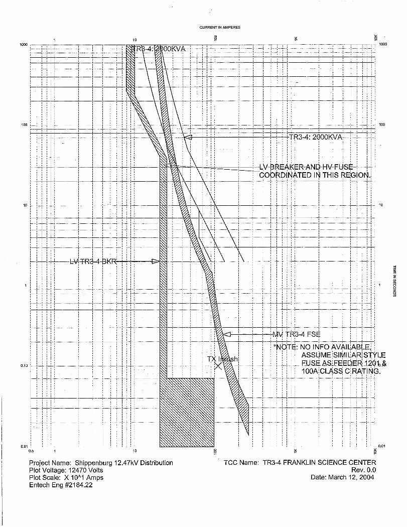
stream overcurrent device on each feeder. No information was available for the high voltage
fuses for the Franklin Science Center transformer (TR3-4) on feeder 1203. For the purposes of
this study, it was assumed that class C fuses similar to those found in outdoor transformers on
Feeder 1201 were used. A 100A fuse was chosen based on the transformer kVA rating
(2000kVA). Using this assumption and data collected from the field, the TCC’s indicate the
following coordination issues:
1. The feeder 1201 circuit breaker relay is not coordinated with the high voltage fuses for Horton Hall (TR1-4) in the short time and instantaneous area.
2. The feeder 1202 circuit breaker relay is not coordinated with the high voltage fuses for Old Main (TR2-9) in the short time and instantaneous areas.
Shippensburg University 3 Entech Engineering, Inc. Electrical Coordination Study Entech #2184.22
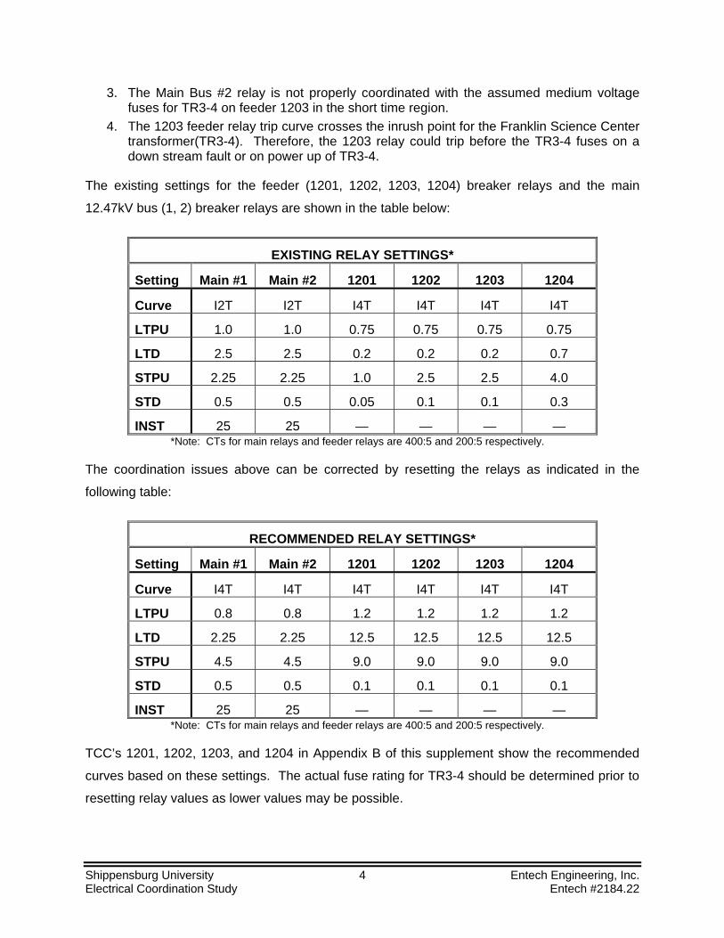
3. The Main Bus #2 relay is not properly coordinated with the assumed medium voltage fuses for TR3-4 on feeder 1203 in the short time region.
4. The 1203 feeder relay trip curve crosses the inrush point for the Franklin Science Center transformer(TR3-4). Therefore, the 1203 relay could trip before the TR3-4 fuses on a down stream fault or on power up of TR3-4.
The existing settings for the feeder (1201, 1202, 1203, 1204) breaker relays and the main
12.47kV bus (1, 2) breaker relays are shown in the table below:
EXISTING RELAY SETTINGS*
Setting Main #1 Main #2 1201 1202 1203 1204
Curve I2T I2T I4T I4T I4T I4T
LTPU 1.0 1.0 0.75 0.75 0.75 0.75
LTD 2.5 2.5 0.2 0.2 0.2 0.7
STPU 2.25 2.25 1.0 2.5 2.5 4.0
STD 0.5 0.5 0.05 0.1 0.1 0.3
INST 25 25 — — — — *Note: CTs for main relays and feeder relays are 400:5 and 200:5 respectively.
The coordination issues above can be corrected by resetting the relays as indicated in the
following table:
RECOMMENDED RELAY SETTINGS*
Setting Main #1 Main #2 1201 1202 1203 1204
Curve I4T I4T I4T I4T I4T I4T
LTPU 0.8 0.8 1.2 1.2 1.2 1.2
LTD 2.25 2.25 12.5 12.5 12.5 12.5
STPU 4.5 4.5 9.0 9.0 9.0 9.0
STD 0.5 0.5 0.1 0.1 0.1 0.1
INST 25 25 — — — — *Note: CTs for main relays and feeder relays are 400:5 and 200:5 respectively.
TCC’s 1201, 1202, 1203, and 1204 in Appendix B of this supplement show the recommended
curves based on these settings. The actual fuse rating for TR3-4 should be determined prior to
resetting relay values as lower values may be possible.
Shippensburg University 4 Entech Engineering, Inc. Electrical Coordination Study Entech #2184.22

Although the coordination issues above could be corrected without resetting the main 12.47kV
bus relay #1 and the feeder 1204 relay, it is recommended that both main 12.47kV bus relays
have the same settings and that the feeder relays have the same settings. This will help with
load balancing across all four feeders as new loads are added to the system and facilitates
coordination of the tie-breaker between the main 12.47kV buses. Also, it is important to note
that the recommended curve for the main 12.47kV bus relays is an I4T curve versus the original
I2T curve. I4T changes one decade of current over four decades of time. This curve fits
standard fuse curves more closely than the I2T curve, which changes one decade current over
two decades of time.
Changes to the medium voltage breaker relays should be completed by a certified relay testing
company that is capable of testing and verifying that the breakers trip at the proper overcurrent
levels.
TCC TR1-1 McCune Hall: Although the primary fuses for TR1-1 and secondary main breaker
are coordinated, the primary fuses do not properly protect the transformer. Using a 3A C rated
fuse instead of a 20A C rated fuse would improve transformer protection (refer to TCC TR1-1
McCune Hall in Appendix B). As far as secondary protection is concerned, replacement of the
secondary distribution panel should be considered based on age and configuration. A new
static trip (solid state) secondary main breaker with long-time, short-time, and instantaneous
pickup and delay settings is advised. This would allow greater flexibility in coordinating with the
upstream primary fuses.
TCC TR1-2 Reed Operations Center: The existing low voltage secondary main breaker is
reported to be Westinghouse 500A thermal magnetic breaker. This breaker does not coordinate
well with the primary fuse. To improve coordination, the existing thermal magnetic breaker
could be replaced with a static trip (solid state) main breaker with long-time, short-time, and
instantaneous pickup and delay settings. However, due to age of the existing equipment,
replacement of the existing unit substation and secondary distribution panel is recommended.
TCC TR1-3 Henderson Gym: The existing low voltage secondary main breaker is not
coordinated with the primary fuse. To improve coordination, the existing thermal magnetic
breaker could be replaced with a static trip (solid state) main breaker with long-time, short-time,
and instantaneous pickup and delay settings.
Shippensburg University 5 Entech Engineering, Inc. Electrical Coordination Study Entech #2184.22

TCC TR1-9 Tennis Courts and Multiuse Field: The existing low voltage secondary main
breaker is not coordinated with the primary fuse in the short time region. Coordination could be
improved by replacing the existing secondary main breaker with a static trip (solid state) main
breaker with long-time, short-time, and instantaneous pickup and delay settings.
TCC TR1-10 Shearer and Rowland: The existing C rated 20A primary fuse does not properly
protect the transformer TR1-10. According to University personnel, the service for Rowland and
Shearer Halls is being redesigned at this time. It is recommended that the primary protection for
the new service be selected to adequately protect the transformer. The new secondary of this
service should be provided with a static trip (solid state) main breaker with long-time, short-time,
and instantaneous pickup and delay settings to provide greater flexibility in coordinating with the
upstream devices.
TCC TR2-4 Wright Hall: The existing low voltage secondary main breaker is not coordinated
with the primary fuse in the short time region. Replacement of the secondary distribution panel
should be considered based on age and configuration. A new static trip (solid state) secondary
main breaker with long-time, short-time, and instantaneous pickup and delay settings is advised.
This would allow greater flexibility in coordinating with the upstream primary fuses.
TCC TR2-8 Cora Grove Spiritual Center: The actual size of primary fuses for TR2-8 could not
be determined during our surveys or form the information provided by the University. Therefore,
a fuse size and rating (class C, 12A) was assumed based on similarly sized transformers on the
campus. Based on analysis using this assumed data, the secondary main circuit breaker and
primary fuses for transformer TR2-8 are not coordinated in the short time region. Coordination
could be improved by replacing the existing secondary main breaker with a static trip (solid
state) main breaker with long-time, short-time, and instantaneous pickup and delay settings.
However, the actual rating of the primary fuses should be verified before any changes to the
system are made.
TCC TR3-1 Ezra Lehman Library: In the short time region, the secondary main circuit breaker
is not coordinated with the primary fuses for transformer TR3-1. This could result in the primary
fuses tripping before the secondary breaker on a down stream fault. A static trip (solid state)
breaker with long-time, short-time, and instantaneous pickup and delay settings could be
installed in place of the existing secondary main circuit breaker. The addition setting would
allow for better coordination with the up stream primary fuses.
Shippensburg University 6 Entech Engineering, Inc. Electrical Coordination Study Entech #2184.22
TCC TR3-4 Franklin Science Center: No information was available on the actual primary fuse
sizes and ratings. Therefore, a similar style fuse (class C) to those used elsewhere on Campus
was assumed with size (100A) based on the transformer kVA rating. With this assumed fuse
information, it is possible that the secondary main circuit breaker and primary fuses are not
coordinated. Better coordination may be achieved by resetting the following (refer to TCC TR3-
4 Franklin Science Center in Appendix B):
1. The longtime (LTD) setting from 24 to 12. 2. The instantaneous (INST) setting from 6 to 3.
Before changing any settings, the actual size of the primary fuses should be verified.
TCC TR4-5 The Cumberland Student: The main secondary circuit breaker and primary fuses
are not coordinated in the short time and long time regions. Although there is an instantaneous
pickup dial on the circuit breaker, there is not enough adjustment to coordinate it with the
primary fuses. Therefore, replacement of this breaker is recommended. A static trip (solid state)
breaker with long-time, short-time, and instantaneous pickup and delay settings could be
installed in place of the existing secondary main circuit breaker. A static trip breaker would
permit greater flexibility for coordinating with the primary fuses.
CONCLUSIONS
Correction of the concerns listed above will not only improve system coordination, but will also
allow fault sources to be isolated more efficiently and minimize the unnecessary interruption of
power to loads not directly down stream of a fault. The concerns for the following feeders and
building can be resolved by adjusting settings on relays and circuit breakers or replacing fuses:
1. TCC 1201 2. TCC 1202 3. TCC 1203 4. TCC 1204 5. TCC TR1-1 McCune Hall 6. TCC TR3-4 Franklin Science Center
The cost of making these corrections should be approximately $6,500.
Shippensburg University 7 Entech Engineering, Inc. Electrical Coordination Study Entech #2184.22

Proper coordination in the following areas will require replacement of secondary main over-
current device and associated equipment:
1. TCC TR1-3 Henderson Gym 2. TCC TR1-9 Tennis Courts & Multi Use Field 3. TCC TR2-8 Cora Grove Spiritual Center 4. TCC TR3-1 Ezra Lehman Library 5. TCC TR4-5 Cumberland Student Union
The approximate cost of upgrading this equipment is $75,000.
Since it has been recommended in the main report that equipment for McCune Hall, The Reed
Operations Center, Wright Hall, and Shearer and Roland Halls be replaced due to age and
condition, costs for making coordination adjustments are not included in the estimates prepared
above.
Shippensburg University 8 Entech Engineering, Inc. Electrical Coordination Study Entech #2184.22