1/2 (13 mm) Dual Speed Range Hammerdrill - DeWaltdocuments.dewalt.com/documents/English/Instruction...
12
Questions? See us on the World Wide Web at www.DEWALT.com Instruction Manual DW505 1/2" (13 mm) Dual Speed Range Hammerdrill final page size: 8.5 x 5.5 in
Transcript of 1/2 (13 mm) Dual Speed Range Hammerdrill - DeWaltdocuments.dewalt.com/documents/English/Instruction...
Questions? See us on the World Wide Web at www.DeWALT.com
Instruction Manual
DW5051/2" (13 mm) Dual Speed Range Hammerdrill
final page size: 8.5 x 5.5 in

English (original instructions) 1

English
1
English (original instructions)
Definitions: Safety Alert Symbols and WordsThis instruction manual uses the following safety alert symbols and words to alert you to hazardous situations and your risk of personal injury or property damage.
� DANGER: Indicates an imminently hazardous situation which, if not avoided, will result in death or serious injury.
� WARNING: Indicates a potentially hazardous situation which, if not avoided, could result in death or serious injury.
� CAUTION: Indicates a potentially hazardous situation which, if not avoided, may result in minor or moderate injury.
� (Used without word) Indicates a safety related message.
NOTICE: Indicates a practice not related to personal injury which, if not avoided, may result in property damage.
� WARNING! Read all safety warnings and all instructions. Failure to follow the warnings and instructions may result in electric shock, fire and/or serious injury.
� WARNING: To reduce the risk of injury, read the instruction manual.
1 Trigger switch2 Lock on button3 Forward/ reverse button4 Main handle5 Side handle6 Chuck7 Hammer/Drill selector switch8 Depth Rod
Fig. A
1
2
5
6
4
3
7
8

English
2
GENERAL POWER TOOL SAFETY WARNINGS
� WARNING! Read all safety warnings and all instructions. Failure to follow the warnings and instructions may result in electric shock, fire and/or serious injury.
SAVE ALL WARNINGS AND INSTRUCTIONS FOR FUTURE
REFERENCEThe term “power tool” in the warnings refers to your mains-operated (corded) power tool or battery-operated (cordless) power tool.
1) Work Area Safetya ) Keep work area clean and well lit. Cluttered or dark
areas invite accidents.b ) Do not operate power tools in explosive
atmospheres, such as in the presence of flammable liquids, gases or dust. Power tools create sparks which may ignite the dust or fumes.
c ) Keep children and bystanders away while operating a power tool. Distractions can cause you to lose control.
2) Electrical Safetya ) Power tool plugs must match the outlet. Never
modify the plug in any way. Do not use any adapter plugs with earthed (grounded) power tools. Unmodified plugs and matching outlets will reduce risk of electric shock.
b ) Avoid body contact with earthed or grounded surfaces such as pipes, radiators, ranges and refrigerators. There is an increased risk of electric shock if your body is earthed or grounded.
c ) Do not expose power tools to rain or wet conditions. Water entering a power tool will increase the risk of electric shock.
d ) Do not abuse the cord. Never use the cord for carrying, pulling or unplugging the power tool. Keep cord away from heat, oil, sharp edges or moving parts. Damaged or entangled cords increase the risk of electric shock.
e ) When operating a power tool outdoors, use an extension cord suitable for outdoor use. Use of a cord suitable for outdoor use reduces the risk of electric shock.
f ) If operating a power tool in a damp location is unavoidable, use a ground fault circuit interrupter (GFCI) protected supply. Use of a GFCI reduces the risk of electric shock.
3) Personal Safetya ) Stay alert, watch what you are doing and use
common sense when operating a power tool. Do not use a power tool while you are tired or under the influence of drugs, alcohol or medication. A moment of inattention while operating power tools may result in serious personal injury.
b ) Use personal protective equipment. Always wear eye protection. Protective equipment such as dust mask, non-skid safety shoes, hard hat, or hearing protection used for appropriate conditions will reduce personal injuries.
c ) Prevent unintentional starting. Ensure the switch is in the off position before connecting to power source and/or battery pack, picking up or carrying the tool. Carrying power tools with your finger on the switch or energizing power tools that have the switch on invites accidents.
d ) Remove any adjusting key or wrench before turning the power tool on. A wrench or a key left attached to a rotating part of the power tool may result in personal injury.
e ) Do not overreach. Keep proper footing and balance at all times. This enables better control of the power tool in unexpected situations.
f ) Dress properly. Do not wear loose clothing or jewelry. Keep your hair, clothing and gloves away from moving parts. Loose clothes, jewelry or long hair can be caught in moving parts.
g ) If devices are provided for the connection of dust extraction and collection facilities, ensure these are connected and properly used. Use of dust collection can reduce dust-related hazards.
4) Power Tool Use and Carea ) Do not force the power tool. Use the correct
power tool for your application. The correct power tool will do the job better and safer at the rate for which it was designed.
b ) Do not use the power tool if the switch does not turn it on and off. Any power tool that cannot be controlled with the switch is dangerous and must be repaired.
c ) Disconnect the plug from the power source and/or the battery pack from the power tool before making any adjustments, changing accessories, or storing power tools. Such preventive safety measures reduce the risk of starting the power tool accidentally.
d ) Store idle power tools out of the reach of children and do not allow persons unfamiliar with the power tool or these instructions to operate the power tool. Power tools are dangerous in the hands of untrained users.
e ) Maintain power tools. Check for misalignment or binding of moving parts, breakage of parts and any other condition that may affect the power tool’s operation. If damaged, have the power tool repaired before use. Many accidents are caused by poorly maintained power tools.
f ) Keep cutting tools sharp and clean. Properly maintained cutting tools with sharp cutting edges are less likely to bind and are easier to control.
g ) Use the power tool, accessories and tool bits, etc. in accordance with these instructions, taking

English
3
into account the working conditions and the work to be performed. Use of the power tool for operations different from those intended could result in a hazardous situation.
5) Servicea ) Have your power tool serviced by a qualified
repair person using only identical replacement parts. This will ensure that the safety of the power tool is maintained.
ADDITIONAL SPECIFIC SAFETY RULES
Additional Safety Rules for Hammerdrills• Wear ear protectors. Exposure to noise can cause
hearing loss.• Use auxiliary handles supplied with the tool. Loss of
control can cause personal injury.• Hold power tool by insulated gripping surfaces only,
when performing an operation where the cutting accessory may contact hidden wiring or its own cord. Cutting accessory contacting a “live” wire may make exposed metal parts of the power tool “live” and shock the operator.
• Use clamps or other practical way to secure and support the workpiece to a stable platform. Holding the work by hand or against your body is unstable and may lead to loss of control.
• Wear safety goggles or other eye protection. Drilling operations cause chips to fly. Flying particles can cause permanent eye damage.
• Bits and tools get hot during operation. Wear gloves when touching them.
• Keep handles dry, clean, free from oil and grease. it is recommended to use rubber gloves. This will enable better control of the tool.
Additional Safety Information
� WARNING: ALWAYS use safety glasses. Everyday eyeglasses are NOT safety glasses. Also use face or dust mask if cutting operation is dusty. ALWAYS WEAR CERTIFIED SAFETY EQUIPMENT:• ANSI Z87.1 eye protection (CAN/CSA Z94.3),• ANSI S12.6 (S3.19) hearing protection,• NIOSH/OSHA/MSHA respiratory protection.
� WARNING: Some dust created by power sanding, sawing, grinding, drilling, and other construction activities contains chemicals known to the State of California to cause cancer, birth defects or other reproductive harm. Some examples of these chemicals are:• lead from lead-based paints,• crystalline silica from bricks and cement and other
masonry products, and• arsenic and chromium from chemically-
treated lumber.Your risk from these exposures varies, depending on how often you do this type of work. To reduce your exposure to
these chemicals: work in a well ventilated area, and work with approved safety equipment, such as those dust masks that are specially designed to filter out microscopic particles.• Avoid prolonged contact with dust from power
sanding, sawing, grinding, drilling, and other construction activities. Wear protective clothing and wash exposed areas with soap and water. Allowing dust to get into your mouth, eyes, or lay on the skin may promote absorption of harmful chemicals.
� WARNING: Use of this tool can generate and/or disperse dust, which may cause serious and permanent respiratory or other injury. Always use NIOSH/OSHA approved respiratory protection appropriate for the dust exposure. Direct particles away from face and body.
� WARNING: Always wear proper personal hearing protection that conforms to ANSI S12.6 (S3.19) during use. Under some conditions and duration of use, noise from this product may contribute to hearing loss.
� CAUTION: When not in use, place tool on its side on a stable surface where it will not cause a tripping or falling hazard.
• Air vents often cover moving parts and should be avoided. Loose clothes, jewelry or long hair can be caught in moving parts.
• Do not operate this tool for long periods of time. Vibration caused by tool action may be harmful to your hands and arms. Use gloves to provide extra cushion and limit exposure by taking frequent rest periods.
• An extension cord must have adequate wire size for safety. An undersized cord will cause a drop in line voltage resulting in loss of power and overheating. When using more than one extension to make up the total length, be sure each individual extension contains at least the minimum wire size. The following table shows the correct size to use depending on cord length and nameplate ampere rating. If in doubt, use the next heavier gauge. The smaller the gauge number, the heavier the cord.
Voltage (Volts)
Total length of cord in meters (m)
120–127V 0–7 7–15 15–30 30–50
220–240V 0–15 15–30 30–60 60–100
Rated Ampere range
Minimal cross-sectional area of the cord in square millimeter (mm2 )
0–6A 1.0 1.5 1.5 2.5
6–10A 1.0 1.5 2.5 4.0
10–12A 1.5 1.5 2.5 4.0
12–16A 2.5 4.0 Not Recommended

English
4
The label on your tool may include the following symbols. The symbols and their definitions are as follows:V ......................... voltsHz ....................... hertzmin ..................... minutes
or DC ...... direct current ...................... Class I Construction
(grounded)…/min .............. per minuteBPM .................... beats per minuteIPM ..................... impacts per minuteRPM .................... revolutions per
minutesfpm ................... surface feet per
minuteSPM .................... strokes per minuteA ......................... amperesW ........................ watts
or AC ........... alternating current or AC/DC .... alternating or
direct current ...................... Class II
Construction (double insulated)
no ........................ no load speedn ......................... rated speed
...................... earthing terminal ..................... safety alert symbol ..................... visible radiation ..................... wear respiratory
protection ..................... wear eye
protection ..................... wear hearing
protection
SAVE THESE INSTRUCTIONS FOR FUTURE USE
MotorBe sure your power supply agrees with the nameplate marking. Voltage decrease of more than 10% will cause loss of power and overheating. DeWALT tools are factory tested; if this tool does not operate, check power supply.
COMPONENTS (FIG. A)
� WARNING: Never modify the power tool or any part of it. Damage or personal injury could result.
Refer to Figure A at the beginning of this manual for a complete list of components.
INTENDED USEThese heavy-duty V.S.R. drills are designed for professional drilling.DO nOT use under wet conditions or in presence of flammable liquids or gases.This hammerdrill is a professional power tool. DO nOT let children come into contact with the tool. Supervision is required when inexperienced operators use this tool.
ASSEMBLY AND ADJUSTMENTS
� WARNING: To reduce the risk of serious personal injury, turn unit off and disconnect it from power source before making any adjustments or removing/installing attachments or accessories. An accidental start-up can cause injury.
Side Handle (Fig. A)
� WARNING: To reduce the risk of personal injury, ALWAYS operate the tool with the side handle properly installed. Failure to do so may result in the side handle slipping during tool operation and subsequent loss of control. Hold tool with both hands to maximize control.
A side handle 5 is supplied with this hammerdrill. It clamps to the front of the gear case as shown in Figure A and can be rotated 360˚ for right- or left- hand use.
Switch (Fig. B)
� WARNING: Be sure to release the locking mechanism before disconnecting the plug from the power supply. Failure to do so will cause the hammerdrill to start immediately the next time it is plugged in. Damage or personal injury could result.
To start hammerdrill, depress the trigger switch 1 . To stop hammerdrill, release the trigger switch.To lock the trigger switch in the ON position for continuous operation, depress the trigger switch and push up the locking button 2 . The tool will continue to run. To turn the tool OFF, from a locked-on condition, squeeze and release the trigger once. Before using the tool (each time), be sure that the locking button release mechanism is working freely.DO nOT lock the switch on when drilling by hand so that you can instantly release the trigger switch if the bit binds in the hole. The locking button is for use only when the hammerdrill is mounted in a drill press stand or other wise held stationary.Fig. B
1
2
3
Variable SpeedThe variable speed trigger switch permits speed control. The farther the trigger switch is depressed, the higher the speed of the hammerdrill.nOTE: Use lower speeds for starting holes without a centerpunch, drilling in metal, plastics or ceramics, or driving screws. Higher speeds are better for drilling in wood and composition board and for using abrasive and polishing accessories.
English
5
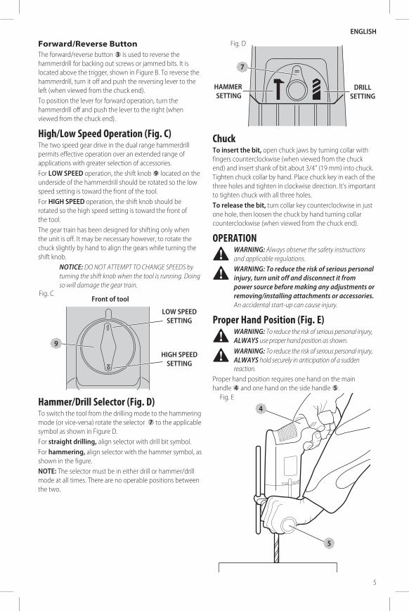
Forward/Reverse ButtonThe forward/reverse button 3 is used to reverse the hammerdrill for backing out screws or jammed bits. It is located above the trigger, shown in Figure B. To reverse the hammerdrill, turn it off and push the reversing lever to the left (when viewed from the chuck end).To position the lever for forward operation, turn the hammerdrill off and push the lever to the right (when viewed from the chuck end).
High/Low Speed Operation (Fig. C)The two speed gear drive in the dual range hammerdrill permits effective operation over an extended range of applications with greater selection of accessories.For lOW sPEED operation, the shift knob 9 located on the underside of the hammerdrill should be rotated so the low speed setting is toward the front of the tool.For high sPEED operation, the shift knob should be rotated so the high speed setting is toward the front of the tool.The gear train has been designed for shifting only when the unit is off. It may be necessary however, to rotate the chuck slightly by hand to align the gears while turning the shift knob.
NOTICE: DO NOT ATTEMPT TO CHANGE SPEEDS by turning the shift knob when the tool is running. Doing so will damage the gear train.
Front of tool
high sPEED sETTing
lOW sPEED sETTing
Fig. C
9
Hammer/Drill Selector (Fig. D)To switch the tool from the drilling mode to the hammering mode (or vice-versa) rotate the selector 7 to the applicable symbol as shown in Figure D.For straight drilling, align selector with drill bit symbol.For hammering, align selector with the hammer symbol, as shown in the figure.nOTE: The selector must be in either drill or hammer/drill mode at all times. There are no operable positions between the two.
Fig. D
7
hAMMER sETTing
DRill sETTing
ChuckTo insert the bit, open chuck jaws by turning collar with fingers counterclockwise (when viewed from the chuck end) and insert shank of bit about 3/4" (19 mm) into chuck. Tighten chuck collar by hand. Place chuck key in each of the three holes and tighten in clockwise direction. It’s important to tighten chuck with all three holes.To release the bit, turn collar key counterclockwise in just one hole, then loosen the chuck by hand turning collar counterclockwise (when viewed from the chuck end).
OPERATION
� WARNING: Always observe the safety instructions and applicable regulations.
� WARNING: To reduce the risk of serious personal injury, turn unit off and disconnect it from power source before making any adjustments or removing/installing attachments or accessories. An accidental start-up can cause injury.
Proper Hand Position (Fig. E)
� WARNING: To reduce the risk of serious personal injury, ALWAYS use proper hand position as shown.
� WARNING: To reduce the risk of serious personal injury, ALWAYS hold securely in anticipation of a sudden reaction.
Proper hand position requires one hand on the main handle 4 and one hand on the side handle 5 .
Fig. E
5
4

English
6
Drilling
� WARNING: To reduce the risk of personal injury, ALWAYS ensure workpiece is anchored or clamped firmly. If drilling thin material, use a wood “back-up” block to prevent damage to the material.
1. Use sharp drill bits only. For WOOD, use twist drill bits, spade bits, power auger bits, or hole saws. For METAL, use steel twist drill bits or hole saws. For MASONRY, such as brick, cement, cinder block, etc., use carbide-tipped bits rated for percussion drilling.
2. Always apply pressure in a straight line with the bit. Use enough pressure to keep drill biting, but do not push hard enough to stall the motor or deflect the bit.
3. Hold tool firmly with both hands to control the twisting action of the drill.
4. iF DRill sTAlls, it is usually because it is being overloaded or improperly used. RElEAsE TRiggER iMMEDiATElY, remove drill bit from work, and determine cause of stalling. DO nOT CliCK TRiggER On AnD OFF in An ATTEMPT TO sTART A sTAllED DRill — This CAn DAMAgE ThE DRill.
5. To minimize stalling or breaking through the material, reduce pressure on drill and ease the bit through the last fractional part of the hole.
6. Keep the motor running when pulling the bit back out of a drilled hole. This will help prevent jamming.
7. With variable speed drills there is no need to center punch the point to be drilled. Use a slow speed to start the hole and accelerate by squeezing the trigger harder when the hole is deep enough to drill without the bit skipping out.
Drilling in MetalUSE ONLY in the low-speed gear range. Start drilling with slow speed and increase to full power while applying firm pressure on the tool. A smooth even flow of metal chips indicates the proper drilling rate. Use a cutting lubricant when drilling metals. The exceptions are cast iron and brass which should be drilled dry.nOTE: Large [5/16" (8 mm) to 1/2" (13 mm)] holes in steel can be made easier if a pilot hole [5/32" (4 mm) to 3/16" (5 mm)] is drilled first.
Drilling in WoodUSE ONLY in the low-speed gear range. Start drilling with slow speed and increase to full power while applying firm pressure on the tool. Holes in wood can be made with the same twist drills used for metal. These bits may overheat unless pulled out frequently to clear chips from the flutes. Work that is apt to splinter should be backed up with a block of wood.
Drilling in MasonryWhen drilling in masonry, use carbide tipped bits rated for percussion drilling and be certain that the bit is sharp. For holes up to 3/8" (10 mm) diameter use the high-speed gear range. For holes larger than 3/8" (10 mm), use the the low-speed gear range. Ensure that the hammer mode is selected. Use a constant and firm force on the tool to drill most effectively. A smooth, even flow of dust indicates the proper drilling rate.
Depth Rod (Fig. A)To adjust the depth rod 8 , loosen the handle and move rod so that the distance between the end of the rod and the end of the bit equals the desired drilling depth. When drilling with depth rod, stop when end of rod reaches surface of material.
MAINTENANCE
� WARNING: To reduce the risk of serious personal injury, turn unit off and disconnect it from power source before making any adjustments or removing/installing attachments or accessories. An accidental start-up can cause injury.
Your DeWALT power tool has been designed to operate over a long period of time with a minimum of maintenance. Continuous satisfactory operation depends upon proper tool care and regular cleaning.
LubricationYour power tool requires no additional lubrication.
Cleaning
� WARNING: Blow dirt and dust out of all air vents with clean, dry air at least once a week. To minimize the risk of eye injury, always wear approved eye protection when performing this.
� WARNING: Never use solvents or other harsh chemicals for cleaning the non-metallic parts of the tool. These chemicals may weaken the plastic materials used in these parts. Use a cloth dampened only with water and mild soap. Never let any liquid get inside the tool; never immerse any part of the tool into a liquid.
Accessories
� WARNING: Since accessories, other than those offered by DeWALT, have not been tested with this product, use of such accessories with this tool could be hazardous. To reduce the risk of injury, only DeWALT recommended accessories should be used with this product.
Recommended accessories for use with your tool are available at extra cost from your local dealer or authorized service center.
English
7
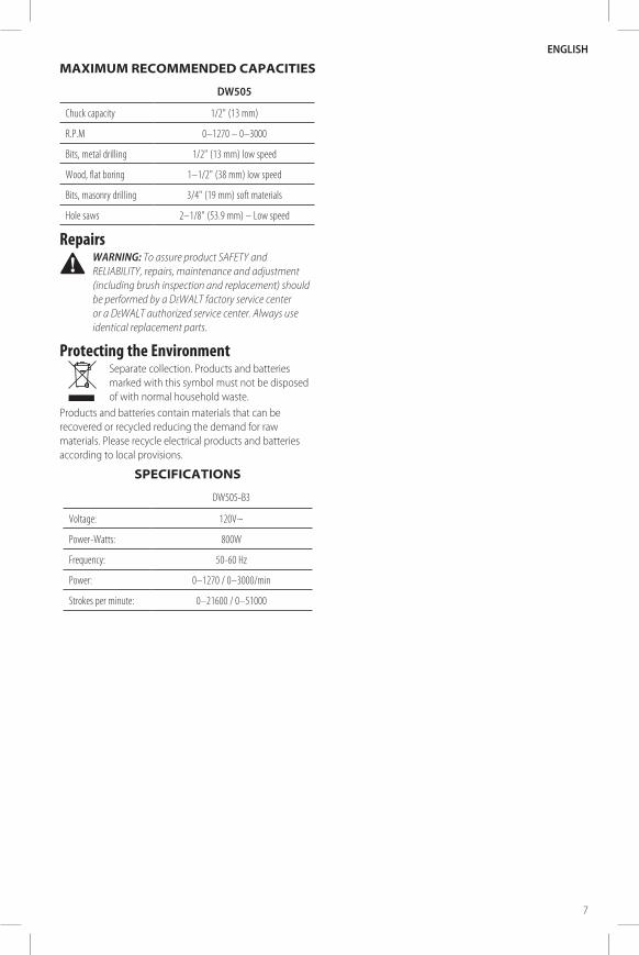
MAXIMUM RECOMMENDED CAPACITIES
DW505
Chuck capacity 1/2" (13 mm)
R.P.M 0–1270 – 0–3000
Bits, metal drilling 1/2" (13 mm) low speed
Wood, flat boring 1–1/2" (38 mm) low speed
Bits, masonry drilling 3/4" (19 mm) soft materials
Hole saws 2–1/8" (53.9 mm) – Low speed
Repairs
� WARNING: To assure product SAFETY and RELIABILITY, repairs, maintenance and adjustment (including brush inspection and replacement) should be performed by a DeWALT factory service center or a DeWALT authorized service center. Always use identical replacement parts.
Protecting the Environment Separate collection. Products and batteries marked with this symbol must not be disposed of with normal household waste.
Products and batteries contain materials that can be recovered or recycled reducing the demand for raw materials. Please recycle electrical products and batteries according to local provisions.
SPECIFICATIONS
DW505-B3
Voltage: 120V~
Power-Watts: 800W
Frequency: 50-60 Hz
Power: 0–1270 / 0–3000/min
Strokes per minute: 0–21600 / 0–51000


DeWALT Industrial Tool Co., 701 East Joppa Road, Towson, MD 21286 (Mar17) Part No. N482746 DW505 Copyright © 2003, 2006, 2011, 2017 DeWALT
The following are trademarks for one or more DeWALT power tools: the yellow and black color scheme, the “D” shaped air intake grill, the array of pyramids on the handgrip, the kit box configuration, and the array of lozenge-shaped humps on the surface of the tool.
Made in Brazil
Solamente para Propósitos de Argentina:Importa y Distribuye: Black & Decker Argentina S.A.
Pacheco Trade CenterColectora Este de Ruta Panamericana
Km. 32.0 El Talar de PachecoPartido de Tigre
Buenos Aires (B1618FBQ)República de Argentina
CUIT: 33-65861596-9Tel. (011) 4726-4400
Solamente para propósito de México:Importado por: Black & Decker S.A. de C.V.
Avenida Antonio Dovali Jaime, # 70 Torre B Piso 9Colonia Santa Fé
Delegación Alvaro ObregónMéxico D. F.: 01210
Tel. (52) 555-326-7100R.F.C.: BDE810626-1W7
Manufactured by/Fabricado por:Black & Decker do Brasil Ltda.
Rod. BR 050, s/n° - Km 167Dist. Industrial II
Uberaba – MG – Cep: 38064-750CNPJ: 53.296.273/0001-91
Insc. Est.: 701.948.711.00-98S.A.C.: 0800-703-4644
MAQUINAS Y HERRAMIENTAS BLACK & DECKER CHILE S.A.Avda. Eduardo Frei M. #6001 Edificio 67
Conchali-SantiagoChile
TEL: 56-2-26871706
IMPORTADO POR:BLACK & DECKER DEL PERÚ S.A.
Av. Circunvalación del Club Golf Los IncasN° 152 - 154, Lote 4, Oficinas 601 – 602
Urb. Club Golf Los Incas – Santiago de SurcoLima – Perú
TEL: (511) 614-4242RUC: 20266596805