115 - DDM JJ - EnviroTREC
43
Additive Manufacturing Aerospace – Defence
Transcript of 115 - DDM JJ - EnviroTREC

Additive ManufacturingAerospace – Defence

Empowering Innovation
• Founded in 1993
• Full Line Stratasys Partner for Canada
• Strong Design / Manufacturing background
• Service Commercial and Academic Markets
• Business based exclusively on Stratasys Products
Celebrating 20 Years
Who we are

• Stratasys Ltd. (SSYS) Nasdaq• #1 3D Printer Manufacturer in the world.
• Both in Revenue and Unit Sales
• 350M + Revenue
• Over 1200 employees
Who we are
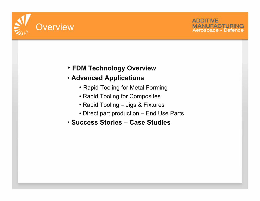
• FDM Technology Overview• Advanced Applications
• Rapid Tooling for Metal Forming
• Rapid Tooling for Composites
• Rapid Tooling – Jigs & Fixtures
• Direct part production – End Use Parts
• Success Stories – Case Studies
Overview

Finished PartPre-Process Manufacture1 32
FDM Process

Fused Deposition Modeling : FDM• Dual extrusion head technology• Deposit liquefied build and support• Precise Additive Fabrication• Advanced materials• Advanced mechanical properties• Safe, Simple, Clean process
FDM Process

• Envelope size• Materials• Accuracy• Throughput• Resolution
• Customization• Repeatability• Flexibility• Complex Part Fabrication
Differentiators Enablers
IDEA Series DESIGN SeriesPRODUCTION
Series
Stratasys Portfolio

Material Options
ABS-M30
ABS-M30i
ABS-ESD7
PC-ABS
PC (Polycarbonate)
PC-ISO Class 6 : Pharmaceutical
Ultem 9085 *
Polyphenylsulfone PPSF
Support Material
*Ultem 9085 is a trademark of SABIC Innovative Plastics IP BV.
FDM Materials
Engineering Grade Thermoplastics

FDM Material Properties
ULTEM 9085 Aerospace & Defence Grade
• SABIC Engineered• Certificate of Conformance available• High tensile and compressive strength• High operating temperature• Passes FAR 25.853
*Ultem 9085 is a trademark of SABIC Innovative Plastics IP BV.
FDM Materials

Aerospace Grade Thermoplastic
Passes FAR 25.853� Vertical burn test� FST zero rating � UL94 V0
Radiant Heat OSU 55/55 PASS
FDM MaterialsUltem 9085
Off Gassing ASTM E595
PASS
Total Mass Loss ( TML)
0.41 % 1.00 %
Collected Volatile Condensate Material (CVCM)
< 0.01%
0.10 %
Water Vapour Recovery Report (WVR)
0.37 Report
Result Limit

Established / Traditional
(Design)
Direct Digital Manufacturing
(Manufacturing)
Additive Manufacturing
Primary Applications
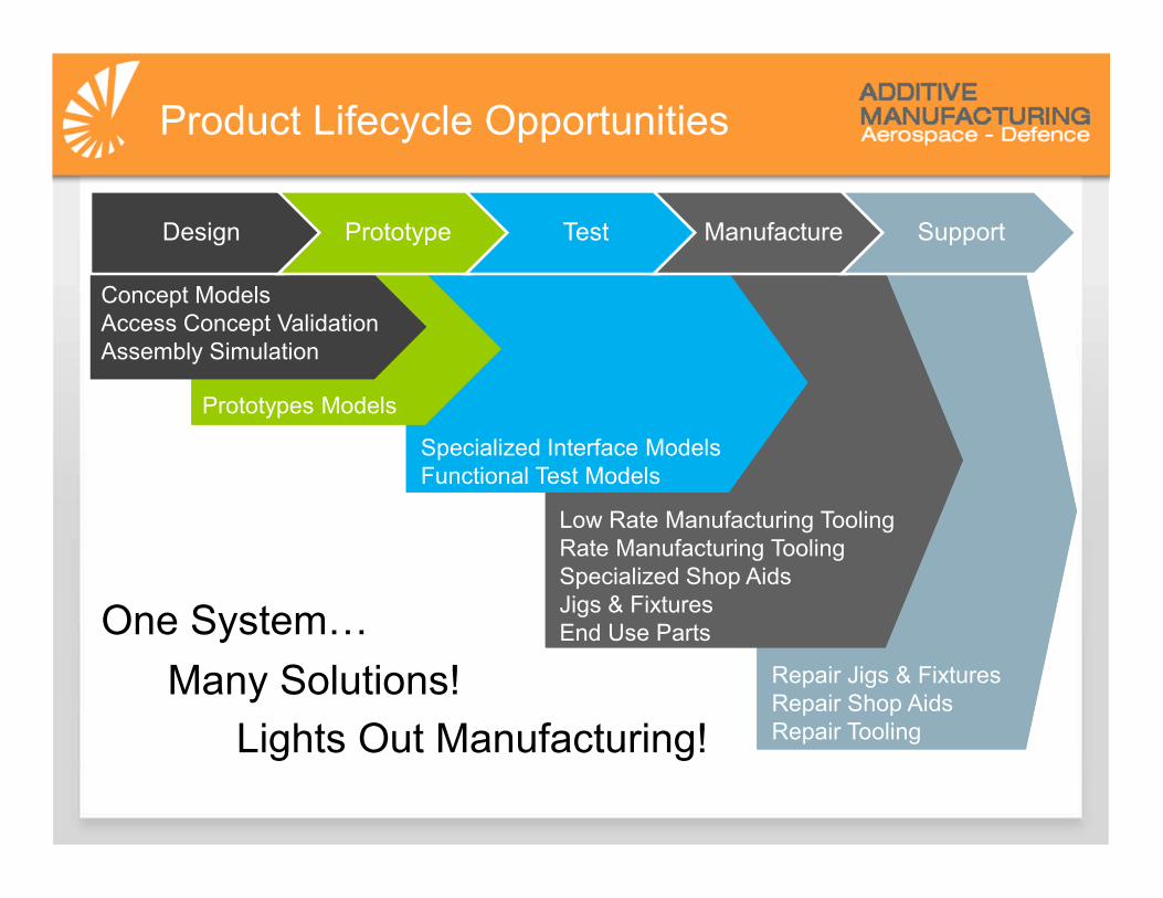
Design Prototype Test Manufacture Support
Concept ModelsAccess Concept ValidationAssembly Simulation
Prototypes Models
Specialized Interface ModelsFunctional Test Models
Low Rate Manufacturing ToolingRate Manufacturing ToolingSpecialized Shop AidsJigs & FixturesEnd Use Parts
Repair Jigs & FixturesRepair Shop AidsRepair Tooling
Product Lifecycle Opportunities
Many Solutions!
One SystemJ
Lights Out Manufacturing!

The Sweet Spot
Conventional Mfg.
Additive Mfg.
Quantity
Com
ple
xity
Sweet SpotHigh Complexity, Low Quantity• Specialty End Use Parts• Rapid Tooling• Low Volume Production

Advanced Applications

Metal FormingDemonstrated Application
Demonstrated Applications• Hydro Forming
• Rubber Pad Forming
Demonstrated Tooling• Female, Blow Down Tools
• Male Tools
• Punch Tools
• Pressure Intensifiers
• Matched Male & Female Tools
• Back Filled Tools
Demonstrated Conditions:• Range of alloys and thickness tested
• Demonstrated forming pressures up to 10KSI
• Variety of tools >100 cycles, some > 500 cycles
• Large jointed tools have been tested
Hydroform Rubber Pad
Pressure IntensifiersPunch
Blow Down Blow Down

Metal FormingDemonstrated Application
Large Tools• 2.3m Long Hydro Form Tool
• PC Material
• Methods to join parts proven
100+ Cycles
100+ Cycles
Optimized Tool• Match FDM material to forming pressure
• ABS max 20.7 MPa• PC max 55.2 MPa• ULTEM max 68.9 MPa
• Rubber Pad Tool optimized for cost and build time~ $200. in material~ 8 hour build time
Original Tool
100+ Cycles

Metal FormingDemonstrated Application : Coordinated Tool Family
Example
• MRO application
• Corrosion in frame needs repair
Solution
• Damage area is reverse engineered
• CAD model of repair is created
• Tool family built “lights out” with FDM
• Repair part fabricated with Hydroform tool
• Part trimmed & piloted at bench level
Benefits
• Entire repair is digitally coordinated
• Lights out tool fabrication
• Minimize time on aircraft
Frame needing repair
Tool Design
Hydroform
Tool
Trim & Drill
Tool
Installed
Part

“I can program an FDM part in 10 minutes while typical CNC
program takes four hours to write”
-Jacob Allenbaugh, Manufacturing Engineer, Piper Aircraft
Piper Reduces the Cost and Leadtime ofHydroforming Tool to Build a personal Jet
Metal FormingCase Study

• Program FDM part 10 min vs. 4 hrs CNC• No operator attendance• Less material waste
• Producing hundreds of aluminum structural components• Inner frame components, gussets, brackets, skins etc.
• FDM as the manufacturing process• PC Material 3000 to 6000 psi• Ultem 9085 for up to 10,000 psi
• Hydroform Tooling• Produce route , drill and trim fixtures with FDM
Aluminum Window Pan on top of FDM ToolAluminum Window Pan (left) FDM Tool
Metal FormingCase Study

FDM Composite Applications
Patterns
Ma
ste
rs
Pre
La
yup
Co
nso
lida
tio
n T
oo
ls
Lay Up / Cure Tools
Lo
w T
em
p
Hig
h T
em
p
Bo
nd
ing
Fix
ture
s
Inte
nsifie
rs
Ca
ulP
late
s
Consumable Cores
So
lub
le C
ore
s
Ne
t S
ha
pe
d C
ore
s
Inte
gra
ted
In
terf
ace
s
Digitally Coordinated Tool Families
Tri
m T
oo
l
Dri
ll To
ol
Ch
eck F
ixtu
re
Composite Applications

FDM Tool Material Selection
• Maximum tool use temperature (usually the same as resin cure temperature) determines the material choice.
CTE Compensation
• Part size & accuracy requirements determine whether CTE compensation is required.
Tool Bagging Method
• Determines developed loads on tool & tool surface finish requirements.
Tool Build Orientation
• Build orientation affects surface roughness and tool strength.
Tool Finishing
• Tool finishing method is dependent on desired part surface finish.
Composite ApplicationsFDM Tool Design Considerations

AMB 180˚F 250˚F 350˚F
ServiceTemp
•Low Temp Tools•Low Temp Consumable Cores•Master Patterns
ABS
•SR30 Soluble CoresSR30/SR100
•Low Temp Cure Tools & Consumable Cores•Master Patterns•Trim & Drill Tools
PC
•Med Temp Cure Tools & Consumable Cores•High Strength Trim & Drill ToolsULTEM
•High Temp Tools & Consumable CoresPPSF
•High Temp CTE Matched ToolsABS Master &
Tooling Composites
•High Temp CTE Matched Tools•High Temp CTE Matched Soluble Cores
ABS Master & Nevada Composites +300˚C (600˚F)
200˚C (400˚F) Max
AMB 80˚C 120˚C 175˚C
• SR100 Soluble Cores
• Within limits
FDMMaterials
Composite ApplicationsMaterial Compatibility

Composite Lay-Up ToolingDemonstrated Application
Demonstrated Lay-Ups
• Fibers: Carbon, Glass, Kevlar
• Resin Systems: Epoxy & Polyester
Demonstrated Tools
• Patterns – Low Temp Cure Tooling Composite
• Lay Up Tools < 350˚F (177˚C ) cure
• Pre-lay up/ply consolidation tool
• Pressure intensifiers / caul plates
Notes
• Surfacing methods available
• Release agents tested
• CTE compensation must be considered
• FDM material CTE information available.

Composite Lay-Up ToolingThin Skin Application
Design• Ultem Material
• 6 mm thick
• Build Time: 5 hrs
• Tool surfaced with epoxy
• Vibratory polish (hands off) 1 hour
Use• Release surface
• Lay up part
• Envelope bagging balances forces
• Cured @ 250 F, @ 80 psi
• Geometry Sensitive

Composite Lay-Up ToolingThin Skin Application
Tool
• Thickness 8mm (0.31”)
• Material PPSF
Lay Up
• Aramid fiber, 108g.m2
• 180 c epoxy resin
Results
• Final tolerance ±0.25 (0.010”) on 350mm (12”)
• No spring back effect on “C” shape
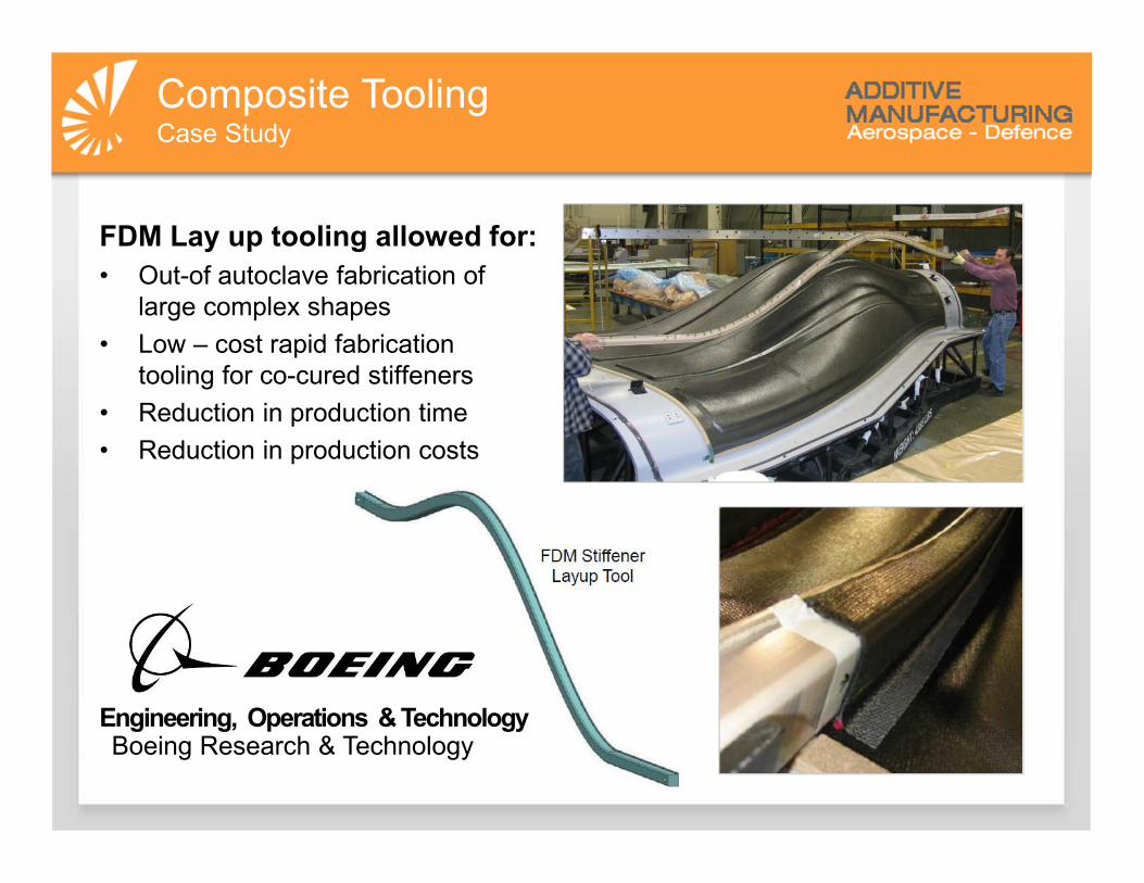
Composite ToolingCase Study
FDM Lay up tooling allowed for:
• Out-of autoclave fabrication of large complex shapes
• Low – cost rapid fabrication tooling for co-cured stiffeners
• Reduction in production time
• Reduction in production costs
Engineering, Operations & TechnologyBoeing Research & Technology

Composite Soluble CoresDemonstrated Application
Complex shapes• Wide variety of shapes and sizes in test
High strength• Not brittle• Handles off axis winding loads
Wash Out• Hot water & detergent• Compatible with epoxy resins• Not recommended for polyester resins
Benefits• Reduces costs, cycle times, risk
• Eliminates traditional mandrel cast tooling & labor & cycle time
• Eliminates scrap rates related to traditional mandrel removal
• Provides flexibility for early design iterations

Composite Break Out CoresDemonstrated Application
Ultem S1 Core
Cured Part
Ultem S1 Core• Compromised with acetone• Becomes brittle• Broken into pieces for removal
1 2
3 4

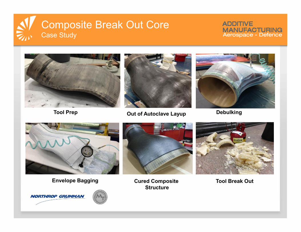
Composite Break Out CoreCase Study

Composite Break Out CoreCase Study
Application• Inlet duct size =0.6 m x 0.6m x 0.9m (2’x2’x3’)• Trapped geometry
Solution• 180 degree Celsius OoA composite system• 2 hr 130 C (266 F) initial cure• 2 hr free standing 180 C (356 F) post cure• Ultem S1 break out core
Results• Tool build time < 8 days• Reduced tool lead time to < 14 days• Tool maintained less than +/- 1 mm (0.040”) accuracy
Project worked with NGC under Call 6 Program
Composite Break Out CoreCase Study
Tool Prep Out of Autoclave Layup Debulking
Envelope Bagging Cured Composite Structure
Tool Break Out

Example
• Aircraft access door
Coordinated Tools & Parts
• Lay up mold defined by solid model
• Net shaped core defined by same model
• Trim & drill tool mastered to same solid model
La
y U
p M
old
Ne
t S
ha
pe
d C
ore
Tri
m T
oo
l
Fin
ish
ed
Pa
rtCoordinated Tool FamilyDemonstrated Application

Types
• Scribe Tool
• Edge of tool is net
• Scribe is used to transfer EOP to
part
• Off Set Tool
• Tool edge is inset
• Provides guide surface for cutting tool
• Prevents removal of too much material
When to use FDM
• Complex shapes
• Ergonomic light weight
• More stable than fiberglass in high humidity environments
Trim ToolDemonstrated Application
~18”R

Drill ToolDemonstrated Application
Types
• Direct Built
• Shape and hole pattern are controlled by FDM build
• Precision
• Shape built on FDM
• Hole pattern drilled by CNC
• Transfer
• Build desired shape with FDM
• Bushings potted while pinned to master
When to use
• Complex shapes
• Multi axis hole patterns
• Ergonomic light weight
• More stable than fibreglass in humid environments
Coordinated Tool FamilyWith Drill Tool

ThermoformingDemonstrated Application
Demonstration
• FDM Tool Material – ULTEM
• Formed 0.25” Kydex material
• Tool built with internal structures for
• Combination of internal porosity and stiffeners
• Heavier forming pressures
• Higher temperatures
• Higher material shrinkage forces
Results
• 100% drawn down achieved
• Tough corners formed well
• Shape & complexity is a strength of FDM

• Assembly Tools
• Jigs & Fixtures
• Surrogate Parts
Benefits
• Custom interfaces for complex surfaces
• Minimize part handling damage
• Optimized for access without increased costs
• Light weight ergonomic
Assembly AidsDemonstrated Application

Enables:
• Reduced dependency on external suppliers
• Overnight fulfillment of new tooling requirements
• Lights out fabrication
• Digitally mastered coordinated tooling
Resulting in:
• Reduced cycle times up to 85%
• Cost savings up to 80%
• Improved quality
FDM ToolingBenefits Summary

Direct benefits:
• Lower cost
• Shorter lead time
Indirect benefits:
• Design freedom
• Change freedom
• Mass customization
• Weight reductions
• Part consolidation
• Supports lean initiatives
• True JIT (just-in-time) manufacturing
• Reduced warehouse space/inventory cost
FDM End Use Parts

End Use PartsCase Study
FDM End use parts allowed for:
• Flexibility when designing complex parts• Manufacture of less expensive part• Weight saving solutions• Production of parts that meet FAA
regulatory requirements to be installed on aircraft
• Low volume production• No tooling required

Best fit when:
• Relatively low volumes– Short run production– Bridge to tooling
• High part complexity– Eliminate expensive tooling– Reduce long lead times
• Part acceptable
– Aesthetics not critical– Finishing processes feasible– Physical properties acceptable
End Use Parts
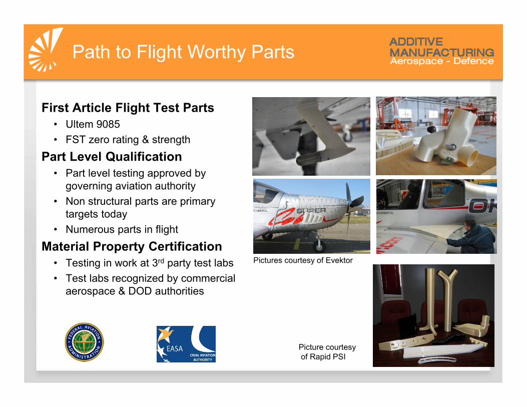
First Article Flight Test Parts
• Ultem 9085
• FST zero rating & strength
Part Level Qualification
• Part level testing approved by governing aviation authority
• Non structural parts are primary targets today
• Numerous parts in flight
Material Property Certification
• Testing in work at 3rd party test labs
• Test labs recognized by commercial aerospace & DOD authorities
Pictures courtesy of Evektor
Picture courtesyof Rapid PSI
Path to Flight Worthy Parts
What inspires you is your business
How you make it real is ours.
THANK YOU