10 SERIES PUMPS - Absolute Water Pumps 10 SERIES PUMPS INTRODUCTION PAGE I -- 1 INTRODUCTION Thank...
24
PUBLICATION NUMBER MR--04959 January 19, 1999 Use With: OM-- 04760 THE GORMAN-RUPP COMPANY D MANSFIELD, OHIO GORMAN-RUPP OF CANADA LIMITED D ST. THOMAS, ONTARIO, CANADA Printed in U.S.A. ECopyright by the Gorman-Rupp Company 10 SERIES PUMPS 13D, 14A, 14C, 14D And 16D Closed Coupled Electric Motor Or Engine Driven Pumps with Self Lubricated Seal or Grease Seal
Transcript of 10 SERIES PUMPS - Absolute Water Pumps 10 SERIES PUMPS INTRODUCTION PAGE I -- 1 INTRODUCTION Thank...

PUBLICATION NUMBER MR--04959January 19, 1999
Use With: OM--04760
THE GORMAN-RUPP COMPANY D MANSFIELD, OHIOGORMAN-RUPP OF CANADA LIMITED D ST. THOMAS, ONTARIO, CANADA Printed in U.S.A.
ECopyright by the Gorman-Rupp Company
10 SERIES PUMPS13D, 14A, 14C, 14D And 16D Closed Coupled
Electric Motor Or Engine Driven Pumps
with Self Lubricated Seal or Grease Seal
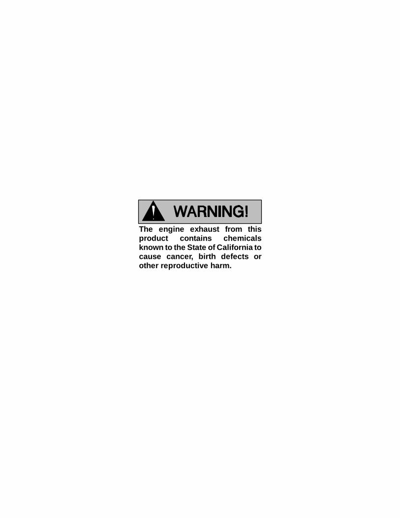
The engine exhaust from thisproduct contains chemicalsknown to the State of California tocause cancer, birth defects orother reproductive harm.

MR--04959 10 SERIES PUMPS
PAGE I -- 1INTRODUCTION
INTRODUCTION
Thank You for purchasing a Gorman-Rupp 10Series Pump. Read this manual carefully to learnhow to safely maintain and service your pump. Fail-ure to do so could result in personal injury or dam-age to the pump.
A set of three manuals accompanies your pump.The Installation/Operation Manual contains essen-tial information on installing and operating thepump. The Parts List Manual provides a perform-ance curve, a pump model cross-section drawing,and parts list for your pump.
This Maintenance and Repair Manual providestroubleshooting and maintenance instructions re-quired to properly diagnose operational problems,and to service the pump components.
As described on the following page, this manualwill alert personnel to known procedures which re-quire special attention, to those which could dam-age equipment, and to those which could be dan-gerous to personnel. However, this manual cannotpossibly anticipate and provide detailed precau-tions for every situation that might occur during
maintenance of the pump. Therefore, it is the re-sponsibility of the owner/maintenance personnelto ensure that only safe, established maintenanceprocedures are used, and that any procedures notaddressed in this manual are performed only afterestablishing that neither personal safety nor pumpintegrity are compromised by such practices.Pumps and related equipment must be installedand operated according to all national, local and in-dustry standards.
If there are any questions regarding the pumpwhich are not covered in this manual or in other lit-erature accompanying the unit, please contactyour Gorman-Rupp distributor or the Gorman-Rupp Company:
The Gorman-Rupp CompanyP.O. Box 1217
Mansfield, Ohio 44901--1217or:
Gorman-Rupp of Canada Limited70 Burwell Road
St. Thomas, Ontario N5P 3R7
CONTENTS
SAFETY -- SECTION ATROUBLESHOOTING -- SECTION B
PREVENTIVE MAINTENANCE PAGE B --- 3. . . . . . . . . . . . . . . . . . . . . . . . . . . . . . . . . . . . . . . . . . . . . . . . . .PUMP MAINTENANCE AND REPAIR -- SECTION C
GENERAL INFORMATION PAGE C --- 1. . . . . . . . . . . . . . . . . . . . . . . . . . . . . . . . . . . . . . . . . . . . . . . . . . . . .Lifting PAGE C --- 1. . . . . . . . . . . . . . . . . . . . . . . . . . . . . . . . . . . . . . . . . . . . . . . . . . . . . . . . . . . . . . . . . . . .
PARTS IDENTIFICATION LIST:Pump Assembly w/Self Lubricated Seal PAGE C --- 3. . . . . . . . . . . . . . . . . . . . . . . . . . . . . . . . . . . . . .Pump Assembly w/Grease Seal PAGE C --- 5. . . . . . . . . . . . . . . . . . . . . . . . . . . . . . . . . . . . . . . . . . . . .
PUMP AND SEAL DISASSEMBLY AND REASSEMBLY PAGE C --- 6. . . . . . . . . . . . . . . . . . . . . . . . . . . .Impeller Clearances PAGE C --- 11. . . . . . . . . . . . . . . . . . . . . . . . . . . . . . . . . . . . . . . . . . . . . . . . . . . . . .
LUBRICATION PAGE C --- 12. . . . . . . . . . . . . . . . . . . . . . . . . . . . . . . . . . . . . . . . . . . . . . . . . . . . . . . . . . . . . . .Self Lubricated Seal Assembly PAGE C --- 12. . . . . . . . . . . . . . . . . . . . . . . . . . . . . . . . . . . . . . . . . . . . .Grease Seal Assembly PAGE C --- 12. . . . . . . . . . . . . . . . . . . . . . . . . . . . . . . . . . . . . . . . . . . . . . . . . . . .Power Source PAGE C --- 13. . . . . . . . . . . . . . . . . . . . . . . . . . . . . . . . . . . . . . . . . . . . . . . . . . . . . . . . . . .
MR--0495910 SERIES PUMPS
PAGE I -- 2 INTRODUCTION
RECORDING MODEL ANDSERIAL NUMBERS
Please record the pump model, serial number, volt-age, and phase in the spaces provided below. YourGorman-Rupp distributor needs this informationwhen you require parts or service.
Pump Model:
Serial Number:
Motor:
Voltage:
Phase:
Engine:
Model:
Serial Number:
WARRANTY INFORMATION
The warranty provided with your pump is part ofGorman-Rupp’s support program for customerswho operate and maintain their equipment as de-scribed in this and the other accompanying litera-ture. Please note that should the equipment beabused or modified to change its performance be-yond the original factory specifications, the war-ranty will become void and any claim will be de-nied.
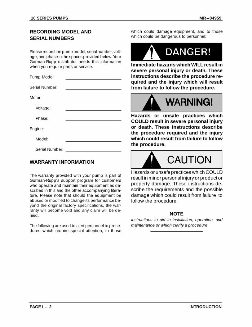
The following are used to alert personnel to proce-dures which require special attention, to those
which could damage equipment, and to thosewhich could be dangerous to personnel:
Immediate hazards which WILL result insevere personal injury or death. Theseinstructions describe the procedure re-quired and the injury which will resultfrom failure to follow the procedure.
Hazards or unsafe practices whichCOULD result in severe personal injuryor death. These instructions describethe procedure required and the injurywhich could result from failure to followthe procedure.
Hazards or unsafe practices which COULDresult in minor personal injury or product orproperty damage. These instructions de-scribe the requirements and the possibledamage which could result from failure tofollow the procedure.
NOTEInstructions to aid in installation, operation, andmaintenance or which clarify a procedure.

10 SERIES PUMPS MR--04959
PAGE A -- 1SAFETY
SAFETY - SECTION A
This information applies to 10 Serieselectric motor or engine driven pumps.Refer to the manual accompanying thepower source before attempting to be-gin operation.
This manual will alert personnel toknown procedures which require spe-cial attention, to those which coulddamage equipment, and to those whichcould be dangerous to personnel. How-ever, this manual cannot possibly antici-pate and provide detailed instructionsand precautions for every situation thatmight occur during maintenance of theunit. Therefore, it is the responsibility ofthe owner/maintenance personnel toensure that only safe, established main-tenance procedures are used, and thatany procedures not addressed in thismanual are performed only after estab-lishing that neither personal safety norpump integrity are compromised bysuch practices.
This manual contains essential informa-tion on troubleshooting and maintain-ing the pump. In addition to this manual,see the separate literature coveringinstallation and operation, pump parts,and any optional equipment shippedwith the pump.
Before attempting to open or service thepump:
1. Familiarize yourself with this man-ual.
2. Disconnect or shut down the pow-er source and take the necessaryprecautions to ensure that thepump will remain inoperative.
3. Allow the pump to completely coolif overheated.
4. Check the temperature beforeopening any covers, plates, orplugs.
5. Close the suction and dischargevalves.
6. Vent the pump slowly and cau-tiously.
7. Drain the pump.
Do not attempt to pump any liquids thepump has not been designed for, andwhich may damage the pump or endan-ger personnel as a result of pump fail-ure. Consult the factory to determinecompatibility between the pump and liq-uid.
Use lifting and moving equipment ingood repair and with adequate capacityto prevent injuries to personnel or dam-age to equipment. Suction and dis-charge hoses and piping must be re-moved from the pump before lifting.
After the pump has been positioned,make certain that the pump and all pip-ing or hose connections are tight, prop-erly supported and secure before oper-ation.
Do not operate the pump against aclosed discharge valve for long periodsof time. If operated against a closed dis-charge valve, pump components will
10 SERIES PUMPSMR--04959
PAGE A -- 2 SAFETY
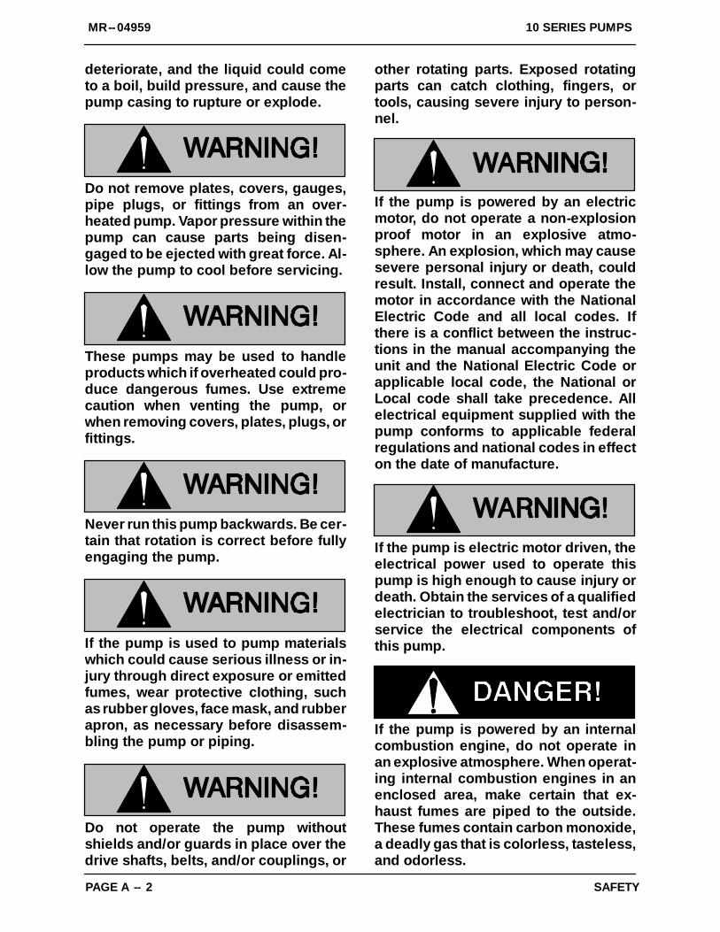
deteriorate, and the liquid could cometo a boil, build pressure, and cause thepump casing to rupture or explode.
Do not remove plates, covers, gauges,pipe plugs, or fittings from an over-heated pump. Vapor pressure within thepump can cause parts being disen-gaged to be ejected with great force. Al-low the pump to cool before servicing.
These pumps may be used to handleproducts which if overheated could pro-duce dangerous fumes. Use extremecaution when venting the pump, orwhen removing covers, plates, plugs, orfittings.
Never run this pump backwards. Be cer-tain that rotation is correct before fullyengaging the pump.
If the pump is used to pump materialswhich could cause serious illness or in-jury through direct exposure or emittedfumes, wear protective clothing, suchas rubber gloves, face mask, and rubberapron, as necessary before disassem-bling the pump or piping.
Do not operate the pump withoutshields and/or guards in place over thedrive shafts, belts, and/or couplings, or
other rotating parts. Exposed rotatingparts can catch clothing, fingers, ortools, causing severe injury to person-nel.
If the pump is powered by an electricmotor, do not operate a non-explosionproof motor in an explosive atmo-sphere. An explosion, which may causesevere personal injury or death, couldresult. Install, connect and operate themotor in accordance with the NationalElectric Code and all local codes. Ifthere is a conflict between the instruc-tions in the manual accompanying theunit and the National Electric Code orapplicable local code, the National orLocal code shall take precedence. Allelectrical equipment supplied with thepump conforms to applicable federalregulations and national codes in effecton the date of manufacture.
If the pump is electric motor driven, theelectrical power used to operate thispump is high enough to cause injury ordeath. Obtain the services of a qualifiedelectrician to troubleshoot, test and/orservice the electrical components ofthis pump.
If the pump is powered by an internalcombustion engine, do not operate inan explosive atmosphere. When operat-ing internal combustion engines in anenclosed area, make certain that ex-haust fumes are piped to the outside.These fumes contain carbon monoxide,a deadly gas that is colorless, tasteless,and odorless.

10 SERIES PUMPS MR--04959
PAGE A -- 3SAFETY
Fuel used by internal combustion en-gines presents an extreme explosionand fire hazard. Make certain that allfuel lines are securely connected andfree of leaks. Never refuel a hot or run-ning engine. Avoid overfilling the fueltank. Always use the correct type of fuel.
Never tamper with the engine governorto gain more power. The governor esta-blishes safe operating limits that shouldnot be exceeded. The maximum contin-uous operating speed for the pump isshown on the performance curve (seethe Parts List Manual).
Pumps and related equipment must be in-stalled and operated according to all na-tional, local and industry standards.
MR--0495910 SERIES PUMPS
TROUBLESHOOTING PAGE B -- 1
TROUBLESHOOTING --- SECTION B
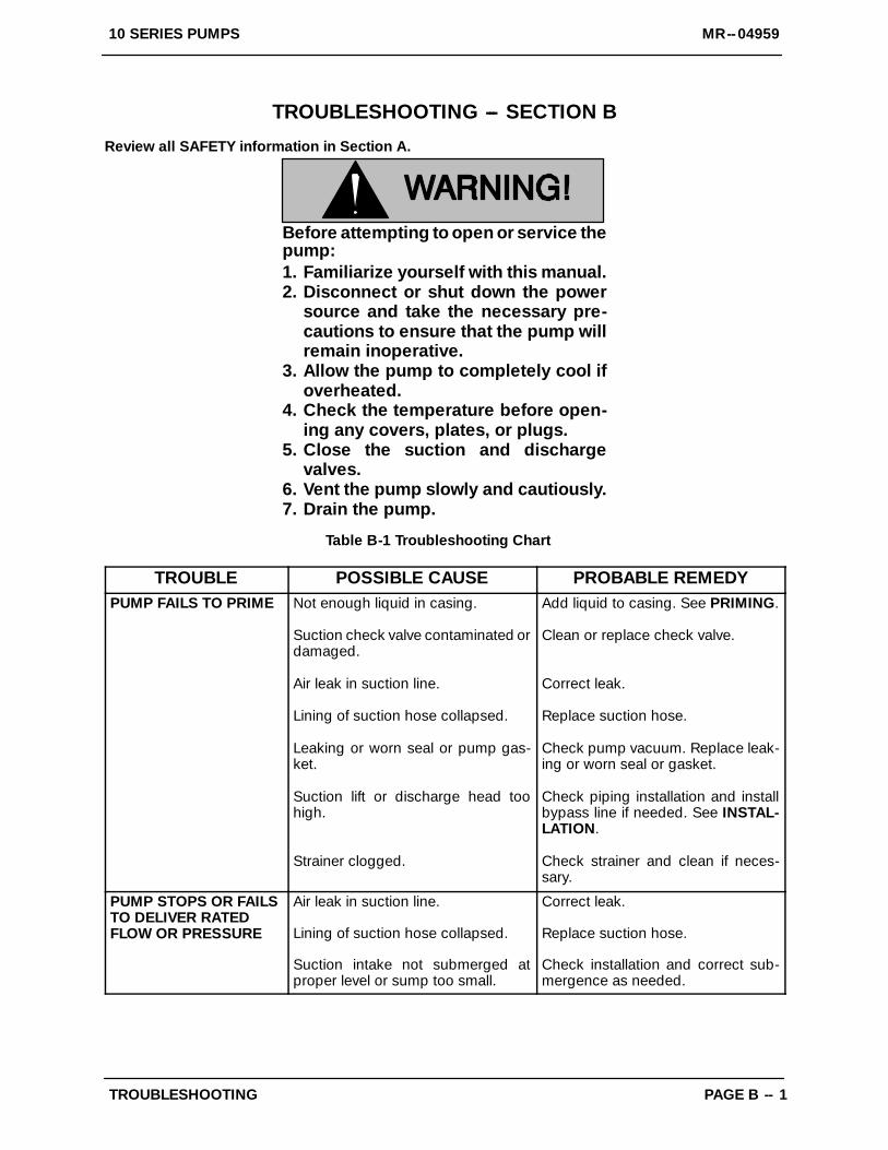
Review all SAFETY information in Section A.
Before attempting to open or service thepump:1. Familiarize yourself with this manual.2. Disconnect or shut down the power
source and take the necessary pre-cautions to ensure that the pump willremain inoperative.
3. Allow the pump to completely cool ifoverheated.
4. Check the temperature before open-ing any covers, plates, or plugs.
5. Close the suction and dischargevalves.
6. Vent the pump slowly and cautiously.7. Drain the pump.
Table B-1 Troubleshooting Chart
TROUBLE POSSIBLE CAUSE PROBABLE REMEDYPUMP FAILS TO PRIME Not enough liquid in casing.
Suction check valve contaminated ordamaged.
Air leak in suction line.
Lining of suction hose collapsed.
Leaking or worn seal or pump gas-ket.
Suction lift or discharge head toohigh.
Strainer clogged.
Add liquid to casing. See PRIMING.
Clean or replace check valve.
Correct leak.
Replace suction hose.
Check pump vacuum. Replace leak-ing or worn seal or gasket.
Check piping installation and installbypass line if needed. See INSTAL-LATION.
Check strainer and clean if neces-sary.
PUMP STOPS OR FAILSTO DELIVER RATEDFLOW OR PRESSURE
Air leak in suction line.
Lining of suction hose collapsed.
Suction intake not submerged atproper level or sump too small.
Correct leak.
Replace suction hose.
Check installation and correct sub-mergence as needed.
MR--04959 10 SERIES PUMPS
TROUBLESHOOTINGPAGE B -- 2
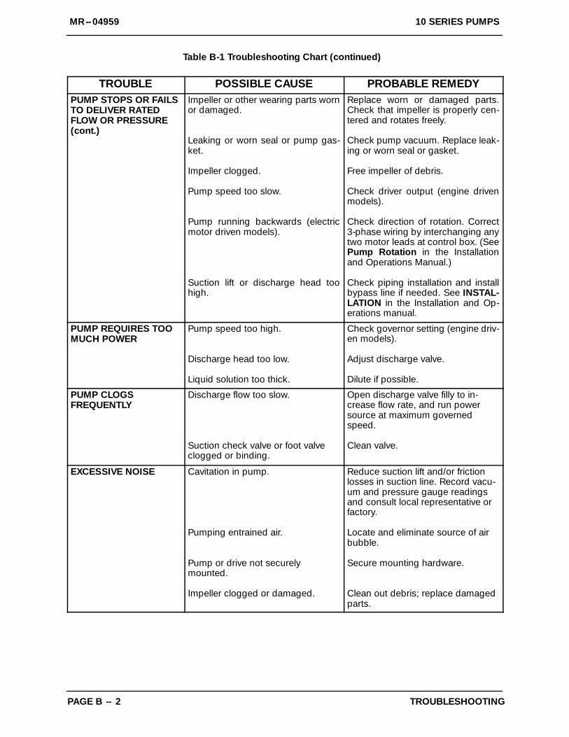
Table B-1 Troubleshooting Chart (continued)
TROUBLE POSSIBLE CAUSE PROBABLE REMEDYPUMP STOPS OR FAILSTO DELIVER RATEDFLOW OR PRESSURE(cont.)
Impeller or other wearing parts wornor damaged.
Leaking or worn seal or pump gas-ket.
Impeller clogged.
Pump speed too slow.
Pump running backwards (electricmotor driven models).
Suction lift or discharge head toohigh.
Replace worn or damaged parts.Check that impeller is properly cen-tered and rotates freely.
Check pump vacuum. Replace leak-ing or worn seal or gasket.
Free impeller of debris.
Check driver output (engine drivenmodels).
Check direction of rotation. Correct3-phase wiring by interchanging anytwo motor leads at control box. (SeePump Rotation in the Installationand Operations Manual.)
Check piping installation and installbypass line if needed. See INSTAL-LATION in the Installation and Op-erations manual.
PUMP REQUIRES TOOMUCH POWER
Pump speed too high.
Discharge head too low.
Liquid solution too thick.
Check governor setting (engine driv-en models).
Adjust discharge valve.
Dilute if possible.
PUMP CLOGSFREQUENTLY
Discharge flow too slow.
Suction check valve or foot valveclogged or binding.
Open discharge valve filly to in-crease flow rate, and run powersource at maximum governedspeed.
Clean valve.
EXCESSIVE NOISE Cavitation in pump.
Pumping entrained air.
Pump or drive not securelymounted.
Impeller clogged or damaged.
Reduce suction lift and/or frictionlosses in suction line. Record vacu-um and pressure gauge readingsand consult local representative orfactory.
Locate and eliminate source of airbubble.
Secure mounting hardware.
Clean out debris; replace damagedparts.
MR--0495910 SERIES PUMPS
TROUBLESHOOTING PAGE B -- 3
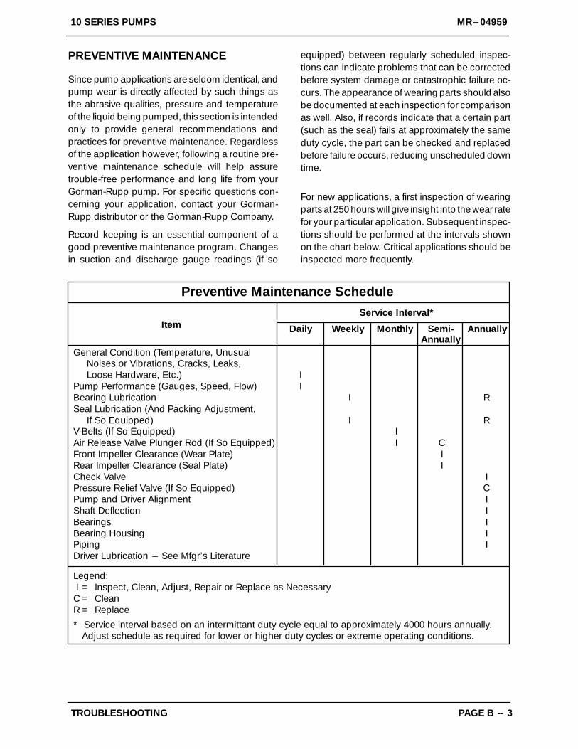
PREVENTIVE MAINTENANCE
Since pump applications are seldom identical, andpump wear is directly affected by such things asthe abrasive qualities, pressure and temperatureof the liquid being pumped, this section is intendedonly to provide general recommendations andpractices for preventive maintenance. Regardlessof the application however, following a routine pre-ventive maintenance schedule will help assuretrouble-free performance and long life from yourGorman-Rupp pump. For specific questions con-cerning your application, contact your Gorman-Rupp distributor or the Gorman-Rupp Company.
Record keeping is an essential component of agood preventive maintenance program. Changesin suction and discharge gauge readings (if so
equipped) between regularly scheduled inspec-tions can indicate problems that can be correctedbefore system damage or catastrophic failure oc-curs. The appearance of wearing parts should alsobe documented at each inspection for comparisonas well. Also, if records indicate that a certain part(such as the seal) fails at approximately the sameduty cycle, the part can be checked and replacedbefore failure occurs, reducing unscheduled downtime.
For new applications, a first inspection of wearingparts at 250 hours will give insight into the wear ratefor your particular application. Subsequent inspec-tions should be performed at the intervals shownon the chart below. Critical applications should beinspected more frequently.
General Condition (Temperature, UnusualNoises or Vibrations, Cracks, Leaks,Loose Hardware, Etc.) I
Pump Performance (Gauges, Speed, Flow) IBearing Lubrication I RSeal Lubrication (And Packing Adjustment,
If So Equipped) I RV-Belts (If So Equipped) IAir Release Valve Plunger Rod (If So Equipped) I CFront Impeller Clearance (Wear Plate) IRear Impeller Clearance (Seal Plate) ICheck Valve IPressure Relief Valve (If So Equipped) CPump and Driver Alignment IShaft Deflection IBearings IBearing Housing IPiping IDriver Lubrication --- See Mfgr’s Literature
Legend:I = Inspect, Clean, Adjust, Repair or Replace as Necessary
C = CleanR = Replace* Service interval based on an intermittant duty cycle equal to approximately 4000 hours annually.
Adjust schedule as required for lower or higher duty cycles or extreme operating conditions.
Preventive Maintenance Schedule
Item Daily Weekly Monthly Semi-Annually
Annually
Service Interval*
MR--04959 10 SERIES PUMPS
PAGE C -- 1MAINTENANCE AND REPAIR
PUMP MAINTENANCE AND REPAIR --- SECTION C
GENERAL INFORMATION
Review all SAFETY information in Section A.
Follow the instructions on all tags, label and de-cals attached to the pump.
Before attempting to install, operate, orservice this pump, familiarize yourselfwith this manual, and with all other liter-ature shipped with the pump. Unfamil-iarity with all aspects of operation ormaintenance could lead to destructionof equipment, injury or death to person-nel.
Use lifting and moving equipment ingood repair and with adequate capacityto prevent injuries to personnel or dam-age to equipment. If slings or chains areused to move the pump or components,make sure that the load is balanced;otherwise serious personal injury ordeath could result. Suction and dis-charge hoses and piping must be re-moved from the pump before lifting.
The maintenance and repair instructions in thismanual are keyed to the sectional views (FigureC---1 or C---2), and the corresponding parts identifi-cation list. Refer to the separate Parts List Manualfor replacement parts.
Select a suitable location, preferably indoors, toperform required maintenance.
This Maintenance and Repair Manual providestroubleshooting and maintenance instructions re-quired to properly diagnose operational problems,and to service the pump components. Mainte-nance instructions within this manual are limited tothe pump hydraulic, priming and drive compo-nents only.
Check TROUBLESHOOTING, Section B to deter-mine causes and remedies of pump problems.Disassemble the pump only as far as required.
As described in the SAFETY Section, this manualwill alert personnel to known procedures which re-quire special attention, to those which could dam-age equipment, and to those which could be dan-gerous to personnel. However, this manual cannotpossibly anticipate and provide detailed precau-tions for every situation that might occur duringmaintenance of the unit. Therefore, it is the respon-sibility of the owner/maintenance personnel to en-sure that only safe, established shop proceduresare used, and that any procedures not addressedin this manual are performed only after establish-ing that neither personal safety nor pump integrityare compromised by such practices.
Lifting
Use lifting equipment with a capacity of at leastfive times the weight of the pump, including theweight of any options or customer-installed acces-sories. Discharge hose or piping must be removedbefore attempting to lift the pump.
For the approximate weight of your pump, refer tothe pump specification data sheet or contact yourGorman-Rupp distributor or the Gorman-RuppCompany.

10 SERIES PUMPS MR--04959
MAINTENANCE AND REPAIRPAGE C -- 2
SECTION DRAWING
14D BACKCOVER DETAIL
14D FILLPLUG DETAIL
14D CHECKVALVE DETAIL
14C FILLCOVER DETAIL
Figure C---1. Typical 14C And 14D Pump End Assemblyw/Self Lubricated Mechanical Seal

ITEMNO. PART NAME
ITEMNO. PART NAME
MR--04959 10 SERIES PUMPS
PAGE C -- 3MAINTENANCE AND REPAIR
Typical 14C And 14D Pump End Assembly w/Self Lubricated Mechanical SealParts Identification List
Refer to the separate Parts List Manual for serviceable parts, part numbers and quantities.
1 PUMP CASING2 IMPELLER3 SEAL ASSEMBLY4 STREET ELBOW (IF REQUIRED)5 HEX HEAD CAPSCREW6 LOCKWASHER OR FLAT WASHER
(IF REQUIRED)7 DISCHARGE FLANGE8 DISCHARGE FLANGE GASKET9 NAME PLATE
10 DRIVE SCREW11 HEX HD CAPSCREW (IF REQUIRED)12 IMPELLER WASHER (IF REQUIRED)13 IMP SHAFT KEY (IF REQUIRED)14 SLINGER RING (IF REQUIRED)15 IMPELLER SHIM SET16 SPRING CNTR WASHER (IF REQ.)17 SHAFT SLEEVE18 STUD19 LOCKWASHER OR FLAT WASHER20 HEX NUT21 INTERMEDIATE22 STUD OR LOCKWASHER23 HEX NUT OR HEX HD CAPSCREW24 CASING GSKT SET OR O-RING25 WEAR PLATE ASSEMBLY26 CASING DRAIN PLUG27 LOCKWASHER28 HEX NUT29 CLAMP BAR (IF REQUIRED)30 CLAMP BAR SCREW (IF REQUIRED)31 MACHINE BOLT (IF REQUIRED)
32 BACK COVER PLATE ASSEMBLY33 ---PIPE PLUG (IF REQUIRED)34 ---BACK COVER35 ---WARNING PLATE36 ---DRIVE SCREW37 BACK COVER GASKET38 STUD39 HEX NUT40 CHECK VALVE ASSEMBLY41 ---SMALL VALVE WEIGHT42 ---HEX HEAD CAPSCREW43 ---LOCKWASHER44 ---LARGE VALVE WEIGHT45 ---CHECK VALVE GASKET46 SUCTION FLANGE47 PIPE PLUG (IF REQUIRED)48 CHECK VALVE PIN (IF REQUIRED)49 SUCT FLANGE GSKT (IF REQUIRED)50 PIPE PLUG51 MACHINE BOLT52 CLAMP BAR SCREW53 FILL PLUG ASSEMBLY OR
FILL COVER PLATE ASSY54 ---COVER PLATE55 ---WARNING PLATE56 ---DRIVE SCREW57 ---COVER PLATE GASKET58 CLAMP BAR59 STUD60 FLAT WASHER61 WING NUT
10 SERIES PUMPS MR--04959
MAINTENANCE AND REPAIRPAGE C -- 4
SECTION DRAWING
14C CHECKVALVE DETAIL
13D AND 14DBACK COVER
DETAIL
FILL COVER DETAIL
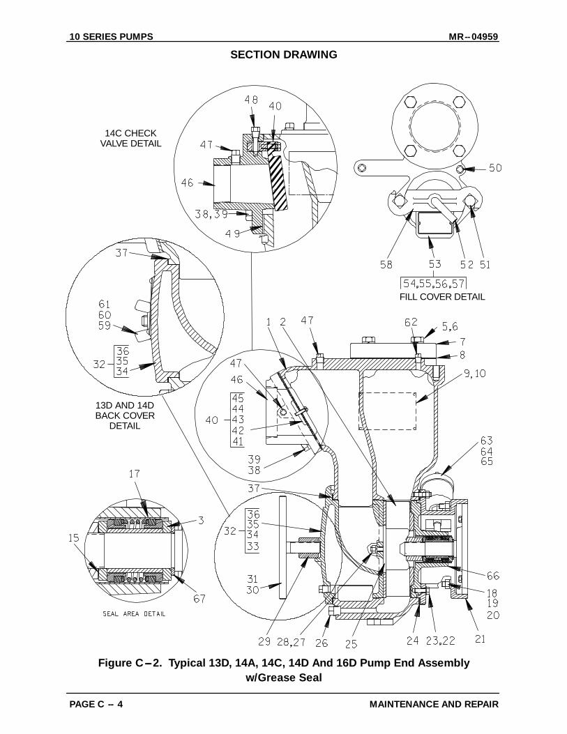
Figure C---2. Typical 13D, 14A, 14C, 14D And 16D Pump End Assemblyw/Grease Seal

ITEMNO. PART NAME
ITEMNO. PART NAME
MR--04959 10 SERIES PUMPS
PAGE C -- 5MAINTENANCE AND REPAIR
Typical 13D, 14A, 14C,14D and 16D Pump End Assembly w/Grease SealParts Identification List
Refer to the separate Parts List Manual for serviceable parts, part numbers and quantities.
1 PUMP CASING2 IMPELLER3 SEAL ASSEMBLY4 STREET ELBOW (IF REQUIRED)5 HEX HEAD CAPSCREW6 LOCKWASHER OR FLAT WASHER
(IF REQUIRED)7 DISCHARGE FLANGE8 DISCHARGE FLANGE GASKET9 NAME PLATE
10 DRIVE SCREW11 HEX HD CAPSCREW (NOT REQ.)12 IMPELLER WASHER (NOT REQ.)13 IMP SHAFT KEY (NOT REQ.)14 SLINGER RING (NOT REQ.)15 IMPELLER SHIM SET16 SHAFT SLEEVE (IF REQUIRED)17 SEAL LINER18 STUD19 LOCKWASHER OR FLAT WASHER20 HEX NUT21 INTERMEDIATE22 STUD OR LOCKWASHER23 HEX NUT OR HEX HD CAPSCREW24 CASING GSKT SET OR O-RING25 WEAR PLATE ASSEMBLY26 CASING DRAIN PLUG27 LOCKWASHER28 HEX NUT29 CLAMP BAR (IF REQUIRED)30 CLAMP BAR SCREW (IF REQUIRED)31 MACHINE BOLT (IF REQUIRED)32 BACK COVER PLATE ASSEMBLY33 ---PIPE PLUG (IF REQUIRED)34 ---BACK COVER
35 ---WARNING PLATE36 ---DRIVE SCREW37 BACK COVER GASKET38 STUD39 HEX NUT40 CHECK VALVE ASSEMBLY41 ---SMALL VALVE WEIGHT42 ---HEX HEAD CAPSCREW43 ---LOCKWASHER44 ---LARGE VALVE WEIGHT45 ---CHECK VALVE GASKET46 SUCTION FLANGE47 PIPE PLUG (IF REQUIRED)48 CHECK VALVE PIN (IF REQUIRED)49 SUCT FLANGE GSKT (IF REQUIRED)50 PIPE PLUG51 MACHINE BOLT52 CLAMP BAR SCREW53 FILL PLUG ASSEMBLY OR
FILL COVER PLATE ASSY54 ---COVER PLATE55 ---WARNING PLATE56 ---DRIVE SCREW57 ---COVER PLATE GASKET58 CLAMP BAR59 STUD60 FLAT WASHER61 WING NUT62 PIPE PLUG (IF REQUIRED)63 GREASE CUP64 PIPE NIPPLE65 PIPE COUPLING66 SEAL PLATE67 SEAL WASHER (IF REQUIRED)

10 SERIES PUMPS MR--04959
MAINTENANCE AND REPAIRPAGE C -- 6
PUMP AND SEAL DISASSEMBLYAND REASSEMBLY
Review all SAFETY information in Section A.
Follow the instructions on all tags, label and de-cals attached to the pump.
This pump requires little service due to its rugged,minimum-maintenance design. However, if it be-comes necessary to inspect or replace the wearingparts, follow these instructions which are keyed tothe sectional views (see Figure C---1 or C---2) andthe accompanying parts list. Unless otherwisespecified, the instructions apply to either FigureC---1 or Figure C---2.
Before attempting to service the pump, disconnector lock out the power source and take the neces-sary precautions to ensure that the pump will re-main inoperative. Close all valves in the suctionand discharge lines.
For power source disassembly and repair, consultthe literature supplied with the power source, orcontact your local source representative.
This manual will alert personnel toknown procedures which require spe-cial attention, to those which coulddamage equipment, and to those whichcould be dangerous to personnel. How-ever, this manual cannot possibly antici-pate and provide detailed instructionsand precautions for every situation thatmight occur during maintenance of theunit. Therefore, it is the responsibility ofthe owner/maintenance personnel toensure that only safe, established main-tenance procedures are used, and thatany procedures not addressed in thismanual are performed only after estab-lishing that neither personal safety norpump integrity are compromised bysuch practices.
Before attempting to open or service thepump:
1. Familiarize yourself with this man-ual.
2. Disconnect or shut down the pow-er source and take the necessaryprecautions to ensure that thepump will remain inoperative.
3. Allow the pump to completely coolif overheated.
4. Check the temperature beforeopening any covers, plates, orplugs.
5. Close the suction and dischargevalves.
6. Vent the pump slowly and cau-tiously.
7. Drain the pump.
If the pump is designed to pump materi-als which could cause serious illness orinjury through direct exposure oremitted fumes, wear protective cloth-ing, such as rubber gloves, face mask,and rubber apron, as necessary beforedisassembling the pump or piping.
Suction Check Valve Removal and Disassembly
(Figure C--1 or Figure C--2)
Before attempting to service the pump, remove thepump casing drain plug (26) and drain the pump.Clean and reinstall the drain plug.
(Models 13D, 14A, 14D And 16D)
To service the suction check valve assembly (40),remove the suction piping. Remove the hardware(38 and 39) securing the suction flange (46) andcheck valve assembly to the pump casing (1). Sep-arate the check valve assembly from the suctionflange.
Inspect the check valve parts for wear or damage.If replacement is required, remove the hardware

MR--04959 10 SERIES PUMPS
PAGE C -- 7MAINTENANCE AND REPAIR
(42 and 43), and separate the check valve gasket(45) and weights (41 and 44), or remove the checkvalve pin (48) and pull the complete assembly fromthe suction flange. Remove the suction flange gas-ket (49).
(Model 14C)
If the check valve assembly (40) is to be serviced,reach through the back cover opening (32) andhold the assembly in place while removing thecheck valve pin (48). Slide the assembly from thesuction flange (46) and remove it from the pump.
NOTEFurther disassembly of the check valve is not re-quired since it must be replaced as a complete unit.Individual parts are not sold separately.
The check valve assembly may also be serviced byremoving the suction flange. To remove the flange,disengage the nuts (39) and pull the flange and as-sembled check valve from the suction port. Re-move the check valve pin, and pull the check valveassembly out of the seat.
If no further disassembly is required, see SuctionCheck Valve Installation.
Back Cover Removal
(Models 14A, 14C And 16D)
The wear plate assembly (25) is easily accessibleand may be serviced by removing the back cover(32). Loosen the clamp bar screw (30) and removethe clamp bar (29). Pull the back cover and wearplate from the pump casing. Remove the back cov-er gasket (37). Clean the mating surfaces of theback cover plate and pump casing.
Inspect the wear plate and replace it if badlyscoredor worn. To remove the wear plate, disengage thehardware (27 and 28) securing it to the back cover.
(Models 13D And 14D)
Remove the wing nuts and washers (60 and 61) se-curing the back cover to the casing. Pull the backcover and wear plate from the pump casing (1).
Inspect the wear plate for excessive wear or scor-ing. If replacement is required, remove the hard-ware (27 and 28) securing it to the back cover.
Remove the cover plate gasket (37) and clean themating surfaces.
If no further disassembly is required, see BackCover Installation.
Pump Casing Removal
To service the impeller or seal assembly, discon-nect the discharge piping. Remove the hardwaresecuring the pump casing to the base. Tie and tagany leveling shims used under the pump mountingfeet to ease reassembly.
If so equipped, disengage the hardware securingthe pump casing to the hoisting bail. Support thepump casing using a suitable hoist and sling, andremove the hardware (22 and 23) securing thepump casing to the intermediate (21). Separate thepump casing and gasket set (24) from the inter-mediate by pulling the casing straight away. Cleanthe mating surfaces of the intermediate and pumpcasing. Tie and tag the gaskets, or measure andrecord their thickness for ease of reassembly.
(Model 13D)
Support the pump casing (1) using a suitable hoistand sling and remove the hardware (19 and 20) se-curing the pump casing to the intermediate. Sepa-rate the parts by pulling the casing straight awayfrom the intermediate. Remove the intermediate O-ring (24) and clean the mating surfaces.
Figure C--3. Pump Model 13D
Impeller Removal
If the pump is equipped with a grease seal, turn thecross arm on the automatic lubricating grease cup(63, Figure C---2) clockwise until it rests against thecover (see Figure C---7) before attempting to re-move the impeller (2). This will prevent the grease

10 SERIES PUMPS MR--04959
MAINTENANCE AND REPAIRPAGE C -- 8
in the cup from escaping when the impeller is re-moved.
NOTEFor close-coupled electric motor driven models,use a screwdriver or other suitable tool to immobi-lize the motor shaft before attempting to remove theimpeller.
(Models 13D, 14A, 14D And 16D)
To loosen the impeller (2), tap the vanes of the im-peller in a counterclockwise direction (when facingthe impeller) with a block of wood or a soft-facedmallet. Unscrew the impeller using caution; ten-sion on the seal spring will be released as the im-peller is unscrewed.
Inspect the impeller and replace it if cracked orbadly worn. Slide the impeller adjusting shims (15)off the impeller shaft. Tie and tag the shims or mea-sure and record their thickness for ease of reas-sembly.
(Model 14C and 14D)
Remove the impeller hardware (11 and 12) and usea suitable puller to remove the impeller from theshaft. Save the impeller shaft key (13).
Inspect the impeller and replace it if cracked orbadly worn. Slide the impeller adjusting shims (15)off the impeller shaft. Tie and tag the shims or mea-sure and record their thickness for ease of reas-sembly.
Self Lubricated Seal Removal And Disassembly
(Figures C--1 and C--4)
Remove the spring centering washer (16) and sealspring. Slide the shaft sleeve (17) and rotating por-tion of the seal off the shaft as a single unit. Applyoilto the sleeve and work it up under the bellows.Slide the rotating portion of the seal off the shaft.Use a pair of stiff wires with hooked ends to removethe stationary seat and O-rings from the intermedi-ate (21).
NOTEAn alternate method of removing the seal assembly
is to remove the hardware securing the intermedi-ate to the power source and slide the intermediateand seal assembly off the shaft as a single unit.Place the intermediate on a flat surface with the im-peller side down. Use a suitable sized dowel topress the seal components from the intermediate.
Remove the slinger ring (14, if so equipped). If re-quired, remove the intermediate as describedabove.
If no further disassembly is required, see Self Lu-bricated Seal Installation.
Grease Seal Removal and Disassembly
(Figures C--2 and C--5)
To remove the seal assembly (3), remove thegrease cup and piping (63, 64 and 65) from the in-termediate (21) or the seal plate (66).
Carefully remove the outer stationary and rotatingseal elements, packing ring, stationary washer,seal spring, and spacer sleeve from the intermedi-ate. Using two stiff wires with hooked ends, removethe inboard stationary washer, packing ring andstationary and rotating seal elements.
NOTEThe seal assembly may also be removed by disen-gaging the hardware securing the intermediate tothe power source and sliding the intermediate andseal assembly off the shaft as a single unit. Use adowel of suitable size to press the seal componentsfrom the intermediate.
Inspect the seal liner for wear or grooves whichcould cause leakage or damage to the seal pack-ing rings. The seal liner is a press fit in the inter-mediate or seal plate and does not normally re-quire replacement. If replacement is necessary,separate the intermediate from the power sourceas described above. Remove the seal washer (67).
If the seal liner needs replaced, see Grease SealReassembly and Installation.
If no further disassembly is required, see GreaseSeal Reassembly and Installation.

MR--04959 10 SERIES PUMPS
PAGE C -- 9MAINTENANCE AND REPAIR
Seal Installation
(Figures C-1 C--4 and C--5)
Clean the seal cavity and shaft with a cloth soakedin fresh cleaning solvent.
Most cleaning solvents are toxic andflammable. Use them only in a well ven-tilated area free from excessive heat,sparks, and flame. Read and follow allprecautions printed on solvent contain-ers.
Inspect the shaft for damage. Small scratches ornicks may be removed with a fine file or emerycloth. If excessive wear exists, the shaft will have tobe replaced. (Refer to the power source servicemanual).
The seal is not normally reused because wear pat-terns on the finished faces cannot be realignedduring reassembly. This could result in prematurefailure. If necessary to reuse an old seal in an emer-gency, carefully wash all metallic parts in freshcleaning solvent and allow to dry thoroughly.
Handle the seal parts with extreme care to preventdamage. Be careful not to contaminate precisionfinished faces; even fingerprints on the faces canshorten seal life. If necessary, clean the faces with anon-oil based solvent and a clean, lint-free tissue.Wipe lightly in a concentric pattern to avoidscratching the faces.
Inspect the seal components for wear, scoring,grooves, and other damage that might cause leak-age. If any components are worn, replace the com-plete seal; never mix old and new seal parts.
Self Lubricated Seal Reassembly And Installa-tion
(Figures C--1 and C--4)
Clean and polish the shaft sleeve (17), or replace itif there are nicks or cuts on either end. If a replace-ment seal is being used, remove it from the con-tainer and inspect the precision finished faces toensure that they are free of any foreign matter.
To ease installation of the seal, lubricate the O-rings and shaft sleeve with water or a very smallamount of oil, and apply a drop of light lubricatingoil on the finished faces. Assemble the seal as fol-lows, (see Figure C---4).
ROTATING ELEMENT
SLEEVE
STATIONARYSEAT
SHIMS
SPRINGCENTERING
WASHERDRIVE BAND
SLINGER RINGBELLOWS
O-RINGSSPRING
Figure C--4. Self Lubricated Seal Assembly
This seal is not designed for operation attemperatures above 160_F (71_C). Do notuse at higher operating temperatures.
If the intermediate (21) was removed, position theintermediate over the shaft and secure it to thepower source with the previously removed hard-ware.
If used, install the slinger ring (14) on the shaft.
Press the stationary subassembly (consisting ofthe stationary seat and O-ring) into the intermedi-ate until the stationary seat bottoms against the in-termediate bore. A push tube cut from a length ofplastic pipe would aid this installation. The I.D. ofthe pipe should be approximately the same diame-ter as the I.D. of the seal spring.
Slide the rotating subassembly (consisting of therotating element, retainer and bellows) onto the lu-bricated shaft sleeve until the rotating element isjust flush with the end of the sleeve with the cham-fered I.D. Slide the sleeve and rotating subassem-bly onto the shaft until the seal faces contact. Con-

10 SERIES PUMPS MR--04959
MAINTENANCE AND REPAIRPAGE C -- 10
tinue to push the sleeve through the seal until it bot-toms against the shaft shoulder.
Install the seal spring and spring centering washer(16).
Grease Seal Reassembly And Installation
(Figures C--2 and C--5)
Before installing the seal, inspect the bore of theseal liner (17) for wear or grooves which mightcause leakage or damage to the seal packingrings. If the seal liner must be replaced, positionthe intermediate or seal plate (21) on the bed of anarbor (or hydraulic) press. Use a new sleeve toforce the old one out. After the new liner is properlyinstalled, drill a 1/4-inch diameter hole through theliner to permit the flow of lubricant to the seal as-sembly. Be careful to center the drill in thethreaded grease piping hole and not damage thethreads. Deburr the hole from the inside of the sealliner after drilling.
To ease installation of the seal, lubricate the pack-ing rings and seal liner with water or a very smallamount of oil, and apply a drop of light lubricatingoil on the finished faces. Assemble the seal as fol-lows, (see Figure C---5).
SHAFT
SEALLINER
IMPELLER
IMPELLERSHIMS
STATIONARY WASHERSROTATINGELEMENT
SPRING SEAL PLATE
PACKINGRINGSPACER
SLEEVE
STATIONARYELEMENT
Figure C--5. Grease Seal Assembly
This seal is not designed for operation at
temperatures above 110_F (43_C). Do notuse at higher operating temperatures.If so equipped, install the seal plate (66) on the in-termediate. Install the seal washer (67, if required).
RADIUSINBOARD ELEMENT
CHAMFER TOWARDSHOULDER
CHAMFER AWAYFROM SHOULDER
INBOARD ELEMENT UNDERCUT
SHAFT
SHAFT
Figure C--6. Positioning of Inboard Element
The position for the inboard rotating element is de-termined by the machining of the impeller shaft atthe shoulder where the element seats. See FigureC---6, if there is a radius on the shaft, position theinboard element with the I.D. chamfer toward theshaft shoulder. If the shaft is undercut at the shoul-der, position the inboard element with the I.D.chamfer away from the shoulder.
Subassemble the inboard stationary element,packing ring and seal washer. Press this unit intothe lubricated seal liner until the seal faces contact.A push tube cut from a length of plastic pipe wouldaid this installation. The I.D. of the tube should beapproximately the same as the the I.D. of the sealspring.
Install the spacer sleeve and seal spring.
Subassemble the outboard stationary element,packing ring and seal washer. Press this unit intothe lubricated seal liner.
Install the outboard rotating element with thechamfered side toward the impeller end of theshaft.
Install the grease cup and the piping (63, 64 and65) in the intermediate.
After the impeller has been installed, lubricate theseal as indicated in LUBRICATION at the end ofthis section.
MR--04959 10 SERIES PUMPS
PAGE C -- 11MAINTENANCE AND REPAIR
NOTESome smoking and leakage may occur after instal-ling a new seal assembly. This should stop after thepump has run a while and the lapped seal faceshave seated in.
Impeller Installation And Adjustment
Inspect the impeller, and replace it if cracked orbadly worn. Install the same thickness of impelleradjusting shims (15) as previously removed, andscrew the impeller onto the shaft until tight.
For maximum pump efficiency, a specific clear-ance is required between the impeller and the in-termediate or seal plate (see Table C---1). This backclearance can be achieved by adding or removingimpeller shims.
NOTEBe sure the intermediate or seal plate is securedwhile measuring this clearance.
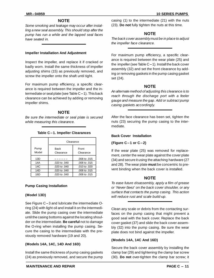
Table C--1. Impeller Clearances
13D --- --- --- --- --- --- .008 to .01514A .020 to .040 .008 to .01514C .020 to .040 .010 to .02014D .020 to .040 .008 to .01516D .020 to .040 .008 to .015
PumpModel
FrontClearance
Clearance
BackClearance
Pump Casing Installation
(Model 13D)
See Figure C---3 and lubricate the intermediate O-ring (24) with light oil and install it on the intermedi-ate. Slide the pump casing over the intermediateuntil the casing bottoms against the locating shoul-der on the intermediate. Be careful not to damagethe O-ring when installing the pump casing. Se-cure the casing to the intermediate with the pre-viously removed hardware (19 and 20).
(Models 14A, 14C, 14D And 16D)
Install the same thickness of pump casing gaskets(24) as previously removed, and secure the pump
casing (1) to the intermediate (21) with the nuts(23). Do not fully tighten the nuts at this time.
NOTEThe back cover assembly must be in place to adjustthe impeller face clearance.
For maximum pump efficiency, a specific clear-ance is required between the wear plate (25) andthe impeller (see Table C---1). Install the back coverassembly (32) and set the front clearance by add-ing or removing gaskets in the pump casing gasketset (24).
NOTEAn alternate method of adjusting this clearance is toreach through the discharge port with a feelergauge and measure the gap. Add or subtract pumpcasing gaskets accordingly.
After the face clearance has been set, tighten thenuts (23) securing the pump casing to the inter-mediate.
Back Cover Installation
(Figure C--1 or C--2)
If the wear plate (25) was removed for replace-ment, center the wear plate against the cover plate(34) and secure it using the attaching hardware (27and 28). The wear plate must be concentric to pre-vent binding when the back cover is installed.
NOTETo ease future disassembly, apply a film of greaseor ‘Never-Seez’ on the back cover shoulder, or anysurface that contacts the pump casing. This actionwill reduce rust and scale build-up.
Clean any scale or debris from the contacting sur-faces on the pump casing that might prevent agood seal with the back cover. Replace the backcover gasket (37) and slide the back cover assem-bly (32) into the pump casing. Be sure the wearplate does not bind against the impeller.
(Models 14A, 14C And 16D)
Secure the back cover assembly by installing theclamp bar (29) and tightening the clamp bar screw(30). Do not over-tighten the clamp bar screw; it
10 SERIES PUMPS MR--04959
MAINTENANCE AND REPAIRPAGE C -- 12
should be just tight enough to ensure a good sealat the back cover shoulder.
(Models 13D And 14D)
Secure the back cover assembly with the hard-ware (60 and 61). Do not over tighten the wingnuts; they should be just tight enough to ensure agood seal at the back cover shoulder.
Suction Check Valve Installation
(Figure C--1 or C--2)
Inspect the check valve components and replaceas required. Subassemble the check valve weights(41 and 44) and check valve gasket (45) using theattaching hardware (42 and 43).
Position the check valve assembly (40) in the suc-tion port with the large weight toward the inside ofthe pump casing. Install the suction flange (46) andsecure with the hardware (38 and 39). Check theoperation of the check valve to ensure proper seat-ing and free movement.
(Model 14C)
NOTEThe check valve assembly (40) for Model 14C mustbe replaced as a complete unit. Individual parts arenot sold separately.
Position the check valve adaptor in the mountingslot of the suction flange (46). Align the adaptorwith the flange hole, and secure the assembly withthe check valve pin (48). Install the suction flangeand suction flange gasket (49), and secure with thehardware (38 and 39). Check the operation of thecheck valve to ensure proper seating and freemovement.
Final Pump Assembly
Secure the pump to the base with the previously re-moved hardware. Be sure to reinstall any levelingshims used under the pump mounting feet.
Be sure the pump and power source are securelymounted to the base.
Install the suction and discharge lines. Make cer-tain that all piping connections are tight, properlysupported and secure. Open all the valves in thesuction and discharge lines.
Be sure the pump and power source have beenproperly lubricated, see LUBRICATION.
Remove the fill plug assembly/fill cover plate as-sembly (53) and fill the pump casing with clean liq-uid. Reinstall the fill plug and tighten it.
Refer to OPERATION in the Installation And Op-eration manual before putting the pump back intoservice.
LUBRICATION
Self Lubricated Seal Assembly
(Figure C--1)
The seal assembly is lubricated by the medium be-ing pumped, or by a flow of fresh liquid from an ex-ternal source. Flushing liquid may be taken fromthe pump discharge and supplied through auxilia-ry piping.
When handling abrasive or tacky liquids, supplyfresh lubricating liquid from an external source. Besure the liquid supplied to the seal is compatiblewith the liquid being pumped, and that its flow iscontrolled to prevent dilution. If flushing is re-quired, contact the factory.
Grease Lubricated Seal Assembly
(Figure C--2)
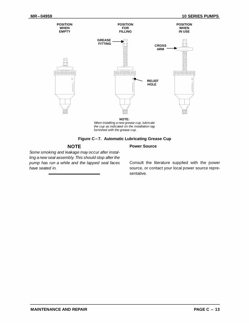
Fill the grease cup (63) through the grease fittingwith No. 2 lithium base grease until grease es-capes from the relief hole. Turn the grease cup armcounterclockwise until it is at the top of the stem;this will release the spring to apply grease to theseal (see Figure C---7).
MR--04959 10 SERIES PUMPS
PAGE C -- 13MAINTENANCE AND REPAIR
GREASEFITTING CROSS
ARM
POSITIONWHENEMPTY
POSITIONFOR
FILLING
POSITIONWHENIN USE
RELIEFHOLE
NOTE:When installing a new grease cup, lubricatethe cup as indicated on the installation tagfurnished with the grease cup.
Figure C--7. Automatic Lubricating Grease Cup
NOTESome smoking and leakage may occur after instal-ling a new seal assembly. This should stop after thepump has run a while and the lapped seal faceshave seated in.
Power Source
Consult the literature supplied with the powersource, or contact your local power source repre-sentative.

THE GORMAN-RUPP COMPANY F MANSFIELD, OHIOGORMAN-RUPP OF CANADA LIMITED D ST. THOMAS, ONTARIO, CANADA Printed in
U.S.A.
July 18, 1979
WARRANTY
Pumping units manufactured by The Gorman-Rupp Company,Mansfield, Ohio are guaranteed to be free from defects in mate-rial and workmanship for one year from date of shipment fromfactory in Mansfield, Ohio. The obligation under this Warranty,statutory or otherwise, is limited to replacement or repair atMansfield, Ohio factory or at a point designated by Gorman-Rupp, of such part as shall appear to us upon inspection at suchpoint, to have been defective in material or workmanship.
This Warranty does not obligate The Gorman-Rupp Company tobear the cost of labor or transportation charges in connectionwith replacement or repair of defective parts; nor shall it apply toa pump upon which repairs or alterations have been made un-less authorized by Gorman-Rupp.
No warranty is made in respect to engines, motors, or trade ac-cessories, such being subject to warranties of their respectivemanufacturers.
In Submersible Pumps, pump and motor are integral and Sub-mersibles are warranted as a unit. Since motor is subject to animportant degree upon quality and performance of electricalcontrols, unit warranty is valid only when controls have beenspecified and provided by Gorman-Rupp.
No express implied or statutory warranty, other than herein setforth is made or authorized to be made by Gorman-Rupp.
In no event shall The Gorman-Rupp Company be liable for con-sequential damages or contingent liabilities arising out of the fail-ure of any Gorman-Rupp pump or parts thereof to operate prop-erly.
THE GORMAN-RUPP COMPANY
Mansfield, Ohio
NOTE: In Canada, all above references to “The Gorman-RuppCompany, Mansfield, Ohio” is understood to mean “Gorman-Rupp of Canada Limited, St. Thomas, Ontario.”
ECopyright by the Gorman-Rupp Company