1.0 Introduction - futuretech.blinkenlights.nlfuturetech.blinkenlights.nl/onyx/IR_techreport.pdf ·...
42
Introduction InfiniteReality Technical Report 1 1.0 Introduction Silicon Graphics, the recognized leader in developing sophisticated visual computing systems, is dedicated to advancing three-dimensional computer graphics technologies. After more than a decade, hardware and software solutions from Silicon Graphics con- tinue to redefine the state of the art in visual computing for creative professionals, scien- tists, and engineers. InfiniteReality is the latest offering in the most advanced line of binary-compatible visualization systems. It establishes a new high-water mark for 3D geometry processing performance and concurrently processes 3D geometry, imagery, and video data in real time — making it a true visualization pipeline capable of process- ing a broad range of visual data types. 1.1 System Configurations InfiniteReality systems are packaged in both compact deskside units for optimal price/ performance and larger rack units for maximum performance and expansion. They are available in the following configurations: • Onyx® – Multiprocessor Graphics Workstation Onyx systems combine the InfiniteReality graphics system with the shared-memory multiprocessing capability of the POWERpath-2™ RISC system architecture. Onyx systems are available with two to 24 MIPS® R4400® or MIPS R10000™ proces- sors, in both deskside (Figure 1) and rack enclosures (Figure 2). Figure 1. InfiniteReality Deskside System Block Diagram (includes Sirius Video option) 2 to 4 R4400 or R10000 CPUs 64MB to 2GB System Memory POWERpath-2 System Bus Geometry Engine (GE12) Raster Manager (RM6) POWERchannel-2 Sirius Video Option Video In Video In/Out Display Generator (DG4)
Transcript of 1.0 Introduction - futuretech.blinkenlights.nlfuturetech.blinkenlights.nl/onyx/IR_techreport.pdf ·...

Introduction
1.0 Introduction
Silicon Graphics, the recognized leader in developing sophisticated visual computing systems, is dedicated to advancing three-dimensional computer graphics technologies. After more than a decade, hardware and software solutions from Silicon Graphics con-tinue to redefine the state of the art in visual computing for creative professionals, scien-tists, and engineers. InfiniteReality is the latest offering in the most advanced line of binary-compatible visualization systems. It establishes a new high-water mark for 3D geometry processing performance and concurrently processes 3D geometry, imagery, and video data in real time — making it a true visualization pipeline capable of process-ing a broad range of visual data types.
1.1 System Configurations
InfiniteReality systems are packaged in both compact deskside units for optimal price/performance and larger rack units for maximum performance and expansion. They are available in the following configurations:
• Onyx® – Multiprocessor Graphics Workstation
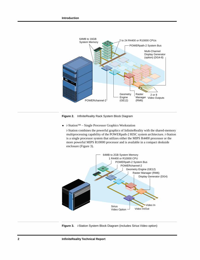
Onyx systems combine the InfiniteReality graphics system with the shared-memory multiprocessing capability of the POWERpath-2™ RISC system architecture. Onyx systems are available with two to 24 MIPS® R4400® or MIPS R10000™ proces-sors, in both deskside (Figure 1) and rack enclosures (Figure 2).
Figure 1. InfiniteReality Deskside System Block Diagram (includes Sirius Video option)
2 to 4 R4400 or R10000 CPUs64MB to 2GB System Memory
POWERpath-2 System Bus
Geometry Engine (GE12)Raster Manager (RM6)
POWERchannel-2
SiriusVideo Option
Video InVideo In/Out
Display Generator (DG4)
InfiniteReality Technical Report 1
Introduction
Figure 2. InfiniteReality Rack System Block Diagram
• i-Station™ – Single Processor Graphics Workstation
i-Station combines the powerful graphics of InfiniteReality with the shared-memory multiprocessing capability of the POWERpath-2 RISC system architecture. i-Station is a single processor system that utilizes either the MIPS R4400 processor or the more powerful MIPS R10000 processor and is available in a compact deskside enclosure (Figure 3).
Figure 3. i-Station System Block Diagram (includes Sirius Video option)
64MB to 16GB System Memory
2 to 24 R4400 or R10000 CPUs
POWERpath-2 System Bus
Geometry Engine (GE12)
Raster Manager(RM6)
Multi-ChannelDisplay Generator(option) (DG4-8)
POWERchannel-2
Computer Systems
SiliconGraphics
2 or 8Video Outputs
1 R4400 or R10000 CPU64MB to 2GB System Memory
POWERpath-2 System Bus
Geometry Engine (GE12)Raster Manager (RM6)
POWERchannel-2
SiriusVideo Option
Video InVideo In/Out
Display Generator (DG4)
2 InfiniteReality Technical Report

Introduction
• POWER CHALLENGE™ GR – Supercomputing Server
POWER CHALLENGE, the premier supercomputing system from Silicon Graphics, is based on the POWERpath-2 RISC system architecture. POWER CHALLENGE GR is designed to operate with the InfiniteReality subsystem, giving you supercom-puting performance and the world’s most powerful visualization system. This rack system can use up to 24 MIPS R10000 processors.
I/O devices connect to these systems through the Silicon Graphics® High-speed I/O bus (HIO bus) or through an industry-standard VME64 bus. Options are available to connect high-bandwidth SCSI-2 disk array subsystems, FDDI, ATM, and high-speed point-to-point interfaces (HIPPI) into the I/O subsystem. Multiple I/O buses can be used in all configurations.
1.2 About this Document
This document serves as a detailed report on InfiniteReality subsystems. For in-depth technical information on the CPU, memory, and I/O subsystems of the Onyx and POWER CHALLENGE families, see the CHALLENGE® and POWER CHALLENGE technical reports. These reports are available through local Silicon Graphics sales offices worldwide.
InfiniteReality Technical Report 3

Introduction
(Intentionally left blank)
4 InfiniteReality Technical Report
InfiniteReality
2.0 InfiniteReality
InfiniteReality is specifically designed to concurrently process 3D geometry, imagery and video data at real-time rates, making it much more than a traditional 3D graphics processing system. It is a true visualization pipeline capable of processing a broad range of visual data types. The new advanced feature set in InfiniteReality combines its raw processing power and I/O speeds, making it the most powerful computer graphics sys-tem in the world. Compatibility between InfiniteReality and other systems is assured because the hardware is accessed through OpenGL, developed by Silicon Graphics and now accepted as the world standard for creating 3D graphics applications.
As in its predecessor RealityEngine2™, the InfiniteReality visualization subsystem comprises three unique boards: Geometry Engine, the RM (Raster Manager), and the DG (Display Generator). Geometry Engine provides the interface to the compute sub-system through the POWERchannel-2 board and is responsible for the preliminary geo-metric transformations (translation, rotation, scale) and lighting calculations for three-dimensional data. It also performs image processing functions (convolution, histogram equalization, orthorectification, and more) on two-dimensional images. The Raster Manager takes the results from Geometry Engine and scan-converts the data into a digi-tal image. The RM board performs various pixel operations, including Z-buffer testing, color and transparency blending, texture mapping, and multisample anti-aliasing. The RM has both texture memory for storing textures (images) and frame buffer memory for performing pixel operations. Finally, the DG board takes the output from the RM board and converts the digital data into an analog format for driving a display. A base DG can be programmed to display different portions of the RM frame buffer to its two display channels. One of these display channels can be converted into a composite video mode and connected directly to a video tape recorder. Optional configurations of the DG board permit up to eight output display channels.
InfiniteReality employs an entirely new system architecture. Thirteen unique ASIC (Application Specific Integrated Circuit) designs comprising 19 million transistors were developed using the latest in semiconductor design and fabrication technologies. Sev-eral designs are used multiple times in each pipeline. A maximally configured pipeline contains 151 ASICS with more than 260M transistors. In general terms, the processors make up stages in a pipeline. Within each stage additional parallelism is obtained by employing SIMD and MIMD techniques.
InfiniteReality Technical Report 5

InfiniteReality
(Intentionally left blank)
6 InfiniteReality Technical Report

OpenGL
3.0 OpenGL
The native graphics programming interface for InfiniteReality is OpenGL, the premier environment for developing high-performance 2D graphics, 3D graphics, imaging, and video applications. It is designed to be independent of operating systems and window systems, and is supported on virtually all workstations and personal computers available in the industry today.
Standard OpenGL provides access to a rich set of graphics capabilities, including transformations, lighting, atmospheric effects, texturing, anti-aliasing, hidden surface removal, blending, and pixel processing, among many others. On InfiniteReality, OpenGL adds more than 30 special functions for applications in visual simulation, imaging, vol-ume rendering, advanced industrial design, film and video effects, and animation.
OpenGL is a direct descendant of the original IRIS Graphics Library™ (IRIS GL™). On InfiniteReality, IRIS GL is implemented as a library layered on top of OpenGL. However, the special features and full performance of InfiniteReality are available only through OpenGL.
InfiniteReality Technical Report 7

OpenGL
(Intentionally left blank)
8 InfiniteReality Technical Report

Geometry Subsystem
4.0 Geometry Subsystem
The first stage in the InfiniteReality system is the geometry subsystem. It resides on the Geometry Engine (GE) board. The primary functions of the geometry subsystem are handling data transfer to and from the host, performing OpenGL command parsing, and executing geometry and pixel processing commands. The geometry subsystem has been substantially modified compared to over the design used in RealityEngine2: for the first time, the system provides dedicated hardware acceleration for display list processing; the I/O rate to and from the host as well as internally within the subsystem is much higher; floating point processing power was increased substantially. Additionally, the geometry subsystem for InfiniteReality was designed to support the OpenGL API. Large FIFOs are provided to ensure that the geometry subsystem can continue executing with-out stalling, regardless of the state of other stages within the pipeline.
4.1 Geometry Engine
Geometry Engine processors are custom-designed by Silicon Graphics. Four Geometry Engine processors are employed in MIMD fashion within the geometry subsystem. Each Geometry Engine processor contains three separate floating-point cores that exe-cute in SIMD. Each core contains a floating-point ALU and multiplier.
Geometry Engine processors do both geometry (per vertex) and pixel processing. Geometry processing includes vertex transformations, lighting, clipping, and projection to screen space. Pixel processing includes many common image processing operators, such as convolution, histograms, scale and bias, and lookup tables. Pixel operations can be applied to standard pixels, textures, or video.
InfiniteReality Technical Report 9

Geometry Subsystem
(Intentionally left blank)
10 InfiniteReality Technical Report

Raster Subsystem
5.0 Raster Subsystem
The raster subsystem, residing on the Raster Manager boards, has most of the graphics system’s custom VLSI processors and memory. Triangle, point, and line data received by the Raster Manager from the geometry subsystem must be scan-converted into pixel data, then processed into the frame buffer before a finished rendering is handed to the display subsystem for generation of displayable video signals.
By using extensive parallelism in most stages, the raster subsystem creates a system that performs anti-aliasing, texture mapping, and image processing functions without en-countering bottlenecks. The method of performing anti-aliasing is called multisampling. With multisampling, images are rendered into a frame buffer with a higher effective res-olution than that of the displayable frame buffer; the number of subsamples computed for each pixel determines how much higher. For example, if each pixel has eight sub-samples, positioned at eight of the 64 possible subpixel locations, then the effective resolution is eight-times the displayable resolution.
When the image has been rendered into these subsamples, all samples that belong to each pixel are blended together to determine pixel colors. Image memory is interleaved among parallel processors so that adjacent pixels are always handled by different pro-cessors. Thus, each polygon can have multiple processors operating on it in parallel.
5.1 Texture Processing
For each pixel, scan conversion produces texture coordinate data (S, T, R, W) which are sent to a dedicated texture processing unit. This hardware performs perspective correc-tion on texture coordinates, and determines the detail level for MIPmapping, producing addresses for the relevant area of texture memory. Texture data (texels) are stored in one of several formats, depending on the number and precision of color and transparency components desired. Texels in the area covered by a pixel are read and used in one of several user-definable texture filtering calculations. The resulting color value is sent to pixel processors to rendezvous with the pre-texture color and depth values produced by the main scan converter.
5.2 Pixel Processing
At the next stage of rendering, texture color is used to modify the pre-texture primitive color according to a texture environment equation. Here is where texture can be used to decal, modulate, or blend with the underlying primitive color. The amount of fog at the current pixel is calculated from the depth value, and this fog color is blended with the textured color to produce the final color and transparency.
Pixel processors support 10-bit RGB and 12-bit RGBA components for pixels, giving you the option of selecting from more than 68 billion colors for any given object or ver-tex. 16-bit luminance-alpha or color index formats are also supported. This accurate color information is critical for image processing applications and is supported through Silicon Graphics ImageVision Library, as well as OpenGL.
InfiniteReality Technical Report 11

Raster Subsystem
The raster subsystem supports one to four Raster Manager boards. More boards increase the scale of both pixel fill performance and frame buffer resolution. With one RM board installed, InfiniteReality systems support the new ultra-high-resolution standard of 1920 x 1200 pixels non-interlaced and the full specification for HDTV, offering inter-laced displays that use either the 1250/50 (1920 x 1152 display resolution) or 1125/60 format (1920 x 1035 resolution).
12 InfiniteReality Technical Report

Display Subsystem
6.0 Display Subsystem
The InfiniteReality video display subsystem takes rendered images from the raster sub-system digital frame buffer and processes pixels through digital-to-analog converters (DACs) to generate an analog pixel stream suitable for display on a high-resolution RGB video monitor. The display subsystem supports programmable pixel timings to allow the system to drive displays with a wide variety of resolutions, refresh rates, and interlace/non-interlace characteristics.
The standard configuration of InfiniteReality provides two or eight independent video channels. The second video channel can serve as a standard RGB video channel, as a composite, or as an S-video encoder. Flexible, built-in scan-conversion allows the video encoder to process any rectangular area of any video channel, up to and including the full screen. Convenient letterboxing lets the composite encoder work undistorted on video formats with aspect ratios other than the 3:4 aspect ratio of NTSC or PAL.
Advanced hardware in the video display subsystem performs real-time video resamp-ling, giving you powerful new methods of guaranteeing scene update-rates and using frame buffer memory efficiently, as well as allowing full-screen recording to standard VCRs. Compatibility with a wide variety of video equipment such as projectors and recorders, is provided by composite sync-on-green and separate horizontal and vertical video signals.
Composite and S-video encoder outputs are for industrial or monitoring purposes only, and are not intended for broadcast television use. For broadcast-quality composite video, a video channel may be configured as RS-170 or Euro 625 resolution and sent through an external, broadcast-quality encoder. When CCIR601 or broadcast-quality component video is desired, the Sirius Video option may be used. In InfiniteReality, the Sirius Video option can access frame buffer memory in the same way as any other video channel.
The display system provides standard video support for the US HDTV standard (SMPTE 274M, 1920 x 1080 pixels), both interlaced and non-interlaced, at 60Hz. HDTV trilevel sync is provided for easy recording of HDTV signals without external signal conditioning equipment. Additionally, a special 72Hz non-interlaced version of this format is provided for flicker-free viewing in ambient office lighting environments. The 1920 x 1080 pixel format is supported on the entry-level, 1-RM configuration of InfiniteReality. This video flexibility is supported by the standard system monitor, which is a high-resolution multisync display capable of displaying any video signal from VGA (640 x 480) up to the 1920 x 1080 format.
Video features of InfiniteReality are easy to configure, using the new Video Format Compiler and Video Format Combiner.
InfiniteReality Technical Report 13

Display Subsystem
(Intentionally left blank)
14 InfiniteReality Technical Report
Graphics Features and Capabilities
7.0 Graphics Features and Capabilities
7.1 Resolution
InfiniteReality supports a range of resolutions. The base system includes one Raster Manager board and provides 2.62 million pixels. 2-RM and 4-RM systems offer 5.24 million and 10.48 million pixels, respectively. For example, a 1-RM system can drive a 1920 x 1080 HDTV display or two 1280 x 1024 displays. Alternately, a 2-RM system can drive six 960 x 720 displays or one 1280 x 1024 plus six 800 x 600 displays.
The minimum amount of frame buffer memory you can allocate per pixel is 256 bits, which supports quad-buffered stereo with up to 12-bit RGBA and a 23-bit depth buffer, or 4-sample antialiasing at 10-bit RGB with a 23-bit precision depth buffer. Per-pixel memory can be doubled or quadrupled, with a corresponding reduction to one-half or one-quarter of available pixels.
7.2 Graphics Primitives
The general-purpose InfiniteReality graphics pipeline supports a wide range of graphics primitives for constructing and rendering real-time 3D objects. The basic primitives are polygons, vectors, points, and parametric polynomial surfaces (such as NURBS and Bezier patches). These primitives may be rendered with color, transparency, lighting, texture, and various surface properties.
For complex, contiguous surfaces, such as terrain, polygons may be meshed into strips with common vertices. This reduces system transformation demands and efficiently uses the inherent parallelism in the InfiniteReality pipeline.
7.3 Transformations
OpenGL supports two mechanisms for delivering data to the rendering pipeline: imme-diate mode and display list mode. In immediate mode, transformations, geometry, as well as other data are delivered to the rendering pipeline directly from the application by calling a series of OpenGL routines. For example:
glBegin(GL_TRIANGLE_STRIP);
glVertex3fv(vertex)
...
glEnd()
Immediate mode has maximum flexibility because the application can recompute data as it sends it.
Additionally, the application can compile immediate mode commands into display lists, stored as part of the OpenGL rendering state. The application can execute display lists wherever it normally uses immediate mode commands. The advantages of display lists
InfiniteReality Technical Report 15

Graphics Features and Capabilities
are that rendering data is stored in an efficient representation and can be issued to the rendering pipeline with maximum performance. The disadvantages are that extra stor-age is required for the rendering data; and some small amount of overhead is incurred in executing the list, so lists are not suitable for small amounts of data (a single triangle, for example). Finally, display lists are usually inappropriate for dynamic data because they need to be recompiled whenever data changes. While the basic character of display modes and immediate modes are the same across the Silicon Graphics product line, some features and characteristics specific to InfiniteReality are worth noting.
7.3.1 Immediate Mode
Rendering on Silicon Graphics platforms is typically split into a three-stage pipeline:
• Data delivery: host to rendering pipeline
• Geometric processing
• Rasterization
Performance bottlenecks can occur in any of the three stages. With the improvements in the geometry and raster processing power of InfiniteReality, applications may find that the performance bottleneck is in delivering data to the rendering pipeline. Performance may be improved by tuning the algorithms through which the application traverses its data and by using suitable OpenGL commands for delivering data to the pipeline. For example, rather than using floating-point data types for colors, normals, and texture coordinates, it may be more efficient to use short or byte integer data types, reducing the bandwidth requirement to the host memory subsystem and to the rendering pipeline.
InfiniteReality also supports vertex arrays, which allow the application to issue primi-tive data to the geometry engines in larger transfers and with lower overhead compared to the standard “fine-grain” OpenGL interface. InfiniteReality extends the original OpenGL vertex array extension with support for packed vertex arrays, helping vertex arrays to be dispatched more efficiently while permitting tight packing of vertex coordi-nates and associated attributes.
7.3.2 Display Lists
Display lists are an excellent way of ensuring that data is being efficiently delivered to a rendering pipeline. InfiniteReality supports two new features for substantially improved display list performance over immediate mode performance.
The first feature is a large display list storage cache built into the rendering pipeline. This cache is approximately 14MB and can deliver data to the geometry subsystem at more than 300MB/second with very low latency. The cache is automatically managed by a combination of Performer™ and the OpenGL library. Display lists are selected for placement in the cache based on their size and their content. For example, very short lists will not be put in the cache since the overhead for executing them would outweigh the benefit of placing them in the cache. Lists containing a complex hierarchy will be excluded from the cache as the hierarchy traversal is too complex to deal with directly in the graphics pipeline.
16 InfiniteReality Technical Report

Graphics Features and Capabilities
The second display list feature allows display lists to be stored in host memory, but accessed directly by the graphics pipeline. As display lists are compiled they are stored in host memory in a representation suitable for direct interpretation by Geometry Engine. When display lists are executed, the data does not need to be processed by the host CPU nor does it pass through any of the host CPU system caches. On Onyx sys-tems the bandwidth for these direct access display lists is better than 175MB/sec.
7.3.3 Primitive Processing
InfiniteReality has features for helping applications make better use of the Geometry Engine processors. One feature is the ability to perform per-vertex processing, such as viewing and lighting computations on multiple primitives in one group. When primitives such as triangle strips are issued by the application, the vertices are accumulated and processed in batches. Geometry Engine processors and associated firmware are opti-mized for a particular batch length, usually around 6-12 vertices. In previous architec-tures, there could be only one primitive in a batch and a single primitive could span multiple batches. This meant that there was an optimal primitive size, with some perfor-mance degradation occurring for primitives of shorter or longer lengths. Now, Infinite-Reality can process multiple primitives within the same batch, so it does not incur those performance degradations.
7.3.4 Sprites
Visual simulation applications frequently need to perform computationally intensive viewing transformations for drawing sprite objects, such as trees, in which the object rotates as the view changes. InfiniteReality provides a sprite OpenGL extension for per-forming these complex calculations in the Geometry Engine processors, thus freeing up the host processor for other computations.
7.4 Color
All OpenGL color and lighting models are supported within the InfiniteReality architec-ture. Lighting operations are performed in floating point in the Geometry Engine pro-cessors. Color rasterization operations are performed by the raster subsystem with 48-bits per color value (12-bits each for R, G, B, and A). Color index operations are sup-ported at up to 12-bits per index. Colors may be stored in the frame buffer memory in visuals with as few as 16-bits or as many as 48-bits per color. More bits per color results in greater color fidelity and dynamic range. Special luminance formats allow the display and processing of monochrome images and textures with 16-bit components.
7.4.1 Shading
There is no penalty for smooth shading on objects rendered with InfiniteReality. The Gouraud shading algorithm shades the surface of each polygon smoothly, using the cur-rent lighting model. This gives you clean, nonfaceted rendering of complex objects in real time, and may be combined with transparency and texture for even more advanced rendering effects.
InfiniteReality Technical Report 17
Graphics Features and Capabilities
7.4.2 Color Blending
When multiple occulting surfaces have partial transparency, the raster subsystem can also perform color blending between each set of surfaces, depending upon the Alpha values associated with each pixel. These Alpha values commonly represent a degree of translucency from zero to one and enable simulation of windows, cockpit canopies, smoke, clouds, and other effects. To allow a wider choice of blending equations, a num-ber of OpenGL blending extensions are supported.
7.4.3 Lighting
Hardware lighting capabilities enables the generation of more realistic-looking scenes. Lighting, which is computed per vertex, works with other rendering capabilities, includ-ing texture mapping, transparency, and Gouraud shading. All OpenGL lighting features and operations are supported.
7.4.4 Advanced Lighting Model
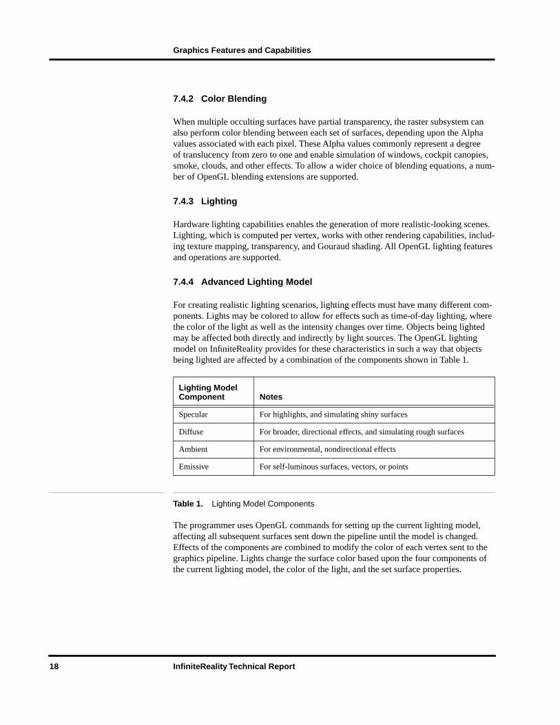
For creating realistic lighting scenarios, lighting effects must have many different com-ponents. Lights may be colored to allow for effects such as time-of-day lighting, where the color of the light as well as the intensity changes over time. Objects being lighted may be affected both directly and indirectly by light sources. The OpenGL lighting model on InfiniteReality provides for these characteristics in such a way that objects being lighted are affected by a combination of the components shown in Table 1.
The programmer uses OpenGL commands for setting up the current lighting model, affecting all subsequent surfaces sent down the pipeline until the model is changed. Effects of the components are combined to modify the color of each vertex sent to the graphics pipeline. Lights change the surface color based upon the four components of the current lighting model, the color of the light, and the set surface properties.
Lighting Model Component Notes
Specular For highlights, and simulating shiny surfaces
Diffuse For broader, directional effects, and simulating rough surfaces
Ambient For environmental, nondirectional effects
Emissive For self-luminous surfaces, vectors, or points
Table 1. Lighting Model Components
18 InfiniteReality Technical Report

Graphics Features and Capabilities
7.4.5 Surface Properties
In addition to the four lighting model components, a shininess component may be set for the current lighting model to handle different surface properties. This component may be changed from object to object to allow for a variety of different surface types in the environment. This property, in addition to light characteristics and surface color, may be combined with texture mapping and transparency to give you the maximum flexibility in defining surface reflectance characteristics.
7.4.6 Infinite Light Sources
Infinite light sources are assumed to be infinitely far from the surface they are illumi-nating; thus, light “rays” from these sources are assumed to arrive in parallel at all the surfaces affected.
7.4.7 Local Light Sources
Local light sources may exist close to the surface(s) they are illuminating; thus, the angle between the light source and the normals of the various affected surfaces can change dramatically from one surface to the next. Properties such as cutoff angle and attenuation may be specified for each light.
Since angles from surface normals to the light source must be computed every frame for each surface, local lights are far more computationally expensive than infinite lights and should be used judiciously in real-time applications.
7.5 Transparency
Each vertex to be rendered may have a transparency component, Alpha, along with the standard color components red, green, and blue. When Alpha is used to control the pixel color, objects of varying transparency/translucency may be included in a rendered scene. To insure that transparency is computed correctly and predictably, it is best to sort transparent objects from front to back with respect to the eyepoint, then draw these objects after all the nontransparent objects have been rendered.
7.6 Hidden Surface Removal
Current Silicon Graphics machines use a Z-buffering technique to remove hidden sur-faces. The Z (depth) buffer gives high-quality hidden surface removal during rendering without needing to sort the polygons. This process can thus be performed with few or no programming considerations in the software that traverses and renders the database.
Silicon Graphics floating-point Z-buffer technique for InfiniteReality is advancingthe state of the art by offering more uniform resolution across the Z dimension. InfiniteReality offers three options for Z-buffer precision: 23-bit, 16-bit compressed, and 15-bit compressed. The Z-buffer exists as dedicated memory in the frame buffer associated with each pixel. The first time a pixel is drawn, its Z-buffer value is set to the
InfiniteReality Technical Report 19

Graphics Features and Capabilities
Z of the primitive being drawn. Each time a subsequent attempt is made to set the color of that pixel because a new polygon is covering it, the system checks to see if that pixel’s Z-buffer value is further or closer than the Z value of the pixel being drawn. If the new pixel is closer, its color value replaces the previous value in the color buffer, and the Z-buffer is set to the new depth.
7.7 Anti-Aliasing
The high-performance anti-aliasing hardware of InfiniteReality continues the trend started with the RealityEngine2 graphics architecture. For the highest available image quality, memory and processors are put in the Raster Manager subsystem to give you multisampled anti-aliasing without the usual performance penalties. This anti-aliasing technique needs no data sorting and works with the Z-buffer for superior hidden surface removal.
Subpixel information is retained for all vertices in the pipeline as they are transformed and converted to raster primitives. Each primitive is computed with 8 x 8 subpixel accu-racy. Thus, there are 64 possible subpixel locations within each pixel rendered. When deciding how to color a pixel, the raster system samples each primitive at one, four, or eight of the subpixel locations in each pixel it touches. It then calculates color and depth information for the subpixels covered. This information is sent to the frame buffer where Z-buffering is performed on each subpixel, and a final color for each pixel is formed from the accumulated data from the set of subpixels within it.
In multisample anti-aliasing mode, Z information is kept for every subsample, giving hidden-surface accuracy down to the subpixel level. When transparency is used, the Alpha value is used to determine how much to blend the color of the closer pixel with the color of the farther pixel at that same location in the subpixel grid.
7.7.1 Sample Memory
The number of anti-aliasing samples available depends upon the total amount of frame buffer memory, the screen resolution, and the number of bits per image component desired.
20 InfiniteReality Technical Report

Graphics Features and Capabilities
Table 2 shows some of the possible memory configurations.
One RM Provides Sufficient Memory For:
1 960 x 680 display 8 samples 12 bits/component forRGBA
23-bit Z-buffer, 8-bit stencil
1 1280 x 1024 display 8 samples 10 bits/component forRGB
23-bit Z-buffer, 1-bit stencil
2 1280 x 1024 displays 4 samples 10 bits/component forRGBA
15-bit Z-buffer, 1-bit stencil
1 1920 x 1080 display 4 samples 10 bits/component forRGB
15-bit Z-buffer, 1-bit stencil
Two RMs Provide Sufficient Memory For:
1 1280 x 1024 display 8 samples 12 bits/component forRGBA
23-bit Z-buffer, 8-bit stencil
1 1600 x 1200 display or1 1920 x 1080 display
8 samples 10 bits/component forRGB
23-bit Z-buffer, 1-bit stencil
4 samples 12 bits/component forRGBA
23-bit Z-buffer, 1-bit stencil
2 1920 x 1080 display 4 samples 10 bits/component forRGB
15-bit Z-buffer, 1-bit stencil
Four RMs Provide Sufficient Memory For:
8 800 x 600 displays 8 samples 10 bits/component forRGB
23-bit Z-buffer,1-bit stencil
3 1280 x 1024 displays 8 samples 10 bits/component forRGB
23-bit Z-buffer, 1-bit stencil
2 1920 x 1080 displays 8 samples 10 bits/component forRGB
23-bit Z-buffer, 1-bit stencil
1 1920 x 1200 display 8 samples 12 bits/component forRGBA
23-bit Z-buffer8-bit stencil
Table 2. Anti-Aliasing Sample Memory Options
InfiniteReality Technical Report 21

Graphics Features and Capabilities
7.8 Texture/Image Mapping
Designed to display complex, texture-mapped scenes at real-time (60Hz) frame rates, InfiniteReality keeps compatibility with earlier RealityEngine2 and POWERVision™ systems, while dramatically improving performance and texture capacity and adding new features and functionality to texture mapping.
7.8.1 Texture Download
InfiniteReality downloads and draws textures simultaneously, allowing textures to be updated on-the-fly. Synchronization, built into the hardware and software, prevents tex-tures from being replaced until the system finishes with them and prevents a texture being drawn until it is completely loaded. The maximum texture download rate is 176 MB/sec from host memory or 240 MB/sec from frame buffer memory. See Table 3.
7.8.2 Texture Formats
InfiniteReality supports three basic texture element (texel) sizes: 16-bit, 32-bit, and 48-bit, including 16-bit monochrome. Each size can represent several formats:
16-bit textures:
• Dual 4-bit Luminance with 4-bit Alpha
• Quad 4-bit Luminance, Intensity, or Alpha
• Dual 8-bit Luminance, Intensity, or Alpha
• 8-bit Luminance with 8-bit Alpha
• 12-bit Luminance, Intensity, or Alpha
• 12-bit Luminance with 4-bit Alpha
• 5-bit (each) RGB with 1-bit Alpha
• 4-bit (each) RGBA
• 16-bit Luminance, Intensity, or Alpha
Source 16 bit 32 bit 48 bit
Host Memory 76 MT/sec 44 MT/sec 22 MT/sec
Frame Buffer Memory 71 MT/sec 74 MT/sec 40 MT/sec
Table 3. Texture Rate for 512 x 512 Texture
22 InfiniteReality Technical Report

Graphics Features and Capabilities
32-bit textures:
• 16-bit Luminance with 16-bit Alpha
• 12-bit Luminance with 12-bit Alpha
• 8-bit (each) RGBA
• 10-bit (each) RGB with 2-bit Alpha
48-bit textures:
• 12-bit (each) RGB
• 12-bit (each) RGBA
The variety of formats allows you to trade off image quality against storage size and rendering speed. 32-bit textures require twice the storage of 16-bit textures, while 48-bit textures require four-times the storage of 16-bit textures. Generally, 16-bit textures ren-der faster than 32-bit textures, and 32-bit textures render faster than 48-bit textures for a given filtering mode.
Where vast amounts of low-resolution texture is required, you can use the texture select feature. In this case four 4-bit textures or two 8-bit textures are packed into one 16-bit texture. You may select which of the four (or two) textures are used at any given time.
7.8.3 Texture Filtering
One of the most powerful features of the InfiniteReality architecture is found in the vari-ety of advanced two-dimensional and three-dimensional texture filtering techniques that are supported. This variety allows you to choose the most appropriate filtering technique for your application.
The filtering techniques comprise two different classes: MIPmapped and non-MIP-mapped. The term MIPmapping is derived from the Latin phrase, multum in parvo, which means “many things in a small space.” The MIPmapping process takes a texture (image) to be used in a scene and generates a series of pre-filtered, lower-resolution ver-sions of that texture. The appropriate level of the MIPmapped texture is then applied to a polygon as required by the scene. This allows the texture to be minified without alias-ing artifacts. Different MIPmapped filtering techniques are then available to calculate the transitions between different MIPmap levels and between different texels (texture elements) within a level. These filtering techniques include:
• Point sampled
• Linear interpolated
• Bilinear interpolated
• Trilinear interpolated
• Quadlinear interpolated (for 3D textures)
Non-MIPmapped textures require filtering only among the different texels within the texture map. These filtering techniques include
InfiniteReality Technical Report 23

Graphics Features and Capabilities
• Point sampled (for 2D or 3D textures)
• Bilinear interpolated (for 2D textures)
• Trilinear interpolated (for 3D textures)
• Bicubic interpolated (for 2D textures)
InfiniteReality is designed to provide all of the filtering techniques listed above at full texture processing performance levels, except for quadlinear interpolated MIPmapping and bicubic interpolated filtering which operate at half the rate of the others. It is impor-tant to recognize that trilinear interpolated non-MIPmapped 3D texture filtering is avail-able at full texture processing performance levels. This represents a significant perfor-mance improvement compared to RealityEngine2, which processed this filtering tech-nique at one-half the peak performance level of other RealityEngine2 texture filters.
7.8.4 Global Texturing
An important and innovative new feature of InfiniteReality is Global Texturing. Global texturing accelerates processing of terrain data mapped with satellite and aerial photo-graphs. In RealityEngine2, traditional MIPmapping techniques were used to apply aerial photographs to terrain meshes. Large geographic areas were covered by tiling a number of smaller MIPmaps together across the terrain area. This technique, though powerful, required a large number of textures and a significant amount of texture memory. Unused texture tiles were stored in main memory and downloaded into the RealityEngine2 tex-ture buffer when required. In this case, textures were either stored in system memory or texture memory, but they could not be split between the two.
In InfiniteReality, global texturing allows you to define a single MIPmap that is much larger than that which can be stored in texture memory. Only the parts of the MIPmap that are actually used in rendering an image are stored in texture memory; the rest is stored in main memory or on disk. As the point of view moves, the portion of the MIP-map that is stored in memory is updated to reflect the new point of view.
7.8.5 Modulation and Decals
Each texture can be treated in two ways when applied to a polygon. When operating as a decal, the color of the texture replaces inherent color to the polygon. During modula-tion, the texture color is blended with the color and surface properties and thus looks different on various surfaces.
7.8.6 Texture/Image Memory
Each RM can have either 16MB or 64MB of texture memory. For non-MIPmapped tex-tures this means that the texture memory can hold 8 million or 32 million 16-bit texels respectively. MIPmapped textures require extra storage for the prefiltered lower levels of detail, amounting to one-third the size of the finest level of detail.
24 InfiniteReality Technical Report
Graphics Features and Capabilities
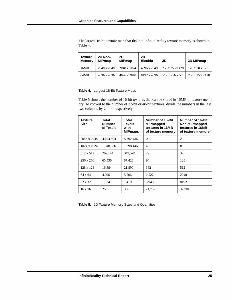
The largest 16-bit texture map that fits into InfiniteReality texture memory is shown in Table 4:
Table 5 shows the number of 16-bit textures that can be stored in 16MB of texture mem-ory. To convert to the number of 32-bit or 48-bit textures, divide the numbers in the last two columns by 2 or 4, respectively.
Texture Memory
2D Non-MIPmap
2D MIPmap
2D Bicubic 3D 3D MIPmap
16MB 2048 x 2048 2048 x 1024 4096 x 2048 256 x 256 x 128 128 x 28 x 128
64MB 4096 x 4096 4096 x 2048 8192 x 4096 512 x 256 x 56 256 x 256 x 128
Table 4. Largest 16-Bit Texture Maps
Texture Size
Total Number of Texels
Total Texels with MIPmaps
Number of 16-Bit MIPmapped textures in 16MB of texture memory
Number of 16-Bit Non-MIPmapped textures in 16MB of texture memory
2048 x 2048 4,194,304 5,592,436 0 2
1024 x 1024 1,048,576 1,398,146 4 8
512 x 512 262,144 349,570 22 32
256 x 256 65,536 87,426 94 128
128 x 128 16,384 21,890 382 512
64 x 64 4,096 5,506 1,522 2048
32 x 32 1,024 1,410 5,948 8192
16 x 16 256 386 21,732 32,784
Table 5. 2D Texture Memory Sizes and Quantities
InfiniteReality Technical Report 25

Graphics Features and Capabilities
Table 6 lists the same information for 3D textures.
7.8.7 Texture Transparency and Contouring
Textures may have full or partial transparency set at any texel location. If the entire outer edge of the uniquely shaped texture, such as a tree, is set to transparent, the texture may be placed upon a rectangular polygon and still appear to have the outline of a tree.
7.8.8 Perspective Correction
The raster subsystem performs per-pixel computations to correct textures and fog for perspective distortions to insure that no artifacts are put into the rendering process. These computations do not affect system performance.
7.8.9 Detail Texture
Detail texture increases the effectiveness of motion and position cues by providing addi-tional detail on top of the existing texture as the textured surface draws nearer to the eyepoint. Detail texture lets high-resolution textures be represented with a small high-frequency characteristic texture and a lower resolution-base texture. The high-frequency detail is smoothly combined with the base texture to give much of the visual qualities of the original texture, while using a fraction of the texture memory.
7.8.10 Sharp Texture
Textures enable creation of highly realistic scenes, largely due to the ability to import photographic images, which can be applied to geometry. The resolution of these images is finite, however. When they are enlarged to the point where the textured polygon is larger than the original texture resolution, magnification tends to blur the original image.
The solution is the patented Sharp Texture feature in the InfiniteReality subsystem, which lets you specify that edges remain sharp during magnification. For example, this enables the development of a simulation whose photo-derived sign textures would con-tinue to be readable as they get close to the eyepoint of the viewer.
Texture Memory Resolution Number
16MB 128 x 128 x 128 4 (non-MIPmapped)
16MB 128 x 128 x 128 2 (MIPmapped)
64MB 128 x 128 x 128 16 (non-MIPmapped)
64MB 128 x 128 x 128 14 (MIPmapped)
Table 6. 3D Texture Sizes for 16-Bit Textures
26 InfiniteReality Technical Report
Graphics Features and Capabilities
7.8.11 Projective Texture
With Projective Texture, textures can be projected into a scene, bending over every sur-face. This allows for sophisticated spotlighting effects, such as landing lights, and pro-jection of camera data onto synthetic terrain.
7.8.12 Shadow Maps
InfiniteReality provides hardware support for shadowing. Applying shadows is a two- step process: the scene of interest is first rendered from the light source point of view; the depth information from the scene is then copied into texture memory. The result is a shadow map. The scene is then rendered from the eyepoint. Hardware determines which parts of the scene are in shadow and which are not, based on the shadow map, and lights them accordingly. The approach can be extended to multiple light sources by rendering in multiple passes.
7.8.13 Billboards
Billboards are textured faces that automatically track the eyepoint so that they are always facing the viewer. A common application is for trees in a database.
7.8.14 Detail Management
You can restrict which MIPmap levels of detail are used. This allows use of a partially loaded MIPmap. If a MIPmap is loaded starting at the coarsest level, the texture can be used before its finest levels of detail have been loaded.
7.8.15 Video to Texture
Using the Sirius Video option, live video can be loaded in real time directly into texture memory from a video source. This permits you to map broadcast-quality video directly onto any three-dimensional (3D) surface and concurrently perform image processing functions on the video stream.
7.8.16 3D Textures and Volume Rendering
InfiniteReality includes the advanced 3D texture feature, which enables real-time 3D volume rendering. An example of this is viewing a series of two-dimensional medical scans of a patient’s head.
InfiniteReality has the power to reconstruct the series of two-dimensional scans into a three-dimensional volume. The volume can be manipulated (rotated, translated, filtered, and more) in real time by continuously resampling (interpolating) the data in 3D. Vol-ume rendering can be enhanced by using the following features:
• Slicing planes
• Perspective projection
• Embedded surfaces
InfiniteReality Technical Report 27
Graphics Features and Capabilities
For more information, see Fraser, Robert, “Interactive Volume Rendering Using Advanced Graphics Architectures,” Silicon Graphics Computer Systems.
7.9 Imaging Operations
As in RealityEngine2, the Geometry Engine processors of InfiniteReality provide hard-ware accelerated imaging operations, including convolution, minmax, histogram, color matrix, and lookup tables. Because all pixel processing paths, including drawing, copy-ing, and reading of pixels, texels, and video data, flow through the Geometry Engine processors, these image operators can be applied between any source and destination. For example, an application may copy pixels from a video source to texture memory and perform color space conversion using the color matrix in one pixel transfer operation.
7.9.1 Convolution
The convolution operator filters linear images in real time. The user-definable filter per-forms operations such as sharpening and blurring. InfiniteReality supports separable and general convolution filters of size 3 x 3, 5 x 5 and 7 x 7. Separable filters are much faster than general filters. Likewise, smaller filters are faster than larger filters. Applications can trade off quality and throughput by choosing an appropriate filter size and type.
7.9.2 Histogram and Minmax
Histograms and minmax provide statistics on color component values within an image. A histogram counts occurrences of specific color component values and reports them in user-defined bins with up to 4,096 bins per component. Minmax tracks minimum and maximum color component values. These statistics can be analyzed to create a more balanced, better-quality image.
7.9.3 Color Matrix and Linear Color Space Conversion
The color matrix operation transforms the colors of each pixel by a user-defined 4 x 4 matrix. In addition to performing linear color space conversion, the color matrix can also be used to perform color component swapping and component replication.
7.9.4 Window/Level Support
Remote sensing, medical imaging, and film editing applications can process data with a greater dynamic range than a video monitor can display. The window/level operation allows a subset of the data’s full dynamic range to be selected (windowed) and its con-trast and brightness adjusted (leveled) so that important image features will be seen on a monitor.
The frame buffer and imaging data path of InfiniteReality support display and texturing using 16-bit luminance data, good for demanding high-precision imaging applications. The 32K-entry color lookup table on the DG4 board enables real-time window/level operations on multiple windows over 12-bit subranges without requiring images to be redrawn.
28 InfiniteReality Technical Report

Graphics Features and Capabilities
7.9.5 Lookup Tables (LUTs)
Color tables can be inserted in various stages of the pixel path to adjust image contrast and brightness after an image operation. Each color table can have up to 4,096 entries per color component and can be loaded directly from host or frame buffer memory.
7.10 Atmospheric Effects
A programmable fog/haze function in InfiniteReality allows you to set an arbitrary fog color that can be blended with the color of any element to be rendered. You can change the fog for all or part of the scene on a per-channel or per-object basis. The amount of fog or haze color you use depends on the depth value of each pixel of each selected object.
You can specify the falloff function and the density of the fog. InfiniteReality also allows you to specify a fog function using sample points.
Compared to RealityEngine2, the precision and the smoothness of fog/haze appearance in InfiniteReality is greatly improved. Based on the viewing projection, depth range, and the fog function itself, the system automatically optimizes generation of per-pixel fog values. Each fog value generated has 12-bits of precision per color component.
7.11 Offscreen Rendering
InfiniteReality systems have abundant frame buffer memory–80MB on each Raster Manager board—used to store pixels for very-high-resolution displays, or for multiple video output channels. It also may be used to store pixels for offscreen rendering.
A frame buffer pixel contains from 256 to 1,024 bits, depending upon the system’s Raster Manager board quantity and video output channel characteristics. Some bits are dedicated to front and back color buffers (when applications use double buffering), the depth (Z) buffer, and other buffers supported by OpenGL (see Figure 4).
InfiniteReality Technical Report 29

Graphics Features and Capabilities
Figure 4. Frame Buffer Pixel Memory
Remaining memory is available for other uses. Applications may invoke the SGIX_fbconfig OpenGL extension to choose a frame buffer configuration for unas-signed memory (see Figure 5).
Figure 5. Frame Buffer Pixel Memory Including Offscreen Buffers
OverlaysColor
DepthAvailable space
Window
Pixel
Buffers
OverlaysColor
DepthColor
Depth
Pixel
Window
Offscreen
Buffers
Buffers
30 InfiniteReality Technical Report

Graphics Features and Capabilities
After selecting a frame buffer configuration, applications may invoke the SGIX_PBuffer OpenGL extension to create an offscreen rendering area called a PBuffer (Pixel Buffer). PBuffers occupy part of the frame buffer not otherwise occupied by ordinary windows (see Figure 6).
Figure 6. Disjoint Buffers and PBuffers
PBuffers are much like windows; OpenGL applications may render into PBuffers just as they render into windows. However, PBuffers never obscure color buffers of windows and are never displayed on any video output channel.
PBuffers may serve as a cache for frequently accessed images, improving performance dramatically by removing the need to transfer pixels from host memory to the graphics pipeline. They may be used for storing results of special-purpose renderings that are not intended for display, such as shadow maps. PBuffers are also convenient repositories for the intermediate results of multipass rendering algorithms, which produce effects such as reflections, Phong shading, and bump mapping. Finally, PBuffers permit InfiniteReality to accelerate background batch processing of long-running imaging operations without disabling interactive use of the main display.
7.12 Multi-Channel Display Generator
The display generator feature takes digital, ordered pixel output from the frame buffer and lets you specify from two to eight separate rectangular areas to be sent from the rectangular frame buffer area managed by the x-server to independent component RGB video outputs. Each video channel may have its own video timing, increasing flexibility over previous products.
PBuffer
Window
Frame Buffer
InfiniteReality Technical Report 31

Graphics Features and Capabilities
7.12.1 Standard Formats and Format Combinations
To provide you with as much built-in flexibility as possible, InfiniteReality systems are delivered with a broad range of software-selectable video formats and format combina-tions, from NTSC to 1920 x 1080 progressive-scan HDTV. Tables 7 and 8 show InfiniteReality formats shipped standard with the system.
Video Format Video Format File Notes
640 x 480 120Hz stereo 640 x 480_120s.vfo
640 x 480 180Hzfield sequential stereo
640 x 480_180q.vfo Color field sequential 180Hzformat
640 x 480 60Hz 640 x 480_60.vfo VGA
640 x 486 30Hz interlaced 640 x 486_30i.vfo
646 x 486 30Hz interlaced 646 x 486_30i.vfo Frame locking format
646 x 486 30Hz interlaced 646 x 486_30if.vfo NTSC
768 x 576 25Hz interlaced 768 x 576_25i.vfo PAL
768 x 576 25Hz interlaced 768 x 576_25if.vfo Frame locking format
770 x 576 25Hz interlaced 770 x 576_25i.vfo
800 x 600 60Hz 800 x 600_60.vfo SVGA
960 x 620 60Hz 960 x 620_60.vfo
960 x 680 60Hz 960 x 680_60.vfo
1024 x 768 120Hz stereo 1024 x 768_120s.vfo
1024 x 768 60Hz 1024 x 768_60.vfo
1024 x 768 96Hz stereo 1024 x 768_96s.vfo
1080 x 809 30Hz interlaced 1080 x 809_30i.vfo RS343-A “875-line” format
1120 x 840 96Hz stereo 1120 x 840_96s.vfo
1200 x 900 72Hz 1200 x 900_72.vfo High-resolution 4:3 format
1280 x 1024 114Hz stereo 1280 x 1024_114s.vfo
1280 x 1024 120Hz stereo 1280 x 1024_120s.vfo
1280 x 1024 25Hz PAL 1280 x 1024_25f.vfo Frame locking format
1280 x 1024 25Hz PAL 1280 x 1024_25r2.vfo Special format
1280 x 1024 25Hz PAL 1280 x 1024_25r3.vfo Special format
1280 x 1024 30Hz NTSC 1280 x 1024_30f.vfo Frame locking format
continued on page 33
32 InfiniteReality Technical Report

Graphics Features and Capabilities
Table 7. Standard Formats Shipped with All InfiniteReality Systems
1280 x 1024 30Hz NTSC 1280 x 1024_30r2.vfo Special format
1280 x 1024 50Hz 1280 x 1024_50.vfo
1280 x 1024 50Hz PAL 1280 x 1024_50f.vfo Frame locking format
1280 x 1024 60Hz 1280 x 1024_60.vfo High-resolution
1280 x 1024 60Hz 1280 x 1024_60f.vfo Frame locking format
1280 x 1024 72Hz 1280 x 1024_72.vfo
1280 x 959 30Hz interlaced 1280 x 959_30i.vfo
1500 x 1200 60Hz 1500 x 1200_60.vfo
1600 x 1200 60Hz 1600 x 1200_60.vfo Extra-high-resolution
1760 x 1100 60Hz 1760 x 1100_60.vfo
1920 x 1035 30Hz interlaced 1920 x 1035_30i.vfo Japan HDTV
1920 x 1080 72Hz 1920 x 1080_72.vfo US HDTV
1920 x 1152 25Hz interlaced 1920 x 1152_25i.vfo Euro HDTV
1920 x 1200 66Hz 1920 x 1200_66.vfo New ultra-high-resolution
1920 x 1200 75Hz 1920 x 1200_75.vfo
CCIR601_525 CCIR601_525.vfo
CCIR601_625 CCIR601_625.vfo
Standard Combinations Combiner File
1 1280 x 1024 60Hz 1280 x 1024_60.cmb
1 1280 x 1024 72Hz 1280 x 1024_72.cmb
1 960 x 680 60Hz 960 x 680_60.cmb
1 1024 x 768 60Hz 1024 x 768_60.cmb
1 1120 x 840 96Hz 1120 x 840_96s.cmb
1 1200 x 900 72Hz 1200 x 900_72.cmb
1 1600 x 1200 60Hz 1600 x 1200_60.cmb
Video Format Video Format File Notes
continued on page 34
continued from page 32
InfiniteReality Technical Report 33
Graphics Features and Capabilities
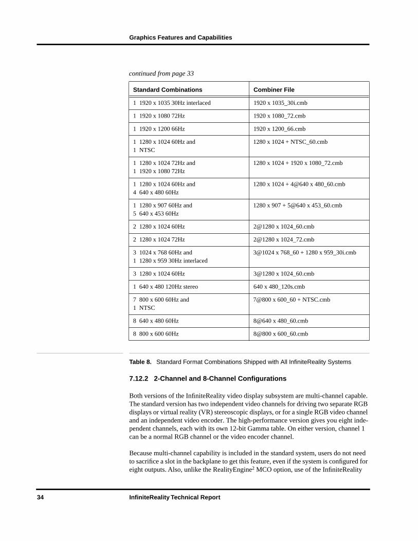
continued from page 33
Table 8. Standard Format Combinations Shipped with All InfiniteReality Systems
7.12.2 2-Channel and 8-Channel Configurations
Both versions of the InfiniteReality video display subsystem are multi-channel capable. The standard version has two independent video channels for driving two separate RGB displays or virtual reality (VR) stereoscopic displays, or for a single RGB video channel and an independent video encoder. The high-performance version gives you eight inde-pendent channels, each with its own 12-bit Gamma table. On either version, channel 1 can be a normal RGB channel or the video encoder channel.
Because multi-channel capability is included in the standard system, users do not need to sacrifice a slot in the backplane to get this feature, even if the system is configured for eight outputs. Also, unlike the RealityEngine2 MCO option, use of the InfiniteReality
1 1920 x 1035 30Hz interlaced 1920 x 1035_30i.cmb
1 1920 x 1080 72Hz 1920 x 1080_72.cmb
1 1920 x 1200 66Hz 1920 x 1200_66.cmb
1 1280 x 1024 60Hz and1 NTSC
1280 x 1024 + NTSC_60.cmb
1 1280 x 1024 72Hz and1 1920 x 1080 72Hz
1280 x 1024 + 1920 x 1080_72.cmb
1 1280 x 1024 60Hz and4 640 x 480 60Hz
1280 x 1024 + 4@640 x 480_60.cmb
1 1280 x 907 60Hz and5 640 x 453 60Hz
1280 x 907 + 5@640 x 453_60.cmb
2 1280 x 1024 60Hz 2@1280 x 1024_60.cmb
2 1280 x 1024 72Hz 2@1280 x 1024_72.cmb
3 1024 x 768 60Hz and1 1280 x 959 30Hz interlaced
3@1024 x 768_60 + 1280 x 959_30i.cmb
3 1280 x 1024 60Hz 3@1280 x 1024_60.cmb
1 640 x 480 120Hz stereo 640 x 480_120s.cmb
7 800 x 600 60Hz and1 NTSC
7@800 x 600_60 + NTSC.cmb
8 640 x 480 60Hz 8@640 x 480_60.cmb
8 800 x 600 60Hz 8@800 x 600_60.cmb
Standard Combinations Combiner File
34 InfiniteReality Technical Report
Graphics Features and Capabilities
multi-channel feature does not disturb or disable operation of the ‘main’ video output channels. All additional channels are as easy to program as the main channel; the same video format compiler works for all.
7.12.3 InfiniteReality Multi-Channel Features: Considerations
Several system resources must be considered in multi-channel applications: frame buffer memory, frame buffer read/write bandwidth, DAC bandwidth, and frame buffer-to-video subsystem transmission bandwidth.
7.12.3.1 Swap Rates Must Be Equal
Video formats that run together in a video combination must provide time for “house-keeping” operations such as updating cursor position and glyph, setting parameters for dynamic pixel resampling, and more. This may be done at field boundaries, frame boundaries, or in certain cases, across multiple frames. This interval is defined by the “maximum swap rate.” This rate must be the same for all video formats running together, so that the InfiniteReality video display subsystem can simultaneously perform these housekeeping services for all running video formats.
For example, a legal combination of formats would be the following:
• 30Hz interlaced NTSC (swap rate is the 60Hz field rate for this format)
• 60Hz non-interlaced 1280 x 1024
• 120Hz stereo (swap rate is the 60Hz frame rate)
• 180Hz color field sequential (again, the swap rate is the 60Hz frame rate)
Examples of illegal combinations would be NTSC (60Hz swap rate) and PAL (50Hz swap rate), or 60Hz and 72Hz versions of 1280 x 1024. In these cases, the swap rates are not the same.
“Equal” is a relative term. For example, NTSC, which really runs at 59.94Hz field rates, is “close enough” to be run with 60Hz 1280 x 1024. In general, if the swap rates are close enough to allow the video formats to be reliably synchronized to one another, they are considered “equal.” This tolerance is usually less than 0.2 percent.
7.12.3.2 Frame Buffer-to-Video Display Subsystem Transmission Bandwidth
Digital video data is sent serially from the InfiniteReality frame buffer to the video sub-system. Each video channel uses a portion of the system’s aggregate video transmission bandwidth. The required bandwidth per channel depends on the resolution of the video output format running on that channel and on the type of video it receives from the frame buffer. The requirements of all video channels must be less than the aggregate video bandwidth of the system.
Depending on the number and precision of color components requested from the frame buffer by each video channel, the available video transmission bandwidth ranges from approximately 290M pixels/sec (for 10-bit RGB or 12-bit color field-sequential video) to 210M pixels/sec (for 10-bit RGBA or 12-bit RGB video). The digital data stream
InfiniteReality Technical Report 35

Graphics Features and Capabilities
from the frame buffer to a particular video channel must be of a single type and preci-sion, for example, 10-bit RGB. However, different video channels (and associated digi-tal video streams from the frame buffer) may be mixed: one channel may request 10-bit RGB, while another channel may request 12-bit RGB, and yet another channel may request 10-bit RGBA. Depending on the mix of currently running video formats, the total required video transmission bandwidth will fall between approximately 210M and 290M pixels/sec.
Distinguishing the transmission format for video from the “depth” of pixels in the frame buffer is important. Pixel depth (“small,” “medium,” “large,” “extra-large”) must be uni-form across the entire managed area of the frame buffer. As stated above, the format of the colors transmitted as video from a frame buffer to the video display subsystem may vary on a per-channel basis to conserve aggregate video transmission bandwidth. Frame buffer memory stores non-video information about each pixel (such as multisample and Z information); the color fields are a subset of the frame buffer pixel storage. Distin-guishing between frame buffer representation of pixels and the format chosen for video transmission to the video display subsystem is important, if you want to understand and optimize the performance of both the frame buffer memory and video display sub-system.
The total frame buffer-to-video-subsystem bandwidth is independent of the number of Raster Manager boards in the system.
7.12.3.3 DAC Output Bandwidth
When configuring a video format combination, you must decide which format to assign to which video channel. The first two video channels have DACs with a 220M pixel/sec bandwidth limit. The remaining six channels have a 170M pixel/sec bandwidth limit. Because each channel can do dynamic resampling, actual video resolution as output by the DAC (and seen by the display monitor connected to the channel) may be higher than the resolution of the rectangular region of the frame buffer assigned to that channel. The highest-bandwidth video formats of a video format combination should always be assigned to channels 0 and 1.
7.12.3.4 Frame Buffer Memory
Another requirement for video format combinations is that they must all be able to tile rectangular subregions of a rectangular frame buffer. Depending upon the “depth” of pixels selected and the number of Raster Manager boards installed, some combinations of formats may require more than one Raster Manager board. When selecting frame buffer pixel depth you must consider the quality of multisampling, the precision of the Z-buffer and RGB colors stored in the frame buffer, and total system fill-rate capability.
Adding RM boards does not increase total frame buffer to video subsystem bandwidth, but it increases the total drawing fill-rate available, and amortizes the video refresh over-head over more RM boards, leaving more fill-capacity available for drawing.
36 InfiniteReality Technical Report

Graphics Features and Capabilities
7.12.3.5 Frame Buffer Read/Write Bandwidth
A final consideration for video format combinations is the overhead that refreshing video channels presents to the frame buffer. The greater the number and resolution of video channels, the more the pixel fill-rate of the system is reduced. A particular combi-nation of formats may fit into a 1-RM or 2-RM configuration, but it may unacceptably reduce the fill rate.
7.12.4 Video Format Combiner Tool
To make the necessary tradeoffs between these requirements, the system includes the Video Format Combiner software tool. This tool has a command-line interface and a graphical user interface (GUI). Using the GUI form, it can easily see which regions of the frame buffer are mapped to which channels. Pixel bandwidth and fill-rate overhead due to video are dynamically displayed. When system limits are exceeded, the tools attempt to provide hints about what remedial action to take.
If system resources of a target hardware configuration are sufficient enough to support a group of video formats, the combiner tool creates a combination file with filename ref-erences to the video formats and information about configuring the video hardware to run that channel combination.
Only video format combinations ‘approved’ by the video format combiner are allowed to be loaded into the video subsystem (even if only a single channel is enabled). This is done with the video format combiner itself or with the familiar setmon program. In addition, there is a programming interface provided by an X-Windows™ server exten-sion, XSGIvc, for application developers who want to integrate video control into their applications.
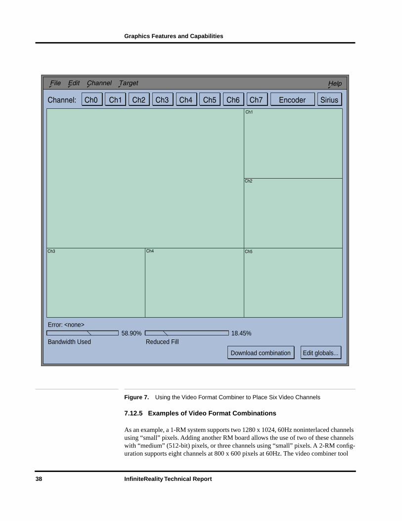
Figure 7 shows an example of using the video format combiner tool interactively to place six video channels on a 1-RM InfiniteReality system in a managed area of 1920 x 1360 pixels. “Small” (256-bit) pixels are used. Channel 0 is a 1280 x 1024 video format mapped to a 1280 x 907 region of the frame buffer using static resizing. Chan-nels 1 through 4 are in a 640 x 480 video format. Using static resizing, each is mapped to a 640 x 453 region of the frame buffer.
This example illustrates the use of video resizing to efficiently use the frame buffer. If static resizing were not used, only four 640 x 480 channels would fit in addition to the 1280 x 1024 channel. Note indicators at the bottom of the screen that show this video format combination is using 58.90 percent of the available pixel transmission band-width, and that the fill capability of this combination is reduced by 18.45 percent. For comparison, a single 1280 x 1024 screen would reduce the fill rate of a 1-RM system by about 10 percent. In other words, when running this combination, 81.55 percent (100 percent – 18.45 percent) of the fill rate is available for drawing into the frame buffer.
InfiniteReality Technical Report 37
Graphics Features and Capabilities
Figure 7. Using the Video Format Combiner to Place Six Video Channels
7.12.5 Examples of Video Format Combinations
As an example, a 1-RM system supports two 1280 x 1024, 60Hz noninterlaced channels using “small” pixels. Adding another RM board allows the use of two of these channels with “medium” (512-bit) pixels, or three channels using “small” pixels. A 2-RM config-uration supports eight channels at 800 x 600 pixels at 60Hz. The video combiner tool
Error: <none>
Bandwidth Used Reduced Fill58.90% 18.45%
Download combination Edit globals...
38 InfiniteReality Technical Report

Graphics Features and Capabilities
allows these kinds of “what if” scenarios to be explored, enabling users to easily config-ure the InfiniteReality graphics system for their particular application. Table 9 shows several example configurations. Many others are possible.
7.12.6 Dynamic Resolution
InfiniteReality incorporates on-the-fly video resampling on all its video channels. This feature is “Dynamic Resolution”. Dynamic resolution works on all video formats with pixel rates of 120MHz or less.
(Note: This restriction eliminates only the highest-resolution formats.)
This feature provides several benefits:
• Dynamic Resolution, available through IRIS Performer™ as well as OpenGL, gives you a powerful new method of guaranteeing scene update rates. This method works in addition to geometric level-of-detail methods.
• The video encoder channel can now encompass an entire video channel, allowing whole-screen recording without an external scan-converter. For video formats with pixel clock rates above 120MHz, the encoder works in “pass-through” mode similar to RealityEngine2, allowing recording of a pannable NTSC or PAL-sized region of the display.
• Dynamic resampling of a frame buffer region allows a smaller frame buffer region to be “zoomed” or enlarged to fit the video format resolution of the video channel assigned to that frame buffer region. This aids efficient use of frame buffer memory without requiring non-standard video formats.
Video Format Combinations Notes
2 @ 1280 x 1024, 60Hz Uses all memory on 1-RM (“small” frame buffer pixels)
3 @ 1280 x 1024, 72Hz Uses nearly the entire available pixel bandwidth. Requires2-RMs for sufficient memory (“small”pixels)
8 @ 800 x 600, 60Hz Uses all channels. Needs 2-RMs for sufficient memory(“small” pixels)
7 @ 800 x 600, 60Hz +NTSC Encoder
Uses all channels. Channel 1 is used by Composite VideoEncoder when enabled.
3 @ 1024 x 768, 60Hz +RS343-A 1260 x 945, 30Hzinterlaced
Not all formats need the same resolution. Field rates of allvideo formats must match. Requires 2-RMs for sufficientmemory (“small” pixels)
1 @ 1920 x 1080 +1 @ 1280 x 1024 both at 72Hz
1920 x 1080 channel must be assigned to high-speed DAC(channel 0 or channel 1). Requires 2-RMs for sufficientmemory (“small” pixels)
Table 9. Examples of Video Format Combinations
InfiniteReality Technical Report 39

Graphics Features and Capabilities
7.12.7 Stereoscopic Video Output
InfiniteReality continues the RealityEngine2 style of support for stereoscopic viewing in a window. Individual windows may be run in stereoscopic viewing mode, displaying a separate left-eye view and right-eye view each 120th of a second. All other windows and pop-ups appear normal.
7.12.8 Direct Support of Color Field Sequential Video
InfiniteReality provides direct, efficient support of time-multiplexed, sequential color field video, commonly known as color field-sequential video. Cursors and color index pop-up regions appear in their true colors, making it easy to integrate applications using color field-sequential video with the X-Windows environment.
7.12.9 Luminance
Luminance (monochrome rendering) is supported by the video display subsystem. Applications may select luminance to be displayed as color mapped pseudo-color or as static-gray X-visual. Ultra-high color resolution (16 bits) is supported for rendering operations such as texture (but not lighting) using luminance.
7.12.10 Programmable Video Timing
InfiniteReality advanced circuitry generates a programmable pixel clock to enable the broadest range of applications, from video production to visual simulation. The clock controls the rate at which the frame buffer is scanned out to a video signal. The standard system supports 1920 x 1200 pixels at 66Hz non-interlaced.
Some applications need different video timing, such as military displays requiring the RS-343 standard, or stereoscopy for molecular modeling, which requires 120Hz video field rate to output a left-eye view and a right-eye view at 60Hz each. InfiniteReality programmable video timing supports these and other video formats. By introducing the InfiniteReality Video Format Compiler, InfiniteReality puts video format programming capability in your hands.
Video formats produced by the Video Format Compiler must be put into a video format combination using the Video Format Combiner tool (Section 7.12.4) to validate that they will operate correctly on the InfiniteReality video display subsystem hardware. In the case of a single format, the word “combination” is a misnomer; the key concept is that all video formats, whether running alone or in combination with other video for-mats, must be validated by the video combiner to ensure that the video format is com-patible with the display hardware.
40 InfiniteReality Technical Report

Graphics Features and Capabilities
7.13 Genlock
To ensure that InfiniteReality graphics subsystems video output is synchronized with other video sources or pipelines, the system includes a standard external genlock capa-bility. Genlock assures that multiple video sources all start scanning out their frames at the same time for frame-synchronized multi-channel output.
Video channels in video subsystems of InfiniteReality are automatically frame-synchronized, whether they are of the same resolution, and regardless of whether the external genlock feature is enabled. External genlock capability lets the master video format (the format running on the lowest-numbered video channel) genlock to an exter-nal video source.
Unlike previous systems, the external video source only needs the same vertical sync rate as the master format; it does not need the identical format running on the master channel. This provides maximum flexibility in synchronizing to multiple InfiniteReality graphics pipelines, or to video equipment of other vendors.
There are three methods of frame synchronization:
• Genlock
• Frame-lock
• Frame-reset
The best of these is genlock. It is used when two video formats are the same resolution and frame rate. The internal circuitry is able to make adjustments every horizontal period to insure that the system is locked.
The next-best method is frame-lock which is similar to genlock. But adjustments are made at intervals corresponding to the least-common multiple of the two dissimilar hor-izontal rates in the two video formats because of differences in format resolution.
If the least-common multiple period is too great, the system uses the frame-reset method of synchronizing frames. In the frame-reset method, the system merely issues a reset signal to the timing circuitry of the system to be synchronized. This method may allow frames to be “dropped” occasionally. Genlock and frame-lock guarantee that frames will not be dropped or missed.
The video combiner tool will select the best-quality frame synchronizing method, based on the video formats in the combination file, and the video format selected for external genlocking.
7.13.1 Video Options
In addition to the standard display options available from the InfiniteReality display subsystem, the Sirius Video option board is available for functions such as real-time, broadcast-quality video image capture and recording.
InfiniteReality Technical Report 41
Graphics Features and Capabilities
7.13.2 Video Input
Sirius Video serves applications needing live video input. Sirius Video gives you two inputs, which can be blended using incoming alpha key, internal chroma key generation, or a key generated in real time from InfiniteReality graphics.
7.14 Sirius Video Option
Sirius Video provides real-time video input to the InfiniteReality graphics system through a proprietary interconnect, or to the POWERchannel-2 system bus through the industry-standard VME interface. Thus, live video can be routed to InfiniteReality tex-ture memory at full video frame rates, giving you live video textures onto 3D geometry. This enables a new class of 3D digital video effects as well as giving you tight integra-tion between graphics and video. In addition, Sirius Video gives you video input and output interface from disk and memory subsystems (via VME). An equipped Onyx, POWER Onyx, CHALLENGE, or POWER CHALLENGE can therefore read and write real-time uncompressed video to and from disk or memory.
Sirius Video supports real-time output of CCIR601 (parallel is standard, serial 601 is an option), 4:4:4:4 digital video, YUVA, RGBA, Composite, and S-Video formats in 8-bit and 10-bit resolutions. It also provides both V-LAN and GPIB for machine control, as well as blending, color space conversion, and chroma keying. As with video channels on InfiniteReality, full-screen scan-conversion is supported on the Sirius Video channel.
Applications requiring live video input are served by the Sirius Video option. Sirius Video gives you two inputs which can be blended using incoming alpha key, internal chroma key generation, or by using a key generated in real time from InfiniteReality graphics.
7.15 Integration with X Window System
InfiniteReality graphics are integrated with the X Window System™, giving multiple, independent graphics displays from a single frame buffer. The X11 standard is fully sup-ported, and native OpenGL is integrated without degradation of graphics pipeline per-formance when drawing into windows (versus a dedicated full screen).
InfiniteReality also unites a number of unique capabilities with respect to X Window System support. Up to 16 windows can have their own 12-bit color look-up-tables (LUTs) to provide a stable, independent data space that does not require reloading with each current window switch.
42 InfiniteReality Technical Report