1 UNIT 1 Foundation Computer Networks: A Systems Approach, 5e Larry L. Peterson and Bruce S. Davie...
160
1 UNIT 1 Foundation Computer Networks: A Systems Approach, 5 Larry L. Peterson and Bruce S. Davie Copyright © 2010, Elsevier Inc. All rights Reserved
-
Upload
nickolas-robbins -
Category
Documents
-
view
235 -
download
2
Transcript of 1 UNIT 1 Foundation Computer Networks: A Systems Approach, 5e Larry L. Peterson and Bruce S. Davie...
1
UNIT 1
Foundation
Computer Networks: A Systems Approach, 5eLarry L. Peterson and Bruce S. Davie
Copyright © 2010, Elsevier Inc. All rights Reserved
2
Chapter 1
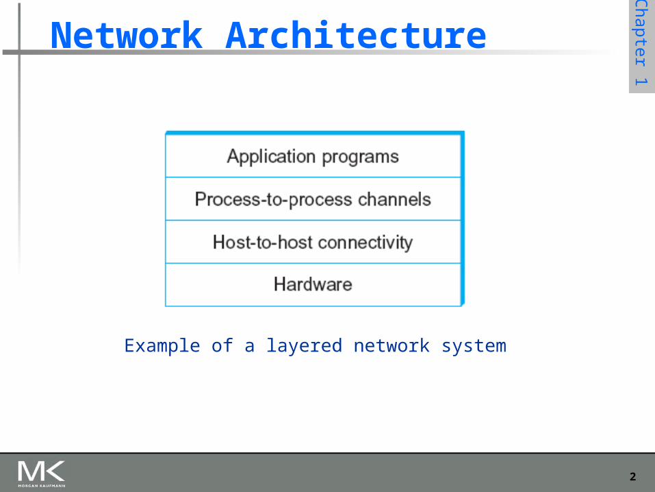
Network Architecture
Example of a layered network system
3
Chapter 1
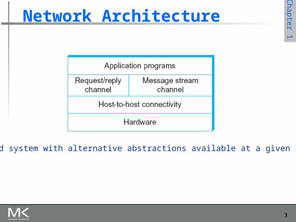
Network Architecture
Layered system with alternative abstractions available at a given layer
4
Chapter 1
Protocols
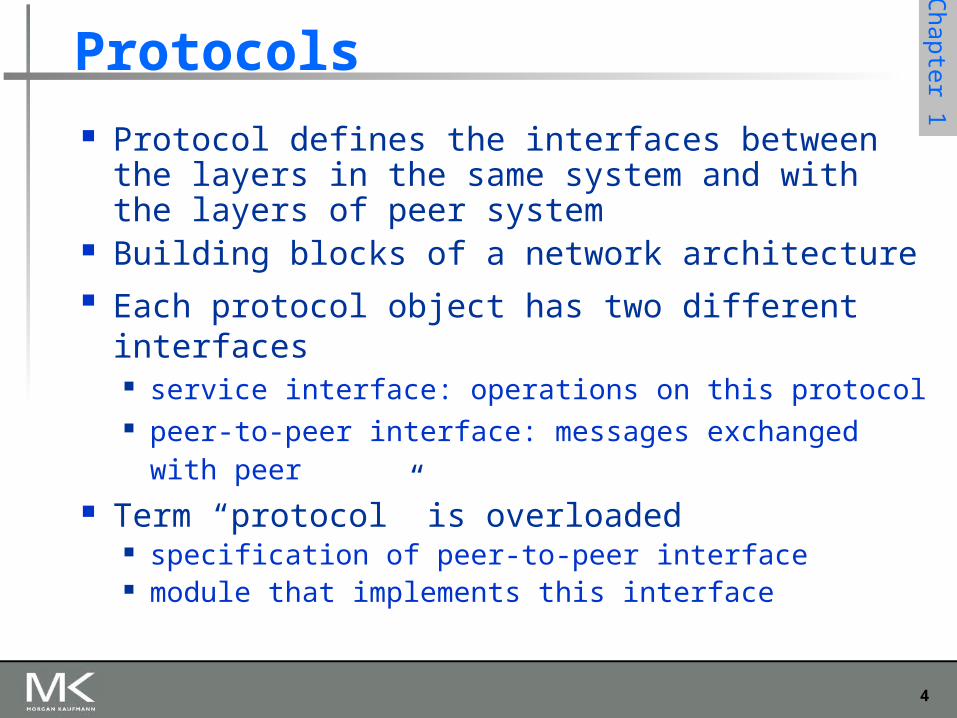
Protocol defines the interfaces between the layers in the same system and with the layers of peer system
Building blocks of a network architecture Each protocol object has two different interfaces
service interface: operations on this protocol peer-to-peer interface: messages exchanged with
peer Term “protocol” is overloaded
specification of peer-to-peer interface module that implements this interface
5
Chapter 1
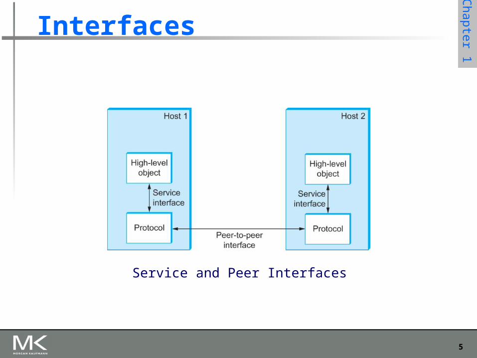
Interfaces
Service and Peer Interfaces
6
Chapter 1
Protocols
Protocol Specification: prose, pseudo-code, state transition diagram
Interoperable: when two or more protocols that implement the specification accurately
IETF: Internet Engineering Task Force
7
Chapter 1
Protocol Graph
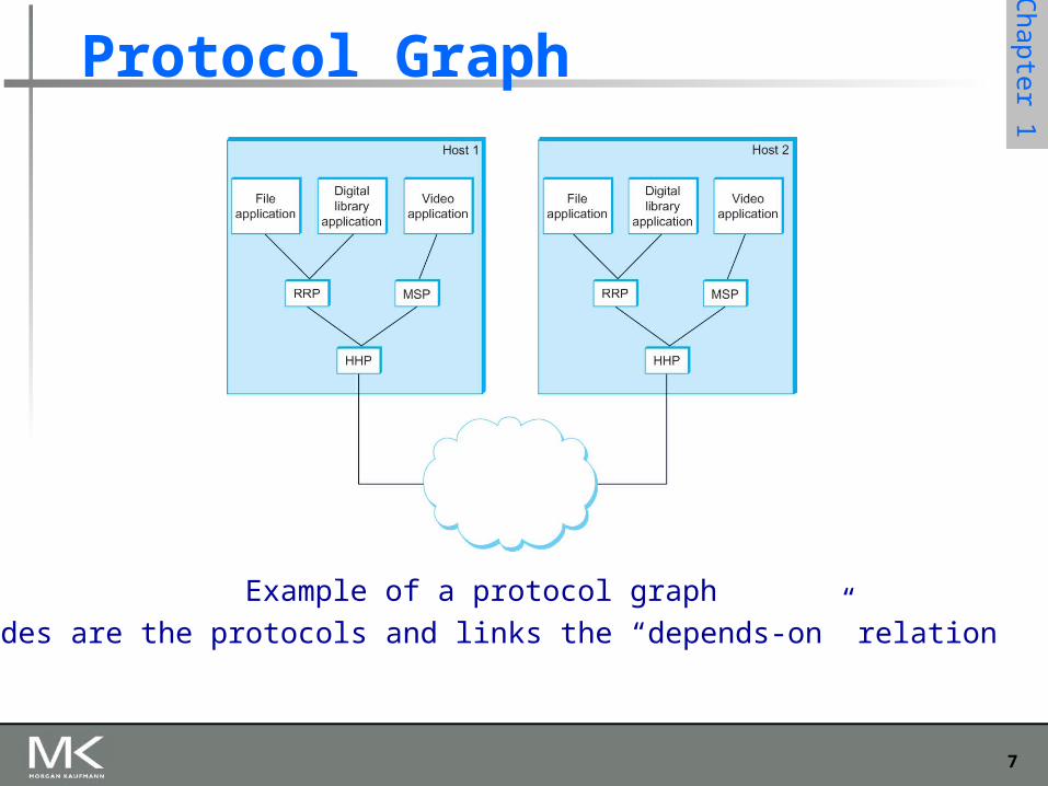
Example of a protocol graph
nodes are the protocols and links the “depends-on” relation
8
Chapter 1
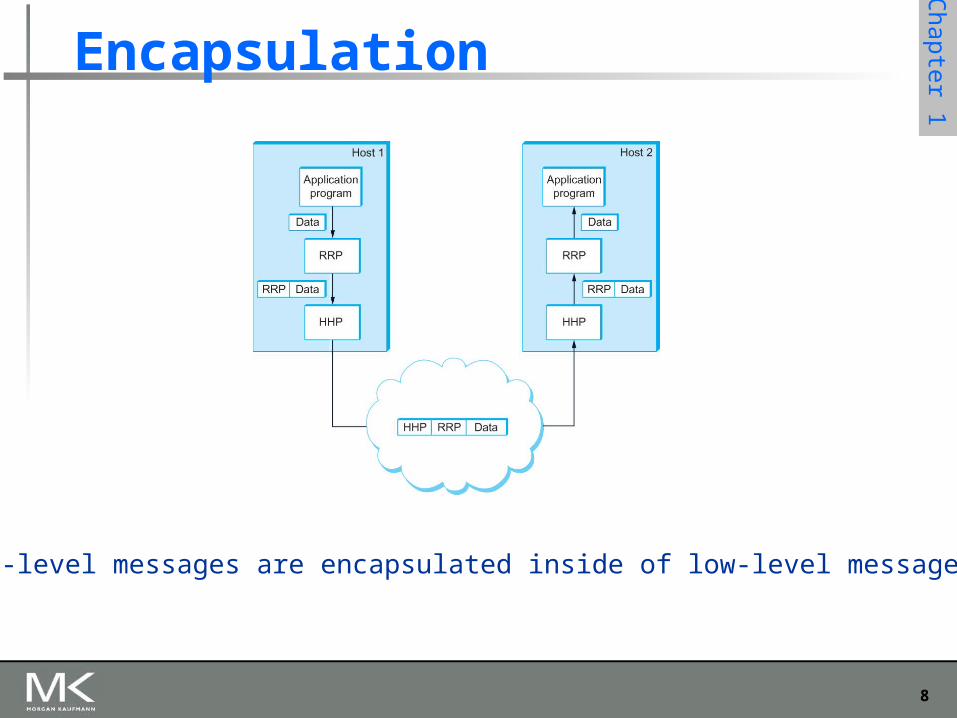
Encapsulation
High-level messages are encapsulated inside of low-level messages
9
Chapter 1
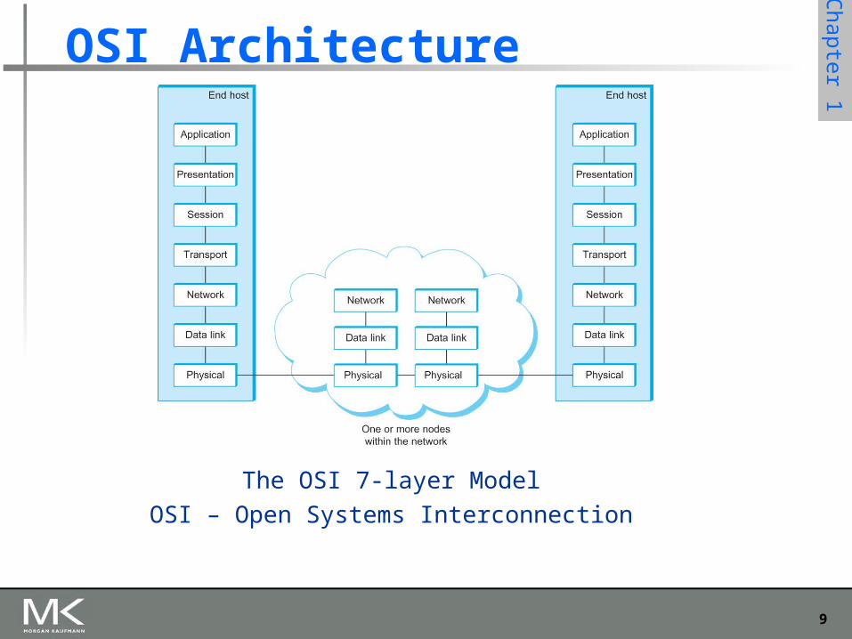
OSI Architecture
The OSI 7-layer Model
OSI – Open Systems Interconnection
10
Chapter 1
Description of Layers
Physical Layer Handles the transmission of raw bits over a communication link
Data Link Layer Collects a stream of bits into a larger aggregate called a frame Network adaptor along with device driver in OS implement the
protocol in this layer Frames are actually delivered to hosts
Network Layer Handles routing among nodes within a packet-switched network Unit of data exchanged between nodes in this layer is called a
packet
The lower three layers are implemented on all network nodes
11
Chapter 1
Description of Layers
Transport Layer Implements a process-to-process channel Unit of data exchanges in this layer is called a message
Session Layer Provides a name space that is used to tie together the potentially
different transport streams that are part of a single application Presentation Layer
Concerned about the format of data exchanged between peers Application Layer
Standardize common type of exchanges
The transport layer and the higher layers typically run only on end-hosts and not on the intermediate switches and routers
12
Chapter 1
Internet Architecture
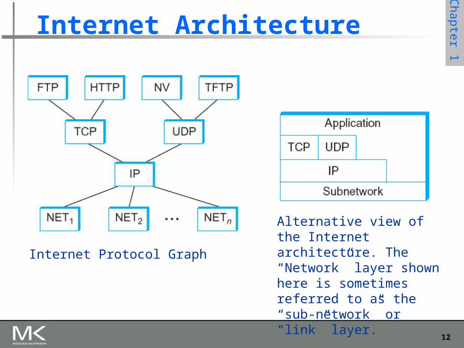
Internet Protocol Graph
Alternative view of the Internet architecture. The “Network” layer shown here is sometimes referred to as the “sub-network” or “link” layer.
13
Chapter 1
Internet Architecture
Defined by IETF Three main features
Does not imply strict layering. The application is free to bypass the defined transport layers and to directly use IP or other underlying networks
An hour-glass shape – wide at the top, narrow in the middle and wide at the bottom. IP serves as the focal point for the architecture
In order for a new protocol to be officially included in the architecture, there needs to be both a protocol specification and at least one (and preferably two) representative implementations of the specification
14
Chapter 1
Application Programming Interface
Interface exported by the network Since most network protocols are implemented (those in
the high protocol stack) in software and nearly all computer systems implement their network protocols as part of the operating system, when we refer to the interface “exported by the network”, we are generally referring to the interface that the OS provides to its networking subsystem
The interface is called the network Application Programming Interface (API)
15
Chapter 1
Application Programming Interface (Sockets)
Socket Interface was originally provided by the Berkeley distribution of Unix- Now supported in virtually all operating systems
Each protocol provides a certain set of services, and the API provides a syntax by which those services can be invoked in this particular OS
16
Chapter 1
Socket
What is a socket? The point where a local application process attaches
to the network An interface between an application and the network An application creates the socket
The interface defines operations for Creating a socket Attaching a socket to the network Sending and receiving messages through the socket Closing the socket
17
Chapter 1
Socket
Socket Family PF_INET denotes the Internet family PF_UNIX denotes the Unix pipe facility PF_PACKET denotes direct access to the network
interface (i.e., it bypasses the TCP/IP protocol stack)
Socket Type SOCK_STREAM is used to denote a byte stream SOCK_DGRAM is an alternative that denotes a
message oriented service, such as that provided by UDP
18
Chapter 1
Creating a Socket
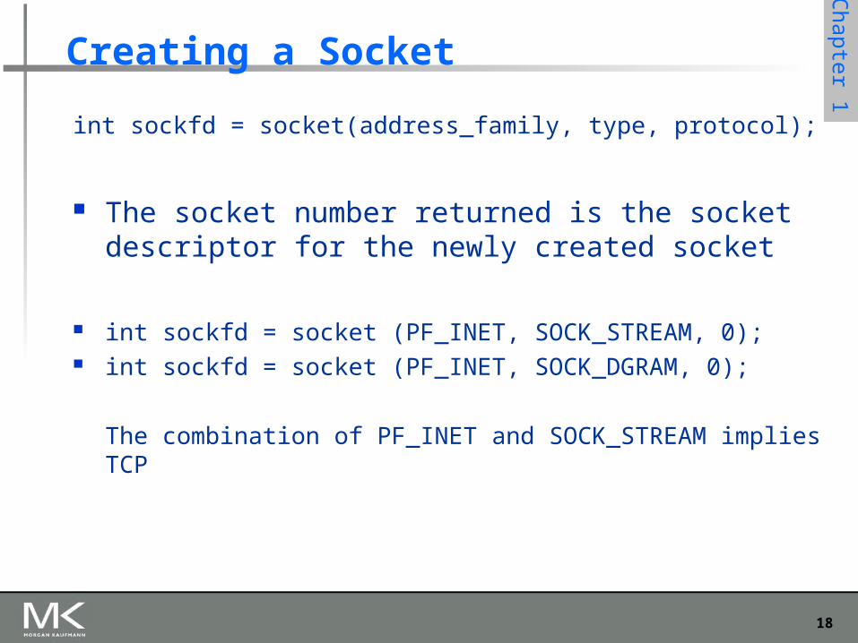
int sockfd = socket(address_family, type, protocol);
The socket number returned is the socket descriptor for the newly created socket
int sockfd = socket (PF_INET, SOCK_STREAM, 0); int sockfd = socket (PF_INET, SOCK_DGRAM, 0);
The combination of PF_INET and SOCK_STREAM implies TCP
19
Chapter 1
Client-Serve Model with TCP
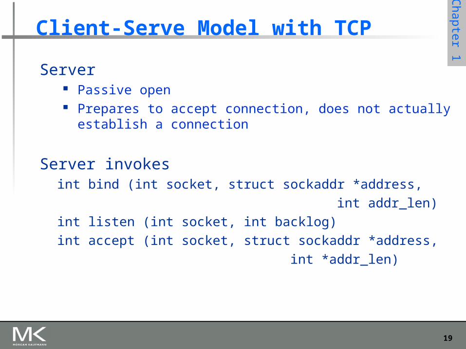
Server Passive open Prepares to accept connection, does not actually establish a
connection
Server invokesint bind (int socket, struct sockaddr *address,
int addr_len)
int listen (int socket, int backlog)
int accept (int socket, struct sockaddr *address,
int *addr_len)
20
Chapter 1
Client-Serve Model with TCP
Bind Binds the newly created socket to the specified address i.e. the
network address of the local participant (the server) Address is a data structure which combines IP and port
Listen Defines how many connections can be pending on the specified
socket
21
Chapter 1
Client-Serve Model with TCP
Accept Carries out the passive open Blocking operation
Does not return until a remote participant has established a connection
When it does, it returns a new socket that corresponds to the new established connection and the address argument contains the remote participant’s address
22
Chapter 1
Client-Serve Model with TCP
Client Application performs active open It says who it wants to communicate with
Client invokes
int connect (int socket, struct sockaddr *address,
int addr_len)
Connect Does not return until TCP has successfully established a
connection at which application is free to begin sending data Address contains remote machine’s address
23
Chapter 1
Client-Serve Model with TCP
In practice The client usually specifies only remote participant’s
address and let’s the system fill in the local information
Whereas a server usually listens for messages on a well-known port
A client does not care which port it uses for itself, the OS simply selects an unused one
24
Chapter 1
Client-Serve Model with TCP
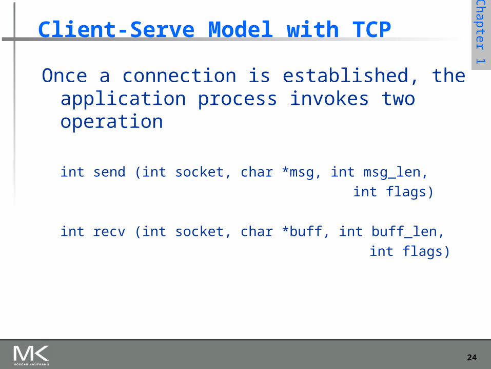
Once a connection is established, the application process invokes two operation
int send (int socket, char *msg, int msg_len,
int flags)
int recv (int socket, char *buff, int buff_len,
int flags)
25
Chapter 1
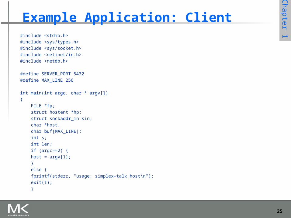
Example Application: Client#include <stdio.h>
#include <sys/types.h>
#include <sys/socket.h>
#include <netinet/in.h>
#include <netdb.h>
#define SERVER_PORT 5432
#define MAX_LINE 256
int main(int argc, char * argv[])
{
FILE *fp;
struct hostent *hp;
struct sockaddr_in sin;
char *host;
char buf[MAX_LINE];
int s;
int len;
if (argc==2) {
host = argv[1];
}
else {
fprintf(stderr, "usage: simplex-talk host\n");
exit(1);
}
26
Chapter 1
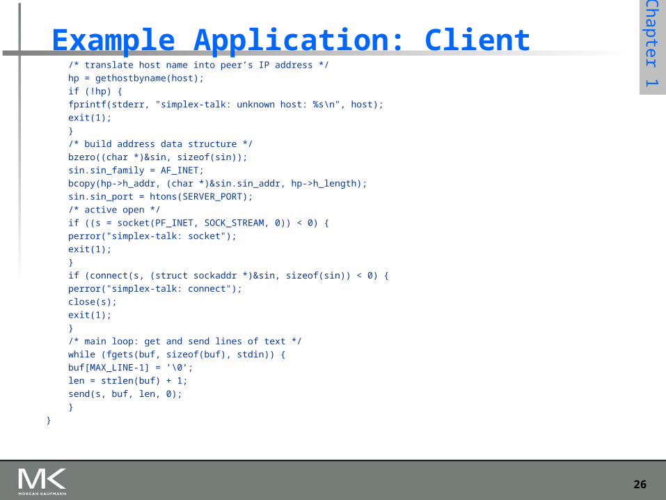
Example Application: Client/* translate host name into peer’s IP address */
hp = gethostbyname(host);
if (!hp) {
fprintf(stderr, "simplex-talk: unknown host: %s\n", host);
exit(1);
}
/* build address data structure */
bzero((char *)&sin, sizeof(sin));
sin.sin_family = AF_INET;
bcopy(hp->h_addr, (char *)&sin.sin_addr, hp->h_length);
sin.sin_port = htons(SERVER_PORT);
/* active open */
if ((s = socket(PF_INET, SOCK_STREAM, 0)) < 0) {
perror("simplex-talk: socket");
exit(1);
}
if (connect(s, (struct sockaddr *)&sin, sizeof(sin)) < 0) {
perror("simplex-talk: connect");
close(s);
exit(1);
}
/* main loop: get and send lines of text */
while (fgets(buf, sizeof(buf), stdin)) {
buf[MAX_LINE-1] = ’\0’;
len = strlen(buf) + 1;
send(s, buf, len, 0);
}
}
27
Chapter 1
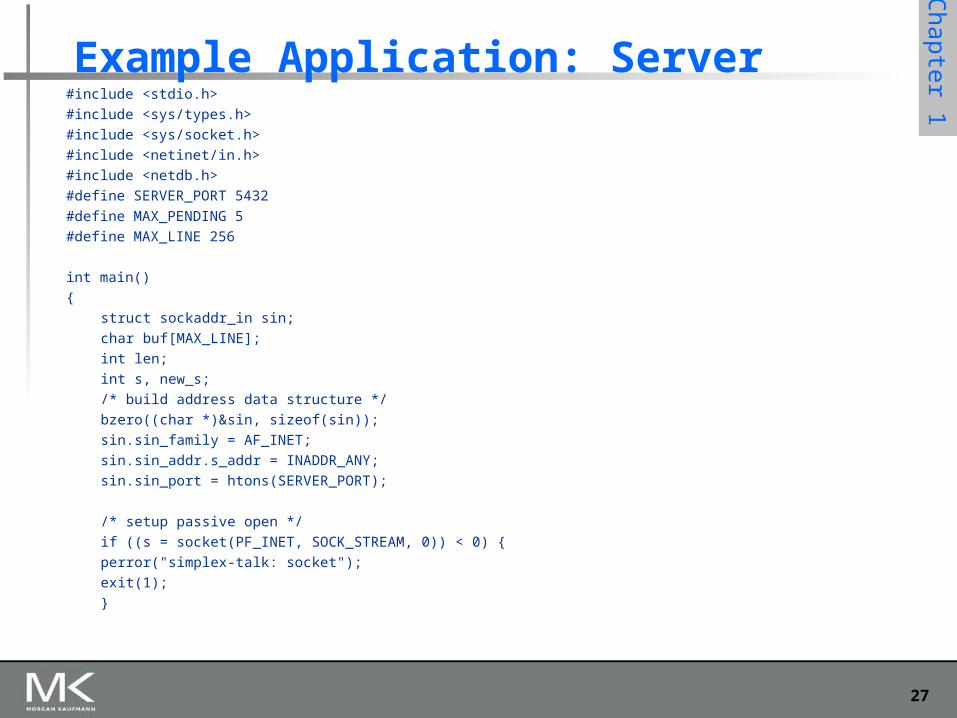
Example Application: Server#include <stdio.h>
#include <sys/types.h>
#include <sys/socket.h>
#include <netinet/in.h>
#include <netdb.h>
#define SERVER_PORT 5432
#define MAX_PENDING 5
#define MAX_LINE 256
int main()
{
struct sockaddr_in sin;
char buf[MAX_LINE];
int len;
int s, new_s;
/* build address data structure */
bzero((char *)&sin, sizeof(sin));
sin.sin_family = AF_INET;
sin.sin_addr.s_addr = INADDR_ANY;
sin.sin_port = htons(SERVER_PORT);
/* setup passive open */
if ((s = socket(PF_INET, SOCK_STREAM, 0)) < 0) {
perror("simplex-talk: socket");
exit(1);
}
28
Chapter 1
Example Application: Serverif ((bind(s, (struct sockaddr *)&sin, sizeof(sin))) < 0) {
perror("simplex-talk: bind");
exit(1);
}
listen(s, MAX_PENDING);
/* wait for connection, then receive and print text */
while(1) {
if ((new_s = accept(s, (struct sockaddr *)&sin, &len)) < 0) {
perror("simplex-talk: accept");
exit(1);
}
while (len = recv(new_s, buf, sizeof(buf), 0))
fputs(buf, stdout);
close(new_s);
}
}
29
Chapter 1
Performance
Bandwidth Width of the frequency band Number of bits per second that can be transmitted over a
communication link 1 Mbps: 1 x 106 bits/second = 1x220 bits/sec 1 x 10⁻⁶ seconds to transmit each bit or imagine that a
timeline, now each bit occupies 1 micro second space. On a 2 Mbps link the width is 0.5 micro second. Smaller the width more will be transmission per unit time.
30
Chapter 1
Bandwidth
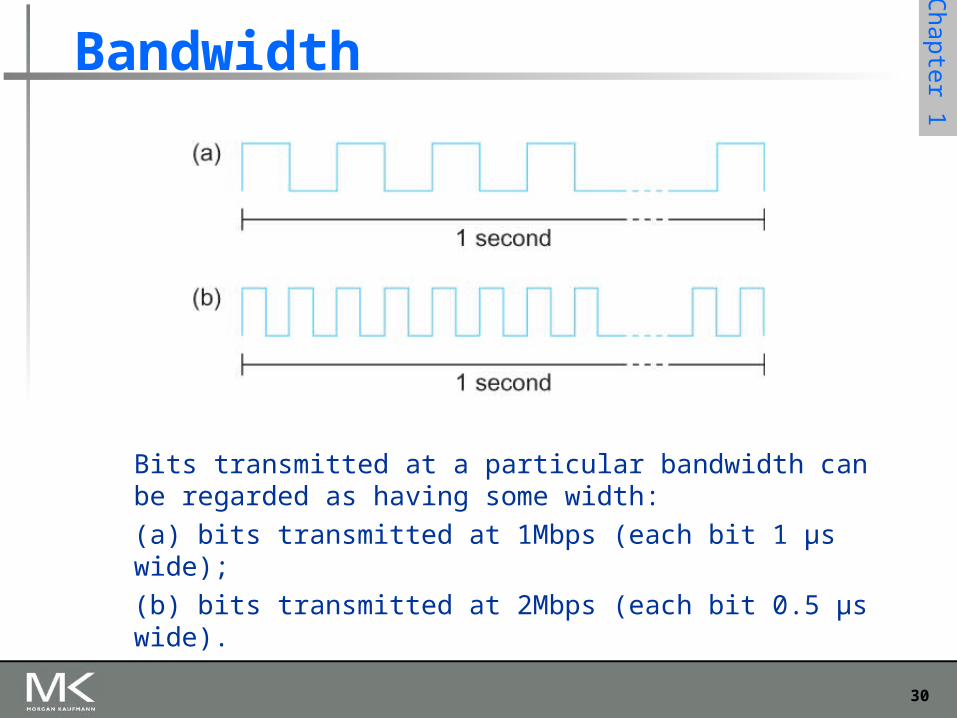
Bits transmitted at a particular bandwidth can be regarded as having some width:
(a) bits transmitted at 1Mbps (each bit 1 μs wide);
(b) bits transmitted at 2Mbps (each bit 0.5 μs wide).
31
Chapter 1
Performance
Latency = Propagation + transmit + queue Propagation = distance/speed of light Transmit = size/bandwidth
One bit transmission => propagation is important Large bytes transmission => bandwidth is important
32
Chapter 1
Delay X Bandwidth
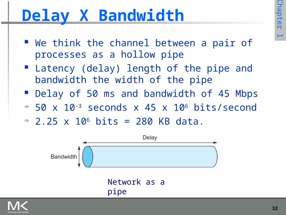
We think the channel between a pair of processes as a hollow pipe
Latency (delay) length of the pipe and bandwidth the width of the pipe
Delay of 50 ms and bandwidth of 45 Mbps 50 x 10-3 seconds x 45 x 106 bits/second 2.25 x 106 bits = 280 KB data.
Network as a pipe
33
Chapter 1
Delay X Bandwidth
Relative importance of bandwidth and latency depends on application For large file transfer, bandwidth is critical For small messages (HTTP, NFS, etc.), latency is
critical Variance in latency (jitter) can also affect some
applications (e.g., audio/video conferencing)
34
Chapter 1
Delay X Bandwidth
How many bits the sender must transmit before the first bit arrives at the receiver if the sender keeps the pipe full
Takes another one-way latency to receive a response from the receiver
If the sender does not fill the pipe—send a whole delay × bandwidth product’s worth of data before it stops to wait for a signal—the sender will not fully utilize the network
35
Chapter 1
Delay X Bandwidth
Infinite bandwidth RTT dominates Throughput = TransferSize / TransferTime TransferTime = RTT + 1/Bandwidth x
TransferSize Its all relative
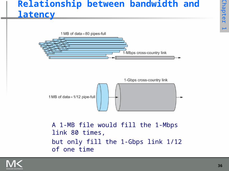
1-MB file to 1-Gbps link looks like a 1-KB packet to 1-Mbps link
36
Chapter 1
Relationship between bandwidth and latency
A 1-MB file would fill the 1-Mbps link 80 times,
but only fill the 1-Gbps link 1/12 of one time
37
Computer Networks: A Systems Approach, 5eLarry L. Peterson and Bruce S. Davie
Chapter 2
Getting Connected
Copyright © 2010, Elsevier Inc. All rights Reserved
38
Chapter 1
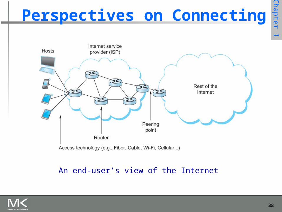
Perspectives on Connecting
An end-user’s view of the Internet
39
Chapter 1
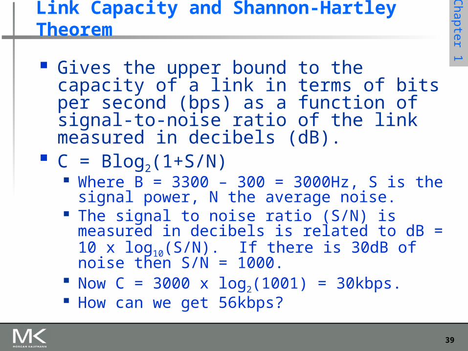
Link Capacity and Shannon-Hartley Theorem
Gives the upper bound to the capacity of a link in terms of bits per second (bps) as a function of signal-to-noise ratio of the link measured in decibels (dB).
C = Blog2(1+S/N) Where B = 3300 – 300 = 3000Hz, S is the signal
power, N the average noise. The signal to noise ratio (S/N) is measured in decibels
is related to dB = 10 x log10(S/N). If there is 30dB of noise then S/N = 1000.
Now C = 3000 x log2(1001) = 30kbps. How can we get 56kbps?
40
Chapter 1
Links
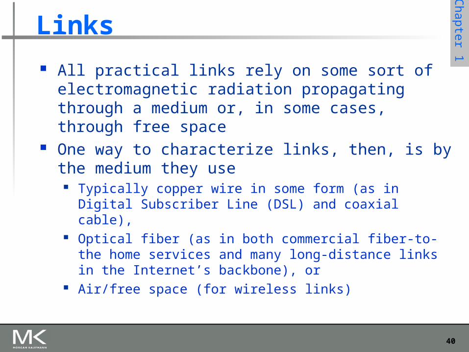
All practical links rely on some sort of electromagnetic radiation propagating through a medium or, in some cases, through free space
One way to characterize links, then, is by the medium they use
Typically copper wire in some form (as in Digital Subscriber Line (DSL) and coaxial cable),
Optical fiber (as in both commercial fiber-to-the home services and many long-distance links in the Internet’s backbone), or
Air/free space (for wireless links)
41
Chapter 1
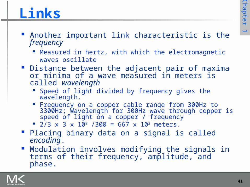
Links Another important link characteristic is the frequency
Measured in hertz, with which the electromagnetic waves oscillate
Distance between the adjacent pair of maxima or minima of a wave measured in meters is called wavelength
Speed of light divided by frequency gives the wavelength. Frequency on a copper cable range from 300Hz to 3300Hz;
Wavelength for 300Hz wave through copper is speed of light on a copper / frequency
2/3 x 3 x 108 /300 = 667 x 103 meters. Placing binary data on a signal is called encoding. Modulation involves modifying the signals in terms of
their frequency, amplitude, and phase.
42
Chapter 1
Links
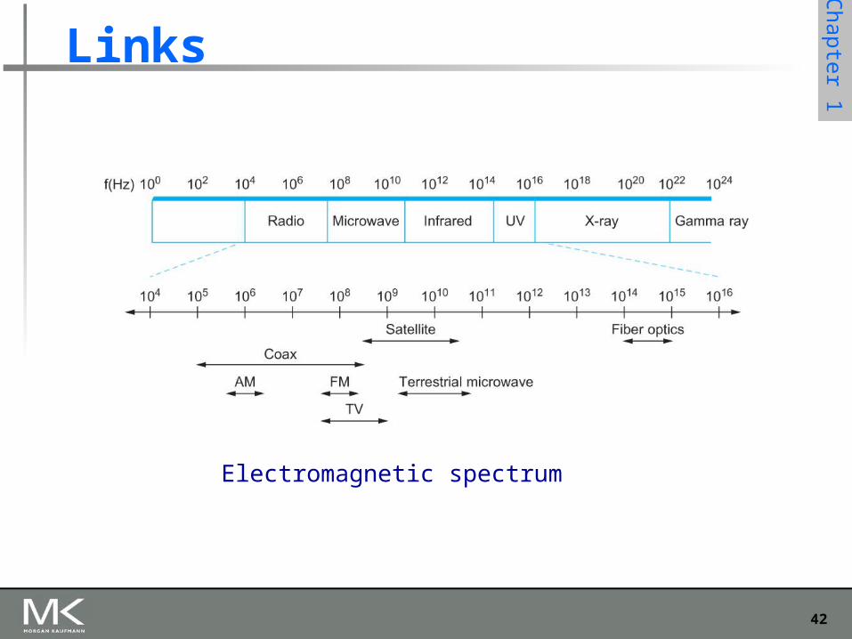
Electromagnetic spectrum
43
Chapter 1
Links
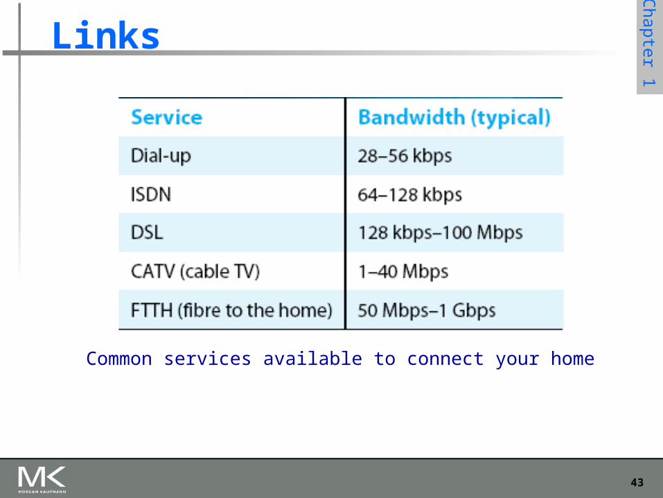
Common services available to connect your home
44
Chapter 1
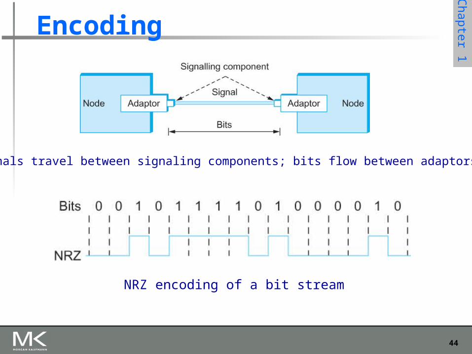
Encoding
Signals travel between signaling components; bits flow between adaptors
NRZ encoding of a bit stream
45
Chapter 1
Encoding
Problem with NRZ Baseline wander
The receiver keeps an average of the signals it has seen so far
Uses the average to distinguish between low and high signal
When a signal is significantly low than the average, it is 0, else it is 1
Too many consecutive 0’s and 1’s cause this average to change, making it difficult to detect
46
Chapter 1
Encoding
Problem with NRZ Clock recovery
Frequent transition from high to low or vice versa are necessary to enable clock recovery
Both the sending and decoding process is driven by a clock
Every clock cycle, the sender transmits a bit and the receiver recovers a bit
The sender and receiver have to be precisely synchronized
47
Chapter 1
Encoding
NRZI Non Return to Zero Inverted Sender makes a transition from the current
signal to encode 1 and stay at the current signal to encode 0
Solves for consecutive 1’s
48
Chapter 1
Encoding
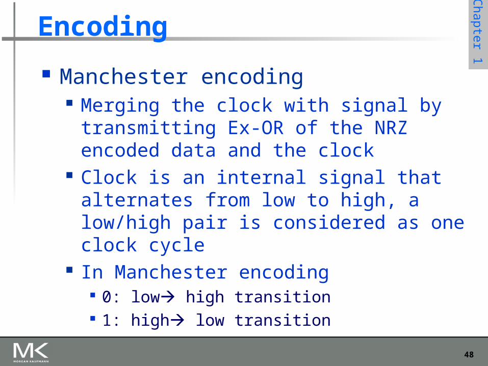
Manchester encoding Merging the clock with signal by transmitting
Ex-OR of the NRZ encoded data and the clock Clock is an internal signal that alternates from
low to high, a low/high pair is considered as one clock cycle
In Manchester encoding 0: low high transition 1: high low transition
49
Chapter 1
Encoding
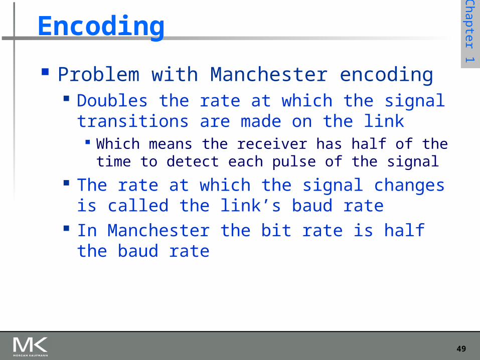
Problem with Manchester encoding Doubles the rate at which the signal
transitions are made on the link Which means the receiver has half of the time to
detect each pulse of the signal The rate at which the signal changes is called
the link’s baud rate In Manchester the bit rate is half the baud rate
50
Chapter 1
Encoding
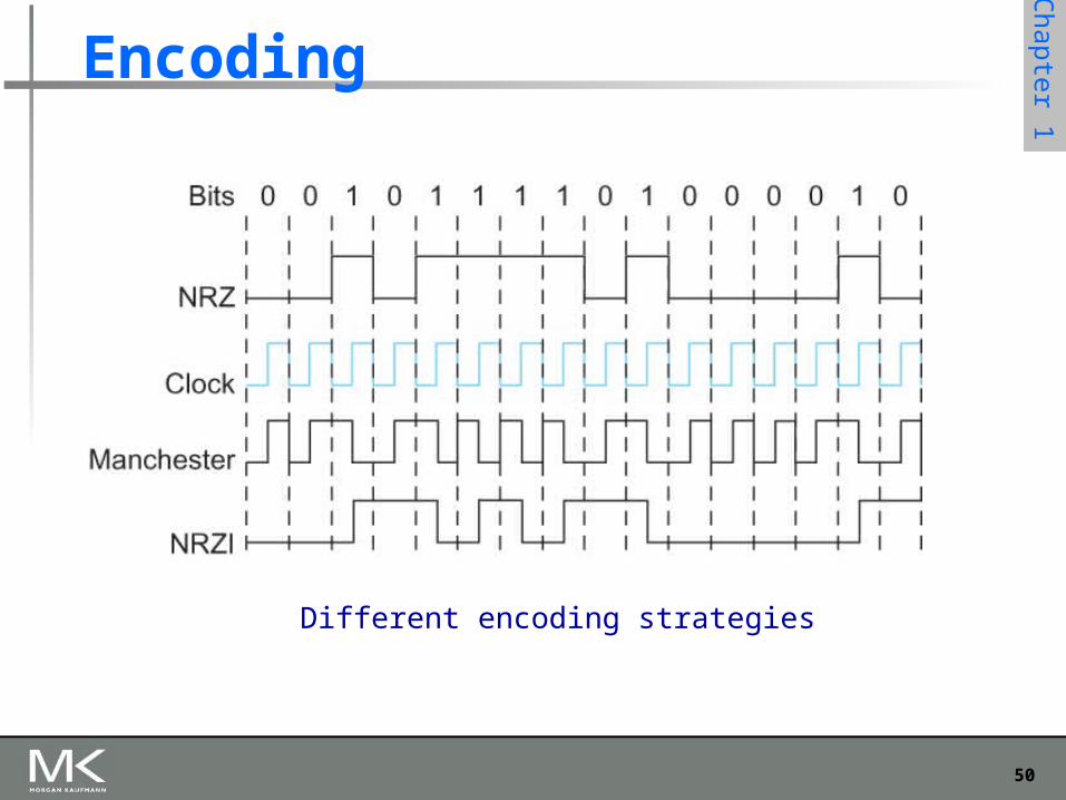
Different encoding strategies
51
Chapter 1
Encoding
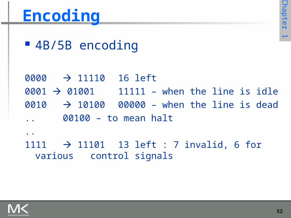
4B/5B encoding Insert extra bits into bit stream so as to break up the
long sequence of 0’s and 1’s Every 4-bits of actual data are encoded in a 5- bit
code that is transmitted to the receiver 5-bit codes are selected in such a way that each one
has no more than one leading 0(zero) and no more than two trailing 0’s.
No pair of 5-bit codes results in more than three consecutive 0’s
52
Chapter 1
Encoding
4B/5B encoding
0000 11110 16 left
0001 01001 11111 – when the line is idle
0010 10100 00000 – when the line is dead
.. 00100 – to mean halt
..
1111 11101 13 left : 7 invalid, 6 for various control signals
53
Chapter 1
Framing
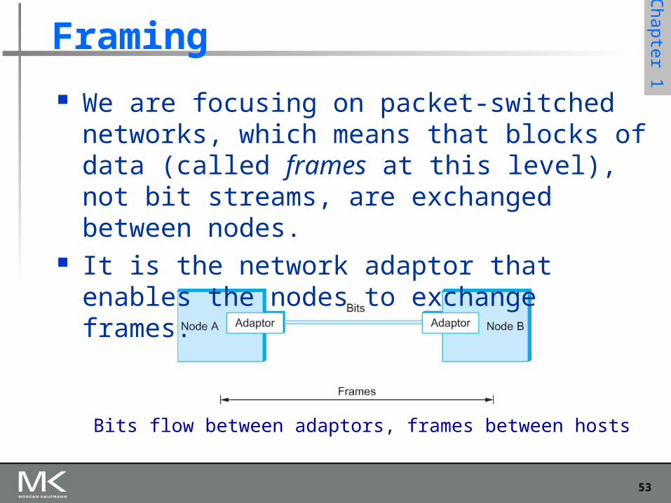
We are focusing on packet-switched networks, which means that blocks of data (called frames at this level), not bit streams, are exchanged between nodes.
It is the network adaptor that enables the nodes to exchange frames.
Bits flow between adaptors, frames between hosts
54
Chapter 1
Framing
When node A wishes to transmit a frame to node B, it tells its adaptor to transmit a frame from the node’s memory. This results in a sequence of bits being sent over the link.
The adaptor on node B then collects together the sequence of bits arriving on the link and deposits the corresponding frame in B’s memory.
Recognizing exactly what set of bits constitute a frame—that is, determining where the frame begins and ends—is the central challenge faced by the adaptor

55
Chapter 1
Framing Byte-oriented Protocols
To view each frame as a collection of bytes (characters) rather than bits
BISYNC (Binary Synchronous Communication) Protocol
Developed by IBM (late 1960) DDCMP (Digital Data Communication Protocol)
Used in DECNet

56
Chapter 1
Framing
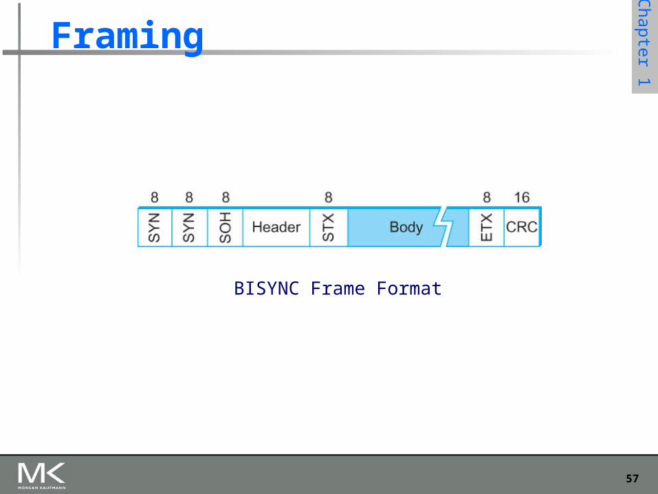
BISYNC – sentinel approach Frames transmitted beginning with leftmost field Beginning of a frame is denoted by sending a special
SYN (synchronize) character Data portion of the frame is contained between
special sentinel character STX (start of text) and ETX (end of text)
SOH : Start of Header DLE : Data Link Escape CRC: Cyclic Redundancy Check
57
Chapter 1
Framing
BISYNC Frame Format
58
Chapter 1
Framing
Recent PPP which is commonly run over Internet links uses sentinel approach Special start of text character denoted as Flag
0 1 1 1 1 1 1 0 Address, control : default numbers Protocol for demux : IP / IPX Payload : negotiated (1500 bytes) Checksum : for error detection
59
Chapter 1
Framing
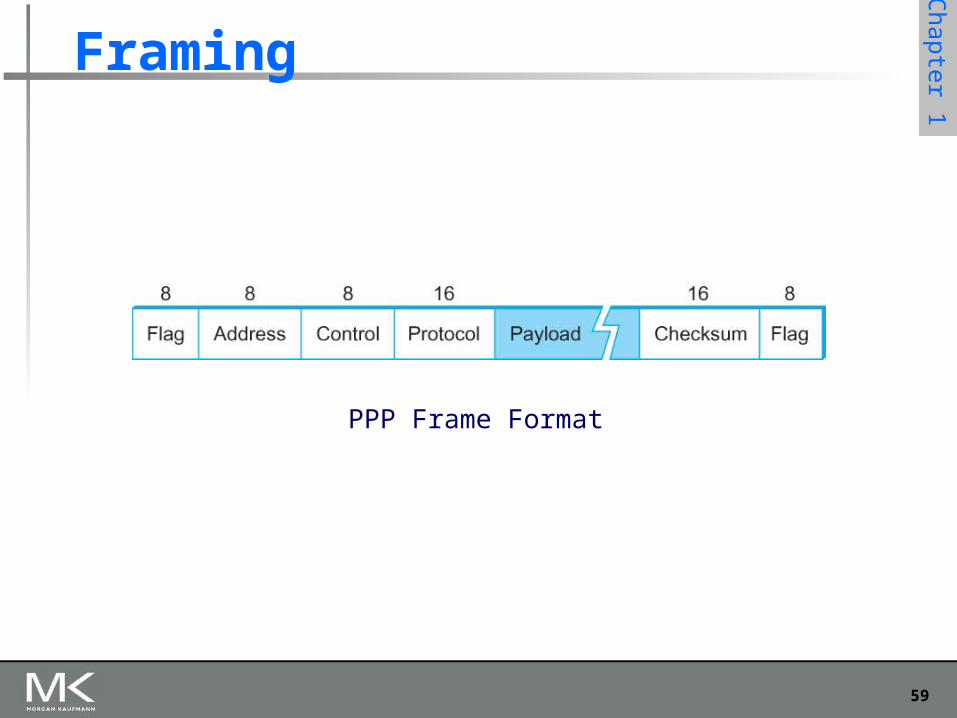
PPP Frame Format
60
Chapter 1
Framing
Byte-counting approach DDCMP count : how many bytes are contained in the
frame body If count is corrupted
Framing error
61
Chapter 1
Framing
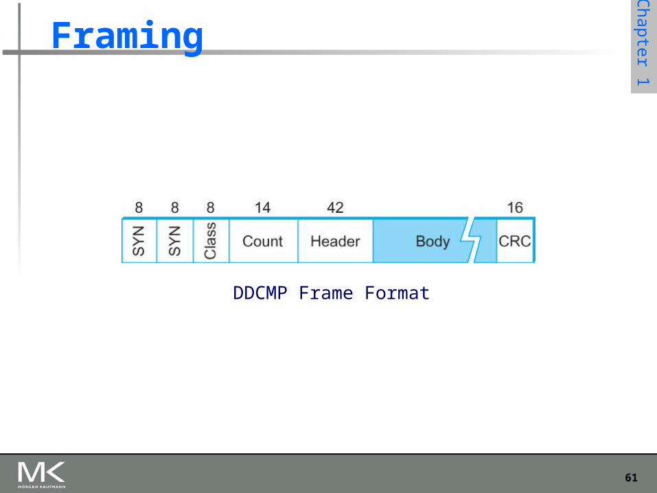
DDCMP Frame Format
62
Chapter 1
Framing
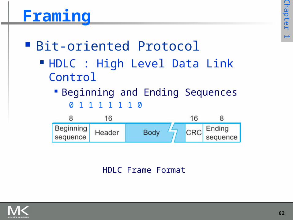
Bit-oriented Protocol HDLC : High Level Data Link Control
Beginning and Ending Sequences0 1 1 1 1 1 1 0
HDLC Frame Format
63
Chapter 1
Framing
HDLC Protocol On the sending side, any time five
consecutive 1’s have been transmitted from the body of the message (i.e. excluding when the sender is trying to send the distinguished 01111110 sequence)
The sender inserts 0 before transmitting the next bit
64
Chapter 1
Framing
HDLC Protocol On the receiving side
5 consecutive 1’s Next bit 0 : Stuffed, so discard it
1 : Either End of the frame marker Or Error has been introduced
in the bitstreamLook at the next bitIf 0 ( 01111110 ) End of the frame markerIf 1 ( 01111111 ) Error, discard the whole frame
The receiver needs to wait for next
01111110 before it can start
receiving again
65
Chapter 1
Error Detection
Bit errors are introduced into frames Because of electrical interference and thermal noises
Detecting Error Correction Error Two approaches when the recipient detects an
error Notify the sender that the message was corrupted, so
the sender can send again. If the error is rare, then the retransmitted message will be
error-free Using some error correct detection and correction
algorithm, the receiver reconstructs the message
66
Chapter 1
Error Detection
Common technique for detecting transmission error CRC (Cyclic Redundancy Check)
Used in HDLC, DDCMP, CSMA/CD, Token Ring Other approaches
Two Dimensional Parity (BISYNC) Checksum (IP)
67
Chapter 1
Error Detection
Basic Idea of Error Detection To add redundant information to a frame that can be
used to determine if errors have been introduced Imagine (Extreme Case)
Transmitting two complete copies of data Identical No error Differ Error Poor Scheme ???
n bit message, n bit redundant information Error can go undetected
In general, we can provide strong error detection technique k redundant bits, n bits message, k << n In Ethernet, a frame carrying up to 12,000 bits of data requires only 32-
bit CRC
68
Chapter 1
Error Detection
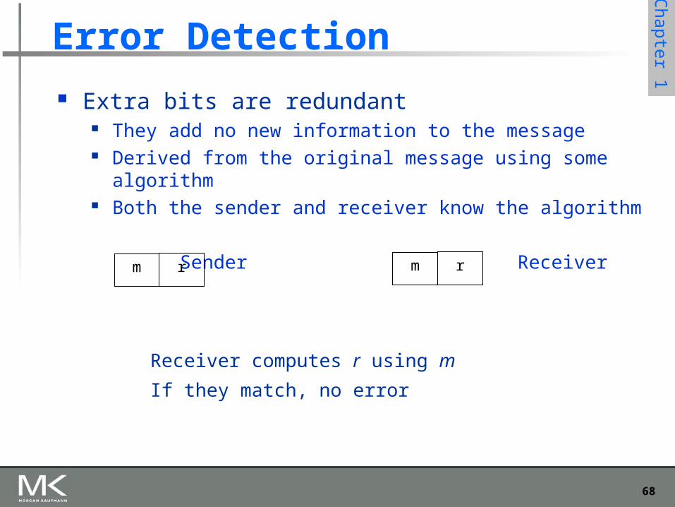
Extra bits are redundant They add no new information to the message Derived from the original message using some algorithm Both the sender and receiver know the algorithm
Sender Receiver
Receiver computes r using m
If they match, no error
m rm r
69
Chapter 1
Internet Checksum Algorithm
Not used at the link level Add up all the words that are transmitted and
then transmit the result of that sum The result is called the checksum
The receiver performs the same calculation on the received data and compares the result with the received checksum
If any transmitted data, including the checksum itself, is corrupted, then the results will not match, so the receiver knows that an error occurred
70
Chapter 1
Reliable Transmission
CRC is used to detect errors. Some error codes are strong enough to correct
errors. The overhead is typically too high. Corrupt frames must be discarded. A link-level protocol that wants to deliver frames
reliably must recover from these discarded frames.
This is accomplished using a combination of two fundamental mechanisms Acknowledgements and Timeouts
71
Chapter 1
Reliable Transmission
An acknowledgement (ACK for short) is a small control frame that a protocol sends back to its peer saying that it has received the earlier frame. A control frame is a frame with header only (no data).
The receipt of an acknowledgement indicates to the sender of the original frame that its frame was successfully delivered.
72
Chapter 1
Reliable Transmission
If the sender does not receive an acknowledgment after a reasonable amount of time, then it retransmits the original frame.
The action of waiting a reasonable amount of time is called a timeout.
The general strategy of using acknowledgements and timeouts to implement reliable delivery is sometimes called Automatic Repeat reQuest (ARQ).
73
Chapter 1
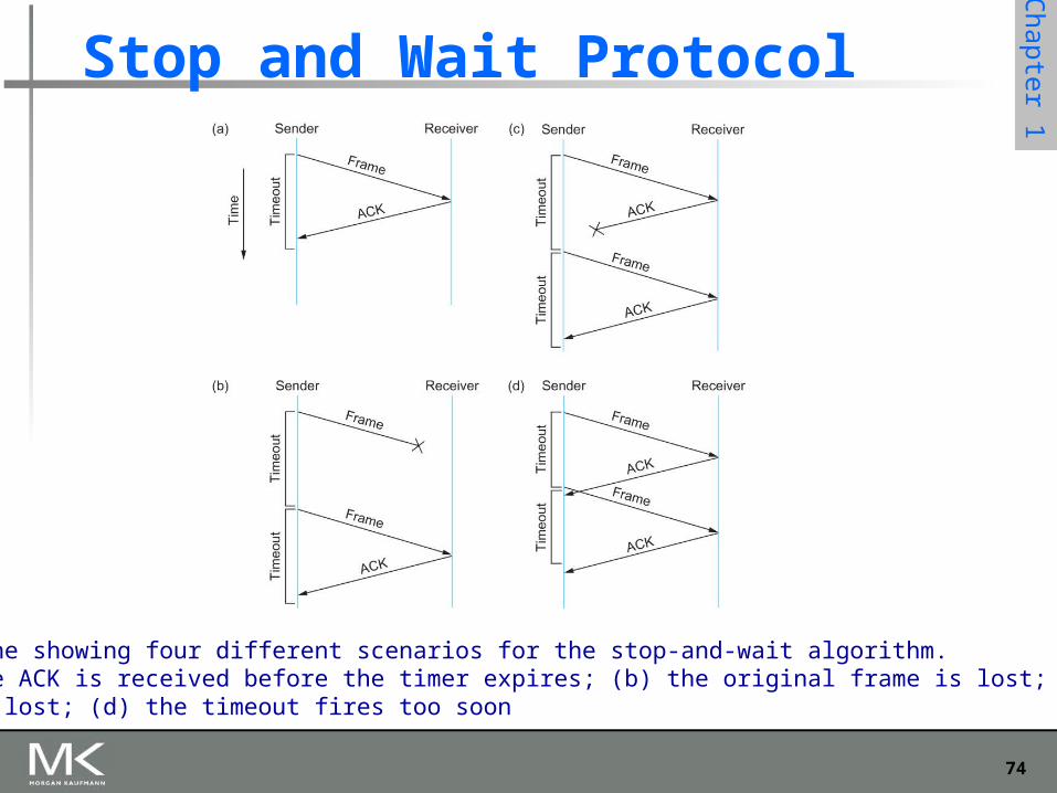
Stop and Wait Protocol
Idea of stop-and-wait protocol is straightforward
After transmitting one frame, the sender waits for an acknowledgement before transmitting the next frame.
If the acknowledgement does not arrive after a certain period of time, the sender times out and retransmits the original frame
74
Chapter 1
Stop and Wait Protocol
Timeline showing four different scenarios for the stop-and-wait algorithm.(a) The ACK is received before the timer expires; (b) the original frame is lost; (c) theACK is lost; (d) the timeout fires too soon
75
Chapter 1
Stop and Wait Protocol
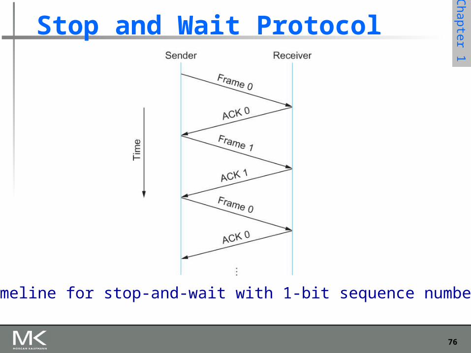
If the acknowledgment is lost or delayed in arriving The sender times out and retransmits the original frame, but the
receiver will think that it is the next frame since it has correctly received and acknowledged the first frame
As a result, duplicate copies of frames will be delivered
How to solve this Use 1 bit sequence number (0 or 1) When the sender retransmits frame 0, the receiver can
determine that it is seeing a second copy of frame 0 rather than the first copy of frame 1 and therefore can ignore it (the receiver still acknowledges it, in case the first acknowledgement was lost)
76
Chapter 1
Stop and Wait Protocol
Timeline for stop-and-wait with 1-bit sequence number
77
Chapter 1
Stop and Wait Protocol
The sender has only one outstanding frame on the link at a time
This may be far below the link’s capacity Consider a 1.5 Mbps link with a 45 ms RTT
The link has a delay bandwidth product of 67.5 Kb or approximately 8 KB
Since the sender can send only one frame per RTT and assuming a frame size of 1 KB
Maximum Sending rate Bits per frame Time per frame = 1024 8 0.045 = 182 Kbps
Or about one-eighth of the link’s capacity
To use the link fully, then sender should transmit up to eight frames before having to wait for an acknowledgement
78
Chapter 1
Sliding Window Protocol
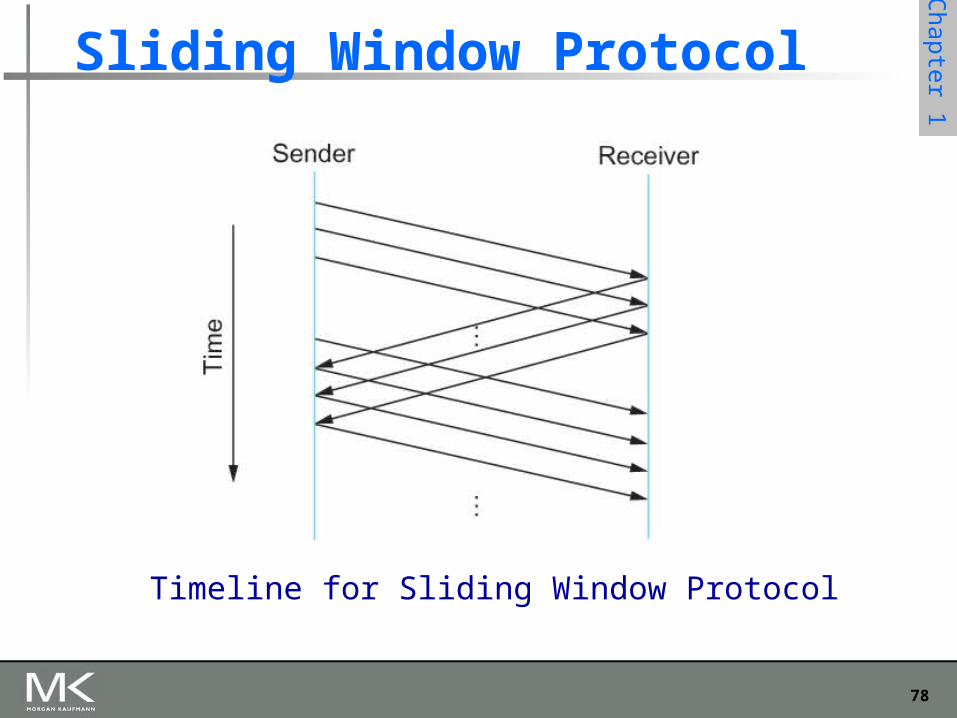
Timeline for Sliding Window Protocol
79
Chapter 1
Sliding Window Protocol
Sender assigns a sequence number denoted as SeqNum to each frame.
Assume it can grow infinitely large
Sender maintains three variables Sending Window Size (SWS)
Upper bound on the number of outstanding (unacknowledged) frames that the sender can transmit
Last Acknowledgement Received (LAR) Sequence number of the last acknowledgement received
Last Frame Sent (LFS) Sequence number of the last frame sent
80
Chapter 1
Sliding Window Protocol
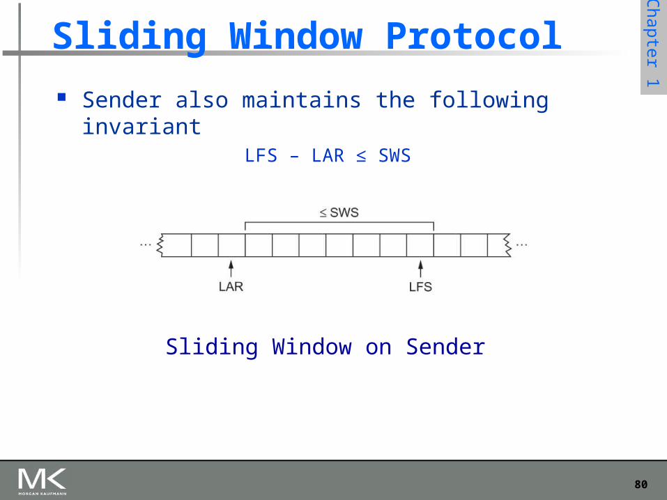
Sender also maintains the following invariantLFS – LAR ≤ SWS
Sliding Window on Sender
81
Chapter 1
Sliding Window Protocol
When an acknowledgement arrives the sender moves LAR to right, thereby allowing the sender to
transmit another frame Also the sender associates a timer with each frame it
transmits It retransmits the frame if the timer expires before the ACK is
received Note that the sender has to be willing to buffer up to
SWS frames WHY?
82
Chapter 1
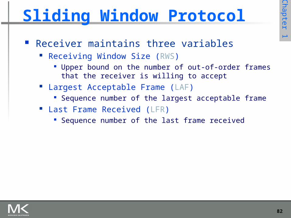
Sliding Window Protocol
Receiver maintains three variables Receiving Window Size (RWS)
Upper bound on the number of out-of-order frames that the receiver is willing to accept
Largest Acceptable Frame (LAF) Sequence number of the largest acceptable frame
Last Frame Received (LFR) Sequence number of the last frame received
83
Chapter 1
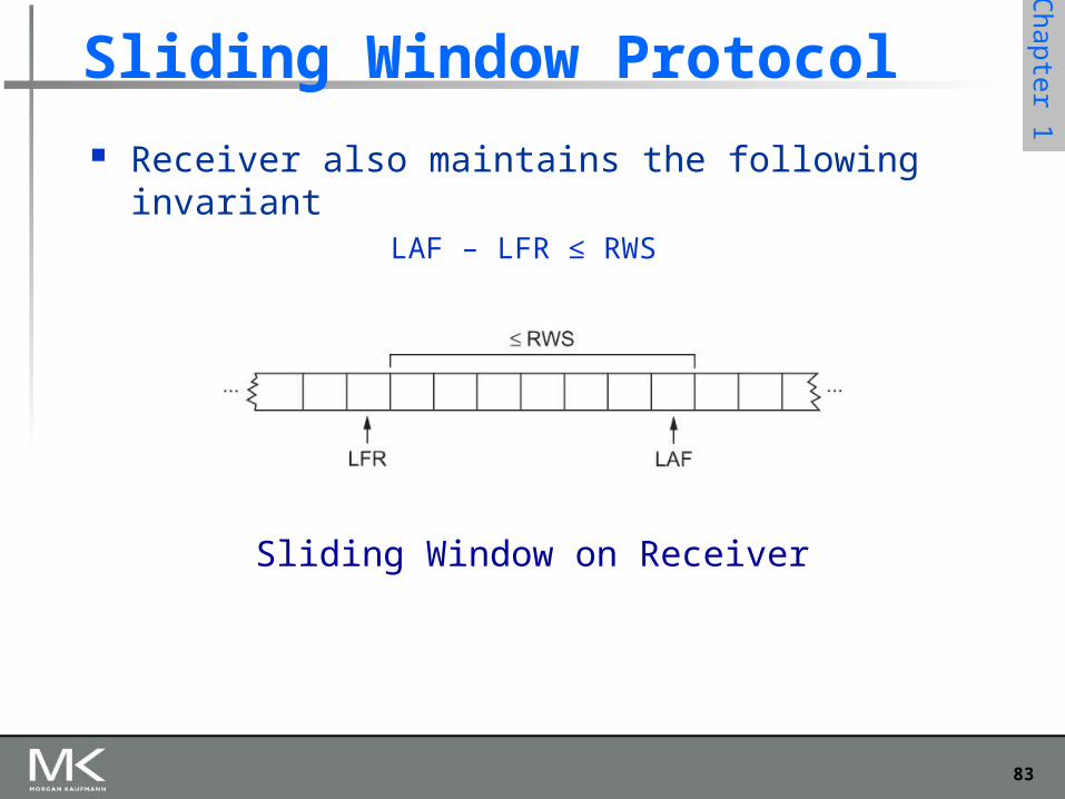
Sliding Window Protocol
Receiver also maintains the following invariantLAF – LFR ≤ RWS
Sliding Window on Receiver
84
Chapter 1
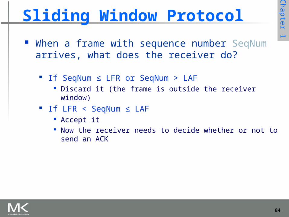
Sliding Window Protocol
When a frame with sequence number SeqNum arrives, what does the receiver do?
If SeqNum ≤ LFR or SeqNum > LAF Discard it (the frame is outside the receiver window)
If LFR < SeqNum ≤ LAF Accept it Now the receiver needs to decide whether or not to send an ACK
85
Chapter 1
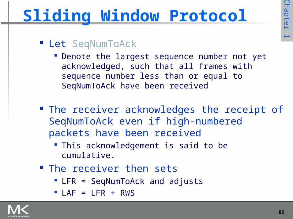
Sliding Window Protocol
Let SeqNumToAck Denote the largest sequence number not yet acknowledged,
such that all frames with sequence number less than or equal to SeqNumToAck have been received
The receiver acknowledges the receipt of SeqNumToAck even if high-numbered packets have been received
This acknowledgement is said to be cumulative. The receiver then sets
LFR = SeqNumToAck and adjusts LAF = LFR + RWS
86
Chapter 1
Sliding Window Protocol
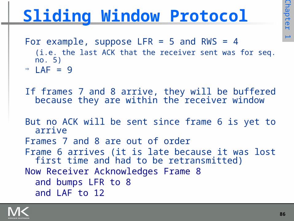
For example, suppose LFR = 5 and RWS = 4 (i.e. the last ACK that the receiver sent was for seq. no. 5)
LAF = 9
If frames 7 and 8 arrive, they will be buffered because they are within the receiver window
But no ACK will be sent since frame 6 is yet to arriveFrames 7 and 8 are out of orderFrame 6 arrives (it is late because it was lost first time and
had to be retransmitted)Now Receiver Acknowledges Frame 8
and bumps LFR to 8and LAF to 12
87
Chapter 1
Issues with Sliding Window Protocol
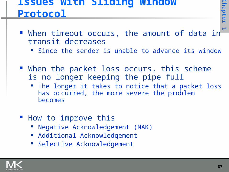
When timeout occurs, the amount of data in transit decreases
Since the sender is unable to advance its window
When the packet loss occurs, this scheme is no longer keeping the pipe full
The longer it takes to notice that a packet loss has occurred, the more severe the problem becomes
How to improve this Negative Acknowledgement (NAK) Additional Acknowledgement Selective Acknowledgement
88
Chapter 1
Issues with Sliding Window Protocol
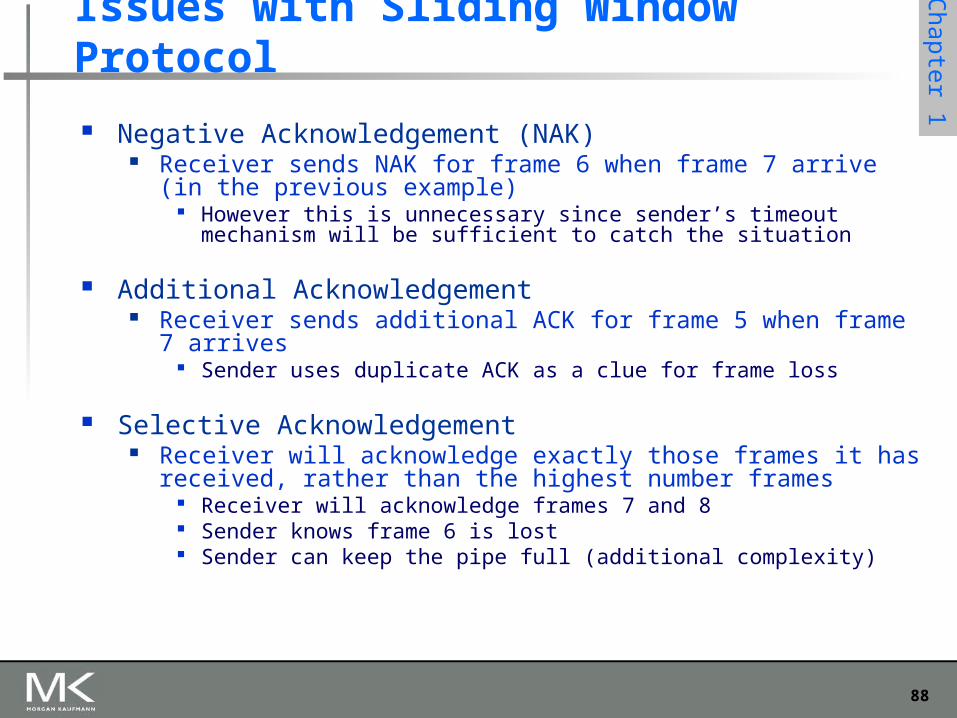
Negative Acknowledgement (NAK) Receiver sends NAK for frame 6 when frame 7 arrive (in the previous
example) However this is unnecessary since sender’s timeout mechanism will be
sufficient to catch the situation
Additional Acknowledgement Receiver sends additional ACK for frame 5 when frame 7 arrives
Sender uses duplicate ACK as a clue for frame loss
Selective Acknowledgement Receiver will acknowledge exactly those frames it has received, rather
than the highest number frames Receiver will acknowledge frames 7 and 8 Sender knows frame 6 is lost Sender can keep the pipe full (additional complexity)
89
Chapter 1
Issues with Sliding Window Protocol
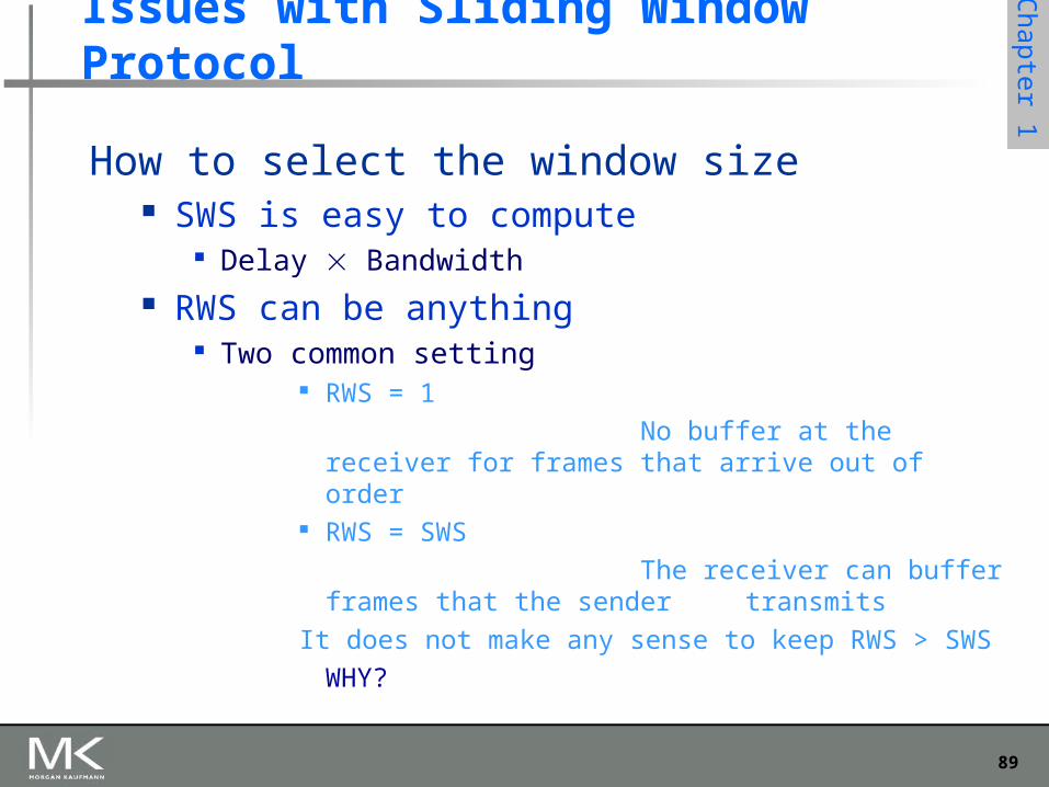
How to select the window size SWS is easy to compute
Delay Bandwidth RWS can be anything
Two common setting RWS = 1
No buffer at the receiver for frames that arrive out of order
RWS = SWS
The receiver can buffer frames that the sender transmits
It does not make any sense to keep RWS > SWS
WHY?
90
Chapter 1
Ethernet Most successful local area networking technology of last
20 years. Developed in the mid-1970s by researchers at the Xerox
Palo Alto Research Centers (PARC). Uses CSMA/CD technology
Carrier Sense Multiple Access with Collision Detection. A set of nodes send and receive frames over a shared link. Carrier sense means that all nodes can distinguish between an
idle and a busy link. Collision detection means that a node listens as it transmits and
can therefore detect when a frame it is transmitting has collided with a frame transmitted by another node.
91
Chapter 1
Ethernet Uses ALOHA (packet radio network) as the root protocol
Developed at the University of Hawaii to support communication across the Hawaiian Islands.
For ALOHA the medium was atmosphere, for Ethernet the medium is a coax cable.
DEC and Intel joined Xerox to define a 10-Mbps Ethernet standard in 1978.
This standard formed the basis for IEEE standard 802.3 More recently 802.3 has been extended to include a 100-
Mbps version called Fast Ethernet and a 1000-Mbps
version called Gigabit Ethernet.
92
Chapter 1
Ethernet An Ethernet segment is implemented on a coaxial cable of up
to 500 m. This cable is similar to the type used for cable TV except that it
typically has an impedance of 50 ohms instead of cable TV’s 75 ohms.
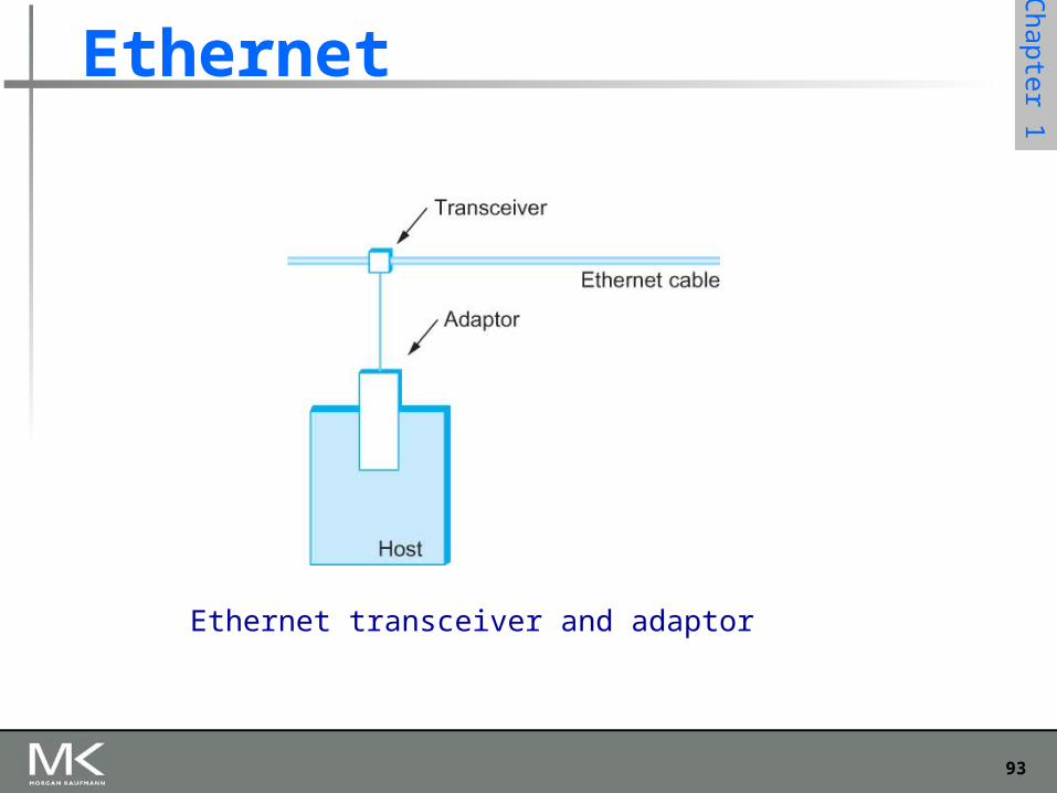
Hosts connect to an Ethernet segment by tapping into it. A transceiver (a small device directly attached to the tap)
detects when the line is idle and drives signal when the host is transmitting.
The transceiver also receives incoming signal. The transceiver is connected to an Ethernet adaptor which is
plugged into the host. The protocol is implemented on the adaptor.
93
Chapter 1
Ethernet
Ethernet transceiver and adaptor
94
Chapter 1
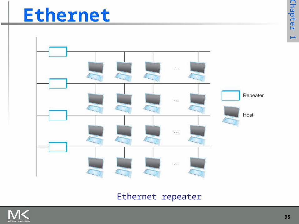
Ethernet Multiple Ethernet segments can be joined together by
repeaters. A repeater is a device that forwards digital signals. No more than four repeaters may be positioned between
any pair of hosts. An Ethernet has a total reach of only 2500 m.
95
Chapter 1
Ethernet
Ethernet repeater
96
Chapter 1
Ethernet Any signal placed on the Ethernet by a host is
broadcast over the entire network Signal is propagated in both directions. Repeaters forward the signal on all outgoing
segments. Terminators attached to the end of each segment
absorb the signal.
Ethernet uses Manchester encoding scheme.
97
Chapter 1
Ethernet New Technologies in Ethernet
Instead of using coax cable, an Ethernet can be constructed from a thinner cable known as 10Base2 (the original was 10Base5)
10 means the network operates at 10 Mbps Base means the cable is used in a baseband system 2 means that a given segment can be no longer than 200 m
98
Chapter 1
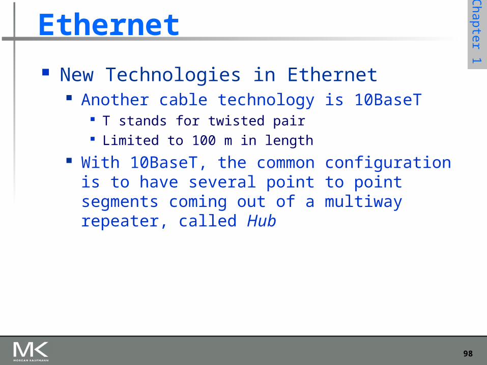
Ethernet New Technologies in Ethernet
Another cable technology is 10BaseT T stands for twisted pair Limited to 100 m in length
With 10BaseT, the common configuration is to have several point to point segments coming out of a multiway repeater, called Hub
99
Chapter 1
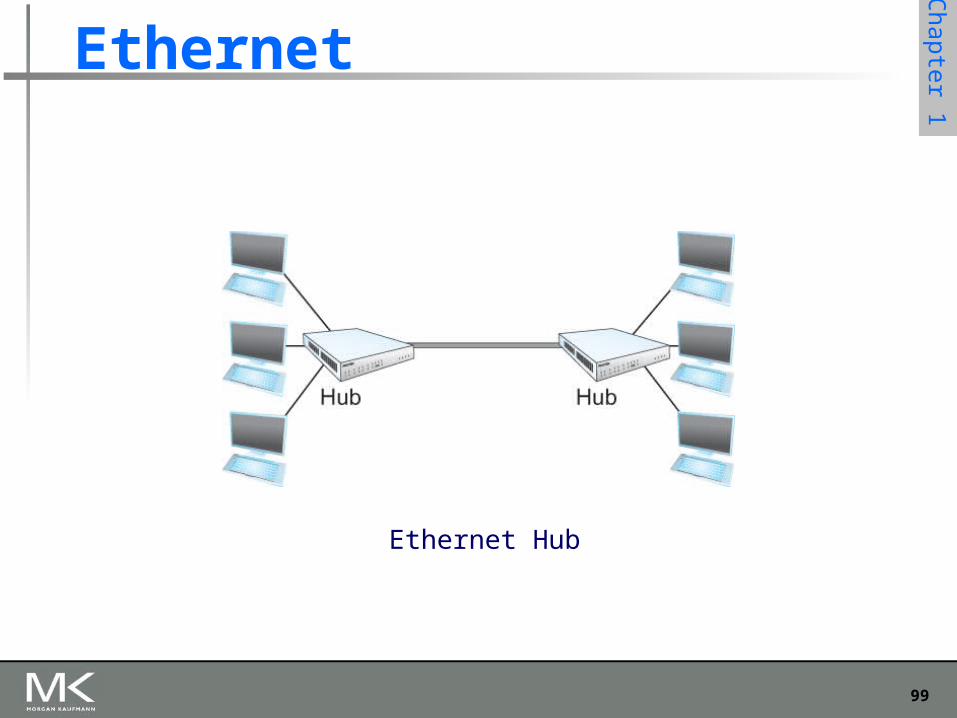
Ethernet
Ethernet Hub
100
Chapter 1
Access Protocol for Ethernet The algorithm is commonly called Ethernet’s Media
Access Control (MAC). It is implemented in Hardware on the network adaptor.
Frame format Preamble (64bit): allows the receiver to synchronize with the
signal (sequence of alternating 0s and 1s). Host and Destination Address (48bit each). Packet type (16bit): acts as demux key to identify the higher level
protocol. Data (up to 1500 bytes)
Minimally a frame must contain at least 46 bytes of data. Frame must be long enough to detect collision.
CRC (32bit)
101
Chapter 1
Ethernet Frame
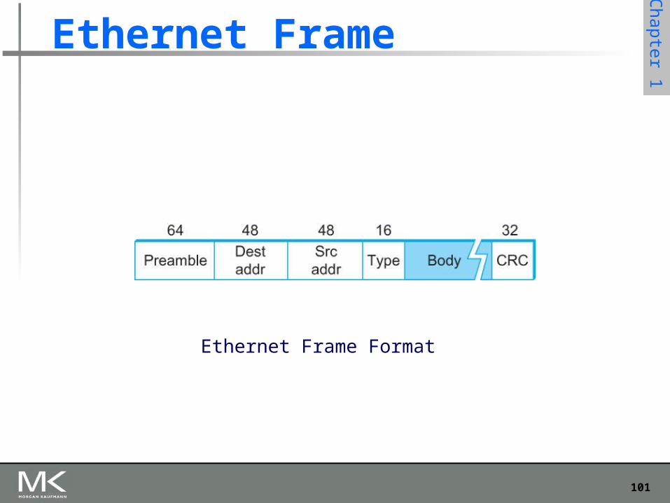
Ethernet Frame Format
102
Chapter 1
Copyright © 2010, Elsevier Inc. All rights Reserved
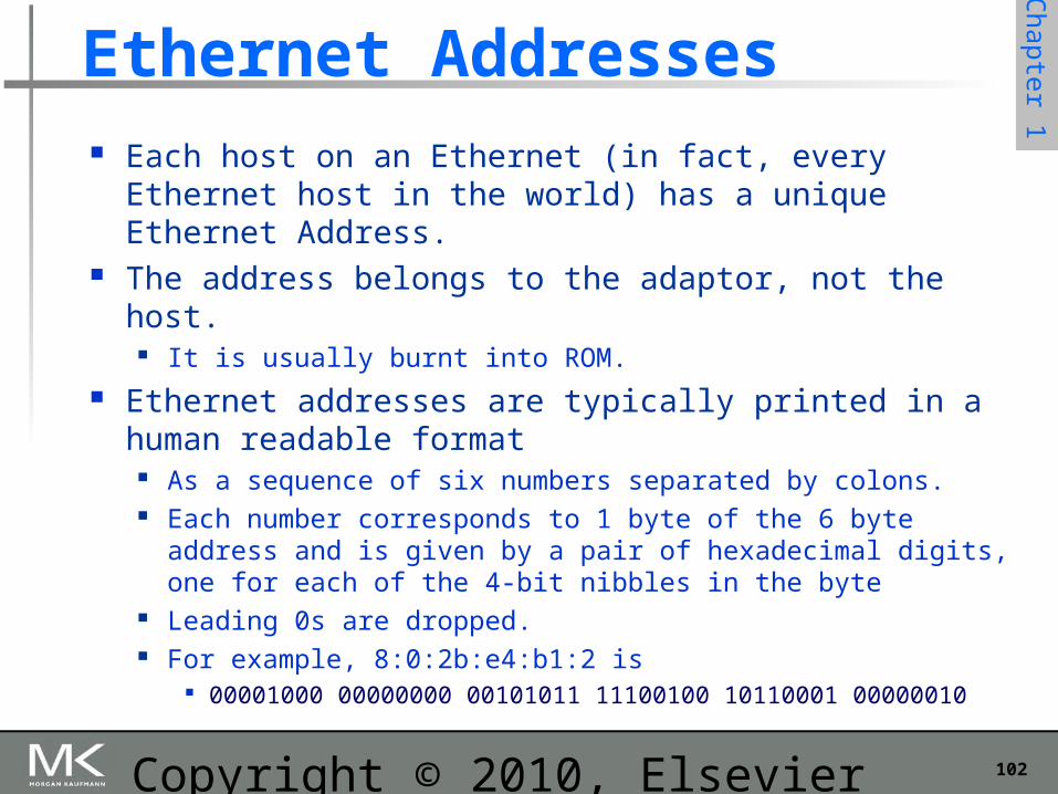
Ethernet Addresses Each host on an Ethernet (in fact, every Ethernet host in
the world) has a unique Ethernet Address. The address belongs to the adaptor, not the host.
It is usually burnt into ROM. Ethernet addresses are typically printed in a human
readable format As a sequence of six numbers separated by colons. Each number corresponds to 1 byte of the 6 byte address and is
given by a pair of hexadecimal digits, one for each of the 4-bit nibbles in the byte
Leading 0s are dropped. For example, 8:0:2b:e4:b1:2 is
00001000 00000000 00101011 11100100 10110001 00000010
103
Chapter 1
Ethernet Addresses To ensure that every adaptor gets a unique address,
each manufacturer of Ethernet devices is allocated a different prefix that must be prepended to the address on every adaptor they build
AMD has been assigned the 24bit prefix 8:0:20
104
Chapter 1
Ethernet Transmitter Algorithm
When the adaptor has a frame to send and the line is idle, it transmits the frame immediately.
The upper bound of 1500 bytes in the message means that the adaptor can occupy the line for a fixed length of time.
When the adaptor has a frame to send and the line is busy, it waits for the line to go idle and then transmits immediately.
The Ethernet is said to be 1-persistent protocol because an adaptor with a frame to send transmits with probability 1 whenever a busy line goes idle.
105
Chapter 1
Ethernet Transmitter Algorithm
Since there is no centralized control it is possible for two (or more) adaptors to begin transmitting at the same time,
Either because both found the line to be idle, Or, both had been waiting for a busy line to become idle.
When this happens, the two (or more) frames are said to be collide on the network.
106
Chapter 1
Ethernet Transmitter Algorithm
Since Ethernet supports collision detection, each sender is able to determine that a collision is in progress.
At the moment an adaptor detects that its frame is colliding with another, it first makes sure to transmit a 32-bit jamming sequence and then stops transmission.
Thus, a transmitter will minimally send 96 bits in the case of collision
64-bit preamble + 32-bit jamming sequence
107
Chapter 1
Ethernet Transmitter Algorithm
One way that an adaptor will send only 96 bit (called a runt frame) is if the two hosts are close to each other.
Had they been farther apart, They would have had to transmit longer, and thus send more
bits, before detecting the collision.
108
Chapter 1
Copyright © 2010, Elsevier Inc. All rights Reserved
Experience with Ethernet
Ethernets work best under lightly loaded conditions. Under heavy loads, too much of the network’s capacity is wasted
by collisions. Most Ethernets are used in a conservative way.
Have fewer than 200 hosts connected to them which is far fewer than the maximum of 1024.
Most Ethernets are far shorter than 2500m with a round-trip delay of closer to 5 s than 51.2 s.
Ethernets are easy to administer and maintain. There are no switches that can fail and no routing and
configuration tables that have to be kept up-to-date. It is easy to add a new host to the network. It is inexpensive.
Cable is cheap, and only other cost is the network adaptor on each host.
109
Chapter 1
Wireless Links
Wireless links transmit electromagnetic signals Radio, microwave, infrared
Wireless links all share the same “wire” (so to speak) The challenge is to share it efficiently without unduly interfering
with each other Most of this sharing is accomplished by dividing the “wire” along
the dimensions of frequency and space Exclusive use of a particular frequency in a particular
geographic area may be allocated to an individual entity such as a corporation
110
Chapter 1
Wireless Links
These allocations are determined by government agencies such as FCC (Federal Communications Commission) in USA
Specific bands (frequency) ranges are allocated to certain uses.
Some bands are reserved for government use Other bands are reserved for uses such as AM radio, FM radio,
televisions, satellite communications, and cell phones Specific frequencies within these bands are then allocated to
individual organizations for use within certain geographical areas.
Finally, there are several frequency bands set aside for “license exempt” usage
Bands in which a license is not needed
111
Chapter 1
Wireless Links
Devices that use license-exempt frequencies are still subject to certain restrictions
The first is a limit on transmission power This limits the range of signal, making it less likely to interfere
with another signal For example, a cordless phone might have a range of about 100 feet.
112
Chapter 1
Wireless Links
The second restriction requires the use of Spread Spectrum technique
Idea is to spread the signal over a wider frequency band So as to minimize the impact of interference from other devices Originally designed for military use
Frequency hopping Transmitting signal over a random sequence of frequencies
- First transmitting at one frequency, then a second, then a third…- The sequence of frequencies is not truly random, instead computed
algorithmically by a pseudorandom number generator- The receiver uses the same algorithm as the sender, initializes it with the same
seed, and is- Able to hop frequencies in sync with the transmitter to correctly receive the frame
113
Chapter 1
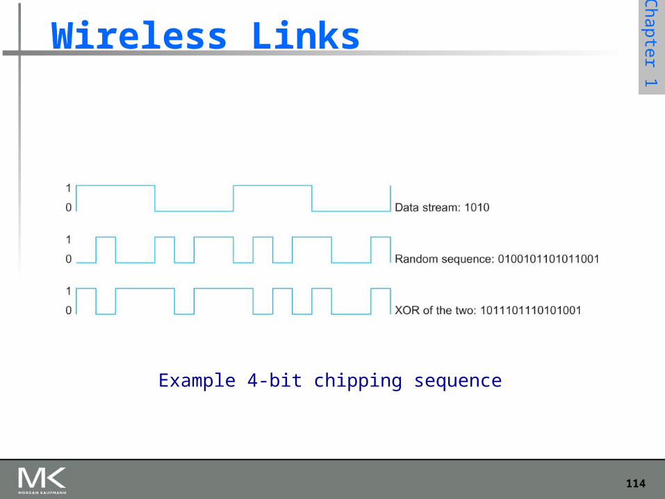
Wireless Links
A second spread spectrum technique called Direct sequence
Represents each bit in the frame by multiple bits in the transmitted signal.
For each bit the sender wants to transmit It actually sends the exclusive OR of that bit and n random bits
The sequence of random bits is generated by a pseudorandom number generator known to both the sender and the receiver.
The transmitted values, known as an n-bit chipping code, spread the signal across a frequency band that is n times wider
114
Chapter 1
Wireless Links
Example 4-bit chipping sequence

115
Chapter 1
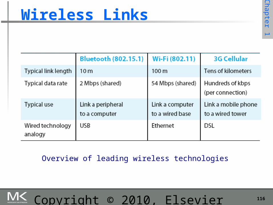
Wireless Links
Wireless technologies differ in a variety of dimensions How much bandwidth they provide How far apart the communication nodes can be
Four prominent wireless technologies Bluetooth Wi-Fi (more formally known as 802.11) WiMAX (802.16) 3G cellular wireless
116
Chapter 1
Copyright © 2010, Elsevier Inc. All rights Reserved
Wireless Links
Overview of leading wireless technologies
117
Chapter 1
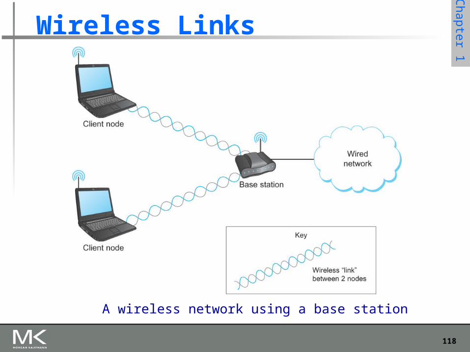
Wireless Links
Mostly widely used wireless links today are usually asymmetric
Two end-points are usually different kinds of nodes One end-point usually has no mobility, but has wired connection to the
Internet (known as base station) The node at the other end of the link is often mobile
118
Chapter 1
Wireless Links
A wireless network using a base station
119
Chapter 1
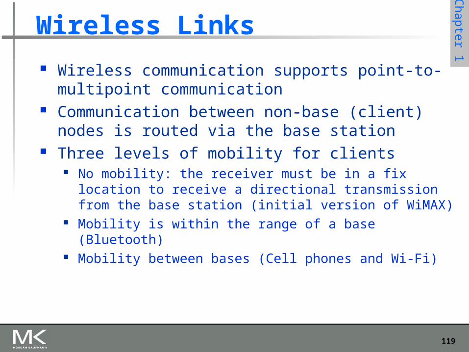
Wireless Links
Wireless communication supports point-to-multipoint communication
Communication between non-base (client) nodes is routed via the base station
Three levels of mobility for clients No mobility: the receiver must be in a fix location to receive a
directional transmission from the base station (initial version of WiMAX)
Mobility is within the range of a base (Bluetooth) Mobility between bases (Cell phones and Wi-Fi)
120
Chapter 1
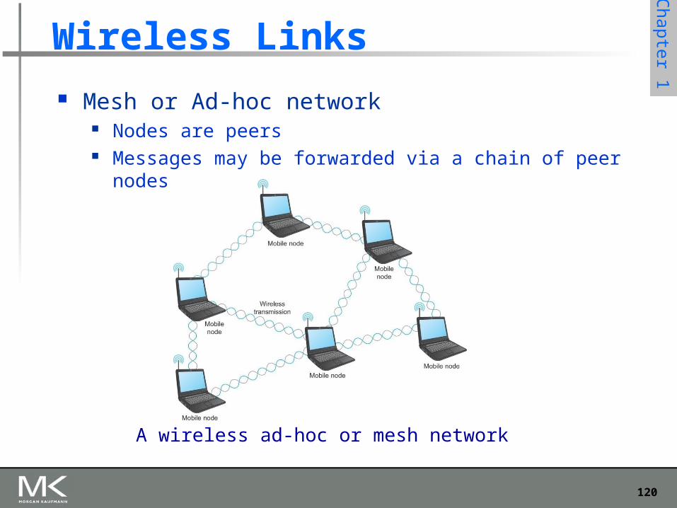
Wireless Links
Mesh or Ad-hoc network Nodes are peers Messages may be forwarded via a chain of peer nodes
A wireless ad-hoc or mesh network
121
Chapter 1
IEEE 802.11
Also known as Wi-Fi Like its Ethernet and token ring siblings, 802.11 is
designed for use in a limited geographical area (homes, office buildings, campuses)
Primary challenge is to mediate access to a shared communication medium – in this case, signals propagating through space
802.11 supports additional features power management and security mechanisms
122
Chapter 1
Copyright © 2010, Elsevier Inc. All rights Reserved
IEEE 802.11 Original 802.11 standard defined two radio-based physical layer
standard One using the frequency hopping
Over 79 1-MHz-wide frequency bandwidths Second using direct sequence
Using 11-bit chipping sequence Both standards run in the 2.4-GHz and provide up to 2 Mbps
Then physical layer standard 802.11b was added Using a variant of direct sequence 802.11b provides up to 11 Mbps Uses license-exempt 2.4-GHz band
Then came 802.11a which delivers up to 54 Mbps using OFDM 802.11a runs on license-exempt 5-GHz band
Most recent standard is 802.11g which is backward compatible with 802.11b
Uses 2.4 GHz band, OFDM and delivers up to 54 Mbps
123
Chapter 1
IEEE 802.11 – Collision Avoidance
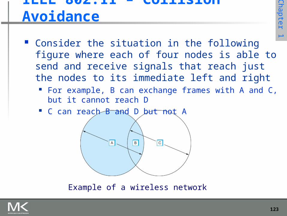
Consider the situation in the following figure where each of four nodes is able to send and receive signals that reach just the nodes to its immediate left and right
For example, B can exchange frames with A and C, but it cannot reach D
C can reach B and D but not A
Example of a wireless network
124
Chapter 1
IEEE 802.11 – Collision Avoidance
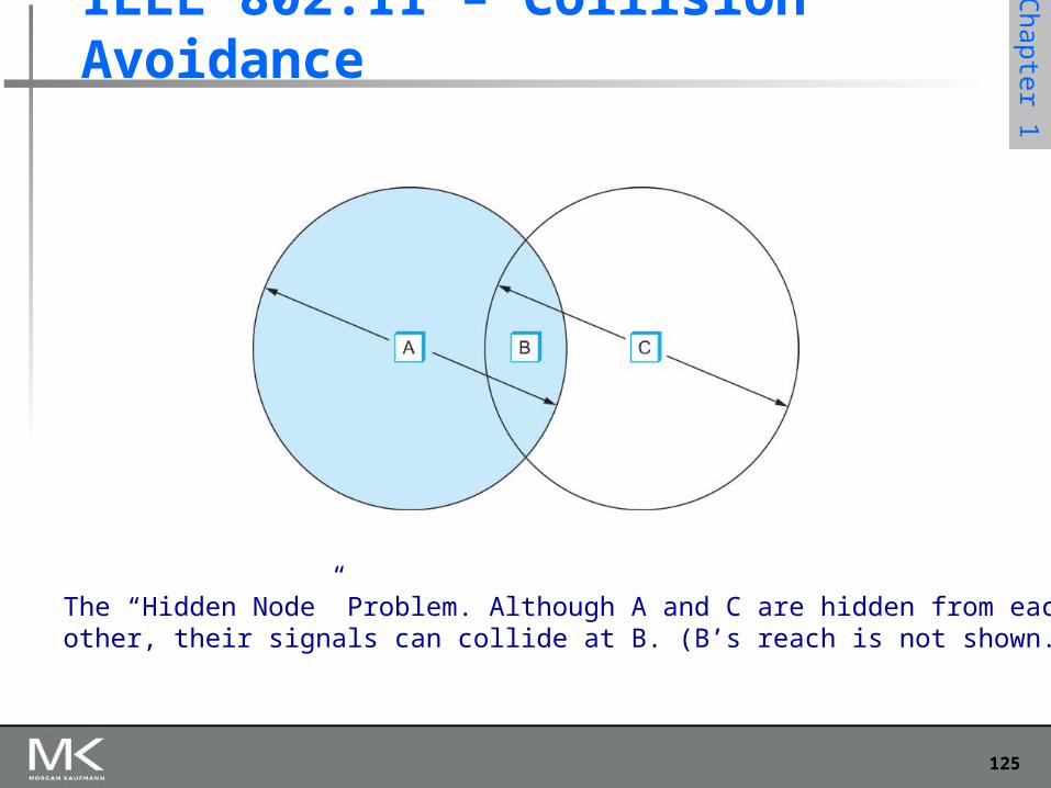
Suppose both A and C want to communicate with B and so they each send it a frame.
A and C are unaware of each other since their signals do not carry that far
These two frames collide with each other at B But unlike an Ethernet, neither A nor C is aware of this collision
A and C are said to hidden nodes with respect to each other
125
Chapter 1
IEEE 802.11 – Collision Avoidance
The “Hidden Node” Problem. Although A and C are hidden from eachother, their signals can collide at B. (B’s reach is not shown.)
126
Chapter 1
IEEE 802.11 – Collision Avoidance
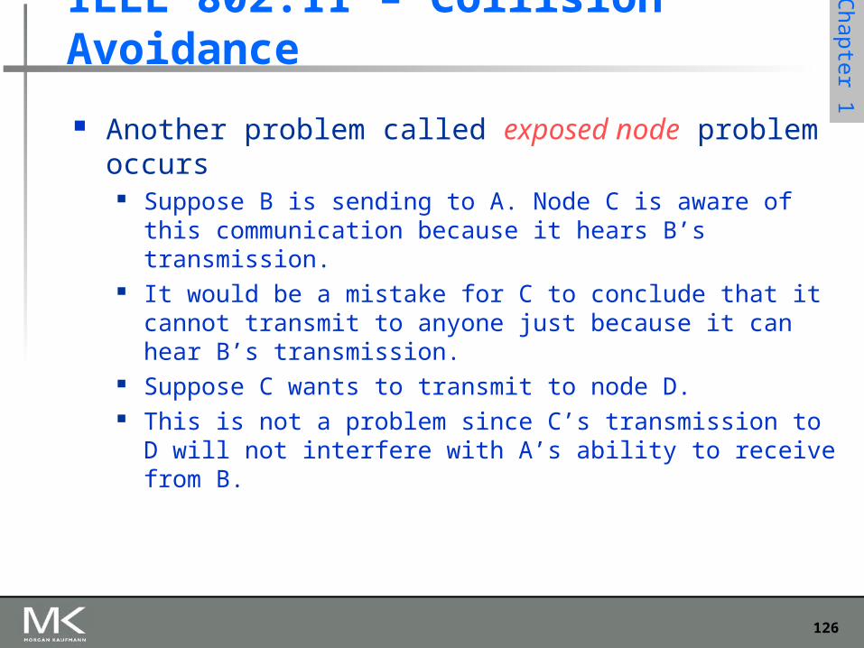
Another problem called exposed node problem occurs Suppose B is sending to A. Node C is aware of this
communication because it hears B’s transmission. It would be a mistake for C to conclude that it cannot transmit to
anyone just because it can hear B’s transmission. Suppose C wants to transmit to node D. This is not a problem since C’s transmission to D will not
interfere with A’s ability to receive from B.
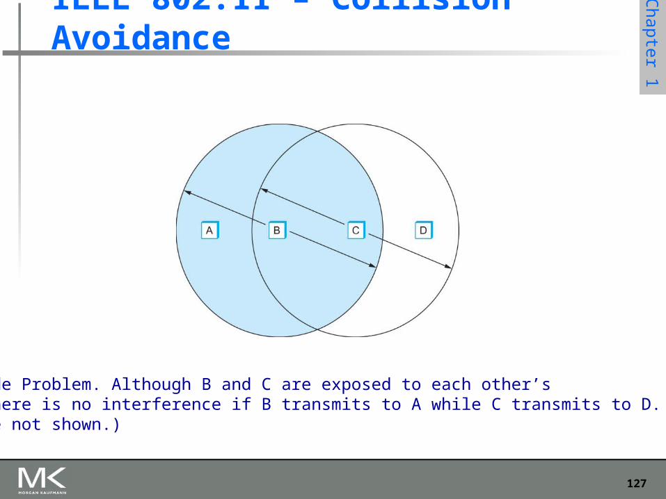
127
Chapter 1
IEEE 802.11 – Collision Avoidance
Exposed Node Problem. Although B and C are exposed to each other’ssignals, there is no interference if B transmits to A while C transmits to D. (A and D’sreaches are not shown.)
128
Chapter 1
IEEE 802.11 – Collision Avoidance
802.11 addresses these two problems with an algorithm called Multiple Access with Collision Avoidance (MACA).
Key Idea Sender and receiver exchange control frames with each other
before the sender actually transmits any data. This exchange informs all nearby nodes that a transmission is
about to begin Sender transmits a Request to Send (RTS) frame to the receiver.
The RTS frame includes a field that indicates how long the sender wants to hold the medium
- Length of the data frame to be transmitted
Receiver replies with a Clear to Send (CTS) frame This frame echoes this length field back to the sender
129
Chapter 1
IEEE 802.11 – Collision Avoidance
Any node that sees the CTS frame knows that it is close to the receiver, therefore cannot transmit for the period of time it takes to send a frame of
the specified length Any node that sees the RTS frame but not the CTS
frame is not close enough to the receiver to interfere with it, and so is free to transmit
130
Chapter 1
Copyright © 2010, Elsevier Inc. All rights Reserved
IEEE 802.11 – Collision Avoidance
Using ACK in MACA Proposed in MACAW: MACA for Wireless LANs
Receiver sends an ACK to the sender after successfully receiving a frame
All nodes must wait for this ACK before trying to transmit If two or more nodes detect an idle link and try to
transmit an RTS frame at the same time Their RTS frame will collide with each other
802.11 does not support collision detection So the senders realize the collision has happened when they do
not receive the CTS frame after a period of time In this case, they each wait a random amount of time before
trying again. The amount of time a given node delays is defined by the same
exponential backoff algorithm used on the Ethernet.
131
Chapter 1
Copyright © 2010, Elsevier Inc. All rights Reserved
IEEE 802.11 – Distribution System
802.11 is suitable for an ad-hoc configuration of nodes that may or may not be able to communicate with all other nodes.
Nodes are free to move around The set of directly reachable nodes may change over
time To deal with this mobility and partial connectivity,
802.11 defines additional structures on a set of nodes Instead of all nodes being created equal,
some nodes are allowed to roam some are connected to a wired network infrastructure
- they are called Access Points (AP) and they are connected to each other by a so-called distribution system
132
Chapter 1
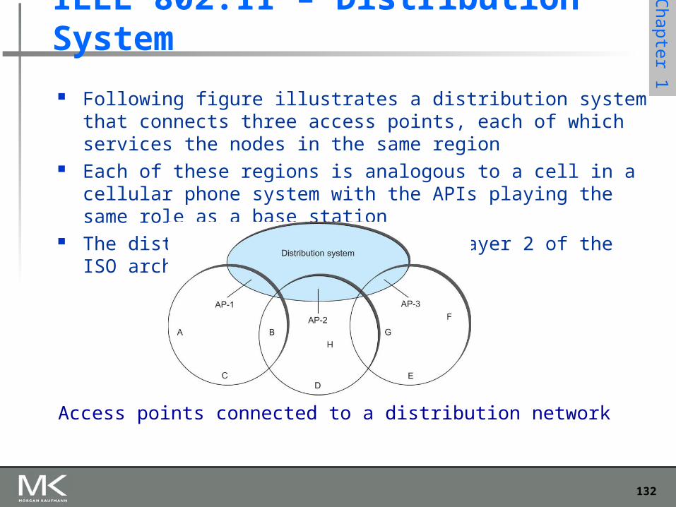
Following figure illustrates a distribution system that connects three access points, each of which services the nodes in the same region
Each of these regions is analogous to a cell in a cellular phone system with the APIs playing the same role as a base station
The distribution network runs at layer 2 of the ISO architecture
IEEE 802.11 – Distribution System
Access points connected to a distribution network
133
Chapter 1
IEEE 802.11 – Distribution System
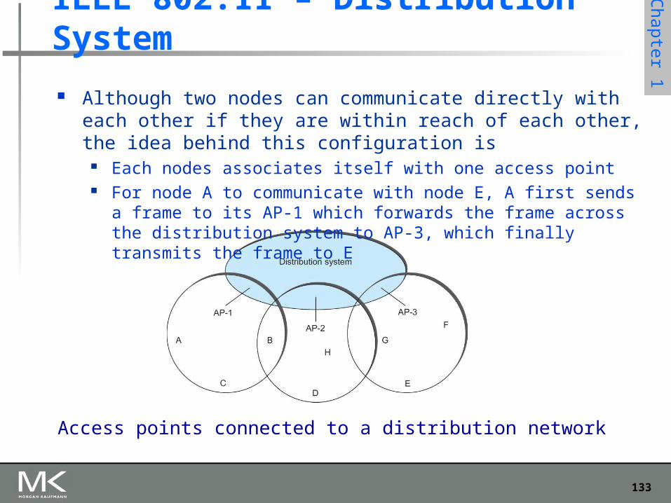
Although two nodes can communicate directly with each other if they are within reach of each other, the idea behind this configuration is
Each nodes associates itself with one access point For node A to communicate with node E, A first sends a frame to its AP-
1 which forwards the frame across the distribution system to AP-3, which finally transmits the frame to E
Access points connected to a distribution network
134
Chapter 1
Copyright © 2010, Elsevier Inc. All rights Reserved
IEEE 802.11 – Distribution System
How do the nodes select their access points How does it work when nodes move from one cell to another
The technique for selecting an AP is called scanning The node sends a Probe frame All APs within reach reply with a Probe Response frame The node selects one of the access points and sends that AP an
Association Request frame The AP replies with an Association Response frame
A node engages this protocol whenever it joins the network, as well as when it becomes unhappy with its current AP
This might happen, for example, because the signal from its current AP has weakened due to the node moving away from it
Whenever a node acquires a new AP, the new AP notifies the old AP of the change via the distribution system
135
Chapter 1
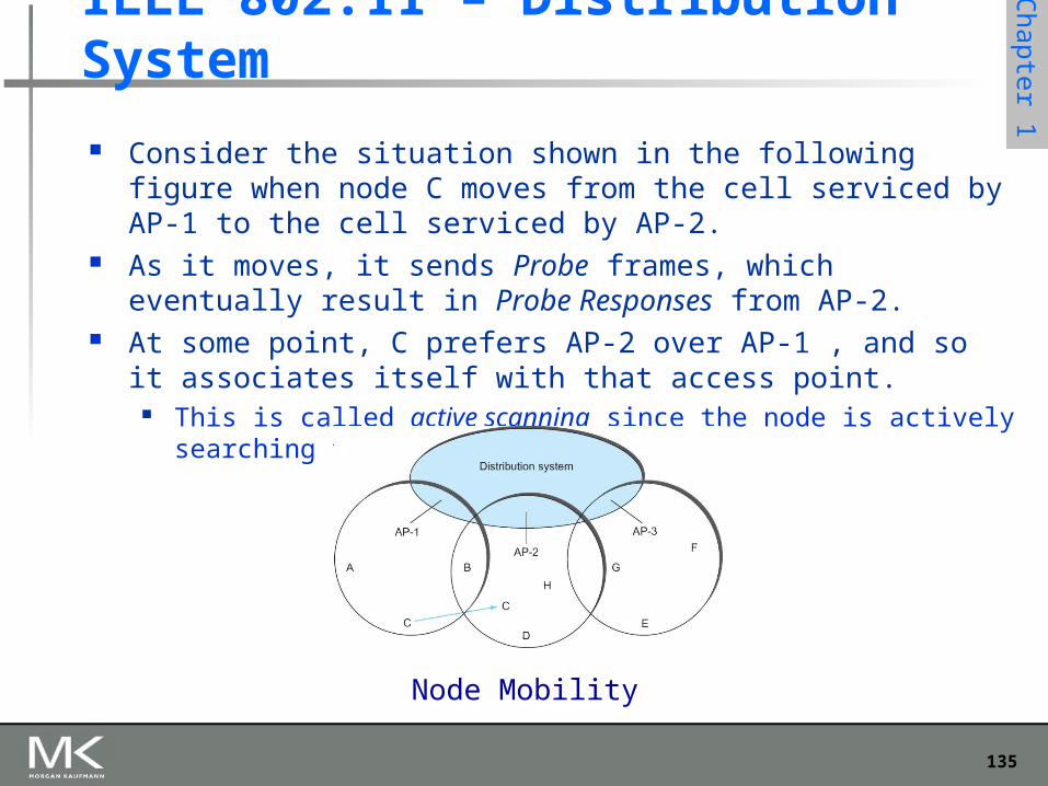
Consider the situation shown in the following figure when node C moves from the cell serviced by AP-1 to the cell serviced by AP-2.
As it moves, it sends Probe frames, which eventually result in Probe Responses from AP-2.
At some point, C prefers AP-2 over AP-1 , and so it associates itself with that access point.
This is called active scanning since the node is actively searching for an access point
IEEE 802.11 – Distribution System
Node Mobility
136
Chapter 1
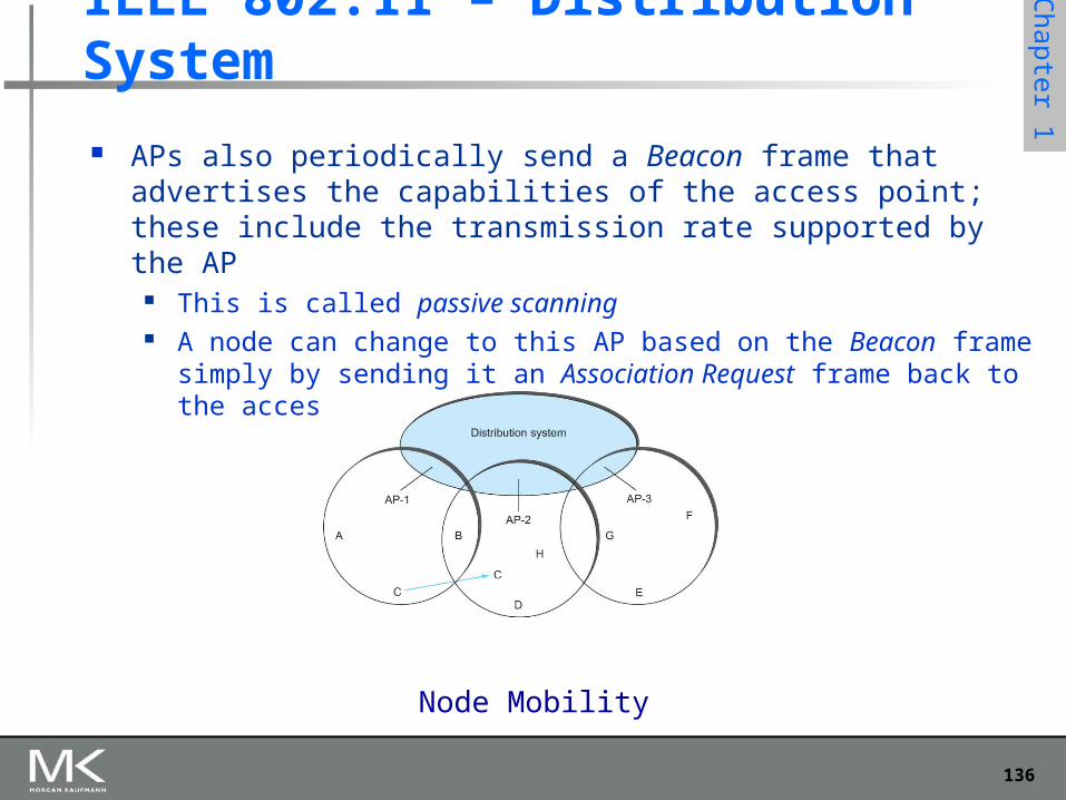
IEEE 802.11 – Distribution System
APs also periodically send a Beacon frame that advertises the capabilities of the access point; these include the transmission rate supported by the AP
This is called passive scanning A node can change to this AP based on the Beacon frame simply by
sending it an Association Request frame back to the access point.
Node Mobility
137
Chapter 1
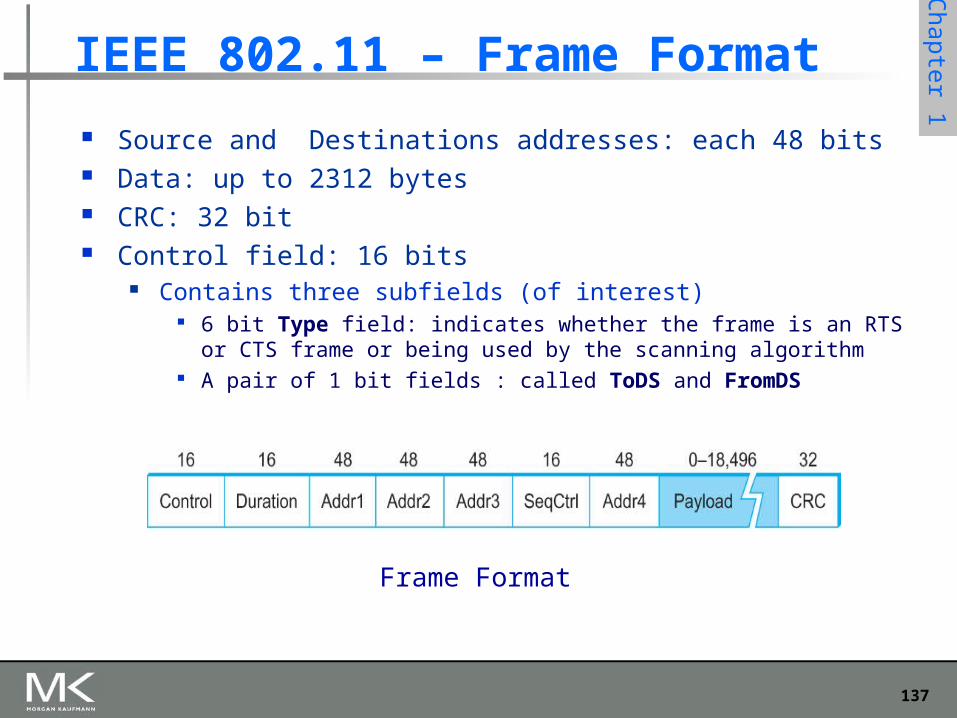
IEEE 802.11 – Frame Format
Source and Destinations addresses: each 48 bits Data: up to 2312 bytes CRC: 32 bit Control field: 16 bits
Contains three subfields (of interest) 6 bit Type field: indicates whether the frame is an RTS or CTS frame or
being used by the scanning algorithm A pair of 1 bit fields : called ToDS and FromDS
Frame Format
138
Chapter 1
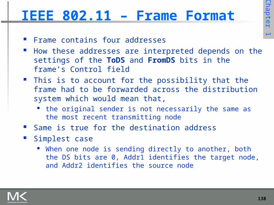
IEEE 802.11 – Frame Format
Frame contains four addresses How these addresses are interpreted depends on the settings of the
ToDS and FromDS bits in the frame’s Control field This is to account for the possibility that the frame had to be
forwarded across the distribution system which would mean that, the original sender is not necessarily the same as the most recent
transmitting node Same is true for the destination address Simplest case
When one node is sending directly to another, both the DS bits are 0, Addr1 identifies the target node, and Addr2 identifies the source node
139
Chapter 1
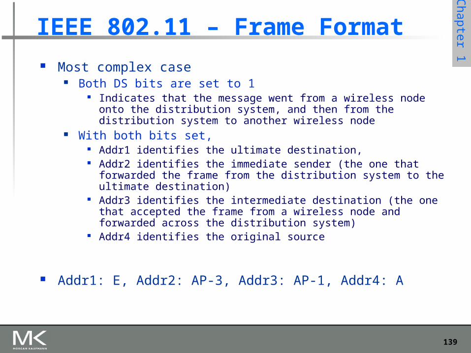
IEEE 802.11 – Frame Format
Most complex case Both DS bits are set to 1
Indicates that the message went from a wireless node onto the distribution system, and then from the distribution system to another wireless node
With both bits set, Addr1 identifies the ultimate destination, Addr2 identifies the immediate sender (the one that forwarded the frame from
the distribution system to the ultimate destination) Addr3 identifies the intermediate destination (the one that accepted the frame
from a wireless node and forwarded across the distribution system) Addr4 identifies the original source
Addr1: E, Addr2: AP-3, Addr3: AP-1, Addr4: A
140
Chapter 1
Bluetooth
Used for very short range communication between mobile phones, PDAs, notebook computers and other personal or peripheral devices
Operates in the license-exempt band at 2.45 GHz Has a range of only 10 m Communication devices typically belong to one individual
or group Sometimes categorized as Personal Area Network (PAN)
Version 2.0 provides speeds up to 2.1 Mbps Power consumption is low
141
Chapter 1
Copyright © 2010, Elsevier Inc. All rights Reserved
Bluetooth Bluetooth is specified by an industry consortium called
the Bluetooth Special Interest Group It specifies an entire suite of protocols, going beyond the
link layer to define application protocols, which it calls profiles, for a range of applications
There is a profile for synchronizing a PDA with personal computer
Another profile gives a mobile computer access to a wired LAN The basic Bluetooth network configuration is called a
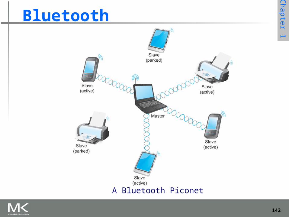
piconet Consists of a master device and up to seven slave devices Any communication is between the master and a slave The slaves do not communicate directly with each other A slave can be parked: set to an inactive, low-power state
142
Chapter 1
Bluetooth
A Bluetooth Piconet
143
Chapter 1
ZigBee ZigBee is a new technology that competes with Bluetooth Devised by the ZigBee alliance and standardized as
IEEE 802.15.4 It is designed for situations where the bandwidth
requirements are low and power consumption must be very low to give very long battery life
It is also intended to be simpler and cheaper than Bluetooth, making it financially feasible to incorporate in cheaper devices such as a wall switch that wirelessly communicates with a ceiling-mounted fan
144
Chapter 1
Introduction 1-144
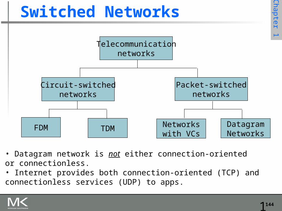
Switched Networks
Telecommunicationnetworks
Circuit-switchednetworks
FDM TDM
Packet-switchednetworks
Networkswith VCs
DatagramNetworks
• Datagram network is not either connection-oriented or connectionless.• Internet provides both connection-oriented (TCP) and connectionless services (UDP) to apps.
145
Chapter 1
Introduction 1-145
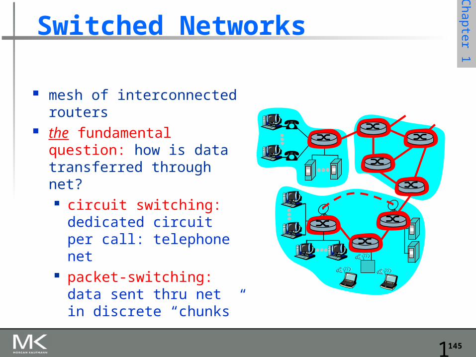
Switched Networks
mesh of interconnected routers
the fundamental question: how is data transferred through net? circuit switching:
dedicated circuit per call: telephone net
packet-switching: data sent thru net in discrete “chunks”
146
Chapter 1
Introduction 1-146
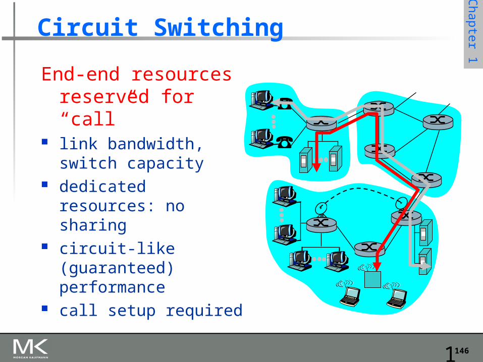
Circuit Switching
End-end resources reserved for “call”
link bandwidth, switch capacity
dedicated resources: no sharing
circuit-like (guaranteed) performance
call setup required
147
Chapter 1
Introduction 1-147
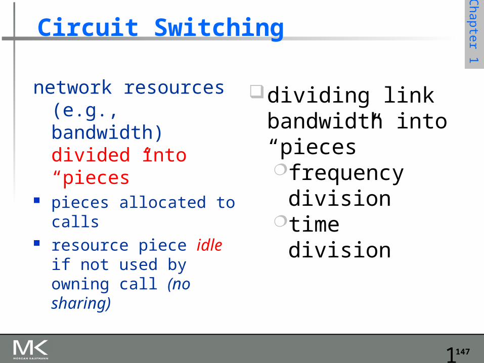
Circuit Switching
network resources (e.g., bandwidth) divided into “pieces”
pieces allocated to calls resource piece idle if not
used by owning call (no sharing)
dividing link bandwidth into “pieces”frequency
divisiontime division
148
Chapter 1
Introduction 1-148
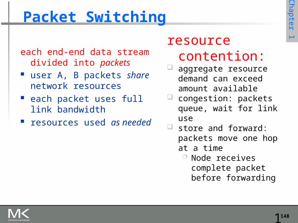
Packet Switching
each end-end data stream divided into packets
user A, B packets share network resources
each packet uses full link bandwidth
resources used as needed
resource contention:
aggregate resource demand can exceed amount available
congestion: packets queue, wait for link use
store and forward: packets move one hop at a time Node receives
complete packet before forwarding
149
Chapter 1
Introduction 1-149
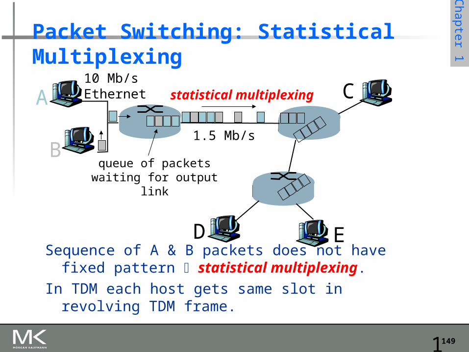
Packet Switching: Statistical Multiplexing
Sequence of A & B packets does not have fixed pattern statistical multiplexing.
In TDM each host gets same slot in revolving TDM frame.
A
B
C10 Mb/sEthernet
1.5 Mb/s
D E
statistical multiplexing
queue of packetswaiting for output
link
150
Chapter 1
Introduction 1-150
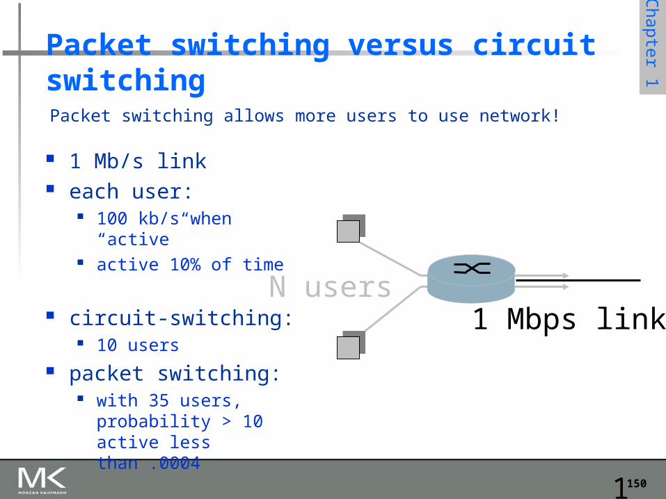
Packet switching versus circuit switching
1 Mb/s link each user:
100 kb/s when “active” active 10% of time
circuit-switching: 10 users
packet switching: with 35 users, probability
> 10 active less than .0004
Packet switching allows more users to use network!
N users1 Mbps link
151
Chapter 1
Introduction 1-151
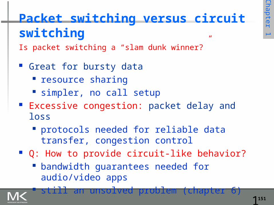
Packet switching versus circuit switching
Great for bursty data resource sharing simpler, no call setup
Excessive congestion: packet delay and loss protocols needed for reliable data transfer,
congestion control Q: How to provide circuit-like behavior?
bandwidth guarantees needed for audio/video apps still an unsolved problem (chapter 6)
Is packet switching a “slam dunk winner?”
152
Chapter 1
Introduction 1-152
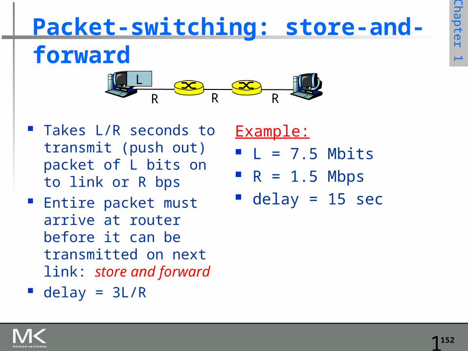
Packet-switching: store-and-forward
Takes L/R seconds to transmit (push out) packet of L bits on to link or R bps
Entire packet must arrive at router before it can be transmitted on next link: store and forward
delay = 3L/R
Example: L = 7.5 Mbits R = 1.5 Mbps delay = 15 sec
R R RL
153
Chapter 1
Introduction 1-153
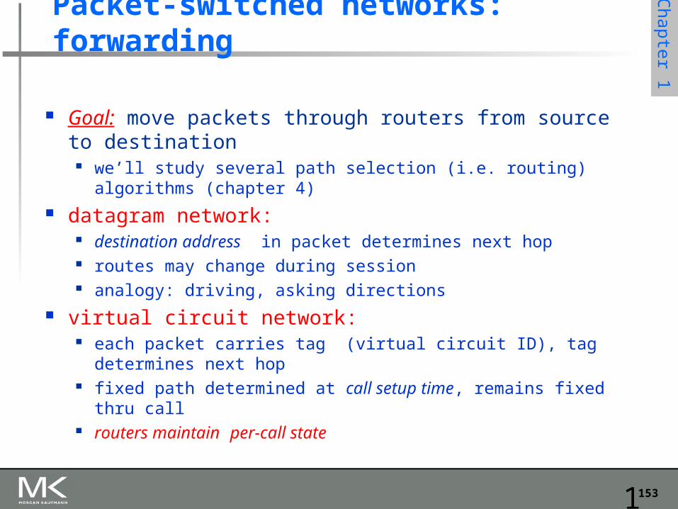
Packet-switched networks: forwarding
Goal: move packets through routers from source to destination
we’ll study several path selection (i.e. routing) algorithms (chapter 4)
datagram network: destination address in packet determines next hop routes may change during session analogy: driving, asking directions
virtual circuit network: each packet carries tag (virtual circuit ID), tag determines next
hop fixed path determined at call setup time, remains fixed thru call routers maintain per-call state
154
Chapter 1
Bridges and LAN Switches Bridges and LAN Switches
Class of switches that is used to forward packets between shared-media LANs such as Ethernets
Known as LAN switches Referred to as Bridges
Suppose you have a pair of Ethernets that you want to interconnect One approach is put a repeater in between them
It might exceed the physical limitation of the Ethernet No more than four repeaters between any pair of hosts No more than a total of 2500 m in length is allowed
An alternative would be to put a node between the two Ethernets and have the node forward frames from one Ethernet to the other
This node is called a Bridge A collection of LANs connected by one or more bridges is usually said to form an
Extended LAN
155
Chapter 1
Bridges and LAN Switches Simplest Strategy for Bridges
Accept LAN frames on their inputs and forward them out to all other outputs
Used by early bridges
Learning Bridges Observe that there is no need to forward all the frames that a bridge
receives
156
Chapter 1
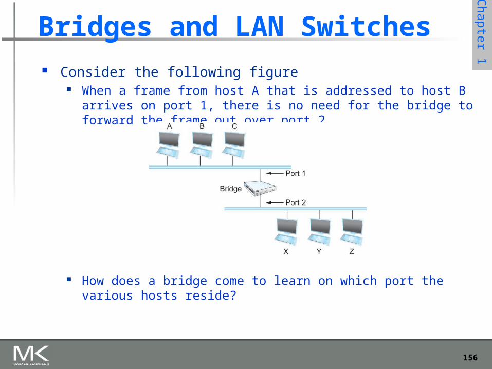
Consider the following figure When a frame from host A that is addressed to host B arrives on port 1,
there is no need for the bridge to forward the frame out over port 2.
How does a bridge come to learn on which port the various hosts reside?
Bridges and LAN Switches
157
Chapter 1
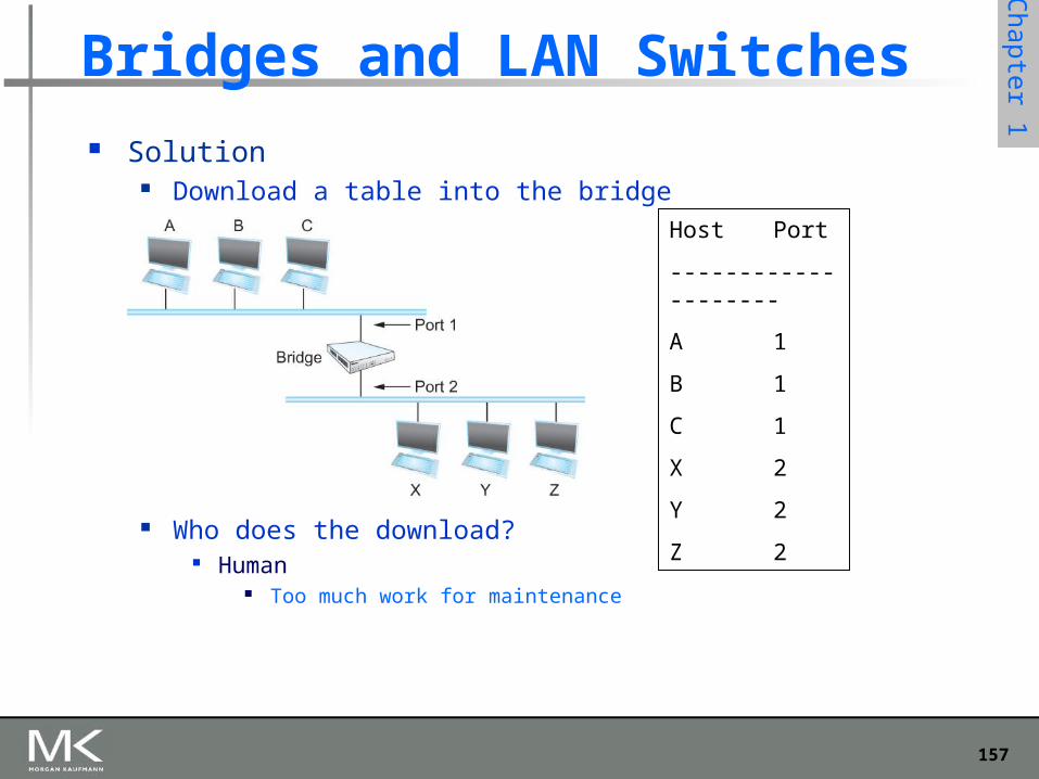
Bridges and LAN Switches Solution
Download a table into the bridge
Who does the download? Human
Too much work for maintenance
A
Bridge
B C
X Y Z
Port 1
Port 2
Host Port
--------------------
A 1
B 1
C 1
X 2
Y 2
Z 2
158
Chapter 1
Bridges and LAN Switches Can the bridge learn this information by itself?
Yes
How Each bridge inspects the source address in all the frames it receives Record the information at the bridge and build the table When a bridge first boots, this table is empty Entries are added over time A timeout is associated with each entry The bridge discards the entry after a specified period of time
To protect against the situation in which a host is moved from one network to another
If the bridge receives a frame that is addressed to host not currently in the table
Forward the frame out on all other ports
159
Chapter 1
Bridges and LAN Switches
Broadcast and Multicast Forward all broadcast/multicast frames
Current practice Learn when no group members downstream Accomplished by having each member of
group G send a frame to bridge multicast address with G in source field
160
Chapter 1
Bridges and LAN Switches
Limitation of Bridges Do not scale
Spanning tree algorithm does not scale Broadcast does not scale
Do not accommodate heterogeneity