1 Status of infrastructure MICE Collaboration Meeting, Frascati, June 26-29, 2005 Yury...
30
1 Status of infrastructure Status of infrastructure MICE Collaboration Meeting, Frascati, June 26-29, 2005 Yury Ivanyushenkov Applied Science Division, Engineering and Instrumentation Department RAL
-
Upload
job-harrell -
Category
Documents
-
view
217 -
download
0
description
3 MICE layout
Transcript of 1 Status of infrastructure MICE Collaboration Meeting, Frascati, June 26-29, 2005 Yury...

1
Status of infrastructureStatus of infrastructure
MICE Collaboration Meeting, Frascati, June 26-29, 2005
Yury Ivanyushenkov
Applied Science Division,Engineering and Instrumentation Department
RAL

2
• Layout
• Hydrogen system
• Shielding
• Support system
Scope
3
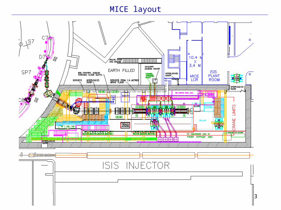
MICE layout

4
MICE phase I initial

5
MICE phase I final

6
Tchill
Pressuregauge
Non-return valveP P VP Vacuum pumpBursting diskPressure
relief valveValvePressureregulator
CoolantOut In
Test absorber assembly
Metal Hydride storage unit
(20m3 capacity)
Purge valve
0.5 bar
0.9 bar
H2 Detector
P
P
VP1
VP2
Purge valve
Chiller/Heater
Unit
1 bar
PP
0.5 bar
0.9 bar Helium supply
Hydrogen supply
High level vent
Buffer vessel
Vent outsideflame arrester
Extract hoodH2Detector
PP
Nitrogen supply
PP
PP
1 m3
Hydrogen zone 2
Vent manifold Vent manifold
P1
PV1
PV7
PV8
PV2
PV3
PV4
HV1
Fill valve
Tbed
HV2
HV3
P3
P
P2
PV6
High level vent
Non return valve
0.1 bar
Hydrogen system test rig
Mass spectrometer
M. F.M.
Mass flow meter
7
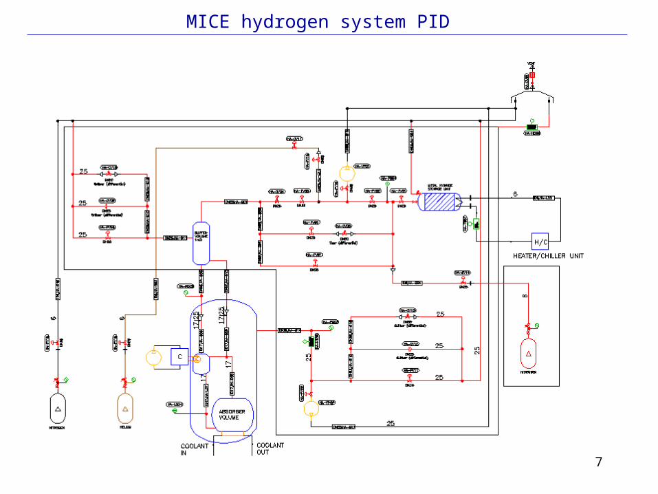
MICE hydrogen system PID

8
MICE hydrogen system layout: Principle
• Argon jacketing of pipework is proposed in outside the hood. Basic philosophy is shown below
Hood
MICE
Cabinet for hydride bed and pipework
H2sensorArgon Jacketing
Safety area
1m3

9
MICE hydrogen system layout (2)
10
• WP1 Initial design -> Internal safety review• WP2 Detailed design and procurement • WP3 Installation and commissioning • WP4 Test Programme
Hydrogen system R&D: Work packages
11
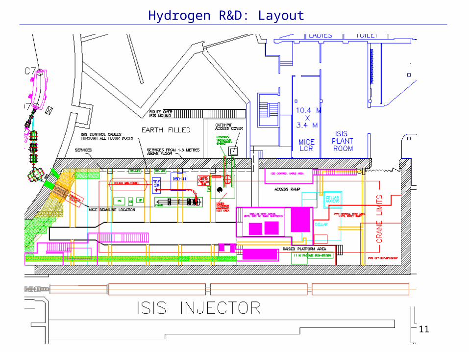
Hydrogen R&D: Layout

12
Hydrogen R&D: Layout (2)

13
Hydrogen test cryostat: Concept
T H
T H
• Instrumentation mimics what we will need on the absorber for the control system and interlocks
• Heater will regulate temperature of cryocooler – need redundancy and interlock with compressor
• Dia.Reservoir =height=290mm

14
Hydrogen Test Cryostat Outline
1120
Ø 580
15
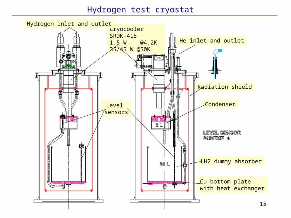
Hydrogen test cryostat
Condenser
LH2 dummy absorber
Level sensors
Cryocooler SRDK-4151.5 W @4.2K35/45 W @50K
Radiation shield
Hydrogen inlet and outlet
He inlet and outlet
Cu bottom plate with heat exchanger

16
Hydrogen test cryostat (2)
Cu bottom plate with heat exchanger
Cartridge heaters
Finned top plateof condenser

17
Outline Schedule•WP1 Initial design: May – August 05
with Review in September 05 •WP2 Detailed design and procurement: Aug 05 – Feb 06•WP3 Installation and commissioning: Jan – April 06•WP4 Test Programme: June – Oct 06
Hydrogen system R&D – Schedule
18
Radiation shielding
• No changes in the layout • Paul is working toward a much more reasonable (and cost effective) shielding arrangement.
19
Magnetic shielding
• No changes in the layout • Part of magnetic shielding wall will be installed and used as a support for hydrogen R&D test area platform.• Another round of magnetic modelling is required for a full MICE magnetic shielding once position of MICE in the hall is frozen.

20
Support structure – Layout and sequences
Add spacer

21
Support structure - Required rail positions
MICE Stage IV MICE Stage V
Rail positions of downstream detector for Stages IV & V will overlap with final stage VI rail positions
22
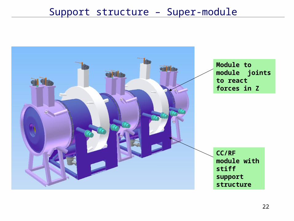
Support structure – Super-module
Module to module joints to react forces in Z
CC/RF module with stiff support structure

23
Support structure – Rail and Force transfer concept
Y
XZ
Magnetic force
Traverse in X on rail system to give location to +/- 2mmJack from rail and position in x-y-z to survey targets on vacuum vesselShim to blocking plates to locate in x-y-z and react forces
Module
Jacks
Rollers
Rails
Floor Plate
Y support location
Shim
Beam Axis
Survey Target

24
Support structure – Rail-mounting concept

25
Support structure – Force transfer concept - Y

26
Support structure – Force transfer concept - Z
27
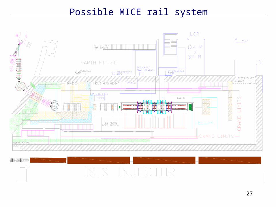
Possible MICE rail system

28
• Requirements/specification: - to move (all) MICE modules out the beam (to the side direction) for various MICE stages• Accuracy/tolerances: - along the beam +/- 1 mm - across the beam +/- 1 mm• Adjustment: - adjustment possibility is required.• Locking mechanism: - required.• Loads: - max load is 6.65 tonnes.• Force transfer function: - gravity force to the floor; - module-to-module axial force to the floor ?
MICE support structure - Specification

29
Module Weight, kg
AFC module 1700
RF module 4636
Radiation shield 310
Tracker module 6650(including 1200 kg of magnetic shield)
MICE support structure - Module weights
30
MICE support structure – Next steps• Revise support structure requirements/specs for full MICE - include and analyze requirements of access to every module ( collect information from all technical supervisors)
• Suggest support structure for Stage 2 (is it different from the one for complete MICE ?)
• Discuss revised version of support structure at RAL meeting