1 of 30 Fits and Tolerances 1. 2 of 30 Lecture Objectives Understand principles of Tolerances...
36
1 of 30 Fits and Tolerances 1
-
Upload
grant-stanley -
Category
Documents
-
view
243 -
download
13
Transcript of 1 of 30 Fits and Tolerances 1. 2 of 30 Lecture Objectives Understand principles of Tolerances...
1 of 30
Fits and Tolerances
1
2 of 30
Lecture Objectives
• Understand principles of Tolerances• Introduction to Fits• More than Two Parts Systems
2
3 of 30
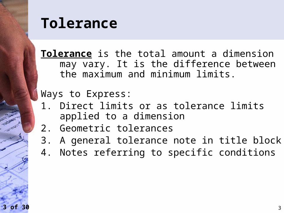
Tolerance
Tolerance is the total amount a dimension may vary. It is the difference between the maximum and minimum limits.
Ways to Express:1. Direct limits or as tolerance limits applied to a
dimension2. Geometric tolerances3. A general tolerance note in title block4. Notes referring to specific conditions
3
4 of 30
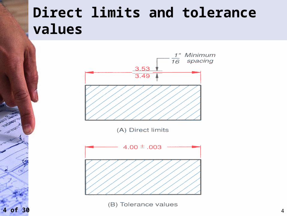
Direct limits and tolerance values
4
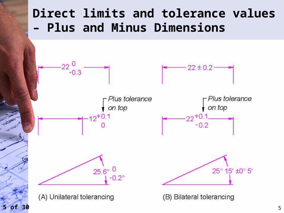
5 of 30
Direct limits and tolerance values – Plus and Minus Dimensions
5
6 of 30
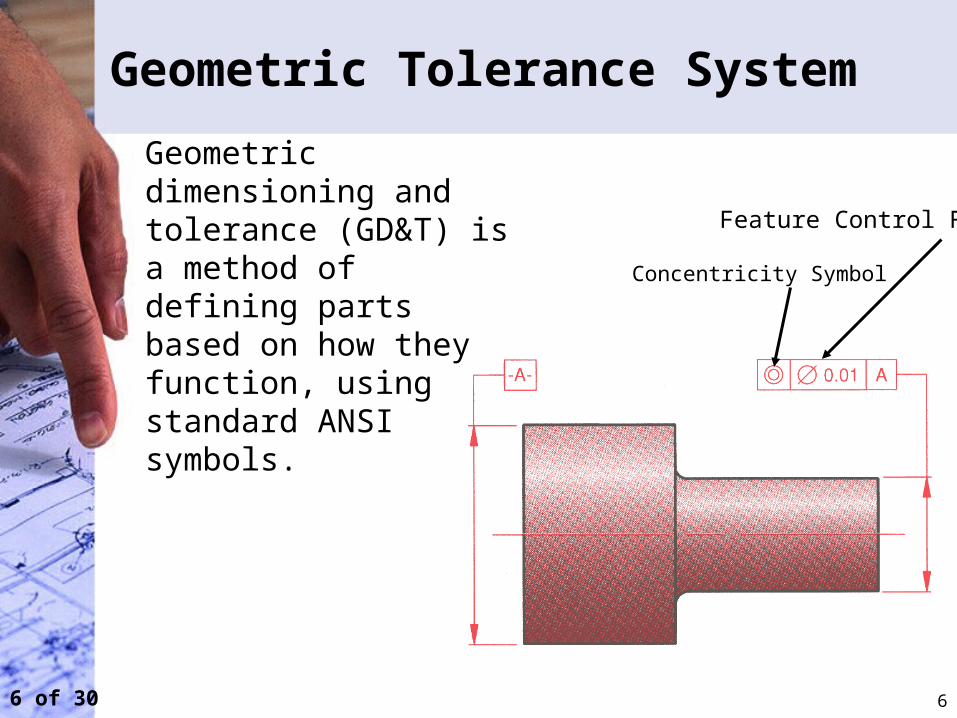
Geometric Tolerance System
6
Geometric dimensioning and tolerance (GD&T) is a method of defining parts based on how they function, using standard ANSI symbols.
Feature Control Frame
Concentricity Symbol
7 of 30
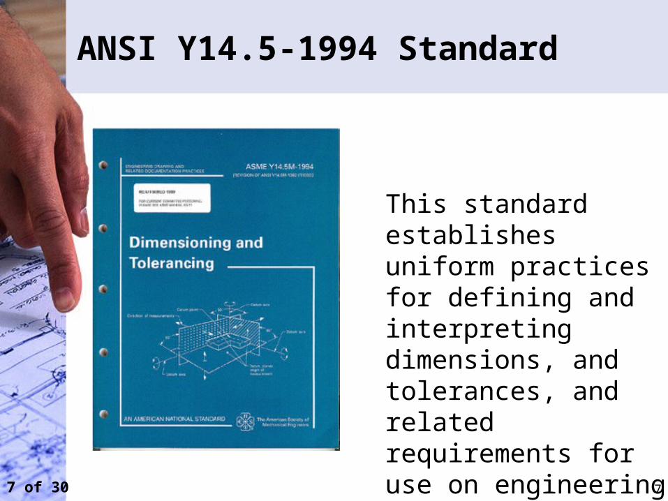
ANSI Y14.5-1994 Standard
This standard establishes uniform practices for defining and interpreting dimensions, and tolerances, and related requirements for use on engineering drawings.
7
8 of 30
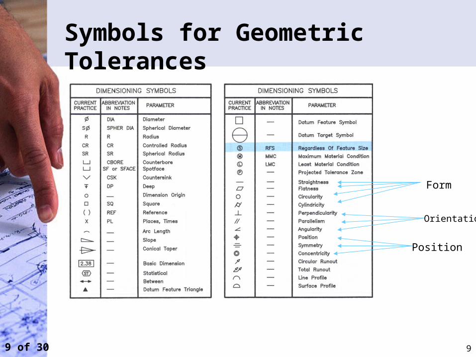
Overview of Geometric Tolerances
Geometric tolerances define the shape of a feature as opposed to its size.
Three basic types of dimensional tolerances:
1. Form tolerances: straightness, circularity, flatness, cylindercity;2. Orientation tolerances; perpendicularity, parallelism, angularity; 3. Position tolerances: position, symmetry, concentricity.
8
9 of 30
Symbols for Geometric Tolerances
Form
Orientation
Position
9
10 of 30
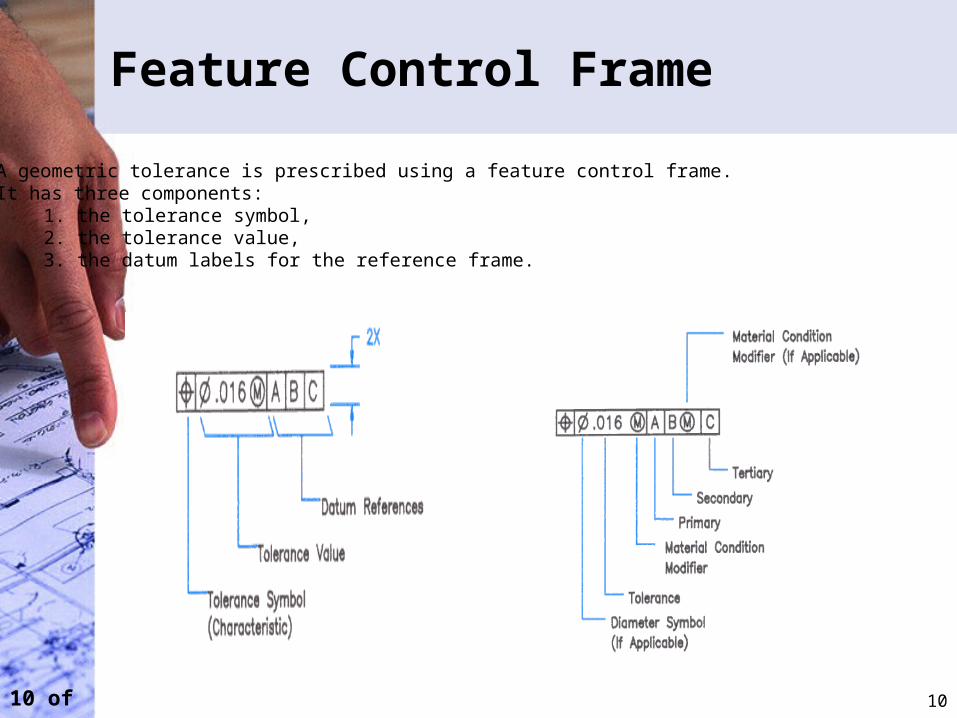
Feature Control Frame
A geometric tolerance is prescribed using a feature control frame.It has three components:
1. the tolerance symbol,2. the tolerance value,3. the datum labels for the reference frame.
10
11 of 30
Tolerance Specifications in Title Block
11
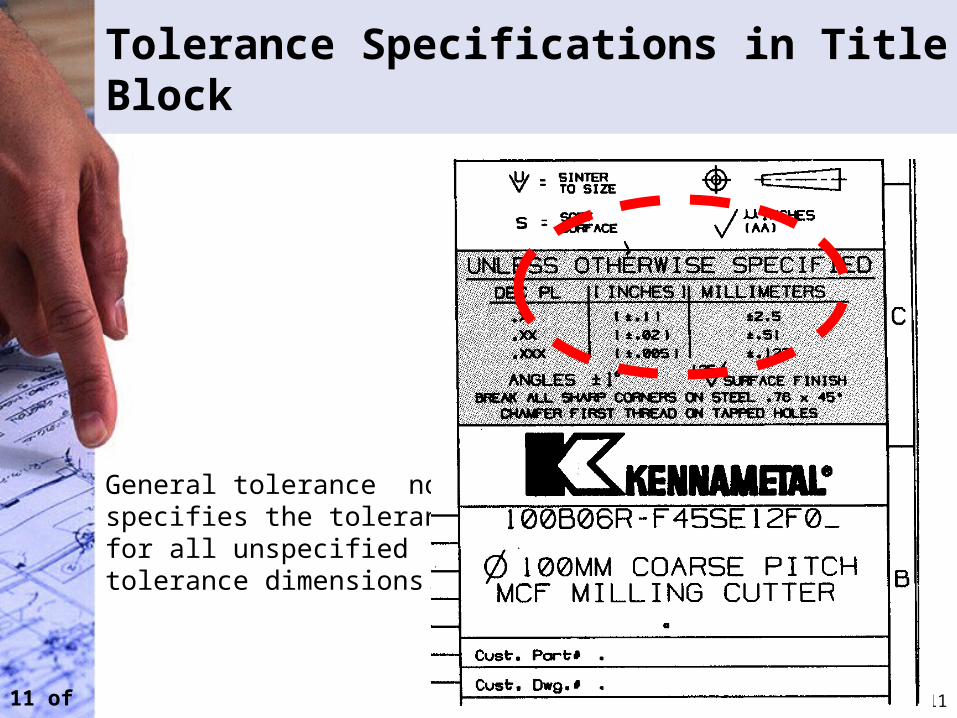
General tolerance note specifies the tolerance for all unspecified tolerance dimensions.
12 of 30
Notes referring to specific conditions
12
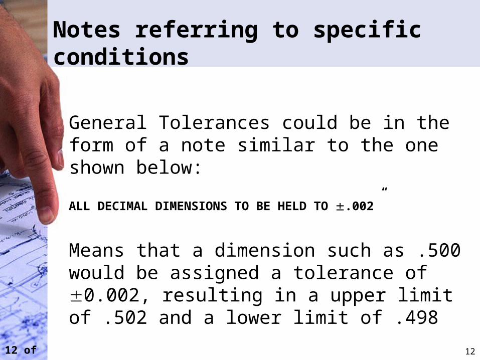
General Tolerances could be in the form of a note similar to the one shown below:
ALL DECIMAL DIMENSIONS TO BE HELD TO .002”
Means that a dimension such as .500 would be assigned a tolerance of 0.002, resulting in a upper limit of .502 and a lower limit of .498
13 of 30
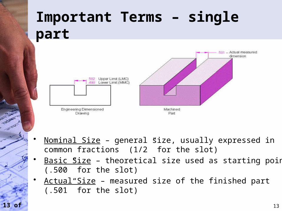
Important Terms – single part
• Nominal Size – general size, usually expressed in common fractions (1/2” for the slot)
• Basic Size – theoretical size used as starting point (.500” for the slot)• Actual Size – measured size of the finished part (.501” for the slot)
13
14 of 30
Important Terms – single part
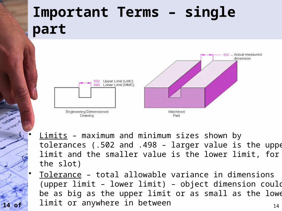
• Limits – maximum and minimum sizes shown by tolerances (.502 and .498 – larger value is the upper limit and the smaller value is the lower limit, for the slot)
• Tolerance – total allowable variance in dimensions (upper limit – lower limit) – object dimension could be as big as the upper limit or as small as the lower limit or anywhere in between
14
15 of 30
Important Terms – Multiple Parts
• Allowance – the minimum clearance or maximum interference between parts
• Fit – degree of tightness between two parts– Clearance Fit – tolerance of mating parts always
leave a space– Interference Fit – tolerance of mating parts always
interfere– Transition Fit – sometimes interfere, sometimes
clear
15
16 of 30
Material Conditions
• Maximum Material Condition (MMC): The condition in which a feature contains the maximum amount of material within the stated limits. e.g. minimum hole diameter, maximum shaft diameter.
• Least Material Condition (LMC): The condition in which a feature contains the least amount of material within the stated limits. e.g. maximum hole diameter, minimum shaft diameter
• Regardless of Feature Size (RFS): This is the default condition for all geometric tolerances. No bonus tolerances are allowed and functional gauges may not be used.
16
17 of 30
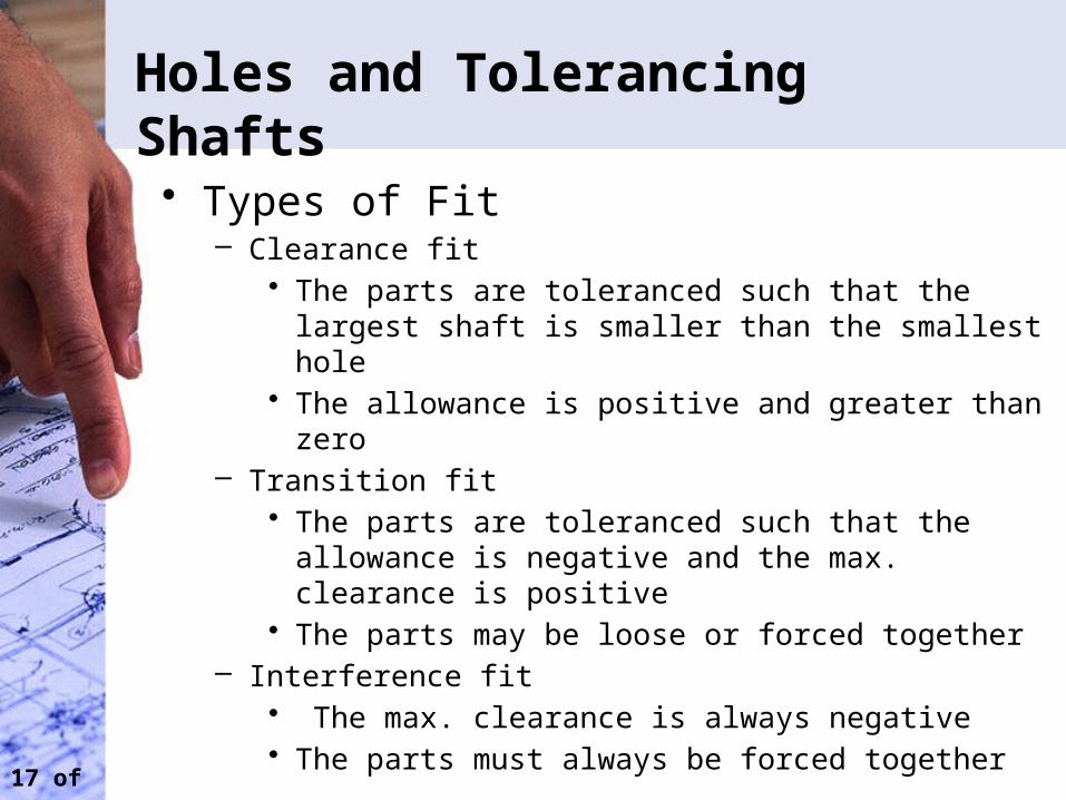
Holes and Tolerancing Shafts
• Types of Fit– Clearance fit
• The parts are toleranced such that the largest shaft is smaller than the smallest hole
• The allowance is positive and greater than zero– Transition fit
• The parts are toleranced such that the allowance is negative and the max. clearance is positive
• The parts may be loose or forced together– Interference fit
• The max. clearance is always negative• The parts must always be forced together
18 of 30
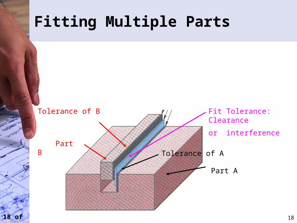
Fitting Multiple Parts
18
Part A
Tolerance of A Part B
Tolerance of B Fit Tolerance: Clearance
or interference
19 of 30
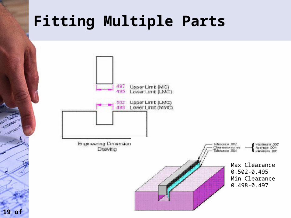
Fitting Multiple Parts
Max Clearance0.502-0.495Min Clearance0.498-0.497
20 of 30
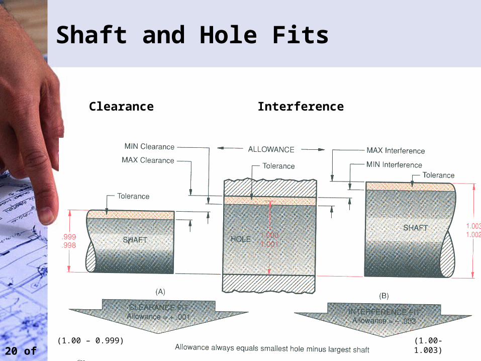
Shaft and Hole Fits
20
Clearance Interference
(1.00 – 0.999) (1.00- 1.003)
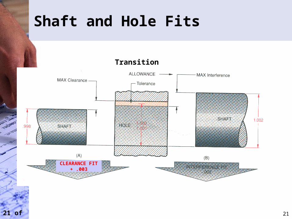
21 of 30
Shaft and Hole Fits
21
Transition
CLEARANCE FIT+ .003
22 of 30
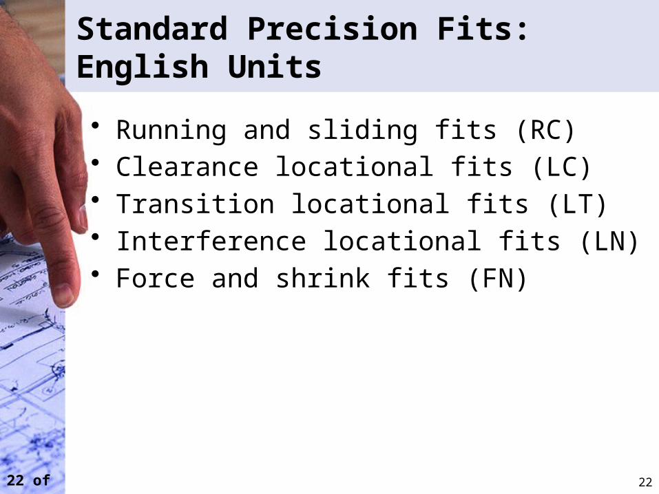
Standard Precision Fits: English Units
• Running and sliding fits (RC)• Clearance locational fits (LC)• Transition locational fits (LT)• Interference locational fits (LN)• Force and shrink fits (FN)
22
23 of 30
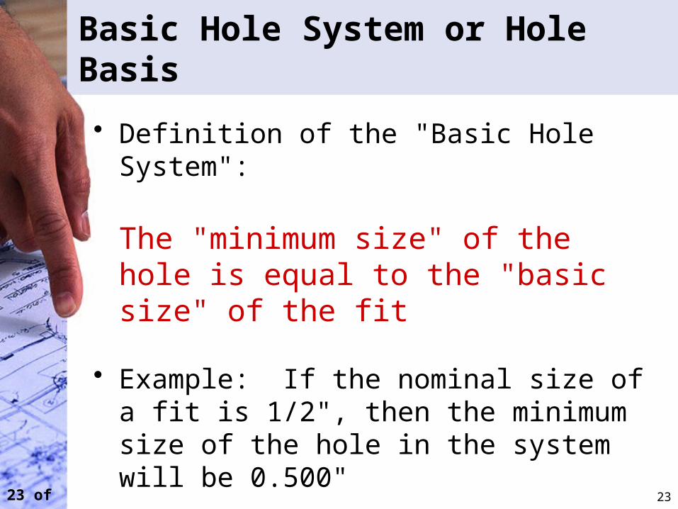
Basic Hole System or Hole Basis
• Definition of the "Basic Hole System":
The "minimum size" of the hole is equal to the "basic size" of the fit
• Example: If the nominal size of a fit is 1/2", then the minimum size of the hole in the system will be 0.500"
23
24 of 30
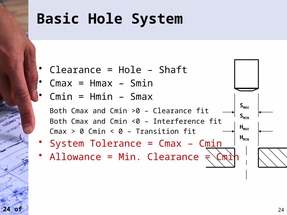
Basic Hole System
• Clearance = Hole – Shaft• Cmax = Hmax – Smin• Cmin = Hmin – Smax
Both Cmax and Cmin >0 – Clearance fit
Both Cmax and Cmin <0 – Interference fit
Cmax > 0 Cmin < 0 – Transition fit
• System Tolerance = Cmax – Cmin• Allowance = Min. Clearance = Cmin
24
SMAX
SMIN
HMAX
HMIN
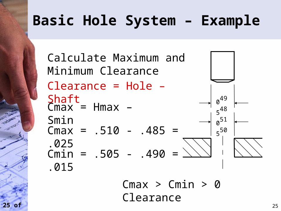
25 of 30
Basic Hole System – Example
25
.490
.485
.510
.505
Calculate Maximum and Minimum ClearanceClearance = Hole – Shaft
Cmax = Hmax – Smin
Cmax = .510 - .485 = .025
Cmin = .505 - .490 = .015
Cmax > Cmin > 0 Clearance
26 of 30
Metric Limits and Fits
• Note that in the Metric system:
Nominal Size = Basic Size• Example: If the nominal size is 8, then the
basic size is 8
26
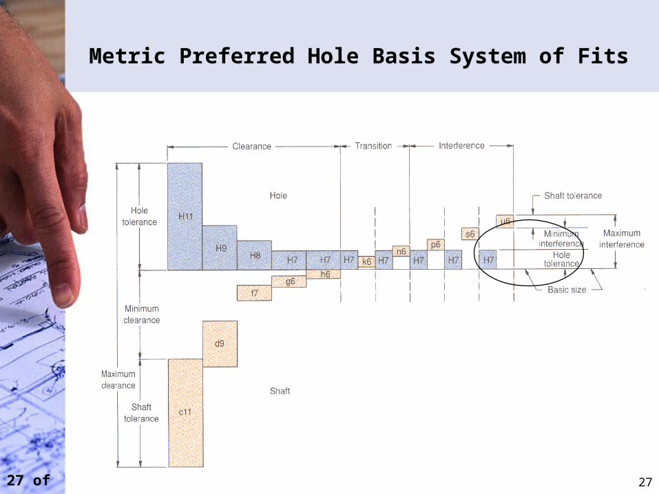
27 of 30
Metric Preferred Hole Basis System of Fits
27
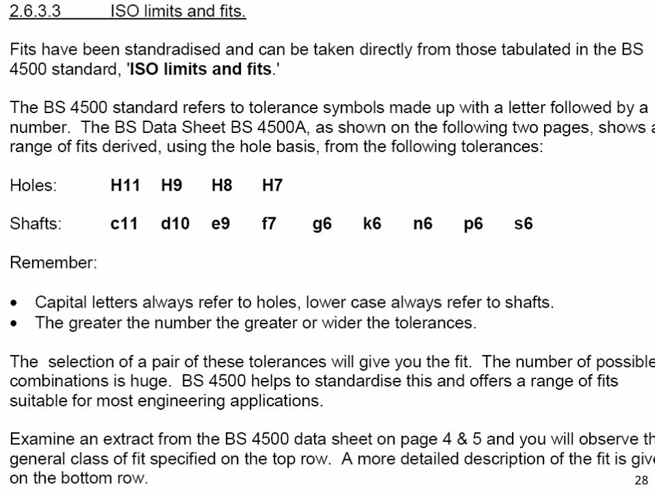
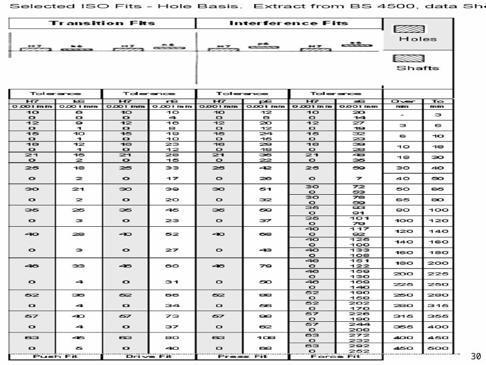
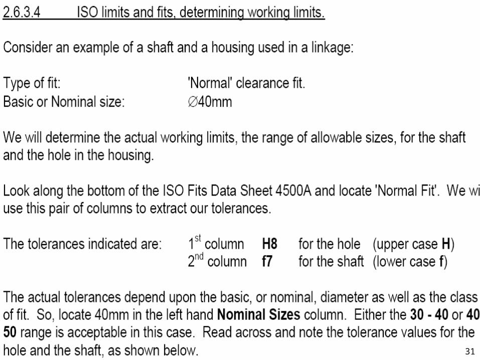
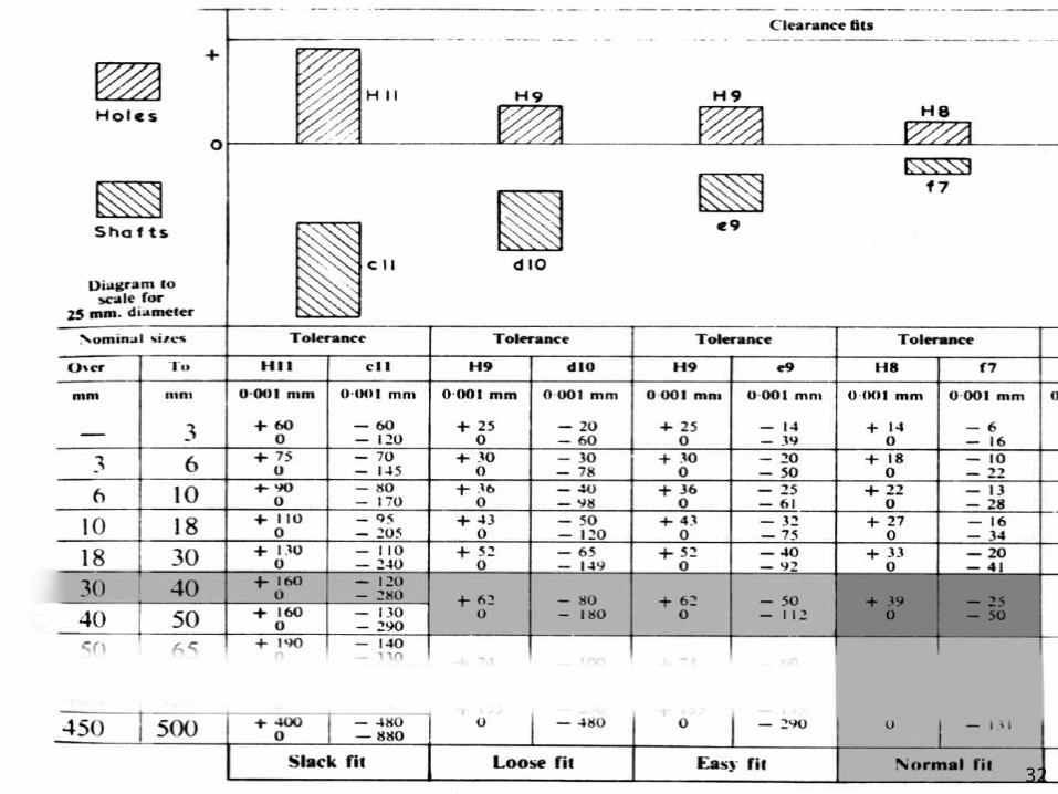
28 of 30 28
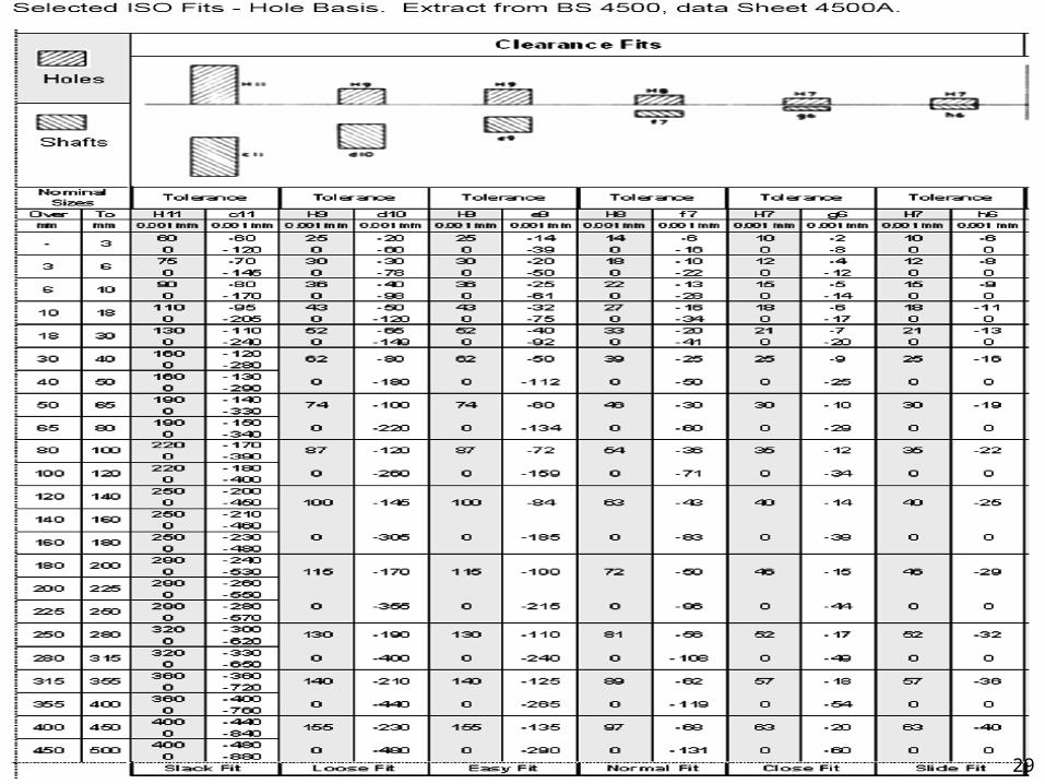
29 of 30 29
30 of 30 30
31 of 30 31
32 of 30 32
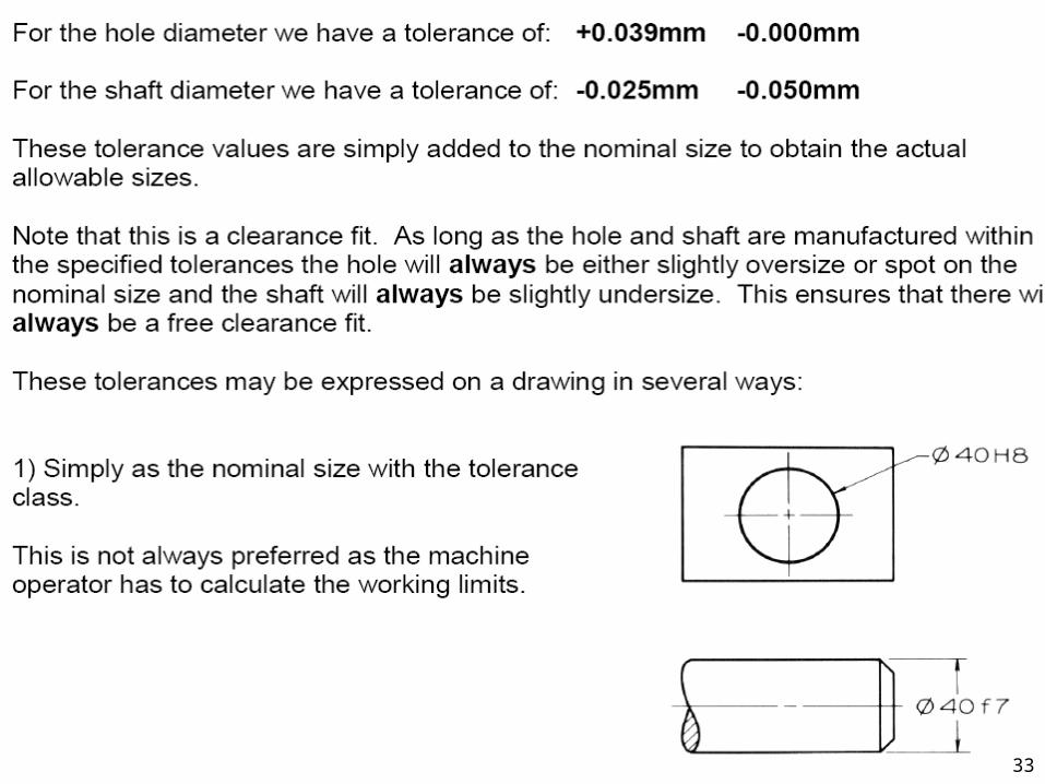
33 of 30 33
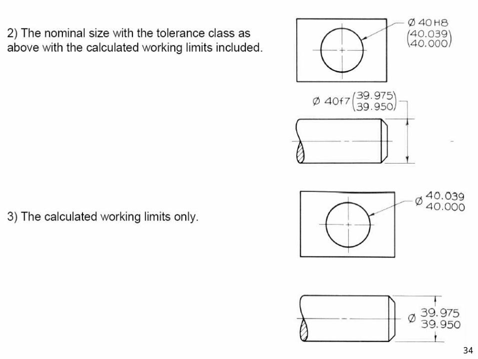
34 of 30 34
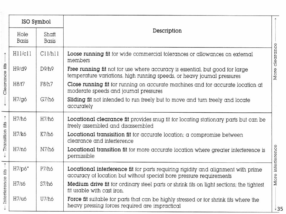
35 of 30 35
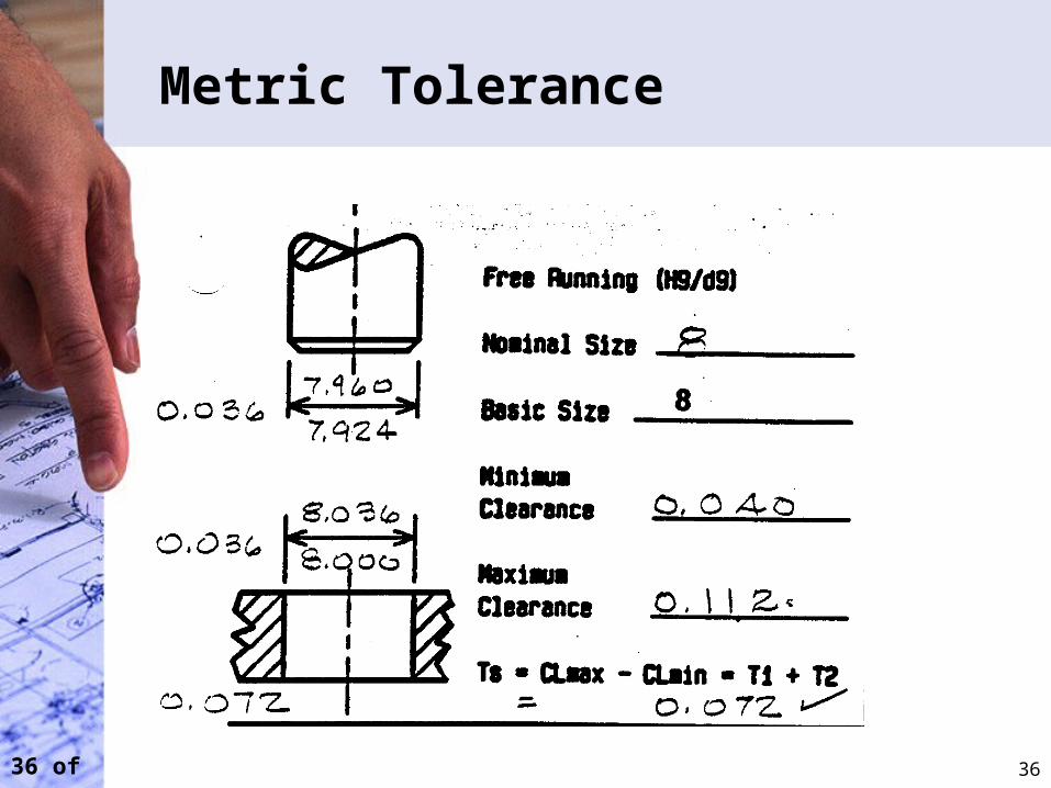
36 of 30
Metric Tolerance
36