Chapter 3 limits, fits and tolerances
16
05-09-2014 1 LIMITS, FITS AND TOLERANCES Dr. Dayananda Pai Aero & Auto Engg. Dept., M.I.T. Manipal Objectives • After studying the material in this module, student should be able to : • Read and create limit dimensions. • Describe the nominal size, tolerance, limits and allowance of two mating parts. • Identify a clearance fit, interference fit and transition fit. • Describe the basic hole and basic shaft system. • Dimension two mating parts using limit dimensions, unilateral tolerances, and bilateral tolerances. • Describe the classes of fit and give example of each. Why study Limits & Fits? • In manufacturing it is impossible to produce components to an exact size, even though they may be classified as identical. • However, industry does demand that parts should be produced between a given basic size. • The difference between these sizes is called the “tolerance” which can be defined as “the amount of variation in size which is tolerated”. A broad, generous tolerance is cheaper to produce and maintain than a narrow precise one.
-
Upload
vishalm580 -
Category
Engineering
-
view
477 -
download
31
Transcript of Chapter 3 limits, fits and tolerances
05-09-2014
1
LIMITS, FITS AND
TOLERANCES Dr. Dayananda Pai
Aero & Auto Engg. Dept.,
M.I.T. Manipal
Objectives
• After studying the material in this module, student should
be able to :
• Read and create limit dimensions.
• Describe the nominal size, tolerance, limits and allowance
of two mating parts.
• Identify a clearance fit, interference fit and transition fit.
• Describe the basic hole and basic shaft system.
• Dimension two mating parts using limit dimensions,
unilateral tolerances, and bilateral tolerances.
• Describe the classes of fit and give example of each.
Why study Limits & Fits?
• In manufacturing it is impossible to produce components
to an exact size, even though they may be classified as
identical.
• However, industry does demand that parts should be
produced between a given basic size.
• The difference between these sizes is called the
“tolerance” which can be defined as “the amount of
variation in size which is tolerated”. A broad, generous
tolerance is cheaper to produce and maintain than a
narrow precise one.
05-09-2014
2
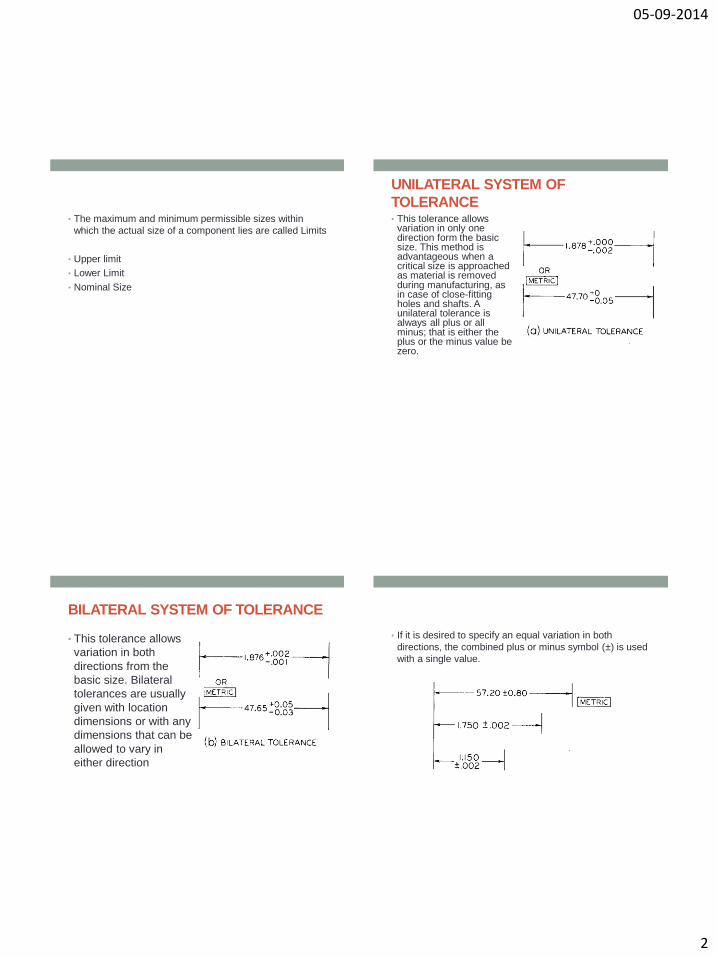
• The maximum and minimum permissible sizes within
which the actual size of a component lies are called Limits
• Upper limit
• Lower Limit
• Nominal Size
UNILATERAL SYSTEM OF
TOLERANCE • This tolerance allows
variation in only one direction form the basic size. This method is advantageous when a critical size is approached as material is removed during manufacturing, as in case of close-fitting holes and shafts. A unilateral tolerance is always all plus or all minus; that is either the plus or the minus value be zero.
BILATERAL SYSTEM OF TOLERANCE
• This tolerance allows
variation in both
directions from the
basic size. Bilateral
tolerances are usually
given with location
dimensions or with any
dimensions that can be
allowed to vary in
either direction
• If it is desired to specify an equal variation in both
directions, the combined plus or minus symbol (±) is used
with a single value.
05-09-2014
3
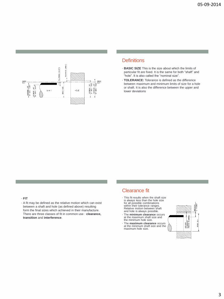
Definitions
• BASIC SIZE This is the size about which the limits of
particular fit are fixed. It is the same for both “shaft” and
“hole”. It is also called the “nominal size”.
• TOLERANCE: Tolerance is defined as the difference
between maximum and minimum limits of size for a hole
or shaft. It is also the difference between the upper and
lower deviations
• FIT
• A fit may be defined as the relative motion which can exist
between a shaft and hole (as defined above) resulting
form the final sizes which achieved in their manufacture.
There are three classes of fit in common use : clearance,
transition and interference.
Clearance fit
• This fit results when the shaft size is always less than the hole size for all possible combinations within their tolerance ranges. Relative motion between shaft and hole is always possible.
• The minimum clearance occurs at the maximum shaft size and the minimum hole size.
• The maximum clearance occurs at the minimum shaft size and the maximum hole size.
05-09-2014
4
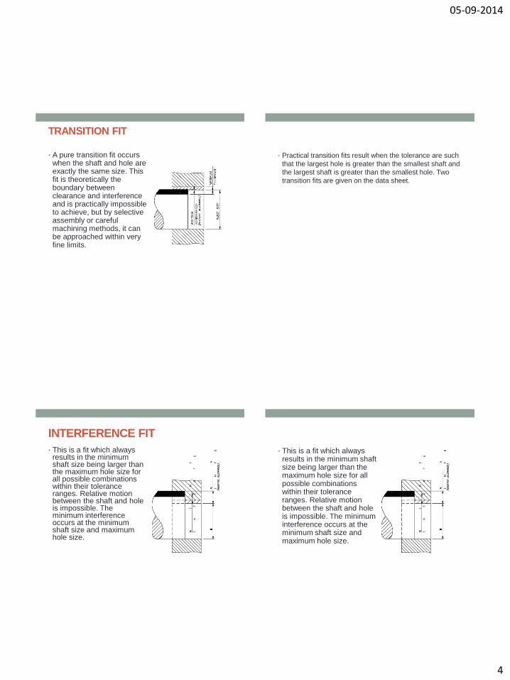
TRANSITION FIT
• A pure transition fit occurs when the shaft and hole are exactly the same size. This fit is theoretically the boundary between clearance and interference and is practically impossible to achieve, but by selective assembly or careful machining methods, it can be approached within very fine limits.
• Practical transition fits result when the tolerance are such
that the largest hole is greater than the smallest shaft and
the largest shaft is greater than the smallest hole. Two
transition fits are given on the data sheet.
INTERFERENCE FIT
• This is a fit which always results in the minimum shaft size being larger than the maximum hole size for all possible combinations within their tolerance ranges. Relative motion between the shaft and hole is impossible. The minimum interference occurs at the minimum shaft size and maximum hole size.
• This is a fit which always results in the minimum shaft size being larger than the maximum hole size for all possible combinations within their tolerance ranges. Relative motion between the shaft and hole is impossible. The minimum interference occurs at the minimum shaft size and maximum hole size.
05-09-2014
5
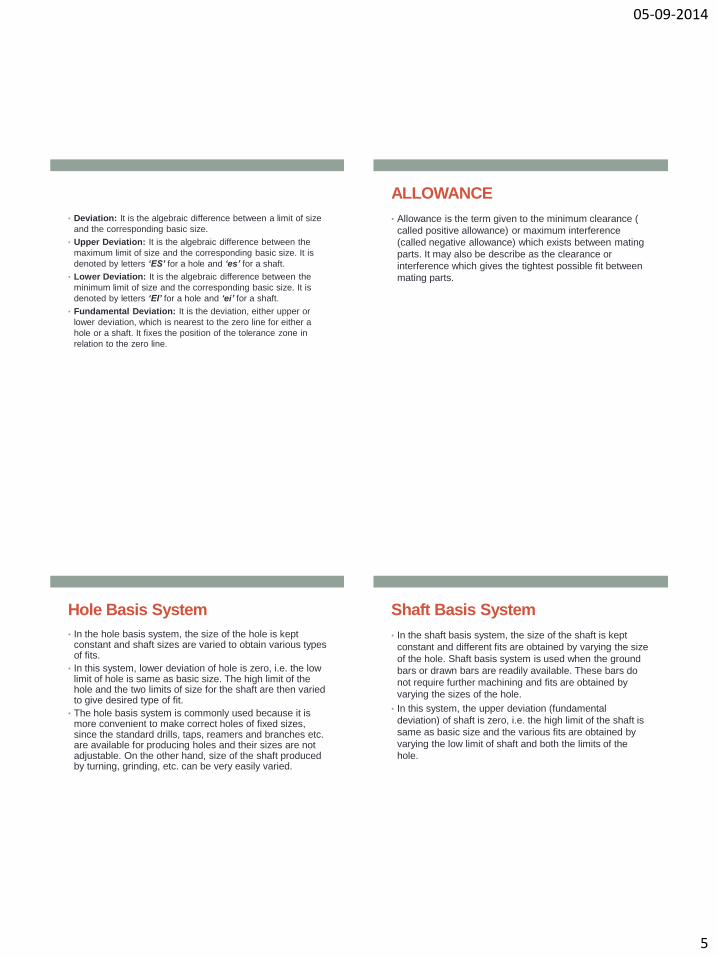
• Deviation: It is the algebraic difference between a limit of size
and the corresponding basic size.
• Upper Deviation: It is the algebraic difference between the
maximum limit of size and the corresponding basic size. It is
denoted by letters ‘ES’ for a hole and ‘es’ for a shaft.
• Lower Deviation: It is the algebraic difference between the
minimum limit of size and the corresponding basic size. It is
denoted by letters ‘EI’ for a hole and ‘ei’ for a shaft.
• Fundamental Deviation: It is the deviation, either upper or
lower deviation, which is nearest to the zero line for either a
hole or a shaft. It fixes the position of the tolerance zone in
relation to the zero line.
ALLOWANCE
• Allowance is the term given to the minimum clearance (
called positive allowance) or maximum interference
(called negative allowance) which exists between mating
parts. It may also be describe as the clearance or
interference which gives the tightest possible fit between
mating parts.
Hole Basis System
• In the hole basis system, the size of the hole is kept constant and shaft sizes are varied to obtain various types of fits.
• In this system, lower deviation of hole is zero, i.e. the low limit of hole is same as basic size. The high limit of the hole and the two limits of size for the shaft are then varied to give desired type of fit.
• The hole basis system is commonly used because it is more convenient to make correct holes of fixed sizes, since the standard drills, taps, reamers and branches etc. are available for producing holes and their sizes are not adjustable. On the other hand, size of the shaft produced by turning, grinding, etc. can be very easily varied.
Shaft Basis System
• In the shaft basis system, the size of the shaft is kept
constant and different fits are obtained by varying the size
of the hole. Shaft basis system is used when the ground
bars or drawn bars are readily available. These bars do
not require further machining and fits are obtained by
varying the sizes of the hole.
• In this system, the upper deviation (fundamental
deviation) of shaft is zero, i.e. the high limit of the shaft is
same as basic size and the various fits are obtained by
varying the low limit of shaft and both the limits of the
hole.
05-09-2014
6
• Interchangeability:
Interchangeability occurs when one part in an assembly
can be substituted for a similar part which has been made
to the same drawing. Interchangeability is possible only
when certain standards are strictly followed.
• Universal interchangeability means the parts to be
assembled are from two different manufacturing sources.
• Local interchangeability means all the parts to be
assembled are made in the same manufacturing unit.
• Selective Assembly:
• In selective assembly, the parts are graded according to the size and only matched grades of mating parts are assembled. This technique is most suitable where close fit of two components assembled is required.
• Suppose some parts (shafts & holes) are manufactured to a tolerance of 0.01 mm, then an automatic gauge can separate them into ten different groups of 0.001 mm limit for selective assembly of the individual parts. Thus high quality and low cost can be achieved.
• Selective assembly is used in aircraft, automobile industries where tolerances are very narrow and not possible to manufacture at reasonable costs.
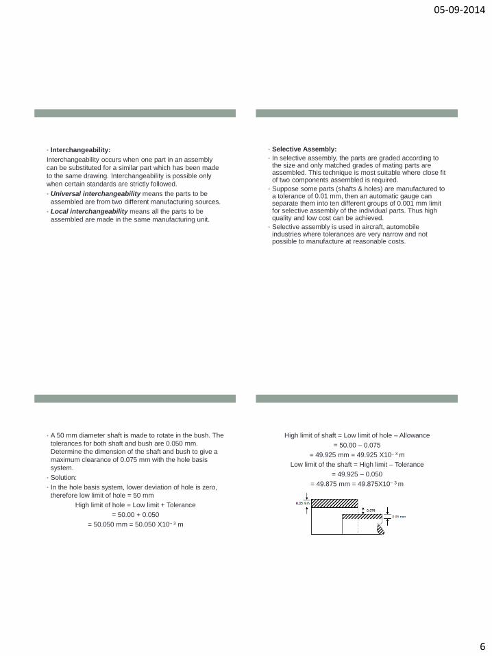
• A 50 mm diameter shaft is made to rotate in the bush. The
tolerances for both shaft and bush are 0.050 mm.
Determine the dimension of the shaft and bush to give a
maximum clearance of 0.075 mm with the hole basis
system.
• Solution:
• In the hole basis system, lower deviation of hole is zero,
therefore low limit of hole = 50 mm
High limit of hole = Low limit + Tolerance
= 50.00 + 0.050
= 50.050 mm = 50.050 X10– 3 m
High limit of shaft = Low limit of hole – Allowance
= 50.00 – 0.075
= 49.925 mm = 49.925 X10– 3 m
Low limit of the shaft = High limit – Tolerance
= 49.925 – 0.050
= 49.875 mm = 49.875X10– 3 m
05-09-2014
7
• For each of the following hole and shaft assembly, find
shaft-tolerance, hole tolerance and state whether the type
of fit is (a) clearance, (b) transition, and (c) interference.
• Hole Shaft
• Hole Shaft
• Hole Shaft
mm025.000.050 mm05.0
005.050
mm05.000.050
mm02.0
05.050
mm04.000.050
mm06.0
04.050
Hole : High limit of hole = 50.025 mm
Low limit of hole = 50.00 mm
Hole tolerance = 50.025 – 50.00 = 0.025 mm
Shaft : High limit of shaft = 50.05 mm
Low limit of shaft = 50.005 mm
Shaft tolerance = 50.05 – 50.005 = 0.045 mm
If we choose high limit of hole with high limit of shaft then
Allowance = 50.025 – 50.05
= – 0.025 (Interference)
But high limit of hole is smaller than low limit of shaft (clearance)
Thus, we conclude that the type of fit is Transition fit.
• Hole : High limit = 50.05 mm
• Low limit = 50.00 mm
• Tolerance = 0.05 mm
• Shaft : High limit = 50 – 0.02 = 49.98 mm
• Low limit = 50 – 0.05 = 49.95 mm
• Tolerance = 49.98 – 49.95 = 0.0 3 mm
• If we select high limit of hole and high limit of shaft then
• Allowance = 50.05 – 49.98 = 0.07 mm
• If we choose low limit of hole and high limit of shaft then
• Allowance = 50.00 – 49.98 = 0.02 mm
• Thus, we conclude that the type of fit is Clearance fit.
• High limit = 50.04 mm
• Low limit = 50.00 mm
• Tolerance = 50.04 – 50.00
• = 0.04 mm
• Shaft : High limit = 50.06 mm
• Low limit = 50.04 mm
• Tolerance = 50.06 – 50.04
• = 0.02 mm
• If we select high limit of shaft and low limit of hole, then
• Allowance = 50.00 – 50.06
• = – 0.06 mm
• It is clear that for any combination of hole and shaft the allowance will be negative.
• Thus, we conclude that the type of fit is Interference fit.
05-09-2014
8
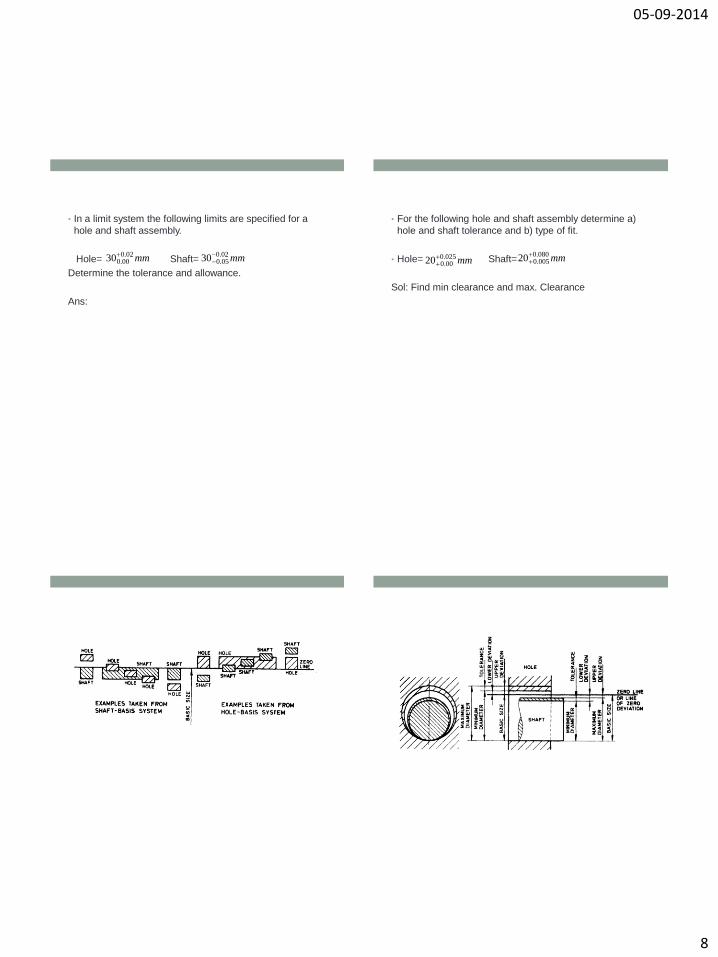
• In a limit system the following limits are specified for a
hole and shaft assembly.
Hole= Shaft=
Determine the tolerance and allowance.
Ans:
mm02.000.030 mm02.0
05.030
• For the following hole and shaft assembly determine a)
hole and shaft tolerance and b) type of fit.
• Hole= Shaft=
Sol: Find min clearance and max. Clearance
mm025.000.020
mm080.0
005.020
05-09-2014
9
SYSTEM OF LIMITS AND FITS
• Rapid growth of national & International Business
• Economic success of Manufacturing industries.
• International Organisation for Standardisation (ISO) specifies the internationally accepted system of limits and fits.
• IS system of limits and fits comprises 18 grades of fundamental tolerances to indicate the level of accuracy.
• They are designated by ‘IT’ followed by a Number.
• 18 grades are IT01, IT0, and IT1 to IT16. (ISO system comprise 20 grades)
• Fine grades are referred to by the first few numbers. As the numbers get larger, so the tolerance zone becomes progressively wider
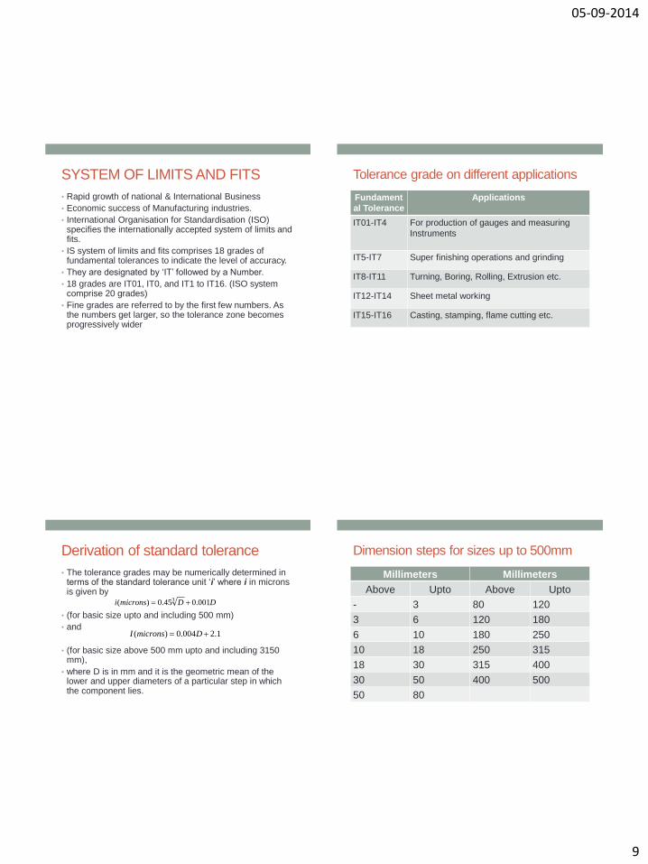
Tolerance grade on different applications
Fundament
al Tolerance
Applications
IT01-IT4 For production of gauges and measuring
Instruments
IT5-IT7 Super finishing operations and grinding
IT8-IT11 Turning, Boring, Rolling, Extrusion etc.
IT12-IT14 Sheet metal working
IT15-IT16 Casting, stamping, flame cutting etc.
Derivation of standard tolerance
• The tolerance grades may be numerically determined in terms of the standard tolerance unit ‘i’ where i in microns is given by
• (for basic size upto and including 500 mm)
• and
• (for basic size above 500 mm upto and including 3150 mm),
• where D is in mm and it is the geometric mean of the lower and upper diameters of a particular step in which the component lies.
DDmicronsi 001.045.0)( 3
1.2004.0)( DmicronsI
Dimension steps for sizes up to 500mm
Millimeters Millimeters
Above Upto Above Upto
- 3 80 120
3 6 120 180
6 10 180 250
10 18 250 315
18 30 315 400
30 50 400 500
50 80
05-09-2014
10
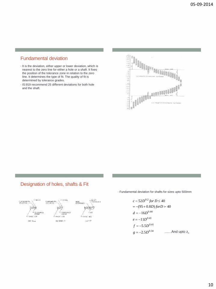
Fundamental deviation
• It is the deviation, either upper or lower deviation, which is
nearest to the zero line for either a hole or a shaft. It fixes
the position of the tolerance zone in relation to the zero
line. It determines the type of fit. The quality of fit is
determined by tolerance grades.
• IS:919 recommend 25 different deviations for both hole
and the shaft.
Designation of holes, shafts & Fit
• Fundamental deviation for shafts for sizes upto 500mm
34.0
41.0
41.0
44.0
2.0
5.2
5.5
11
16
40)8.095(
4052
Dg
Df
De
Dd
DforD
DforDc
……And upto zc
05-09-2014
11
Dowel Pins
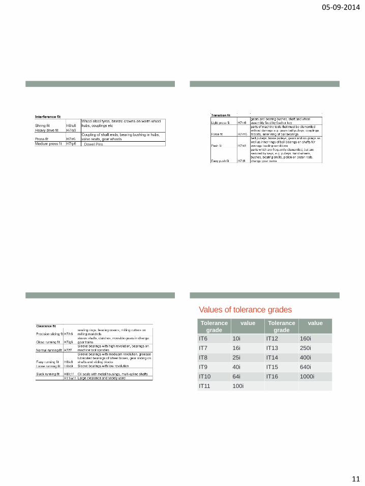
Values of tolerance grades
Tolerance
grade
value Tolerance
grade
value
IT6 10i IT12 160i
IT7 16i IT13 250i
IT8 25i IT14 400i
IT9 40i IT15 640i
IT10 64i IT16 1000i
IT11 100i
05-09-2014
12
Tolerance grades IT01 to IT05
• IT01=0.3+0.008D
• IT0=0.5+0.012D
• IT1=0.8+0.020D
• IT5=0.7*IT6=0.7*10i=7i and so on.
Calculation of tolerance and limit of size
• 60H8f7
• Step 1: (Calculation of basic size)
Given size falls in the diameter steps 50-80mm Hence
D=
• Step 2: (fundamental deviation for hole)
For H hole FD=0
• Step 3:(Fundamental deviation for shaft)
For f shaft es= -5.5D0.41
= -30.113 microns~ -30 microns= -0.030mm
mm25.638050
• Step 4: (Tolerance unit)
• Step 5: Tolerance grade IT8 for hole =25i=46.4
microns=0.046mm
• Similarly Tolerance grade for IT7=0.030mm
• Step 5: Calculation of limits
• (i) Hole: Low limit
Basic size +FD for hole=60+0.000=60.000 mm
High Limit
Low limit + Tolerance=60.046mm
micronsDDmicronsi 856.1001.045.0)( 3
• (ii) Shaft: High limit =Basic size - FD for Shaft=
60.00-0.030=59.970mm
Low Limit=High limit – tolerance =
59.970 – 0.030 = 59.940mm
05-09-2014
13
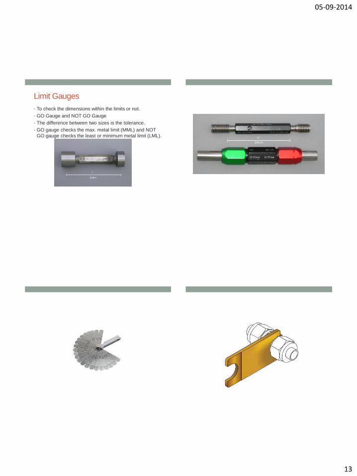
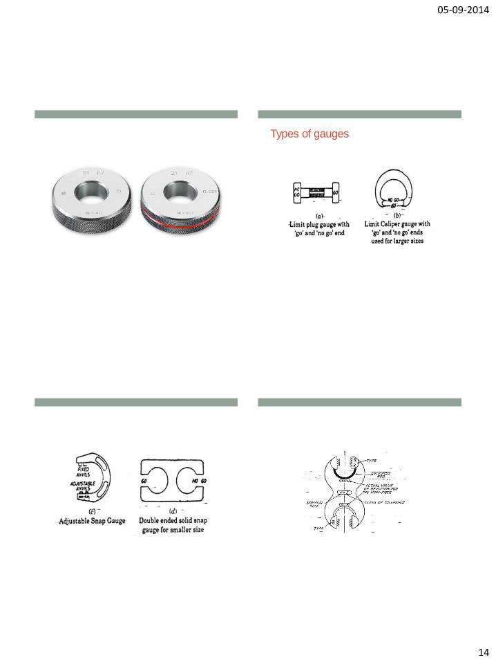
Limit Gauges
• To check the dimensions within the limits or not.
• GO Gauge and NOT GO Gauge
• The difference between two sizes is the tolerance.
• GO gauge checks the max. metal limit (MML) and NOT
GO gauge checks the least or minimum metal limit (LML).
05-09-2014
14
Types of gauges
05-09-2014
15
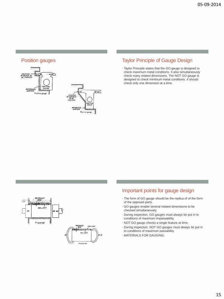
Position gauges
Taylor Principle of Gauge Design
• Taylor Principle states that the GO gauge is designed to
check maximum metal conditions. It also simultaneously
check many related dimensions. The NOT GO gauge is
designed to check minimum metal conditions. It should
check only one dimension at a time.
Important points for gauge design
• The form of GO gauge should be the replica of of the form
of the opposed parts.
• GO gauges enable several related dimensions to be
checked simultaneously.
• During inspection, GO gauges must always be put in to
conditions of maximum impassability.
• NOT GO gauge checks a single feature at time.
• During inspection, NOT GO gauges must always be put in
to conditions of maximum passability.
• MATERIALS FOR GAUGING:
05-09-2014
16
Gauge Tolerance
• There is no universally accepted policy for
deciding the amount of tolerance to be
provided on the gauges. (10% of the work
tolerance)
• Wear tolerance: GO gauge wears. But NOT
GO gauge does not.
• A wear allowance of 10% of gauge
tolerance is widely used.
Method of Tolerance specification on
Gauges (BS or IS system) This system works according to the following guidelines
• The specified tolerance should be wide and at the same
time consistent with satisfactory functioning economical
production and inspection.
• During inspection the work that lies outside the specified
limits should not be accepted.
Thus in this system the same tolerance limits are specified
on w/s and insp. gauges.
Example
• Design a general type of GO and NOT GO gauges as per
the BS system for a 40 mm shaft and hole pair designated
as 40H8/d9 given that
• Diameter range 30-50 mm.
• IT8=25i IT9=40i
• Upper deviation of shaft =-16D0.44
• Wear allowance= 10% of gauge tolerance.
DDmicronsi 001.045.0)( 3