MICE Alignment and Support Structure Tony Jones and Yury Ivanyushenkov Engineering Department RAL.
date post
22-Dec-2015Category
view
214download
0
1
MICE Hall Layout
MICE Collaboration Meeting, LBNL, February 12, 2005
Paul Drummfor
Yury & the RAL team
2
• Hall layout
• Beam line shielding layout
• PSI solenoid infrastructure layout
• Plans
Access to MICE & ISIS running
Scope
3
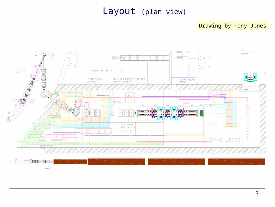
Layout (plan view)
Drawing by Tony Jones
4
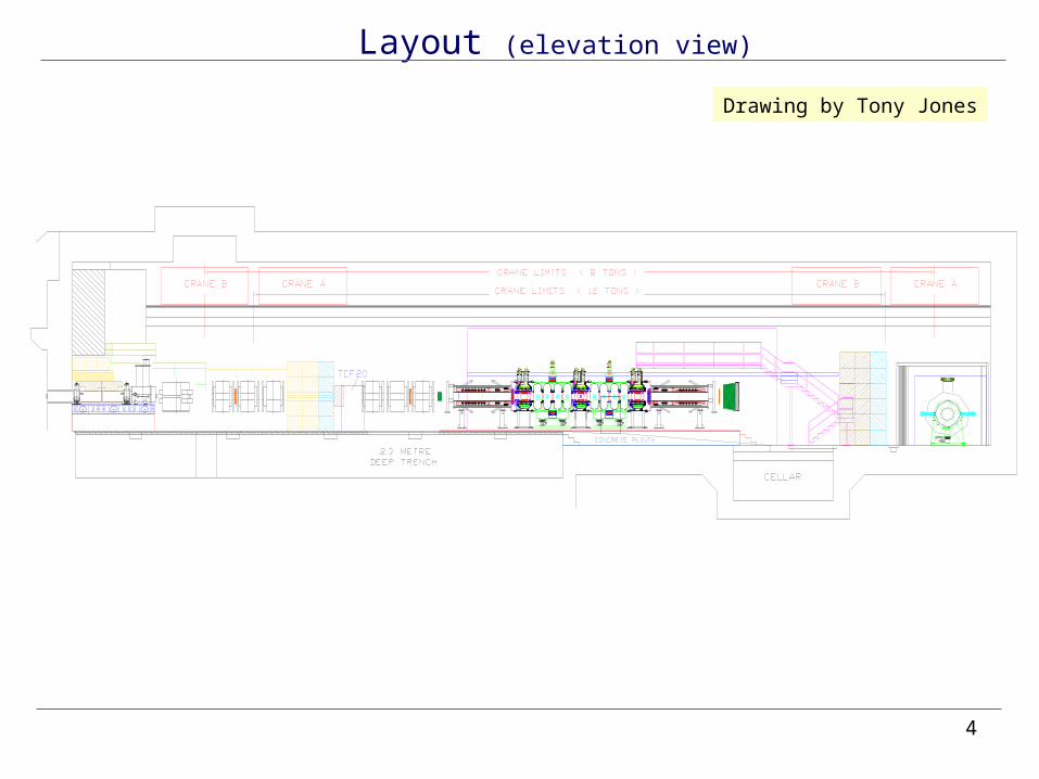
Layout (elevation view)
Drawing by Tony Jones
5
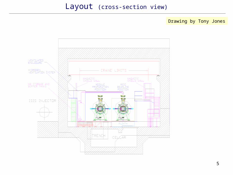
Layout (cross-section view)
Drawing by Tony Jones
6
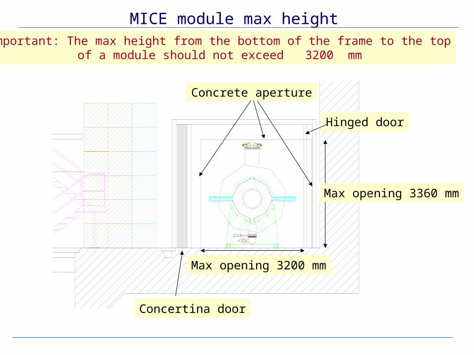
MICE module max height
Concrete aperture
Important: The max height from the bottom of the frame to the topof a module should not exceed 3200 mm
Concertina door
Hinged door
Max opening 3200 mm
Max opening 3360 mm
7
MICE and beam line shielding
Consultations with ISIS Radiation Safety Officer:
Implemented:
• Beam line radiation shielding:- Roofed block house; no- Labyrinth –type entrance; yes- 1.5 m of steel + 0.75 m of concrete in the direction of the beam; yes
- Temporarily shielding block (1.5 m of steel + 0.75 m of concrete) yes + 1 m of concrete (very recent demand)); not yet
- Beam stopper. Yes(!)
• MICE radiation shielding:- Shielded doors yes- Room for possible shielding for ISIS ion source hall; yes- Room for possible shielding for ISIS control room yes
8
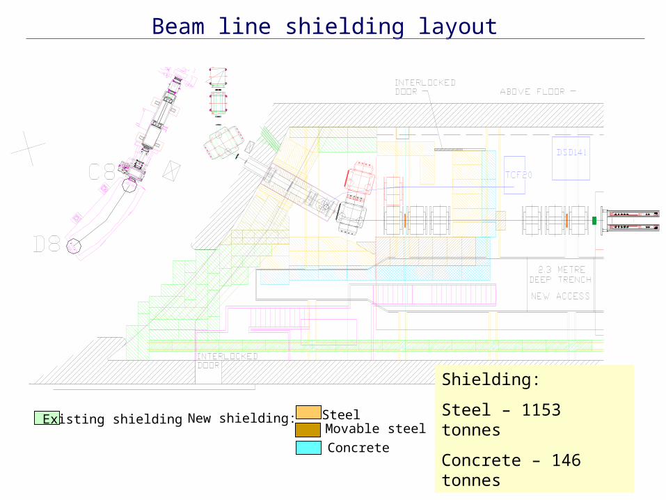
Beam line shielding layout
Shielding:
Steel – 1153 tonnes
Concrete – 146 tonnesExisting shielding New shielding: Steel
Movable steel
Concrete
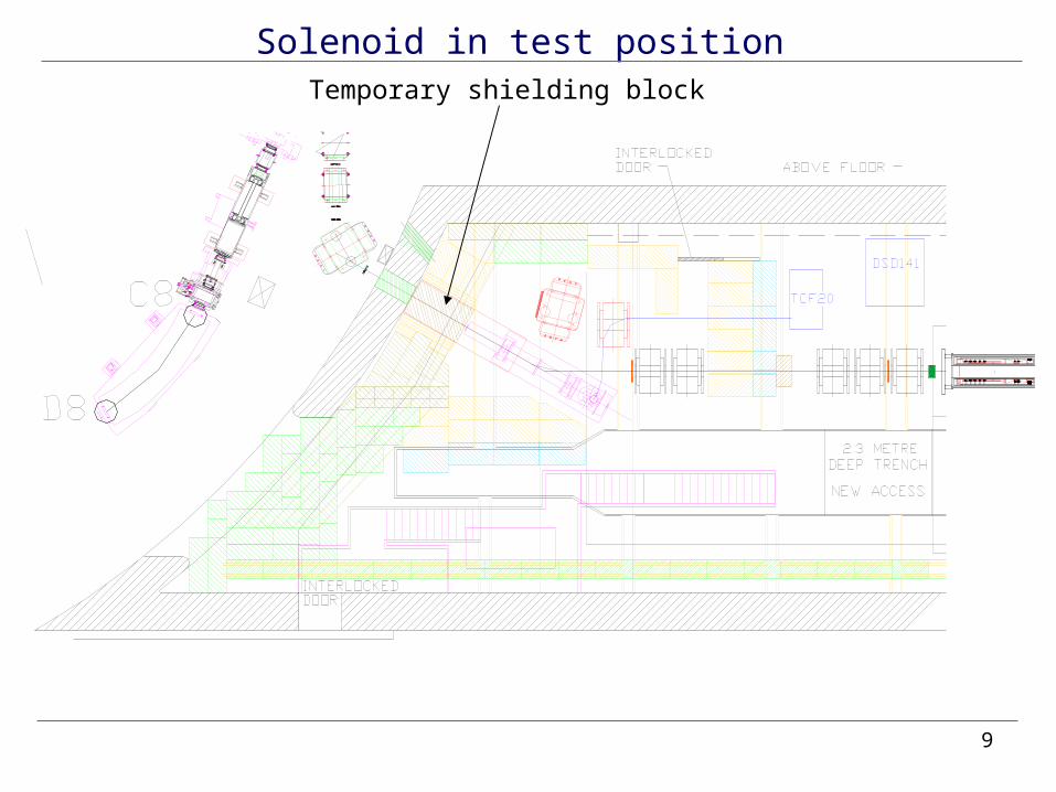
9
Solenoid in test positionTemporary shielding block
10
MICE and beam line shielding: Problems and solutions
Problem: • Very heavily shielded beam line high cost can MICE afford it ?
But do we really need that heavy shielding ?
Solution:• Calculate doses in the MICE hall for the worst scenario case• Optimize the shielding • Discuss the issue again with ISIS Safety Officer
11
PSI solenoid infrastructure
• Magnet preparation for shipment : - New nose piece and temporary lead shielding (design completed). - Need to agree few technical issues for transport with PSI.
• Cryogenics- layout (suggested)
- specs (ready)
• Site for compressor (suggested)
• Support structure (conceptual design completed)
12
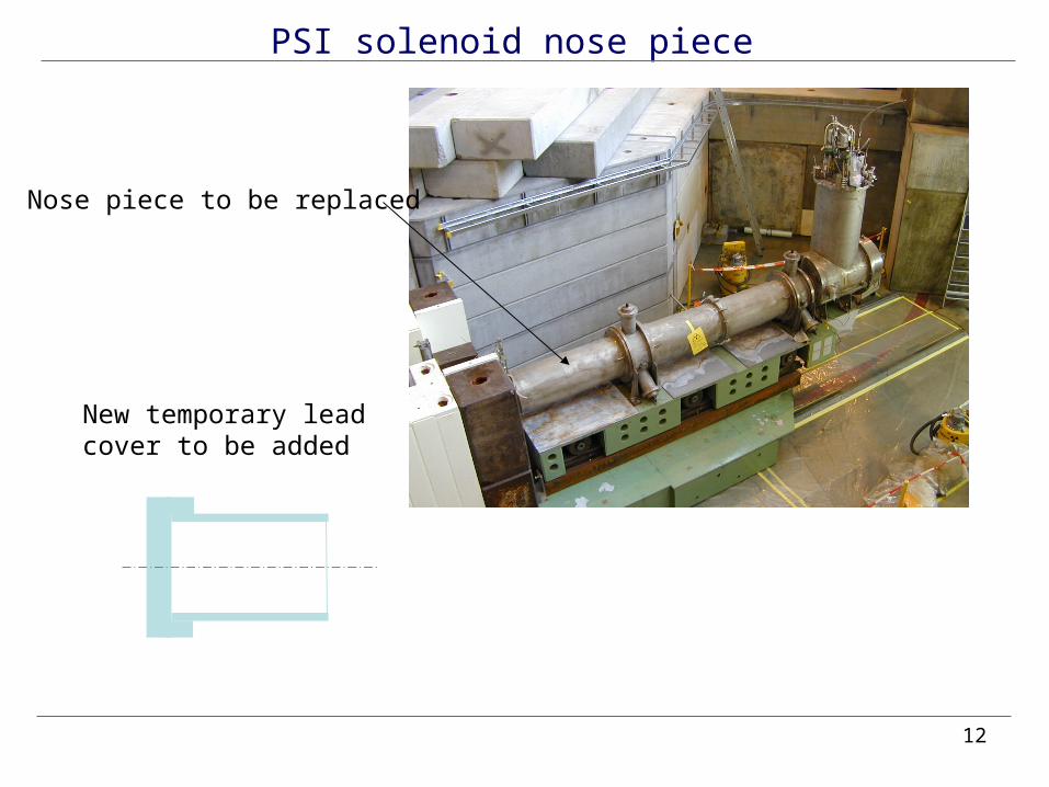
PSI solenoid nose piece
Nose piece to be replaced
New temporary leadcover to be added
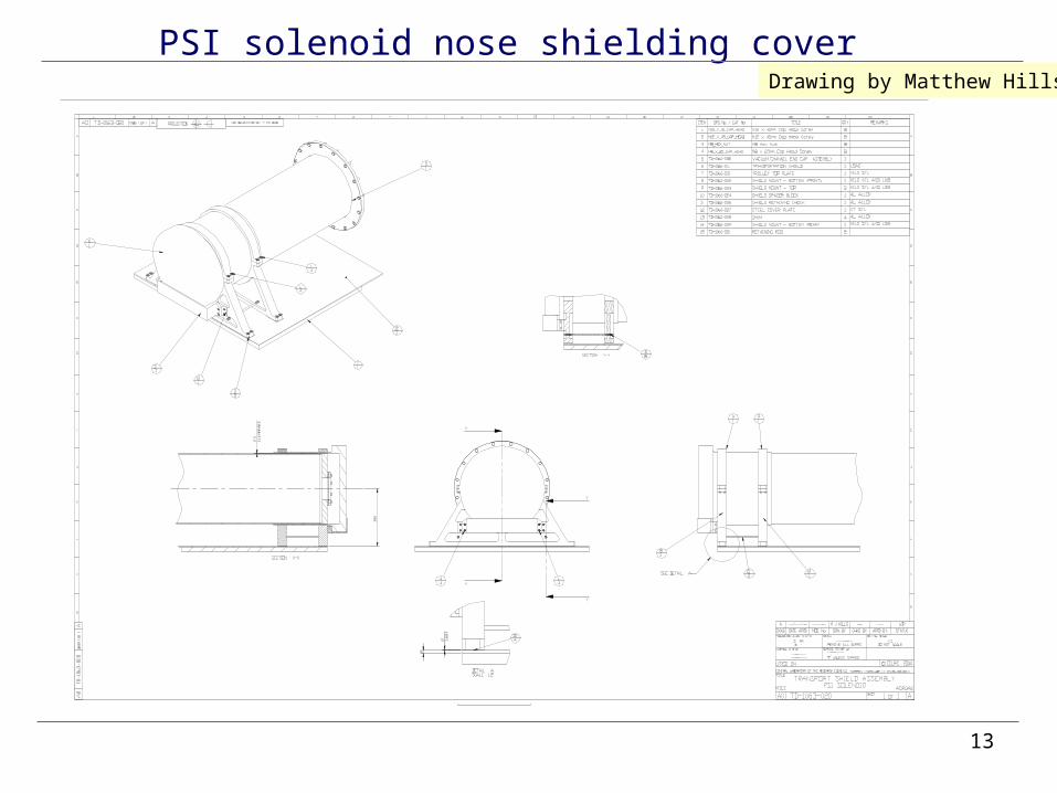
13
PSI solenoid nose shielding coverDrawing by Matthew Hills
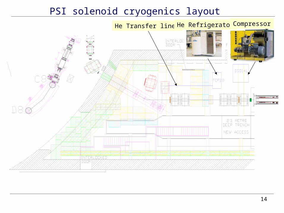
14
PSI solenoid cryogenics layoutHe Transfer lines He Refrigerator Compressor
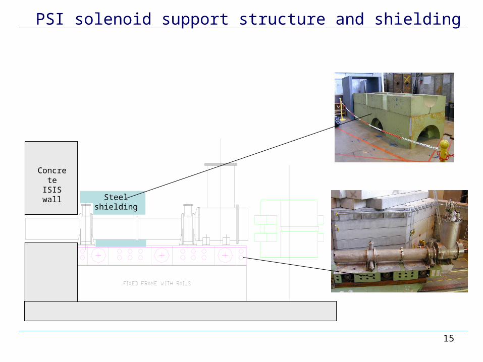
15
PSI solenoid support structure and shielding
Concrete ISIS wall
Steelshielding
16
Hall Layout: Plans
• Finalize shielding layout
(after the agreement with ISIS Radiation Safety Officer is reached)
• Add RF system infrastructure
• Modify layout for hydrogen system
• Add new support system (talk by Elwyn)