1. Introduction to Veri cation, Logic Representationsjaa/verification/lectures/1-2.pdf · ·...
29
Verification of Digital Systems, Spring 2018 1. Introductionto hardware verification and logic representations 1 1. Introduction to Verification, Logic Representations Jacob Abraham Department of Electrical and Computer Engineering The University of Texas at Austin Verification of Digital Systems Spring 2018 January 18, 2018 ECE Department, University of Texas at Austin Lecture 1. Introduction to Verification, Logic Representations Jacob Abraham, January 18, 2018 1 / 60 Goals of This Course Learn the principles of verification Verification is a key task in designing complex chips (as well as software and systems, for that matter) We will focus on digital hardware in this class Class will cover both simulation-based and formal verification Apply techniques from the lectures to designs in the lab Use commercial software (Cadence, Mentor Graphics) Formal equivalence checking Specification and application of assertions in simulation Formal verification of assertions ECE Department, University of Texas at Austin Lecture 1. Introduction to Verification, Logic Representations Jacob Abraham, January 18, 2018 1 / 60 Department of Electrical and Computer Engineering, The University of Texas at Austin J. A. Abraham, January 18, 2018
Transcript of 1. Introduction to Veri cation, Logic Representationsjaa/verification/lectures/1-2.pdf · ·...

Verification of Digital Systems, Spring 20181. Introductionto hardware verification and logic representations 1
40 60 80 100 120
40
60
80
mm
1. Introduction to Verification, LogicRepresentations
Jacob Abraham
Department of Electrical and Computer EngineeringThe University of Texas at Austin
Verification of Digital SystemsSpring 2018
January 18, 2018
ECE Department, University of Texas at AustinLecture 1. Introduction to Verification, Logic
Representations Jacob Abraham, January 18, 2018 1 / 60
40 60 80 100 120
40
60
80
mm
Goals of This Course
Learn the principles of verification
Verification is a key task in designing complex chips (as wellas software and systems, for that matter)
We will focus on digital hardware in this class
Class will cover both simulation-based and formal verification
Apply techniques from the lectures to designs in the lab
Use commercial software (Cadence, Mentor Graphics)
Formal equivalence checking
Specification and application of assertions in simulation
Formal verification of assertions
ECE Department, University of Texas at AustinLecture 1. Introduction to Verification, Logic
Representations Jacob Abraham, January 18, 2018 1 / 60
Department of Electrical and Computer Engineering, The University of Texas at AustinJ. A. Abraham, January 18, 2018
Verification of Digital Systems, Spring 20181. Introductionto hardware verification and logic representations 2
40 60 80 100 120
40
60
80
mm
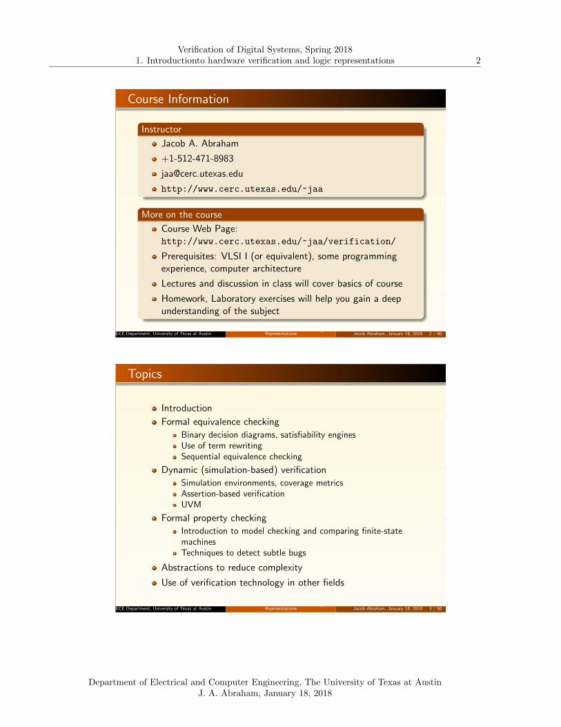
Course Information
Instructor
Jacob A. Abraham
+1-512-471-8983
http://www.cerc.utexas.edu/~jaa
More on the course
Course Web Page:http://www.cerc.utexas.edu/~jaa/verification/
Prerequisites: VLSI I (or equivalent), some programmingexperience, computer architecture
Lectures and discussion in class will cover basics of course
Homework, Laboratory exercises will help you gain a deepunderstanding of the subject
ECE Department, University of Texas at AustinLecture 1. Introduction to Verification, Logic
Representations Jacob Abraham, January 18, 2018 2 / 60
40 60 80 100 120
40
60
80
mm
Topics
Introduction
Formal equivalence checking
Binary decision diagrams, satisfiability enginesUse of term rewritingSequential equivalence checking
Dynamic (simulation-based) verification
Simulation environments, coverage metricsAssertion-based verificationUVM
Formal property checking
Introduction to model checking and comparing finite-statemachinesTechniques to detect subtle bugs
Abstractions to reduce complexity
Use of verification technology in other fields
ECE Department, University of Texas at AustinLecture 1. Introduction to Verification, Logic
Representations Jacob Abraham, January 18, 2018 3 / 60
Department of Electrical and Computer Engineering, The University of Texas at AustinJ. A. Abraham, January 18, 2018

Verification of Digital Systems, Spring 20181. Introductionto hardware verification and logic representations 3
40 60 80 100 120
40
60
80
mm
Work in the Course
Lectures
Cover fundamentals of the topicsNotes posted on the web pageSupplemental notes and papers on Canvas
Homework problems
Solve problems posted on Canvas
Laboratory exercises
Use commercial tools to apply techniques to realistic designs
Project
Your opportunity to delve into a verification-related topic ofinterest to you2 – 3 person teamsProject report and presentation to class at the end of thesemester
ECE Department, University of Texas at AustinLecture 1. Introduction to Verification, Logic
Representations Jacob Abraham, January 18, 2018 4 / 60
40 60 80 100 120
40
60
80
mm
Laboratory Exercises
Lab. 1 – Logic Equivalence Checking (LEC)
Formally check logical equivalence between a simple RTLmodule and its synthesized version
Example, after DFT insertion
Cadence Conformal LEC
Lab. 2 – Assertion Based Verification (ABV)
Add assertions to a testbench to verify that theimplementation correctly implements design intent
Document the functional coverage
Mentor Questa
ECE Department, University of Texas at AustinLecture 1. Introduction to Verification, Logic
Representations Jacob Abraham, January 18, 2018 5 / 60
Department of Electrical and Computer Engineering, The University of Texas at AustinJ. A. Abraham, January 18, 2018

Verification of Digital Systems, Spring 20181. Introductionto hardware verification and logic representations 4
40 60 80 100 120
40
60
80
mm
Laboratory Exercises, Cont’d
Lab. 3 – Universal Verification Methodology (UVM)
Standardized verification methodology
Testbench in SystemVerilog for a given design
Design tested for functional bugs
Mentor Questa
Lab. 4 – Formal Property Checking
Check specified properties in all possible states
Study effect of improperly specified properties
Techniques to detect subtle bugs: QED
Cadence JasperGold
ECE Department, University of Texas at AustinLecture 1. Introduction to Verification, Logic
Representations Jacob Abraham, January 18, 2018 6 / 60
40 60 80 100 120
40
60
80
mm
ProjectTopics
Research different areas in verification to pick a topic
Project can focus on a particular aspect of verification
Analysis and comparison of different verification techniquesApplication of verification to a real design (targets include theSUN OpenSparc (http://www.opensparc.net/), the IllinoisVerilog Model for the DEC Alpha (http://www.crhc.illinois.edu/ACS/tools/ivm/about.html),designs from http://www.opencores.org/projects/
including Amber ARM(http://opencores.org/project,amber), RISC-V(http://riscv.org/), Ridecore(https://github.com/ridecore/ridecore/), Pulpino(https://github.com/pulp-platform/pulpino) )
Presentation/Report
Team presents results to the class (during the last few classes)
A concise report on the project is due at the end of the courseECE Department, University of Texas at Austin
Lecture 1. Introduction to Verification, LogicRepresentations Jacob Abraham, January 18, 2018 7 / 60
Department of Electrical and Computer Engineering, The University of Texas at AustinJ. A. Abraham, January 18, 2018

Verification of Digital Systems, Spring 20181. Introductionto hardware verification and logic representations 5
40 60 80 100 120
40
60
80
mm
Reliability in the Life of an Integrated Circuit – I
Design
Design “bugs”Verification (Simulation, Formal)
Fabrication
Wafer
Process variations,defects
Process Monitors
ECE Department, University of Texas at AustinLecture 1. Introduction to Verification, Logic
Representations Jacob Abraham, January 18, 2018 8 / 60
40 60 80 100 120
40
60
80
mm
Reliability in the Life of an Integrated Circuit – II
Wafer Probe Package
Tester
Test cost,coverage
Design for Test,Built-In Self Test
System
Application
Test escapes,wearout,
environmentSystem Self-Test,Error Detection,Fault Tolerance
ECE Department, University of Texas at AustinLecture 1. Introduction to Verification, Logic
Representations Jacob Abraham, January 18, 2018 9 / 60
Department of Electrical and Computer Engineering, The University of Texas at AustinJ. A. Abraham, January 18, 2018

Verification of Digital Systems, Spring 20181. Introductionto hardware verification and logic representations 6
40 60 80 100 120
40
60
80
mm
Verification versus Validation – From IEEE “PMBOKguide”
Verification
“The evaluation of whether or not a product, service, or systemcomplies with a regulation, requirement, specification, or imposedcondition. It is often an internal process.”Are we designing the system right?
Validation
“The assurance that a product, service, or system meets the needsof the customer and other identified stakeholders. It often involvesacceptance and suitability with external customers.”Are we designing the right system?
ECE Department, University of Texas at AustinLecture 1. Introduction to Verification, Logic
Representations Jacob Abraham, January 18, 2018 10 / 60
40 60 80 100 120
40
60
80
mm
Historical Interest in Verification
A saga of “correct” software
In 1969, Naur published a technique for constructing andproving software, and applied it to a text processing problem
Informally proved correctness of about 25 lines of ALGOL 60
Leavenworth in a 1970 review pointed out that the first line ofthe output would be preceded by a blank unless the first wordhad exactly the maximum number of possible characters in aline (MAXPOS)
London found three additional faults in 1971 (e.g., procedurewould not terminate unless word with more than MAXPOScharacters encountered)
Presented a corrected version and proved it formally
Goodenough and Gerhart found three further faults in 1975that London had not detected (included the fact that the lastword would not be output unless it is followed by a BLANK orNIL)
ECE Department, University of Texas at AustinLecture 1. Introduction to Verification, Logic
Representations Jacob Abraham, January 18, 2018 11 / 60
Department of Electrical and Computer Engineering, The University of Texas at AustinJ. A. Abraham, January 18, 2018

Verification of Digital Systems, Spring 20181. Introductionto hardware verification and logic representations 7
40 60 80 100 120
40
60
80
mm
Historical Interest, Cont’d
A saga of “correct” software, Cont’d
Of the total of seven faults detected by the above researchers,four could have been detected simply by running theprocedure on test data!
Difficult to capture the specifications and requirementsagainst which an implementation is proved correct
National Computer Conference, 1978
Panel session: “Formal methods in programming – When willthey be practical?”
Don Knuth:
“Beware of bugs in the above code; I have only proved it correct,not tried it”
ECE Department, University of Texas at AustinLecture 1. Introduction to Verification, Logic
Representations Jacob Abraham, January 18, 2018 12 / 60
40 60 80 100 120
40
60
80
mm
Historical Interest in Verification, Cont’d
Hardware
J. Paul Roth, “Hardware Verification”, IEEE Transactions onComputers, December 1977.
ECE Department, University of Texas at AustinLecture 1. Introduction to Verification, Logic
Representations Jacob Abraham, January 18, 2018 13 / 60
Department of Electrical and Computer Engineering, The University of Texas at AustinJ. A. Abraham, January 18, 2018

Verification of Digital Systems, Spring 20181. Introductionto hardware verification and logic representations 8
40 60 80 100 120
40
60
80
mm
Analyzing Complex Designs
Need to (implicitly) search a very large state space
Find bugs in a design
Generate tests for faults in a manufactured chip
Basic algorithms for even combinational blocks (SAT, ATPG) areNP-complete Approaches to deal with real designs
Exploit hierarchy in the design
Develop abstractions for parts of a design
State-space explosion: A design with 300 state variables has morestates than the number of protons in the universe (1080)!
ECE Department, University of Texas at AustinLecture 1. Introduction to Verification, Logic
Representations Jacob Abraham, January 18, 2018 14 / 60
40 60 80 100 120
40
60
80
mm
The (In)Famous Pentium FDIV Problem
Graph of x, y, x/y in a small region by Larry Hoyle
ECE Department, University of Texas at AustinLecture 1. Introduction to Verification, Logic
Representations Jacob Abraham, January 18, 2018 15 / 60
Department of Electrical and Computer Engineering, The University of Texas at AustinJ. A. Abraham, January 18, 2018

Verification of Digital Systems, Spring 20181. Introductionto hardware verification and logic representations 9
40 60 80 100 120
40
60
80
mm
What is a “Bug”?
Design does not Match the Specification
One problem: complete (and consistent) specifications maynot exist for many products
For example, the difficulty in designing an X86 compatiblechip is not in implementing the X-86 instruction setarchitecture, but in matching the behavior with Intel chips
Something which the customer will complain about
“It’s not a bug, it’s a feature”
ECE Department, University of Texas at AustinLecture 1. Introduction to Verification, Logic
Representations Jacob Abraham, January 18, 2018 16 / 60
40 60 80 100 120
40
60
80
mm
Design Bug Distribution
Type of Bug %
“Goof” 12.7
Miscommunication 11.4
Microarchitecture 9.3
Logic/Microcode Changes 9.3
Corner Cases 8.0
Power Down 5.7
Documentation 4.4
Complexity 3.9
Initialization 3.4
Incorrect RTL Assertions 2.8
Design Mistake 2.6
Source: EE Times, July 4, 2001
42 Million Transistors
High-level description: 1+ millionlines of RTL
100 high-level bugs found throughformal verification
ECE Department, University of Texas at AustinLecture 1. Introduction to Verification, Logic
Representations Jacob Abraham, January 18, 2018 17 / 60
Department of Electrical and Computer Engineering, The University of Texas at AustinJ. A. Abraham, January 18, 2018

Verification of Digital Systems, Spring 20181. Introductionto hardware verification and logic representations 10
40 60 80 100 120
40
60
80
mm
Verification Consumes the Majority of Project Time
Source: Wilson Research Group and Mentor Graphics, 2014 Functional
Verification Study
ECE Department, University of Texas at AustinLecture 1. Introduction to Verification, Logic
Representations Jacob Abraham, January 18, 2018 18 / 60
40 60 80 100 120
40
60
80
mm
Many Projects Miss Schedule
Source: Mentor Graphics
ECE Department, University of Texas at AustinLecture 1. Introduction to Verification, Logic
Representations Jacob Abraham, January 18, 2018 19 / 60
Department of Electrical and Computer Engineering, The University of Texas at AustinJ. A. Abraham, January 18, 2018

Verification of Digital Systems, Spring 20181. Introductionto hardware verification and logic representations 11
40 60 80 100 120
40
60
80
mm
More Verification Engineers than Designers
Source: Wilson Research Group and Mentor Graphics, 2014 Functional
Verification Study
ECE Department, University of Texas at AustinLecture 1. Introduction to Verification, Logic
Representations Jacob Abraham, January 18, 2018 20 / 60
40 60 80 100 120
40
60
80
mm
Hardware Bugs Force Respins
Source: Wilson Research Group and Mentor Graphics, 2014 Functional
Verification Study
ECE Department, University of Texas at AustinLecture 1. Introduction to Verification, Logic
Representations Jacob Abraham, January 18, 2018 21 / 60
Department of Electrical and Computer Engineering, The University of Texas at AustinJ. A. Abraham, January 18, 2018

Verification of Digital Systems, Spring 20181. Introductionto hardware verification and logic representations 12
40 60 80 100 120
40
60
80
mm
Design and Implementation Verification
ECE Department, University of Texas at AustinLecture 1. Introduction to Verification, Logic
Representations Jacob Abraham, January 18, 2018 22 / 60
40 60 80 100 120
40
60
80
mm
Verification Approaches
Simulation (the most popular verification method)
Cycle based, functional simulation for billions of cyclesGood coverage metrics usually not availableAssertions used to specify behaviorEmulation
Capital intensiveMap design to be verified on FPGAsRun OS and application at MHz rates
Formal verification
Exhaustive verification of small modulesFormal equivalence checkingProperty checking
Techniques to manage complexity
Compositional techniquesMake use of symmetryAbstractions
ECE Department, University of Texas at AustinLecture 1. Introduction to Verification, Logic
Representations Jacob Abraham, January 18, 2018 23 / 60
Department of Electrical and Computer Engineering, The University of Texas at AustinJ. A. Abraham, January 18, 2018
Verification of Digital Systems, Spring 20181. Introductionto hardware verification and logic representations 13
40 60 80 100 120
40
60
80
mm
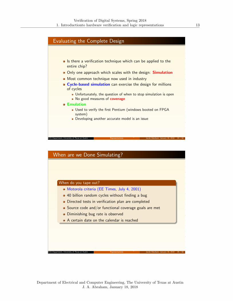
Evaluating the Complete Design
Is there a verification technique which can be applied to theentire chip?
Only one approach which scales with the design: Simulation
Most common technique now used in industry
Cycle-based simulation can exercise the design for millionsof cycles
Unfortunately, the question of when to stop simulation is openNo good measures of coverage
EmulationUsed to verify the first Pentium (windows booted on FPGAsystem)Developing another accurate model is an issue
ECE Department, University of Texas at AustinLecture 1. Introduction to Verification, Logic
Representations Jacob Abraham, January 18, 2018 24 / 60
40 60 80 100 120
40
60
80
mm
When are we Done Simulating?
When do you tape out?
Motorola criteria (EE Times, July 4, 2001)
40 billion random cycles without finding a bug
Directed tests in verification plan are completed
Source code and/or functional coverage goals are met
Diminishing bug rate is observed
A certain date on the calendar is reached
ECE Department, University of Texas at AustinLecture 1. Introduction to Verification, Logic
Representations Jacob Abraham, January 18, 2018 25 / 60
Department of Electrical and Computer Engineering, The University of Texas at AustinJ. A. Abraham, January 18, 2018

Verification of Digital Systems, Spring 20181. Introductionto hardware verification and logic representations 14
40 60 80 100 120
40
60
80
mm
Coverage-Driven Verification
Attempt to Verify that the Design Meets Verification Goals
Define all the verification goals up front in terms of“functional coverage points”
Each bit of functionality required to be tested in the design isdescribed in terms of events, values and combinations
Functional coverage points are coded into the verificationenvironment
Simulation runs can be measured for the coverage theyaccomplish
Focus on tests that will accomplishing the coverage(“coverage driven testing”)
Then fix bugs, release constraints, improve the testenvironmentMeasurable metric for verification effort
ECE Department, University of Texas at AustinLecture 1. Introduction to Verification, Logic
Representations Jacob Abraham, January 18, 2018 26 / 60
40 60 80 100 120
40
60
80
mm
Open Questions
Are There Better Measures of Coverage?
Coverage of statements in RTL would be a necessary but notsufficient
Coverage of all states is impractical even for a design with afew hundred state variables
Is there a way to identify a subset of state variables thatwould be tractable, and would lead to better bug detection?
How would these variables be related to the behavior of thedesign?
ECE Department, University of Texas at AustinLecture 1. Introduction to Verification, Logic
Representations Jacob Abraham, January 18, 2018 27 / 60
Department of Electrical and Computer Engineering, The University of Texas at AustinJ. A. Abraham, January 18, 2018

Verification of Digital Systems, Spring 20181. Introductionto hardware verification and logic representations 15
40 60 80 100 120
40
60
80
mm
Assertions
Assertions capture knowledge about how a design shouldbehave
Used in coverage-based verification techniques in a simulationenvironment as well as in formal verification
Assertions help to increase observability into a design, as wellas the controllability of a design
Each assertion specifies
legal behavior of some part of the design, orillegal behavior of part of the design
Examples of assertions (will be specified in a formal language)
The fifo should not overflowSome set of signals should be “one-hot”If a signal occurs, then . . .
ECE Department, University of Texas at AustinLecture 1. Introduction to Verification, Logic
Representations Jacob Abraham, January 18, 2018 28 / 60
40 60 80 100 120
40
60
80
mm
Simulation Monitors and Assertions
ECE Department, University of Texas at AustinLecture 1. Introduction to Verification, Logic
Representations Jacob Abraham, January 18, 2018 29 / 60
Department of Electrical and Computer Engineering, The University of Texas at AustinJ. A. Abraham, January 18, 2018

Verification of Digital Systems, Spring 20181. Introductionto hardware verification and logic representations 16
40 60 80 100 120
40
60
80
mm
Equivalence Checking
Validate that the implementation of a module is consistentwith the specification
Can use simulation or formal techniquesCombinational or sequential modules
Example: Specification in RTL
module mux(input s, d0, d1,
output y);
assign y = s ? d1 : d0;
endmodule
Example: Implementation at the gate level
ECE Department, University of Texas at AustinLecture 1. Introduction to Verification, Logic
Representations Jacob Abraham, January 18, 2018 30 / 60
40 60 80 100 120
40
60
80
mm
Huffman Model of a Sequential Circuit
If the specification and implementation have identical memoryelements, need to only check equivalence of the combinationalportions
ECE Department, University of Texas at AustinLecture 1. Introduction to Verification, Logic
Representations Jacob Abraham, January 18, 2018 31 / 60
Department of Electrical and Computer Engineering, The University of Texas at AustinJ. A. Abraham, January 18, 2018

Verification of Digital Systems, Spring 20181. Introductionto hardware verification and logic representations 17
40 60 80 100 120
40
60
80
mm
Formally Checking the Equivalence of Two Modules
Canonical representations for combinational equivalencechecking
TablesEquationsGraphs
Representations for sequential equivalence checking
State and transitionsTables, equations, graphs
Issues
ComplexityEase of automation
ECE Department, University of Texas at AustinLecture 1. Introduction to Verification, Logic
Representations Jacob Abraham, January 18, 2018 32 / 60
40 60 80 100 120
40
60
80
mm
Decision Tree for A⊕B ⊕ C
ECE Department, University of Texas at AustinLecture 1. Introduction to Verification, Logic
Representations Jacob Abraham, January 18, 2018 33 / 60
Department of Electrical and Computer Engineering, The University of Texas at AustinJ. A. Abraham, January 18, 2018

Verification of Digital Systems, Spring 20181. Introductionto hardware verification and logic representations 18
40 60 80 100 120
40
60
80
mm
Reduced, Ordered BDD (ROBDD)
F = A⊕B ⊕ CCanonical form
Structure and complexity of ROBDDs for Symmetric Functions?ECE Department, University of Texas at Austin
Lecture 1. Introduction to Verification, LogicRepresentations Jacob Abraham, January 18, 2018 34 / 60
40 60 80 100 120
40
60
80
mm
ROBDD Reduction
merge leaves with the same value;
for i:= n downto 1 do
for all nodes ν with Index(ν)=i do
if left(ν) = right(ν) then replace ν by left(ν);
if ∃ν ′.(Index(ν)=i and left(ν ′)=left(ν)
and right(ν ′)=right(ν))
then substitute ν by ν ′;
An algorithm for reducing the size of a graph representing afunction was first published by R. W. Payne, “Reticulation andother methods of reducing the size of printed diagnostic keys,”J. Gen. Microbiol., vol. 98, pp. 595-597, 1977.
ECE Department, University of Texas at AustinLecture 1. Introduction to Verification, Logic
Representations Jacob Abraham, January 18, 2018 35 / 60
Department of Electrical and Computer Engineering, The University of Texas at AustinJ. A. Abraham, January 18, 2018

Verification of Digital Systems, Spring 20181. Introductionto hardware verification and logic representations 19
40 60 80 100 120
40
60
80
mm
Example of ROBDD Reduction
ECE Department, University of Texas at AustinLecture 1. Introduction to Verification, Logic
Representations Jacob Abraham, January 18, 2018 36 / 60
40 60 80 100 120
40
60
80
mm
Operations on ROBDDs
This follows from Shannon expansion of f op g
Generate nodes of the result BDD recursivelyECE Department, University of Texas at Austin
Lecture 1. Introduction to Verification, LogicRepresentations Jacob Abraham, January 18, 2018 37 / 60
Department of Electrical and Computer Engineering, The University of Texas at AustinJ. A. Abraham, January 18, 2018

Verification of Digital Systems, Spring 20181. Introductionto hardware verification and logic representations 20
40 60 80 100 120
40
60
80
mm
Example of Combining Two ROBDDs
(x1 + x2) · (x2 · x3)
ECE Department, University of Texas at AustinLecture 1. Introduction to Verification, Logic
Representations Jacob Abraham, January 18, 2018 38 / 60
40 60 80 100 120
40
60
80
mm
Example of Combining Two ROBDDs, Cont’d
(x1 + x2) · (x2 · x3)
ECE Department, University of Texas at AustinLecture 1. Introduction to Verification, Logic
Representations Jacob Abraham, January 18, 2018 39 / 60
Department of Electrical and Computer Engineering, The University of Texas at AustinJ. A. Abraham, January 18, 2018

Verification of Digital Systems, Spring 20181. Introductionto hardware verification and logic representations 21
40 60 80 100 120
40
60
80
mm
Impact of BDD Variable Orderingf(x1, x2, . . . , x8) = x1 · x2 + x3 · x4 + x5 · x6 + x7 · x8
Ordering : x1 < x3 < x5 < x7 < x2 < x4 < x6 < x8
ECE Department, University of Texas at AustinLecture 1. Introduction to Verification, Logic
Representations Jacob Abraham, January 18, 2018 40 / 60
Figure modified
from Wikipedia
40 60 80 100 120
40
60
80
mm
Impact of BDD Variable Ordering, Cont’df(x1, x2, . . . , x8) = x1 · x2 + x3 · x4 + x5 · x6 + x7 · x8
Ordering : x1 < x2 < x3 < x4 < x5 < x6 < x7 < x8
ECE Department, University of Texas at AustinLecture 1. Introduction to Verification, Logic
Representations Jacob Abraham, January 18, 2018 41 / 60
Figure modified
from Wikipedia
Department of Electrical and Computer Engineering, The University of Texas at AustinJ. A. Abraham, January 18, 2018

Verification of Digital Systems, Spring 20181. Introductionto hardware verification and logic representations 22
40 60 80 100 120
40
60
80
mm
Variable Swapping – An example
Swap A and D
ECE Department, University of Texas at AustinLecture 1. Introduction to Verification, Logic
Representations Jacob Abraham, January 18, 2018 42 / 60
40 60 80 100 120
40
60
80
mm
Boolean Satisfiability (SAT)
Check if a Boolean function can be True (Satisfied)Find input values (Satisfying Assignment) that make thefunction True
First NP-complete problem (Cook, 1971)
Used in many different applications, including verification,Planning in AI, Theorem Proving, etc.
Commercial and Open SAT solvers available
Most verification tools now use BDDs + SAT
Some bring in ATPG ideas – called “structural SAT”
ECE Department, University of Texas at AustinLecture 1. Introduction to Verification, Logic
Representations Jacob Abraham, January 18, 2018 43 / 60
Department of Electrical and Computer Engineering, The University of Texas at AustinJ. A. Abraham, January 18, 2018

Verification of Digital Systems, Spring 20181. Introductionto hardware verification and logic representations 23
40 60 80 100 120
40
60
80
mm
Terminology
Literal: either a variable or the negation of a variable (xi, xi)
Clause: a disjunction of literals (a+ e+ f)
Conjunctive Normal Form (CNF)
Inputs to SAT solvers are usually represented in CNF(product-of-sums)
As compared with the Disjunctive Normal Form (DNF)(sum of products)
CNF is a conjunction of clauses
Example:(v + w + x)(x+ y + z)(v + w + y)(u+ v + y)(u+ v + x)
Most SAT solvers can exploit CNF
Easy to detect a conflictEasy to remember partial assignments that don’t work (justadd “conflict” clauses)
ECE Department, University of Texas at AustinLecture 1. Introduction to Verification, Logic
Representations Jacob Abraham, January 18, 2018 44 / 60
40 60 80 100 120
40
60
80
mm
Truth Table to CNF
Put negation of formula in DNF
For each “0” or “F” row in table, make a term equivalent tothe corresponding assignment
Negate the disjunction of the terms
By DeMorgan’s Law, switch AND and OR, and complementliterals
Example: Express x↔ y (x · y + x · y) in CNF
Two terms for “0”: x=1, y=0 and x=0, y=1=⇒ function is “0” when xy + xy
CNF is: (x+ y)(x+ y)
ECE Department, University of Texas at AustinLecture 1. Introduction to Verification, Logic
Representations Jacob Abraham, January 18, 2018 45 / 60
Department of Electrical and Computer Engineering, The University of Texas at AustinJ. A. Abraham, January 18, 2018

Verification of Digital Systems, Spring 20181. Introductionto hardware verification and logic representations 24
40 60 80 100 120
40
60
80
mm
Circuit to CNF
d ≡ (a+ b)
Clauses:(a+ b+ d)(a+ d)(b+ d)
e ≡ (c.d)
Clauses:(c+ d+ e)(d+ e)(c+ e)
ECE Department, University of Texas at AustinLecture 1. Introduction to Verification, Logic
Representations Jacob Abraham, January 18, 2018 46 / 60
40 60 80 100 120
40
60
80
mm
Satisfying Assignments
Assignment: Mapping of n variables to truth values
Example:(v + w + x)(x+ y + z)(v + w + y)(u+ v + y)(u+ v + x)One assignment:u = F, v = T, w = F, x = T, y = F, z = T(F ≡ 0, T ≡ 1)
Satisfying assignment (model): assignment which makes theformula evaluate to T (1)
Example: above function has 64 assignments, 31 satisfying(models)
Boolean formula is Valid (tautology) if all assignments aresatisfying
Boolean formula is Satisfiable if at least one assignment issatisfying
Boolean formula is Unsatisfiable if no assignment is satisfying
ECE Department, University of Texas at AustinLecture 1. Introduction to Verification, Logic
Representations Jacob Abraham, January 18, 2018 47 / 60
Department of Electrical and Computer Engineering, The University of Texas at AustinJ. A. Abraham, January 18, 2018

Verification of Digital Systems, Spring 20181. Introductionto hardware verification and logic representations 25
40 60 80 100 120
40
60
80
mm
Satisfiability Algorithms
Search for a satisfying assignment – assignment satisfyingeach clause
If some clause is 0, assignment failsBacktracking search
Simplified generic SAT algorithm
If all values are assigned, and no clauses violated, doneApply consistency checking, unit propagation, purification, . . .If unsatisfied clause, backtrackSelect variable to be assignedSelect value for the variableAssign variable and recurse
ECE Department, University of Texas at AustinLecture 1. Introduction to Verification, Logic
Representations Jacob Abraham, January 18, 2018 48 / 60
40 60 80 100 120
40
60
80
mm
Complexity Issues
k-SAT: A SAT problem with input in CNF with at most kliterals in each clause
2-SAT algorithm
Linear-time algorithm
3-SAT
NP-completeBest known deterministic upper bound on run time: 1.473n
Best known lower bound: n2.761
k-SAT can be reduced to 3-SAT
Horn-SAT: Clauses with at most one literal not negated
Useful for implication of one variable from a set of variablesx1 ∧ · · · ∧ xn → y leads to: x1 + · · ·+ xn + yCan be solved in Polynomial time (using unit propagation)
ECE Department, University of Texas at AustinLecture 1. Introduction to Verification, Logic
Representations Jacob Abraham, January 18, 2018 49 / 60
Department of Electrical and Computer Engineering, The University of Texas at AustinJ. A. Abraham, January 18, 2018

Verification of Digital Systems, Spring 20181. Introductionto hardware verification and logic representations 26
40 60 80 100 120
40
60
80
mm
DPLL (Davis-Putnam-Logemann-Loveland) Algorithms(pseudocode from Zhang/Malik paper on zChaff)
DPLL(formula, assignment) {
necessary = deduction(formula, assignment);
new_asgnmnt = union(necessary, assignment);
if (is_satisfied(formula, new_asgnmnt))
return SATISFIABLE;
else if (is_conflicting(formula, new_asgnmnt))
return CONFLICT;
var = choose_free_variable(formula, new_asgnmnt);
asgn1 = union(new_asgnmnt, assign(var,1));
if (DPLL(formula, asgn1)==SATISFIABLE)
return SATISFIABLE;
else {
asgn2 = union (new_asgnmnt, assign(var, 0));
return DPLL(formula, asgn2);
}
}
ECE Department, University of Texas at AustinLecture 1. Introduction to Verification, Logic
Representations Jacob Abraham, January 18, 2018 50 / 60
40 60 80 100 120
40
60
80
mm
International SAT Solver Competition
Jrvisalo et. al, “The International SAT Solver Competitions”, AI
Magazine, 2012ECE Department, University of Texas at Austin
Lecture 1. Introduction to Verification, LogicRepresentations Jacob Abraham, January 18, 2018 51 / 60
Department of Electrical and Computer Engineering, The University of Texas at AustinJ. A. Abraham, January 18, 2018

Verification of Digital Systems, Spring 20181. Introductionto hardware verification and logic representations 27
40 60 80 100 120
40
60
80
mm
Use of ATPG for Equivalence Checking
Use a tool which generates manufacturing tests
Detecting a “stuck-at-0” fault at Y (requires an input whichgenerates a 1 on Y) will prove inequivalence of the two circuits
Approach is not memory limited (like BDDs)
ECE Department, University of Texas at AustinLecture 1. Introduction to Verification, Logic
Representations Jacob Abraham, January 18, 2018 52 / 60
40 60 80 100 120
40
60
80
mm
Design Verification
Digital systems similar to reactive programsDigital systems receive inputs and produce outputs in acontinuous interaction with their environmentBehavior of digital systems is concurrent because each gate inthe system simultaneously evaluating its output as a functionof its inputs
Check Properties of Design
Since specification is usually not formal, check design forproperties that would be consistent with the specification
Safety “something bad will never happen”
Liveness Property: “something good will eventually happen”
Temporal Logic and variations commonly used to specifyproperties
Example: Linear Temporal Logic (LTL) or Computation TreeLogic (CTL)
ECE Department, University of Texas at AustinLecture 1. Introduction to Verification, Logic
Representations Jacob Abraham, January 18, 2018 53 / 60
Department of Electrical and Computer Engineering, The University of Texas at AustinJ. A. Abraham, January 18, 2018

Verification of Digital Systems, Spring 20181. Introductionto hardware verification and logic representations 28
40 60 80 100 120
40
60
80
mm
Example of Computation Tree
Traffic light controller
ECE Department, University of Texas at AustinLecture 1. Introduction to Verification, Logic
Representations Jacob Abraham, January 18, 2018 54 / 60
40 60 80 100 120
40
60
80
mm
Dealing with State Explosion
Verification is a Very Difficult Problem
Even combinational equivalence checking problems (ATPG,SAT) are NP-complete
Checking sequential properties is only possible for smalldesigns
Additional problem of generating correct “wrappers” for themodule being verified
How can we deal with the complexity?
Use more powerful computers?
Computers double in capability (assuming we can programmulti-core processors) every couple of yearsAdding one state variable to a design doubles its states
Exploit hierarchy in the design
Develop powerful abstractions
ECE Department, University of Texas at AustinLecture 1. Introduction to Verification, Logic
Representations Jacob Abraham, January 18, 2018 55 / 60
Department of Electrical and Computer Engineering, The University of Texas at AustinJ. A. Abraham, January 18, 2018

Verification of Digital Systems, Spring 20181. Introductionto hardware verification and logic representations 29
40 60 80 100 120
40
60
80
mm
Program Slicing
A Slice of a Design
Represents behavior of the design with respect to a given setof variables (or slicing criterion)
Proposed for use in software in 1984 (Weiser)
Slice generated by a control/data flow analysis of the programcode
Slicing is done on the structure of the design, so scales well
“Static analysis”
ECE Department, University of Texas at AustinLecture 1. Introduction to Verification, Logic
Representations Jacob Abraham, January 18, 2018 56 / 60
40 60 80 100 120
40
60
80
mm
Dramatic Example of Design Bug Detection and Recovery
BAE RAD750 (133 MHz) Science Lab on Mars
Mars Science Laboratory – MSL (“Curiosity”) reliesextensively on BAE RAD750 chip running at 133 MHzDuring cruise to Mars (circa January 2012), MSL processesare unexpectedly reset – no code bug is found (7 monthsremaining before landing)Misbehavior eventually traced to processor hardwaremalfunction: instruction flow depends on processortemperatureOnly possible fix was via software – done successfully
ECE Department, University of Texas at AustinLecture 1. Introduction to Verification, Logic
Representations Jacob Abraham, January 18, 2018 57 / 60
Department of Electrical and Computer Engineering, The University of Texas at AustinJ. A. Abraham, January 18, 2018