1 H ardware D escription L anguages Modeling Digital Systems.
27
1 Hardware Description Languages Modeling Digital Systems
-
Upload
brooke-sybil-barton -
Category
Documents
-
view
212 -
download
0
Transcript of 1 H ardware D escription L anguages Modeling Digital Systems.

1
HardwareDescriptionLanguages
Modeling Digital Systems

2
HDL coding Styles
Register Transfer Level Structural Behavioral
Be careful NOT everybody givesthe same meaning to the term BEHAVIORAL !

3
HDL applications
High Level Modeling (Behavioral style) Design Entry (Structural & RTL styles) Simulation (Behavioral style)
Validation by mean of a test bench
generate stimuli
observeresponses
instantiatedesign to
test
dut.vhd
TESTBENCH
dut_tb.vhd

4
Levels of Abstraction
Behavioral
RTL
Structural

5
Behavioral Level
Describe behavior (functionality and performances)
All language features can be used

6
Register Transfer Level
Only a small subset of the Language statements can be mapped into “Silicon”.
translationHDL code
generic technology
unoptimizedgenericboolean netlist optimization
& mapping
target technology
area and timing
constraints
optimizedgate level netlist
SYNTHESIS

7
Structural Level
Sub-Modules interconnection Primitive cells interconnection (net-list) The code describes a bunch of port mappings.

8
Describing Systems
What aspects do we need to consider to describe a digital system ?
Interface Function Performance (delay/area/costs/…)

9
What elements should be in a VHDL description? (1)
VHDL was conceived for the description of digital systems Keeping in mind the pragmatic issues of design re-use and
portability of descriptions Portability across technologies
Attributes of digital systems served as the starting point Language features were designed to capture the key
attributes

10
What elements should be in a VHDL description? (2)
Descriptions should support multiple levels of abstraction The elements should enable meaningful and accurate
simulation of hardware described using the elements Elements should have attributes of time as well as function
The elements should enable the generation of hardware elements that realize a correct physical implementation Existence of a mapping from elements to VLSI devices

11
Attributes of Digital Systems
Digital systems are about: signals and their values events, propagation delays, concurrency Time ordered sequence of events produces a waveform
10 15 20 25 30 35 40
a
b
sum
carry
5Time (ns)
Event
ab
sum
carry

12
Attributes of Digital Systems: Timing
Timing: computation of events takes place at specific points in time Need to wait for an event: in this case the clock Timing is an attribute of both synchronous and asynchronous systems
D
Clk
S
Q
R
10 15 20 25 30 35 40
Clk
D
Q
Time (ns)
Triggeringedge
Q

13
Attributes of Digital Systems: Timing
Asynchronous communication does not have a global clock Still need to wait for events on specific signals
TRANSMIT
ACK

14
Attributes of Digital Systems: Signal Values
possible
signal values
• We associate logical values with the state of a signal• Signal Values: IEEE 1164 Value System
Value Interpretation
U Uninitialized
X Strong Unknown
0 Strong 0
1 Strong 1
Z High Impedance
W Weak Unknown
L Weak 0
H Weak 1
- Don’t Care
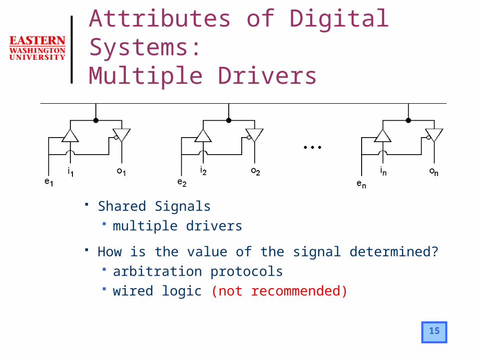
15
Attributes of Digital Systems: Multiple Drivers
Shared Signals multiple drivers
How is the value of the signal determined? arbitration protocols wired logic (not recommended)

16
Tristate Inverter

17
Modeling Digital Systems
We seek to describe attributes of digital systems common to multiple levels of abstractionevents, propagation delays, concurrencywaveforms and timing signal valuesshared signals

18
Modeling Digital Systems
Hardware description languages must provide constructs for naturally describing these attributes of a specific designsimulators use such descriptions for
“mimicking” the physical systemsynthesis compilers use such descriptions for
synthesizing manufacturable hardware specifications that conform to this description

19
Execution of VHDL models For Simulation
Discrete event simulator For Synthesis
Hardware inferenceThe resulting circuit is a function of the building
blocks used for implementation and the optimization goal
• Primitives: e.g. NAND vs. NOR• Cost/performance objectives

20
Simulation of Digital Systems
Digital systems are modeled as the generation of events (= value transitions) on signals Discrete event simulations manage the generation and ordering of events
Correct sequencing of event processing Correct sequencing of computations caused by events
@5 ns
@10 ns
@15 ns
@5 ns
v1v2@5ns
v3v4@10ns
v5v6@15ns
Head
0

Discrete Event Simulation: Example
10
a@5ns
U1
carry@5ns
U0
sum@5ns
01
sum@10ns
10
carry@10ns01
a@10ns
10
b@10ns
10
a@15ns
5ns
10ns
10ns
Initial state: a = b = 1, sum = carry = UEvent List HeadSimulation Time
0ns U1
carry@5nsU0
sum@5ns New event generated from inputUpdate
time
Update signal values, execute, generate new events, update time
Update signal values, execute, generate new events
10 15 20 25 30 35 40
a
b
sum
carry
5
Event
b
a sum
carry

22
Discrete Event Simulation
Management of simulation time: ordering of events
Two step model of the progression of timeEvaluate all affected components at the current time:
events on input signalsSchedule future events and move to the next time step:
the next time at which events take place

23
Simulation Modeling
VHDL programs describe the generation of events in digital systems Discrete event simulator manages event ordering and progression of time Accuracy vs. time trade-offs
Greater detail more events greater accuracy Less detail smaller number of events faster simulation speed
b
a sum
carry
VHDL Model
compiler
Discrete Event Simulator

24
Synthesis and Hardware Inference
Synthesis compiler
HDLDesign Specification

25
Summary
VHDL is used to describe digital systems and hence has language constructs for the following key attributesEvents, propagation delays, and concurrencyTiming, and waveformsSignal values and use of multiple drivers for a
signal

26
Summary
VHDL has an underlying discrete event simulation modelModel the generation of events on signalsBuilt in mechanisms for managing events and
the progression of timeDesigner simply focuses on writing accurate
descriptions

27
VHDL Design Organization
Entitythe “symbol” interface (input/output ports)
Architectureone of the several possible implementation of the design
Configurationbinding between the symbol and one of the many possible implementation. Can be used to express hierarchy.


![D escription phys power point [autoguardado]2](https://static.fdocuments.us/doc/165x107/55d73552bb61eb074f8b45b4/d-escription-phys-power-point-autoguardado2.jpg)