1 Data Transmission and Computer Networks Data Link Layer.
40
1 Data Transmission and Computer Networks Data Link Layer
-
date post
19-Dec-2015 -
Category
Documents
-
view
217 -
download
0
Transcript of 1 Data Transmission and Computer Networks Data Link Layer.

1
Data Transmission and Computer Networks
Data Link Layer

2
The data link layer transmits raw bits into a line that appears free of transmission errors to the network layer.
The Data Link Layer Tasks:
Bits Error Detection and Corrections Point-to-point Error Control:
a frame may be destroyed, an acknowledgement frames may get lost, a duplicate frame may be produced. , a frame may be out of sequence ….etc
Point-to-point flow control: mechanism employed to prevent a fast transmitter from drowning a slow receiver in data.
Framing:It creates and recognizes frame boundaries.
DATA LINK LAYER

3
The Data Link Layer Tasks:
Devices Interfacing
Medium Access Control (MAC)
To allow multiple devices share a common link
Addressing
To define address of each device connected to the link
Line configurations :
To define transmission & communication modes and transmission techniques.
DATA LINK LAYER

4
Transmission Techniques1.Parallel Transmission

5
2.Serial Transmission

6
When data is transmitted between two pieces of equipment, three communication modes of operation can be used.
Simplex: Data is to be transmitted in one direction only.
Half-Duplex: This is used when two interconnected devices which to interchange information alternately.
Duplex or full-Duplex: This is used when data is to be exchanged between two connected devices in both directions simultaneously.
Communication Modes

7
For the receiving device to interpret the bit pattern correctly, it must be able to determine the following:
Bit Synchronization: The start of each bit cell period (in order to sample the incoming signal in the middle of the bit cell). Character Synchronization: The start and end of each character or byte. Frame Synchronization: The start and end of each complete message block (frame).
Two transmission modes to accomplish synchronization : 1. Asynchronous Transmission. 2. Synchronous Transmission.
Transmission Modes

8
In asynchronous transmission, the receiver clock (R×C) runs unsynchronized with respect to the incoming signal (R×D).
Each character (byte) is encapsulated between an additional start bit and one or more stop bits.
The state of the signal on the transmission line between characters is idle state.
1 .Asynchronous Transmission

9
Standard Interchange Codes1. American Standards Committee for Information Interchange
(ASCII):Bit
Positions
700001111600110011501010101
43210000NULDLESP0@P\p0001SOHDC1!1AQaq0010STXDC2”2BRbr0011ETXDC3#3CScs0100EOTDC4$4DTdt0101ENQNAK%5EUeu0110ACKSYN&6FVfv0111BELETB’7GWgw1000BSCAN(8HXhx1001HTEM)9IYiy1010LFSUB*:JZjz1011VTESC+;K[k{1100FFFS,<L\l|1101CRGS-=M]m}1110SORS.>N^n~1111SIUS/?O_oDEL

10
Standard Interchange Codes1. Extended Binary Coded Decimal Interchange Code (EBCDIC):
Bit
Positions
80000000011111111700001111000011116001100110011001150101010101010101
43210000NULDLEDSSP&-00001SOHDC1SOS/ajAJ10010STXDC2FSSYNbksBKS20011ETXDC3cltCLT30100PFRESBYPPNdmuDMU40101HTNLLFRSenvENV50110LCBSEOBUCfowFOW60111DELILPREEOTgpxGPX71000CANhqyHQY81001EMirzINZ91010SMMCCSM¢!:1011VT.$’#1100FFIFSDC4<*%@1101CRIGSENQNAK()-,1110SOIRSACK+;>=1111SIIUSBELSUB|¬?”

11
1 .Asynchronous Transmission
Example 3.1:Construct the transmitted frame using asynchronous transmission mode which contains the following data: GO. Assume that the number of stop bits is 2 and parity bit is used.
PO PETXSTX P PG

12
1 .Asynchronous Transmission
Example :Construct the transmitted frame using asynchronous transmission mode which contains the following data: YES. Assume that the number of stop bits is 1 and no parity bit is used.
STX Y E ETXS

13
1 .Asynchronous Transmission
Example :
Assuming asynchronous transmission mode is used with 8-bit character, a parity bit, two stop bits, and transfer rate 14400 bps. Calculate the following:
1. Size of the transmitted element (in bits) which contains one character.
2. Time duration for each bit .
3. Maximum number of characters that can be transmitted per second.
Solution of Example :
1. Size of transmitted element = 1 + 8 + 2 + 1 = 12 bits.
2. Time duration for each bit = 1 / 14400 sec.
3. Max. number of char per second = 14400 / 12 = 1200 char/sec.
4.0 Efficiency = 8/12 = 66.6 %

14
Character Synchronization using Asynchronous Transmission:
After the start bit is detected, the receiver achieves character synchronization simply by counting the programmed number of bits.
1 .Asynchronous Transmission

15
Frame synchronization is used to determine the start and end of frame.
Case I: Printable Characters
Encapsulate the complete block between two non-printable characters: STX (start-of-text) and ETX (end-of-text).
Case II: Binary Data
When transmitting binary data, STX and ETX are preceded by another control character known as Data Link Escape (DLE).
Framing using Asynchronous Transmission:

16
Frame Synchronization using Asynchronous Transmission:To transmit binary data:The binary file may contain ETX character which would cause the receiver to
terminate reception abnormally. For this , the following steps are takenStep 1: When transmitting binary data, STX and ETX are preceded by another
control character known as Data Link Escape (DLE). Step 2: After transmitting the start of frame sequence (DLE-STX), the transmitter
inspects each byte in frame prior to transmission to determine if it is a DLE character. If it is, a second DLE character is transmitted before the next byte.
Step 3: Step 2 is repeated until the appropriate number of bytes have been transmitted. The transmitter then transmits the unique DLE-ETX sequence.
To receive binary data: When the receiver receives a DLE, it checks the next character. If the next
character is another DLE, the receiver discards it and waits for the next byte. If it is an ETX, then it terminates reception process.
Framing

17
Frame Synchronization using Asynchronous Transmission:
Case I: For Printable Characters
1 .Asynchronous Transmission

18
Frame Synchronization using Asynchronous Transmission:
Case II: For Binary Data
1 .Asynchronous Transmission

19
Example :Construct the transmitted frame using asynchronous transmission mode which contains the following data: A B DLE ETX Z.
Assume that the number of stop bits is 1 and no parity bit is used.
1 .Asynchronous Transmission
DLE STX A B DLE DLE
ETX Z DLE ETX

20
Example :Construct the transmitted frame using asynchronous transmission mode which contains the following data: R DLE DLE ETX I DLE.
Assume that the number of stop bits is 1 and no parity bit is used.
1 .Asynchronous Transmission
DLE STX R DLE DLE DLE DLE ETX
I DLE DLE DLE DLE

21
The complete block or frame of data is transmitted as a contiguous stream with no delay between each 8-bit element.
To enable the receiving device to achieve synchronization:
The transmitted bit stream is suitably encoded.
All frames are preceded by two or more reserved bytes or characters.
The content of each frame is encapsulated between a pair of reserved characters.
2 .Synchronous Transmission

22
There are two schemes to achieve character and frame synchronization in the synchronous transmission:
Character-Oriented Synchronous Transmission
Bit-Oriented Synchronous Transmission
Both use the same bit synchronization method.
Framing in Synchronous Transmission

23
I. Character-Oriented Synchronous Transmission:
The transmitter adds two or more transmission control characters known as Synchronous Idle or (SYN) characters before each block of characters.
SYN characters are used to allow receiver to maintain bit synchronization.
2 .Synchronous Transmission

24
I. Character-Oriented Synchronous Transmission:
Once this has been done, they allow the receiver to start interpret the received bit stream on the correct character boundaries - Character Synchronization.
The frame synchronization is achieved by encapsulating the block of characters between STX and ETX pair for the case of the text transmission, and the start-of-frame sequence (DLE-STX) and the end-of-frame sequence (DLE-ETX) for the case of the binary transmission.
2 .Synchronous Transmission

25
I. Character-Oriented Synchronous Transmission:
Case 1: Printable characters:
Case 2: Binary data:
2 .Synchronous Transmission

26
II. Bit-Oriented Synchronous Transmission: Character-oriented transmission is inefficient for transmission binary data because it performs too much DLE stuffing. Therefore, alternative synchronous transmission scheme is used – Bit-Oriented Synchronous Transmission.
In Bit-Oriented Synchronous Transmission, the transmitter sends a string of idle bytes (each compromising 01111111) preceding the opening flag (01111110).
When the receiver gets the opening flag, the frame contents are read and interpreted on 8-bit boundaries until the closing flag (01111110) is detected. The reception process is then terminated.
2 .Synchronous Transmission

27
II. Bit-Oriented Synchronous Transmission:
2 .Synchronous Transmission

28
II. Bit-Oriented Synchronous Transmission:
To achieve data transparency with this scheme, we must ensure the flag pattern is not present in the frame contents. We can do this by bit Stuffing.
The bit stuffing technique is to detect a sequence of 5 contiguous binary 1 digits in the transmitted frame contents, then automatically inserts an additional binary 0 digit.
In this way, the flag pattern 01111110 can never be present in the frame contents between the opening and closing flag.
2 .Synchronous Transmission

29
Example :Deduce the number of additional bits required to transmit a text message comprising 100 of 8-bit characters over a data link using each of the following transmission control schemes:Case 1: Asynchronous with two stop bits per character.
Char1
STXChar
2Char100
ETX

30
Example (Continued):Case 2: Synchronous with two synchronization characters.
2 .Synchronous Transmission
Char 1SYN STX Char 2 Char 100SYN ETX

31
II. Bit-Oriented Synchronous Transmission:
Example 3.8:
Assume Bit-Oriented Synchronous Transmission is to be used. Construct the transmitted frame, which contains the binary data:
1 1 0 1 1 0 0 1 1 1 1 1 1 0 0 1 1 1 1 1 0 1 1.
Solution of Example 3.8:
2 .Synchronous Transmission
32
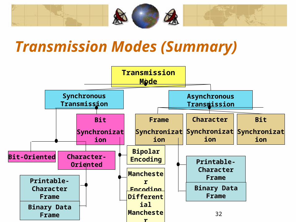
Transmission Modes (Summary)
Transmission Mode
Asynchronous TransmissionSynchronous Transmission
Bit
Synchronization
Character
Synchronization
Frame
Synchronization
Bit
Synchronization
Bit-Oriented Character-OrientedPrintable- Character
Frame
Bipolar Encoding
Manchester Encoding
Differential Manchester Encoding
Binary Data FramePrintable- Character
Frame
Binary Data Frame

33
There are two approaches for achieving bit error control:
Forward error control, in which the receiver cannot only detect when error are present but also determine where in the received bit stream the errors are. The correct data is then obtained by inverting these bits.
Feedback (backward) error control, in which the receiver detects when errors are present but not their location. A retransmission control scheme is used to request that another copy of information to be sent.
Bit Error Control

34
I. Parity:
1 .Feedback (Backward) Error Control

35
I. Parity:
1 .Feedback (Backward) Error Control

36
II. Vertical Redundancy Check (VRC):
1 .Feedback (Backward) Error Control

37
III. Cyclic Redundancy Check (CRC) :
1 .Feedback (Backward) Error Control

38
III. Cyclic Redundancy Check (CRC) :
Example :
A series of 8-bit message blocks (frames) is to be transmitted across a data link using a CRC for error control. A generator polynomial of 11001 is to be used. Use an example to illustrate the following:
(a) The FCS generation process.
(b) The FCS checking process.
1 .Feedback (Backward) Error Control

39
III. Cyclic Redundancy Check (CRC) :
Solution of Example :
(a)The FCS generation process.
1 .Feedback (Backward) Error Control

40
III. Cyclic Redundancy Check (CRC) :
Solution of Example 3.9:
(b) The FCS checking process.
1 .Feedback (Backward) Error Control