Physical layer OSI Model & Transmission Media
27
Physical Layer Mukesh Chinta Asst Prof, CSE, VRSEC
-
Upload
v-r-siddhartha-engineering-college -
Category
Engineering
-
view
420 -
download
3
Transcript of Physical layer OSI Model & Transmission Media

Physical Layer
Mukesh Chinta
Asst Prof, CSE, VRSEC

Physical Layer
• The physical layer is the first layer of the Open System
Interconnection Model (OSI Model). The physical layer deals
with bit-level transmission between different devices and
supports electrical or mechanical interfaces connecting to the
physical medium for synchronized communication.
2

Data & Signals• Data refers to information that conveys some meaning based on some
mutually agreed up rules or conventions between a sender and a receiver and
today it comes in a variety of forms such as text, graphics, audio, video and
animation
• Data can be of two types; analog and digital. Analog data take on continuous
values on some interval. Typical examples of analog data are voice and video.
On the contrary, digital data take on discrete values. Text or character strings
can be considered as examples of digital data.
• Signal is electrical, electronic or optical representation of data, which can be
sent over a communication medium. Stated in mathematical terms, a signal is
merely a function of the data. Analog signals are continuous-valued; digital
signals are discrete-valued.
3
Periodic/aperiodic Signals
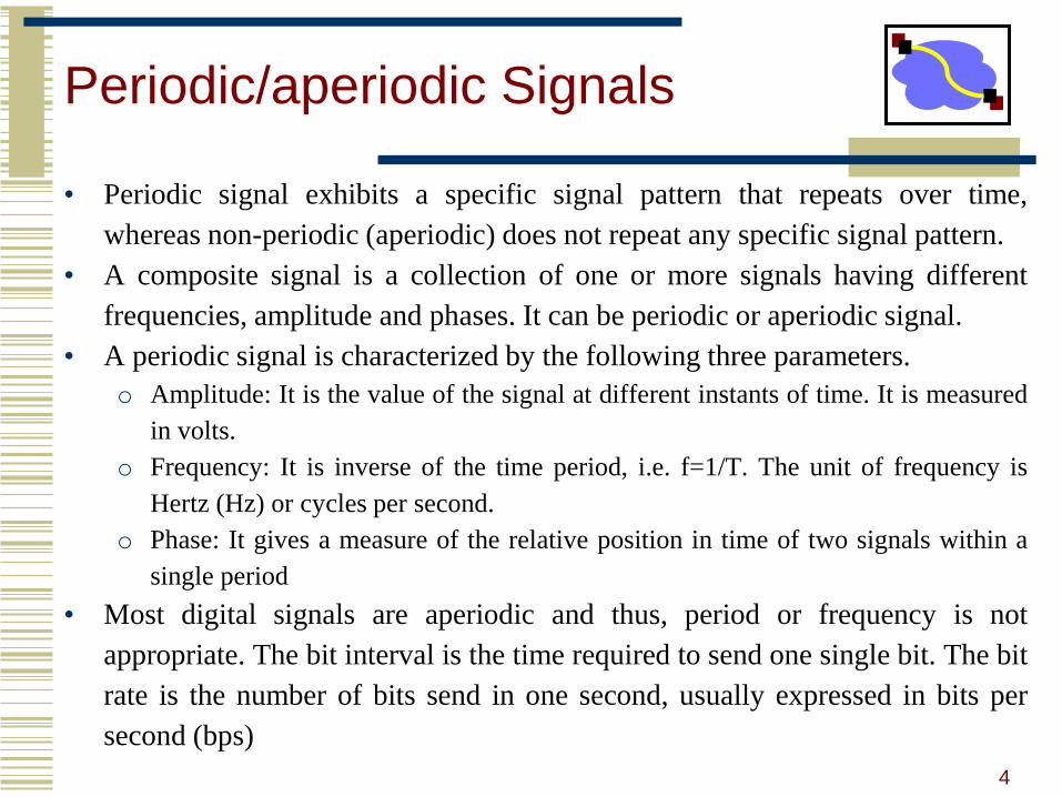
• Periodic signal exhibits a specific signal pattern that repeats over time,
whereas non-periodic (aperiodic) does not repeat any specific signal pattern.
• A composite signal is a collection of one or more signals having different
frequencies, amplitude and phases. It can be periodic or aperiodic signal.
• A periodic signal is characterized by the following three parameters.
o Amplitude: It is the value of the signal at different instants of time. It is measured
in volts.
o Frequency: It is inverse of the time period, i.e. f=1/T. The unit of frequency is
Hertz (Hz) or cycles per second.
o Phase: It gives a measure of the relative position in time of two signals within a
single period
• Most digital signals are aperiodic and thus, period or frequency is not
appropriate. The bit interval is the time required to send one single bit. The bit
rate is the number of bits send in one second, usually expressed in bits per
second (bps)
4

Physical Layer - Standards
• The protocols and operations of the upper OSI layers are performed by
software and are designed by software engineers
• The services and protocols in the TCP/IP suite are defined by the Internet
Engineering Task Force (IETF). Similar to technologies associated with the
Data Link layer, the Physical layer technologies are defined by organizations
such as:
1. The International Organization for Standardization (ISO)
2. The Institute of Electrical and Electronics Engineers (IEEE)
3. The American National Standards Institute (ANSI)
4. The International Telecommunication Union (ITU)
5. The Electronics Industry Alliance/Telecommunications Industry Association
(EIA/TIA)
6. National telecommunications authorities such as the Federal Communication
Commission (FCC) in the USA.
5
Physical Layer
6
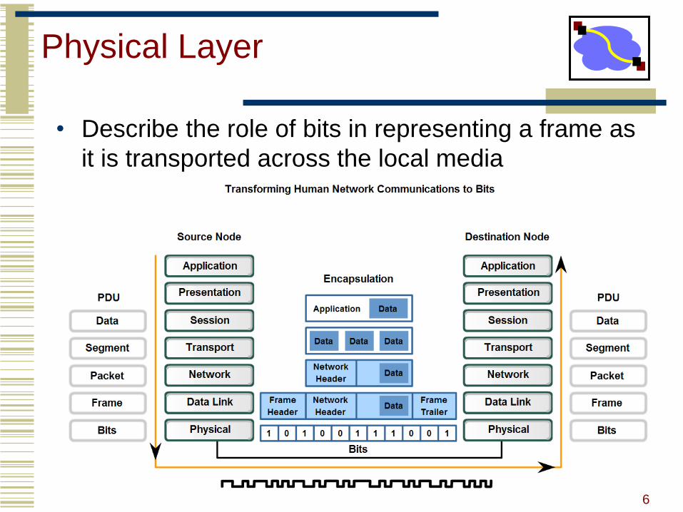
• Describe the role of bits in representing a frame as
it is transported across the local media

Signals on Physical Media
7

Physical Media Data Rates
Different physical media support the transfer of bits at different speeds. Data
transfer can be measured in three ways:
• Bandwidth: The capacity of a medium to carry data is described as the raw
data bandwidth of the media. Digital bandwidth measures the amount of
information that can flow from one place to another in a given amount of
time. Bandwidth is typically measured in kilobits per second (kbps) or
megabits per second (Mbps).
• Throughput: Throughput is the measure of the transfer of bits across the
media over a given period of time. Due to a number of factors, throughput
usually does not match the specified bandwidth in Physical layer
implementations such as Ethernet.
• Goodput: A third measurement has been created to measure the transfer of
usable data. Goodput is the measure of usable data transferred over a given
period of time, and is therefore the measure that is of most interest to network
users.8

Data Rates
9
The range of frequencies transmitted without being strongly
attenuated is called the bandwidth

10
Maximum Data Rate of a Channel
Nyquist theorem: To transmit at a transmission rate of fb Hz requires aminimum bandwidth of Hmin = fb/2 Hz→ This specifies the maximum data rate for the noiseless case as:
Where, V is the number of discrete levels in the signal and H is the
maximum bandwidth.
Shannon’s theorem: If information rate does not exceed channel capacity,there exists a coding technique such that information can be transmitted over anoisy channel, error free.The channel capacity provides the maximum possible data rate for the generalnoisy case as:

Examples
11
Consider a noiseless channel with a bandwidth of 3000 Hz transmitting a signal
with two signal levels. The maximum bit rate can be calculated as
We can calculate the theoretical highest bit rate of a regular telephone line. A
telephone line normally has a bandwidth of 3000. The signal-to-noise ratio is
usually 3162. For this channel the capacity is calculated as
The signal-to-noise ratio is often given in decibels. Assume that SNRdB = 36
and the channel bandwidth is 2 MHz. The theoretical channel capacity can be
calculated as

Transmission Media
12
۞Transmission media are actually located below the physical layer and are
directly controlled by the physical layer.
۞A transmissionmedium can be broadly defined as anything that can carryinformation from a source to a destination.۞In data communications, the transmission medium is usually free space,metallic cable, or fiber-optic cable. The information is usually a signal that isthe result of a conversion of data from another form.

Guided Media
• Guided media, which are those that provide a conduit from one
device to another, include twisted-pair cable, coaxial cable, and
fiber-optic cable.
• A signal traveling along any of these media is directed and
contained by the physical limits of the medium.
• Twisted-pair and coaxial cable use metallic (copper) conductors
that accept and transport signals in the form of electric current.
• Optical fiber is a cable that accepts and transports signals in the
form of light.
13

Magnetic Media
• One of the most common ways to transport data from one computer to
another is to write them onto magnetic tape or removable media (e.g.,
recordable DVDs), physically transport the tape or disks to the destination
machine, and read them back in again.
• It is often more cost effective, especially for applications in which high
bandwidth or cost per bit transported is the key factor.
• Although the bandwidth characteristics of magnetic tape are excellent, the
delay characteristics are poor. Transmission time is measured in minutes or
hours, not milliseconds.
14
Twisted Pair
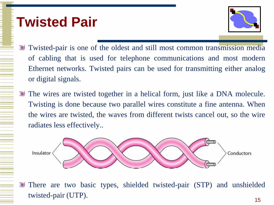
Twisted-pair is one of the oldest and still most common transmission media
of cabling that is used for telephone communications and most modern
Ethernet networks. Twisted pairs can be used for transmitting either analog
or digital signals.
The wires are twisted together in a helical form, just like a DNA molecule.
Twisting is done because two parallel wires constitute a fine antenna. When
the wires are twisted, the waves from different twists cancel out, so the wire
radiates less effectively..
There are two basic types, shielded twisted-pair (STP) and unshielded
twisted-pair (UTP).15

UTP
The most common twisted-pair cable used in communications is referred to as
unshielded twisted-pair (UTP).
This cable consists of 4 twisted pairs of metal wires (that means there are 8 wires in
the cable). Each pair is twisted with a different number of twists per inch to help
eliminate interference from adjacent pairs and other electrical devices. Each twisted
pair consists of two metal conductors that are insulated separately with their own
coloured plastic insulation.
16

Categories of UTP
17
Category rating based on number of twists per inch andthe material used

STP
• This cable has a metal foil or braided-mesh covering that covers each pair of
insulated conductors. The metal foil is used to prevent infiltration of
electromagnetic noise. This shield also helps to eliminate crosstalk.
18
STP is suited for environments with electrical interference and also provides
better performance at higher data rates. But the extra shielding makes the STP
cables quite bulky and more expensive that UTP cables

Co-axial Cable
• A coaxial cable consists of a stiff copper wire as the
core, surrounded by an insulating material. The insulator
is encased by a cylindrical conductor, often as a closely-
woven braided mesh. The outer conductor is covered in
a protective plastic sheath.
19

Types of Co-axial Cable
• Although coaxial cabling is difficult to install, it is highly resistant to signal
interference. It can support greater cable lengths between network devices
and greater bandwidth than twisted-pair cable. Coaxial cables are capable of
transmitting data at a fast rate of 10Mbps.
• Thicknet and Thinnet are two varieties of coaxial cable, but rarely used.
Ethernet can run approx 100mts (328 feet) with UTP, while coaxial cable
increases this distance to 500mts (1640 feet). The RG numbering system used
with coaxial cables refers to cables approved by U.S. Department of Defense
(DoD).
• t
20

Connectors
• To connect coaxial cable to devices, it is necessary to use coaxial
connectors. The most common type of connector is the Bayone-Neill-
Concelman, or BNC, connectors. BNC connectors are sometimes
referred to as bayonet mount, as they can be easily twisted on or off.
There are three types: the BNC connector, the BNC T connector, the
BNC terminator
• Coaxial cable applications include analog and digital telephone
networks, cable TV networks, Ethernet LANs and short range
connections.
21
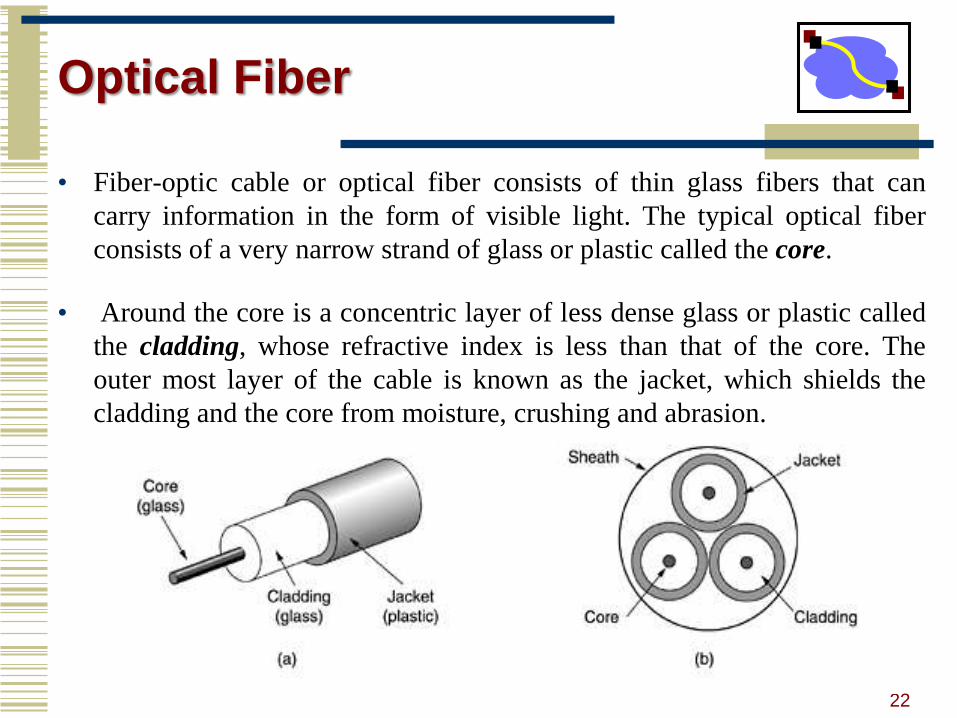
Optical Fiber
• Fiber-optic cable or optical fiber consists of thin glass fibers that can
carry information in the form of visible light. The typical optical fiber
consists of a very narrow strand of glass or plastic called the core.
• Around the core is a concentric layer of less dense glass or plastic called
the cladding, whose refractive index is less than that of the core. The
outer most layer of the cable is known as the jacket, which shields the
cladding and the core from moisture, crushing and abrasion.
22
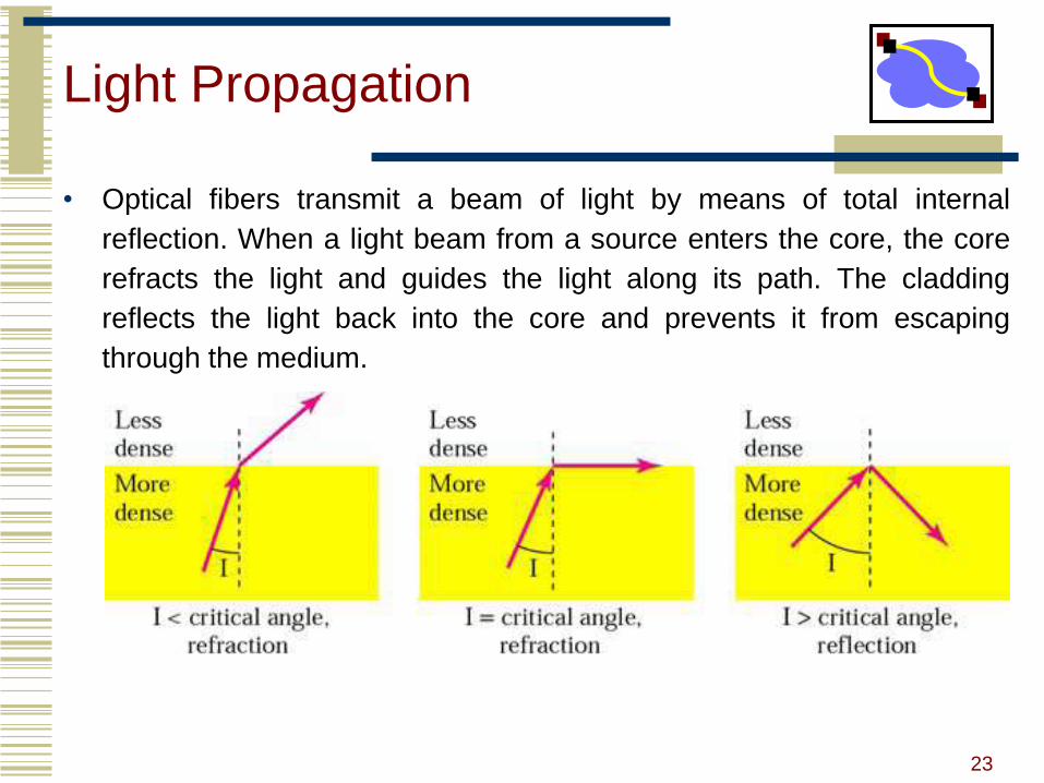
Light Propagation
• Optical fibers transmit a beam of light by means of total internal
reflection. When a light beam from a source enters the core, the core
refracts the light and guides the light along its path. The cladding
reflects the light back into the core and prevents it from escaping
through the medium.
23

Single mode Vs Multimode
• Fiber optic cables support two modes of propagating light, which are
multimode and single mode. In multimode, many beams from a light
source traverse along multiple paths and at multiple angles. In single
mode, the beams propagate almost horizontally.
24

Laser Connectors
• LED or LASER (Light Amplification by Stimulated Emission of Radiation)
acts as the source converting electric pulse to light pulses and photodiode acts
as receiver doing viceversa. Fiber optic cables uses 3 types of connectors,
which are :
• SC (Subscriber Connector)- used to connect cable TV
• ST (Straight Tip)- to connect network devices
• MT-RJ (Mechanical Transfer-Registered Jack)- for network applications.
25
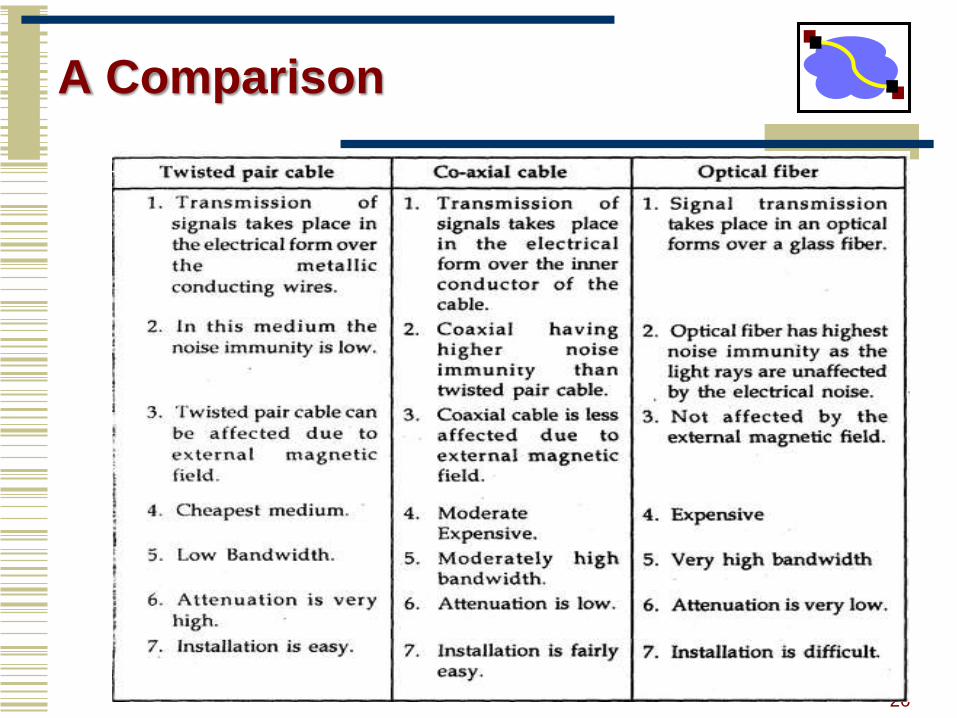
A Comparison
26

Physical Layer Devices
Cables
Connectors
Repeaters
Passive Hub
Simple Active Hub
Transmitters
Multiplexers
Receivers
Transceivers
Couplers