1 Cover Page TEST REPORT - tele.soumu.go.jp
55
SGS-CSTC Standards Technical Services Co., Ltd. Shenzhen Branch Report No.: SZEM190701621101 Page: 1 of 55 Keny Xu EMC Laboratory Manager 1 Cover Page TEST REPORT Application No.: SZEM1907016211CR Applicant: Dongguan Tonghai Electronic Technology Co., Ltd Address of Applicant: No.57, Nine Lane, xinwai, Xinan Avenue, Ludong Community, Humen Town, Dongguan City Manufacturer: Dongguan Tonghai Electronic Technology Co., Ltd Address of Manufacturer: No.57, Nine Lane, xinwai, Xinan Avenue, Ludong Community, Humen Town, Dongguan City Factory: Dongguan Tonghai Electronic Technology Co., Ltd Address of Factory: No.57, Nine Lane, xinwai, Xinan Avenue, Ludong Community, Humen Town, Dongguan City EUT Name: Low Power walkie talkie Model No.: T518, T568 Please refer to section 2 of this report which indicates which model was actually tested and which were electrically identical. Standards: Item 8 of Article 2 Paragraph 1 of Certification Ordinance Date of Receipt: 2019-07-11 Date of Test: 2019-07-11 to 2019-07-18 Date of Issue: 2019-07-22 Test Result: Pass* * In the configuration tested, the EUT detailed in this report complied with the standards specified above. Please refer to section 3 of this report for further detail.
Transcript of 1 Cover Page TEST REPORT - tele.soumu.go.jp

SGS-CSTC Standards Technical Services Co., Ltd. Shenzhen Branch
Report No.: SZEM190701621101
Page: 1 of 55
Keny Xu EMC Laboratory Manager
1 Cover Page
TEST REPORT Application No.: SZEM1907016211CR
Applicant: Dongguan Tonghai Electronic Technology Co., Ltd
Address of Applicant: No.57, Nine Lane, xinwai, Xinan Avenue, Ludong Community, Humen Town, Dongguan City
Manufacturer: Dongguan Tonghai Electronic Technology Co., Ltd
Address of Manufacturer: No.57, Nine Lane, xinwai, Xinan Avenue, Ludong Community, Humen Town, Dongguan City
Factory: Dongguan Tonghai Electronic Technology Co., Ltd
Address of Factory: No.57, Nine Lane, xinwai, Xinan Avenue, Ludong Community, Humen Town, Dongguan City
EUT Name: Low Power walkie talkie
Model No.: T518, T568
Please refer to section 2 of this report which indicates which model was actually tested and which were electrically identical.
Standards: Item 8 of Article 2 Paragraph 1 of Certification Ordinance
Date of Receipt: 2019-07-11
Date of Test: 2019-07-11 to 2019-07-18
Date of Issue: 2019-07-22
Test Result: Pass*
* In the configuration tested, the EUT detailed in this report complied with the standards specified above.
Please refer to section 3 of this report for further detail.

SGS-CSTC Standards Technical Services Co., Ltd.
Shenzhen Branch
Report No.: SZEM190701621101 Page: 2 of 55
2 Version
Revision Record
Version Chapter Date Modifier Remark
01 2019-07-22 Original
Authorized for issue by:
Bill Chen /Project Engineer
Eric Fu /Reviewer
SGS-CSTC Standards Technical Services Co., Ltd.
Shenzhen Branch
Report No.: SZEM190701621101 Page: 3 of 55
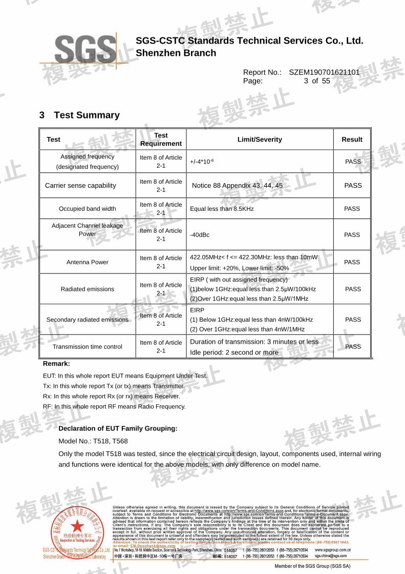
3 Test Summary
Test Test
Requirement Limit/Severity Result
Assigned frequency
(designated frequency)
Item 8 of Article
2-1 +/-4*10-6 PASS
Carrier sense capability Item 8 of Article
2-1 Notice 88 Appendix 43, 44, 45 PASS
Occupied band width Item 8 of Article
2-1 Equal less than 8.5KHz PASS
Adjacent Channel leakage
Power
Item 8 of Article
2-1 -40dBc PASS
Antenna Power Item 8 of Article
2-1
422.05MHz< f <= 422.30MHz: less than 10mW
Upper limit: +20%, Lower limit: -50% PASS
Radiated emissions Item 8 of Article
2-1
EIRP ( with out assigned frequency)
(1)below 1GHz:equal less than 2.5μW/100kHz
(2)Over 1GHz:equal less than 2.5μW/1MHz
PASS
Secondary radiated emissions Item 8 of Article
2-1
EIRP
(1) Below 1GHz:equal less than 4nW/100kHz
(2) Over 1GHz:equal less than 4nW/1MHz
PASS
Transmission time control Item 8 of Article
2-1
Duration of transmission: 3 minutes or less
Idle period: 2 second or more PASS
Remark:
EUT: In this whole report EUT means Equipment Under Test.
Tx: In this whole report Tx (or tx) means Transmitter.
Rx: In this whole report Rx (or rx) means Receiver.
RF: In this whole report RF means Radio Frequency.
Declaration of EUT Family Grouping:
Model No.: T518, T568
Only the model T518 was tested, since the electrical circuit design, layout, components used, internal wiring
and functions were identical for the above models, with only difference on model name.

SGS-CSTC Standards Technical Services Co., Ltd.
Shenzhen Branch
Report No.: SZEM190701621101 Page: 4 of 55
4 Contents
1 COVER PAGE ................................................................................................................................................... 1
2 VERSION ........................................................................................................................................................... 2
3 TEST SUMMARY .............................................................................................................................................. 3
4 CONTENTS ....................................................................................................................................................... 4
5 GENERAL INFORMATION ............................................................................................................................... 5
5.1 Details of E.U.T. ............................................................................................................................. 5
5.2 Test Conditions .............................................................................................................................. 5
5.3 Description of Support Units ......................................................................................................... 7
5.4 Deviation from Standards .............................................................................................................. 7
5.5 Abnormalities from Standard Conditions ...................................................................................... 7
5.6 Other Information Requested by the Customer ............................................................................ 7
5.7 Test Location ................................................................................................................................. 7
5.8 Test Facility .................................................................................................................................... 8
6 EQUIPMENT LIST ............................................................................................................................................. 9
7 TEST RESULTS .............................................................................................................................................. 10
7.1 Radio Technical Requirements Specification .............................................................................. 10
7.2 E.U.T. test conditions .................................................................................................................. 11
7.3 Antenna Requirement ................................................................................................................. 12
7.4 Interference prevention function ................................................................................................. 12
7.5 Assigned frequency ..................................................................................................................... 13
7.6 Carrier sense capability ............................................................................................................... 16
7.7 Occupied Bandwidth (99%) ......................................................................................................... 18
7.8 Adjacent Channel leakage Power ............................................................................................... 21
7.9 Antenna Power ............................................................................................................................ 25
7.10 Spurious Emissions of Tx ............................................................................................................ 29
7.11 Transmission time control ........................................................................................................... 37
7.12 Secondary radiated emissions of Rx .......................................................................................... 42
7.13 RF accessibility ........................................................................................................................... 48
8 PHOTOGRAPHS ............................................................................................................................................. 49
8.1 Test Setup ................................................................................................................................... 49
8.2 EUT Constructional Details ................................................................................................... 50-55

SGS-CSTC Standards Technical Services Co., Ltd.
Shenzhen Branch
Report No.: SZEM190701621101 Page: 5 of 55
5 General Information
5.1 Details of E.U.T.
Power supply: DC 6.0V by 1.5V x 4"AA" batteries
Test frequencies: 422.05MHz~422.30MHz
Modulation Type: FM
Number of Channels: 20
Channel Spacing: 12.5KHz
Antenna Type: Herical
Antenna Gain: -9.7dBi
5.2 Test Conditions
Power Supply DC 6.0V by 1.5V x 4"AA" batteries
The RF unit is supplied DC3.3V. The fluctuation of input voltage to the circuit
of RF unit of test equipment is under ±1%, when input voltage from DC6.0V to
the test equipment is fluctuated by ±10%, So, all measurement has been
conducted by only rated voltage.
The measurement result of the voltage fluctuation at RF circuit when
DC6.0V +/- 10%.
DC Input DC3V30 Result
6.6V 3.3328V 0.9939%
6V 3.30V 0%
5.4V 3.2671V -0.9970%
Temperature: 0 -45.0 C
Humidity: 45-85 % RH
Atmospheric
Pressure:
1000 -1010 mbar
Note:
VN: Normal Voltage
TN: Normal Temperature
TL: Low Extreme Test Temperature
TH: High Extreme Test Temperature

SGS-CSTC Standards Technical Services Co., Ltd.
Shenzhen Branch
Report No.: SZEM190701621101 Page: 6 of 55
Test Frequencies: If the EUT can be set to 3 of more different (carrier) frequencies in 1 allocated
band, testing shall be performed using the Lowest, Middle and the Highest
frequency (L, M and H). If there are 2 or fewer frequencies, testing shall be
performed with the available frequencies.
Operation Frequency each of channel
Channel Frequency Channel Frequency Channel Frequency Channel Frequency
1 422.0500MHz 6 422.1125MHz 11 422.1750MHz 16 422.2500MHz
2 422.0625MHz 7 422.1250MHz 12 422.2000MHz 17 422.2625MHz
3 422.0750MHz 8 422.1375MHz 13 422.2125MHz 18 422.2750MHz
4 422.0875MHz 9 422.1500MHz 14 422.2250MHz 19 422.2875MHz
5 422.1000MHz 10 422.1625MHz 15 422.2375MHz 20 422.300MHz
Selected Test Channel
Channel Frequency
The lowest channel 422.0500MHz
The middle channel 422.1625MHz
The highest channel 422.3000MHz

SGS-CSTC Standards Technical Services Co., Ltd.
Shenzhen Branch
Report No.: SZEM190701621101 Page: 7 of 55
5.3 Description of Support Units
The EUT has been tested as an independent unit for fixed frequency by testing lab.
5.4 Deviation from Standards
None.
5.5 Abnormalities from Standard Conditions
None.
5.6 Other Information Requested by the Customer
None.
5.7 Test Location
All tests were performed at:
SGS-CSTC Standards Technical Services Co., Ltd., Shenzhen Branch
No. 1 Workshop, M-10, Middle Section, Science & Technology Park, Shenzhen, Guangdong, China.
518057.
Tel: +86 755 2601 2053 Fax: +86 755 2671 0594
No tests were sub-contracted.

SGS-CSTC Standards Technical Services Co., Ltd.
Shenzhen Branch
Report No.: SZEM190701621101 Page: 8 of 55
5.8 Test Facility
The test facility is recognized, certified, or accredited by the following organizations:
• CNAS (No. CNAS L2929)
CNAS has accredited SGS-CSTC Standards Technical Services Co., Ltd. Shenzhen Branch EMC
Lab to ISO/IEC 17025:2005 General Requirements for the Competence of Testing and Calibration
Laboratories (CNAS-CL01 Accreditation Criteria for the Competence of Testing and Calibration
Laboratories) for the competence in the field of testing.
• A2LA (Certificate No. 3816.01)
SGS-CSTC Standards Technical Services Co., Ltd., Shenzhen EMC Laboratory is accredited by the
American Association for Laboratory Accreditation(A2LA). Certificate No. 3816.01.
• VCCI
The 3m Fully-anechoic chamber for above 1GHz, 10m Semi-anechoic chamber for below 1GHz,
Shielded Room for Mains Port Conducted Interference Measurement and Telecommunication Port
Conducted Interference Measurement of SGS-CSTC Standards Technical Services Co., Ltd. have
been registered in accordance with the Regulations for Voluntary Control Measures with Registration
No.: G-20026, R-14188, C-12383 and T-11153 respectively.
• FCC –Designation Number: CN1178
SGS-CSTC Standards Technical Services Co., Ltd., Shenzhen EMC Laboratory has been recognized
as an accredited testing laboratory.
Designation Number: CN1178. Test Firm Registration Number: 406779.
• Innovation, Science and Economic Development Canada
SGS-CSTC Standards Technical Services Co., Ltd., Shenzhen EMC Laboratory has been recognized
by ISED as an accredited testing laboratory.
CAB identifier: CN0006.
IC#: 4620C.
Remark:Our test report is under the quality assurance system according to ISO17025.

SGS-CSTC Standards Technical Services Co., Ltd.
Shenzhen Branch
Report No.: SZEM190701621101 Page: 9 of 55
6 Equipment List
Equipment list
Equipment Manufacturer Model No Inventory
No Cal Date
Cal Due
Date
Calibration
body Classification
DC Power
Supply ZhaoXin RXN-305D SEM011-02 2018-09-25 2019-09-24 CEPREI (c)
Spectrum
Analyzer
(20Hz-43GHz)
Rohde &
Schwarz FSU43 SEM004-08 2019-04-01 2020-03-31 CEPREI (c)
Signal
Generator
(9kHz-40GHz)
KEYSIGHT N5173B SEM006-05 2018-09-27 2019-09-26 CEPREI (c)
Multimeter FLUKE Fluke 73III SEM022-01 2019-04-03 2020-04-02 CEPREI (c)
Bluetooth
Tester
Rohde &
Schwarz CBT W060-01 2019-06-20 2020-06-19 CEPREI (c)
Universal
Radio
Communication
Tester
Rohde &
Schwarz CMW 500 SEM010-03 2019-04-02 2020-04-01 CEPREI (c)
Humidity/
Temperature
Indicator
Shanghai
Meteorological
Industry
Factory
ZJ1-2B SEM002-03 2018-09-27 2019-09-26 CEPREI (c)
Barometer
Changchun
Meteorological
Industry
Factory
DYM3 SEM002-01 2019-04-04 2020-04-03 CEPREI (c)
Remark:
(a) Calibration conducted by the National Institute of Information and Communications Technology (NICT) in
Japan (hereinafter referred to as "NICT") or a designated calibration agency under Article 102-18 paragraph (1)
in JRL.
(b) Correction conducted pursuant to the provisions of Article 135 or Article 144 of the Measurement Act (Act
No. 51 of 1992) .
(c) Calibration conducted in countries except Japan, which shall be equivalent to the calibration conducted by
the NICT or a designated calibration agency under Article 102-18 paragraph (1).
(d) Calibration, etc. conducted by using measuring instruments and other equipment listed in the right column of
appended table No. 3, which shall have been given any type of calibration, etc. listed above from (a) to (c).
From JRL Article 24-2, paragraph 4, Item 2

SGS-CSTC Standards Technical Services Co., Ltd.
Shenzhen Branch
Report No.: SZEM190701621101 Page: 10 of 55
7 Test Results
7.1 Radio Technical Requirements Specification
Tabel 1: Radio Technical Requirements Specification for 2.4 GHz band wide-band low-power data
communication system (Item 19 of Article 2-1)
Items Technical standard
Assigned frequency
( designated frequency) +/-4*10-6
Occupied band width Equal less than 8.5KHz
Antenna Power 422.05MHz< f <= 422.30MHz: less than 10mW
Upper limit: +20%, Lower limit: -50%
Adjacent Channel leakage Power
-40dBc
Radiated emissions
With out assigned frequency
(1) below 1GHz: equal less than 2.5μW/100kHz
(2) over 1GHz: equal less than 2.5μW/1MHz
Secondary radiated emissions (1) Below 1GHz: equal less than 4nW/100kHz
(2) over 1GHz: equal less than 4nW/1MHz
Transmission time control Duration of transmission: 3 minutes or less
Idle period: 2 second or more
Structure Shall be of the structure that the RF and modulator sections excluding
antenna cannot easily be opened.

SGS-CSTC Standards Technical Services Co., Ltd.
Shenzhen Branch
Report No.: SZEM190701621101 Page: 11 of 55
7.2 E.U.T. test conditions
Power supply: DC 6.0V by 1.5V x 4"AA" batteries
Test Voltage: rated voltage and ±10% of the rated voltage.
±10% of the rated voltage test is not required if EUT has a function of
AC/DC converter or AC/DC converter that is less than(or equal)±1%
fluctuation.
Temperature: 5.0 -35.0 C
Humidity: 45-85 % RH
Atmospheric Pressure: 1000 -1010 mbar
Test frequencies: 422.05MHz~422.30MHz
Modulation Type: FM
Number of Channels: 20
Channel Spacing: 12.5KHz
Antenna Type: Herical
Antenna Gain: -9.7dBi

SGS-CSTC Standards Technical Services Co., Ltd.
Shenzhen Branch
Report No.: SZEM190701621101 Page: 12 of 55
7.3 Antenna Requirement
Standard requirement
Applicable for equipment with an antenna terminal, including testing terminals) If an antenna
connector is available, all relevant tests will be carried out conducted. If not, tests will be carried out in
an anechoic room or with a suitable test-fixture.
EUT Antenna
The antenna is Herical antenna on the main PCB and no consideration of replacement. The best case
gain of the antenna is -9.7dBi.
Result: An antenna connector is available, all relevant tests will be carried out conducted
7.4 Interference prevention function
The transmitter consists of oscillator, transistor(to amplify the signal)and encoder; The oscillator
generate the 422.05MHz~422.30MHz frequency. The encoder generates a binary code set. A total of
20 code sets can be selectable via the DIP switches to avoid the interference from the same kind of
transmitter.The binary code is then transmitted to the antenna by the transistor.
Test result: The unit does meet the requirements.

SGS-CSTC Standards Technical Services Co., Ltd.
Shenzhen Branch
Report No.: SZEM190701621101 Page: 13 of 55
7.5 Assigned frequency
Test Requirement: Item 8 of Article 2-1
Limit +/-4*10-6
Test Status: Test the EUT in transmitting mode without modulation.
Test Configuration:
Test Procedure:
1. Test Conditions:
Spectrum Analyzer is used for measurement.
2. EUT conditions:
Modulation ON
EUT does not accept “Modulation OFF” mode in the measurement, use “Modulation ON” mode and the Max power
Frequency as the measuring results.
3. Spectrum Analyzer conditions:
Frequency: Assigned frequency
Span 3KHz
RBW 30Hz
VBW 30Hz
Sweep Time Auto
Detector mode Positive peak
Indication mode Max hold
Test result:
Test
Frequency
(MHz)
Test Result
Unit PPM Limit Normal
Voltage High Voltage Low Voltage
6.0V DC N/A N/A
422.050 422.04975 N/A N/A
(MHz)
-0.592*10-6
4*10-6 422.1625 422.16225 N/A N/A -0.592*10-6
422.300 422.29975 N/A N/A -0.520*10-6
EUT
Spectrum
Analyzer

SGS-CSTC Standards Technical Services Co., Ltd.
Shenzhen Branch
Report No.: SZEM190701621101 Page: 14 of 55
Note: The nominal frequency shall be confirmed by the applicant.
Result plot as follows:
Test Frequency (MHz):
Ref 20 dBm Att 20 dB*
*
*
Offset 0.9 dB
1 PK
VIEW
A
LVL
3DB
RBW 30 Hz
VBW 30 Hz
SWT 6.8 s
Center 422.05 MHz Span 3 kHz300 Hz/
-80
-70
-60
-50
-40
-30
-20
-10
0
10
20
1
Marker 1 [T1 ]
-4.71 dBm
422.049750000 MHz
Date: 20.JUL.2019 14:55:14

SGS-CSTC Standards Technical Services Co., Ltd.
Shenzhen Branch
Report No.: SZEM190701621101 Page: 15 of 55
Ref 20 dBm Att 20 dB*
*
*
Offset 0.9 dB
1 PK
VIEW
A
LVL
3DB
RBW 30 Hz
VBW 30 Hz
SWT 6.8 s
Center 422.1625 MHz Span 3 kHz300 Hz/
-80
-70
-60
-50
-40
-30
-20
-10
0
10
20
1
Marker 1 [T1 ]
-4.82 dBm
422.162245192 MHz
Date: 20.JUL.2019 14:56:58
Ref 20 dBm Att 20 dB*
*
*
Offset 0.9 dB
1 PK
VIEW
A
LVL
3DB
RBW 30 Hz
VBW 30 Hz
SWT 6.8 s
Center 422.3 MHz Span 3 kHz300 Hz/
-80
-70
-60
-50
-40
-30
-20
-10
0
10
20
1
Marker 1 [T1 ]
-4.71 dBm
422.299750000 MHz
Date: 20.JUL.2019 14:52:44
Test result: The unit does meet the requirements.

SGS-CSTC Standards Technical Services Co., Ltd.
Shenzhen Branch
Report No.: SZEM190701621101 Page: 16 of 55
7.6 Carrier sense capability
1) Measurement system diagram
(1) Test with test equipment only
2) Condition of measuring instrument
(1) Set the standard signal generator as follows:
Carrier frequency: Center frequency of receiving frequency band of test equipment
Modulation: No modulation.(note1)
Output level: >7uV
Note 1: The un-modulated carrier in the center frequency, when the carrier sense function of
test equipment is not worked, if necessary, change the frequency or modulate it.
(2) Set the spectrum analyzer as follows:
Center frequency: Center frequency of the bandwidth used.(note2)
Sweep frequency band: 50MHz(note2)
Resolution bandwidth: Approximately 1 MHz

SGS-CSTC Standards Technical Services Co., Ltd.
Shenzhen Branch
Report No.: SZEM190701621101 Page: 17 of 55
Video bandwidth: Comparable level with resolution bandwidth
Trigger condition: Free-run
Detective mode: positive peak
Note 2:Set sweep frequency band as 0Hz, detective mode as sample, center frequency as the
carrier frequency
3) Condition of test equipment
Set the test equipment at the test frequency and the test spread code, and set it to the receiving mode
in the beginning. When using external test device, connect with the test equipment by line connection.
4) Measuring operation procedure
(1) Test with test equipment only:
A) Set the spectrum analyzer according to (2) of 2).
B) Set the test equipment to the transmitting operation with the output of standard signal generator
OFF.
C) Set the test equipment to the receiving mode.
D) With the output of standard signal generator ON, set the test equipment to the transmitting
Operation.
5) Test result: The unit does meet the requirements (Good).

SGS-CSTC Standards Technical Services Co., Ltd.
Shenzhen Branch
Report No.: SZEM190701621101 Page: 18 of 55
7.7 Occupied Bandwidth (99%)
Test Requirement: Item 8 of Article 2-1
Equal less than 8.5KHz
Test Status: Pre-Scan has been conducted to determine the worst-case mode from
all possible combinations between available modulations, data rates
and antenna ports (if EUT with antenna diversity architecture).
Following channel(s) was (were) selected for the final test as listed
below.
Test Configuration:
Test Procedure:
1. Test Conditions:
Spectrum Analyzer is used for measurement.
2. EUT conditions:
Modulation Tx
For equipment using diffusion code, set to the test diffusion code and modulate with standard coding test signal.
3. Spectrum Analyzer conditions:
Frequency: Assigned Frequency
Span 20KHz
RBW 100Hz
VBW 100Hz
Sweep Time Auto
Detector mode Positive peak
Indication mode Max hold
OBW 99%
EUT
Spectrum
Analyzer
Audio soure

SGS-CSTC Standards Technical Services Co., Ltd.
Shenzhen Branch
Report No.: SZEM190701621101 Page: 19 of 55
Test result:
Test Frequency (MHz)
Test Result
Unit Limit Normal
Voltage High Voltage Low Voltage
6.0V DC N/A N/A
422.05 6.1 N/A N/A
kHz Equal less than
8.5KHz 422.1625 6.1 N/A N/A
422.30 6.5 N/A N/A
Result plot as follows:
Test Frequency (MHz):
Ref 20 dBm Att 20 dB*
*
*
Offset 0.9 dB
1 PK
VIEW
A
LVL
3DB
RBW 100 Hz
VBW 100 Hz
SWT 4 s
Center 422.05 MHz Span 20 kHz2 kHz/
-80
-70
-60
-50
-40
-30
-20
-10
0
10
20
1
Marker 1 [T1 ]
0.44 dBm
422.048493590 MHz
OBW 6.121794872 kHz
T1
Temp 1 [T1 OBW]
-19.99 dBm
422.046826923 MHz
T2
Temp 2 [T1 OBW]
-19.03 dBm
422.052948718 MHz
Date: 20.JUL.2019 15:08:39

SGS-CSTC Standards Technical Services Co., Ltd.
Shenzhen Branch
Report No.: SZEM190701621101 Page: 20 of 55
Ref 20 dBm Att 20 dB*
*
*
Offset 0.9 dB
1 PK
VIEW
A
LVL
3DB
RBW 100 Hz
VBW 100 Hz
SWT 4 s
Center 422.1625 MHz Span 20 kHz2 kHz/
-80
-70
-60
-50
-40
-30
-20
-10
0
10
20
1
Marker 1 [T1 ]
0.45 dBm
422.160993590 MHz
OBW 6.089743590 kHz
T1
Temp 1 [T1 OBW]
-20.37 dBm
422.159391026 MHz
T2
Temp 2 [T1 OBW]
-19.93 dBm
422.165480769 MHz
Date: 20.JUL.2019 15:10:44
Ref 20 dBm Att 20 dB*
*
*
Offset 0.9 dB
1 PK
VIEW
A
LVL
3DB
RBW 100 Hz
VBW 100 Hz
SWT 4 s
Center 422.3 MHz Span 20 kHz2 kHz/
-80
-70
-60
-50
-40
-30
-20
-10
0
10
20
1
Marker 1 [T1 ]
0.37 dBm
422.298493590 MHz
OBW 6.474358974 kHz
T1
Temp 1 [T1 OBW]
-19.01 dBm
422.296602564 MHz
T2
Temp 2 [T1 OBW]
-14.61 dBm
422.303076923 MHz
Date: 20.JUL.2019 15:06:50
Test result: The unit does meet the requirements.

SGS-CSTC Standards Technical Services Co., Ltd.
Shenzhen Branch
Report No.: SZEM190701621101 Page: 21 of 55
7.8 Adjacent Channel leakage Power
Test Requirement: Item 8 of Article 2-1
Limit:-40dBc
Test Status: Pre-Scan has been conducted to determine the worst-case mode from
all possible combinations between available modulations, data rates
and antenna ports (if EUT with antenna diversity architecture).
Following channel(s) was (were) selected for the final test as listed
below.
Test Configuration:
Test Procedure:
1. Test Conditions:
Spectrum Analyzer is used for measurement.
2. EUT conditions:
Modulation Tx
For equipment using diffusion code, set to the test diffusion code and modulate with standard coding test signal.
3. Spectrum Analyzer conditions:
Frequency: Assigned Frequency
Span 60KHz
RBW 100Hz
VBW 300Hz
Sweep Time Auto
Detector mode Positive RMS
Indication mode Average
EUT
Spectrum
Analyzer
Audio soure

SGS-CSTC Standards Technical Services Co., Ltd.
Shenzhen Branch
Report No.: SZEM190701621101 Page: 22 of 55
Test result:
Test
Frequency
(MHz):
Adjacent
channel
Test Result
Unit Limit
Normal
Voltage High Voltage Low Voltage
6.0V DC N/A N/A
422.05
+adjacent
channel -54.67 N/A N/A
dBc limit: -40dBc
-adjacent
channel -67.12 N/A N/A
422.1625
+adjacent
channel -56.80 N/A N/A
-adjacent
channel -66.99 N/A N/A
422.30
+adjacent
channel -48.69 N/A N/A
-adjacent
channel -65.87 N/A N/A
Result plot as follows:
Test Frequency (MHz): 422.05

SGS-CSTC Standards Technical Services Co., Ltd.
Shenzhen Branch
Report No.: SZEM190701621101 Page: 23 of 55
Ref 20 dBm Att 20 dB*
*
*
*
1 RM
VIEW
A
3DB
RBW 100 Hz
VBW 300 Hz
SWT 7.2 s
Center 422.05 MHz Span 60 kHz6 kHz/
-70
-60
-50
-40
-30
-20
-10
0
10
Tx Channel
Bandwidth 8.5 kHz Power 11.67 dBm
Adjacent Channel
Bandwidth 8.5 kHz Lower -54.67 dB Spacing 8.5 kHz Upper -67.12 dB
Alternate Channel
Bandwidth 8.5 kHz Lower -64.03 dB
Spacing 17 kHz Upper -69.52 dB
Date: 10.AUG.2019 11:17:09
Test Frequency (MHz): 422.1625
Ref 20 dBm Att 20 dB*
*
*
*
1 RM
VIEW
A
3DB
RBW 100 Hz
VBW 300 Hz
SWT 7.2 s
Center 422.1625 MHz Span 60 kHz6 kHz/
-70
-60
-50
-40
-30
-20
-10
0
10
Tx Channel
Bandwidth 8.5 kHz Power 10.05 dBm
Adjacent Channel
Bandwidth 8.5 kHz Lower -56.80 dB Spacing 8.5 kHz Upper -66.99 dB
Alternate Channel
Bandwidth 8.5 kHz Lower -61.40 dB
Spacing 17 kHz Upper -69.07 dB
Date: 10.AUG.2019 11:19:05
Test Frequency (MHz): 422.30

SGS-CSTC Standards Technical Services Co., Ltd.
Shenzhen Branch
Report No.: SZEM190701621101 Page: 24 of 55
Ref 20 dBm Att 20 dB*
*
*
*
1 RM
VIEW
A
3DB
RBW 100 Hz
VBW 300 Hz
SWT 7.2 s
Center 422.3 MHz Span 60 kHz6 kHz/
-70
-60
-50
-40
-30
-20
-10
0
10
Tx Channel
Bandwidth 8.5 kHz Power 11.46 dBm
Adjacent Channel
Bandwidth 8.5 kHz Lower -48.69 dB Spacing 8.5 kHz Upper -65.87 dB
Alternate Channel
Bandwidth 8.5 kHz Lower -69.28 dB
Spacing 17 kHz Upper -70.28 dB
Date: 10.AUG.2019 11:23:26
Test result: The unit does meet the requirements.

SGS-CSTC Standards Technical Services Co., Ltd.
Shenzhen Branch
Report No.: SZEM190701621101 Page: 25 of 55
7.9 Antenna Power
Test Requirement: Item 8 of Article 2-1
422.05MHz< f <= 422.30MHz: less than 10mW
Upper limit: +20%, Lower limit: -50%
Test Status: Pre-Scan has been conducted to determine the worst-case mode from
all possible combinations between available modulations, data rates
and antenna ports (if EUT with antenna diversity architecture).
Following channel(s) was (were) selected for the final test as listed
below.
Test Configuration:
Test Procedure:
4. Test Conditions:
Spectrum Analyzer is used for measurement.
5. EUT conditions:
Modulation Tx
For equipment using diffusion code, set to the test diffusion code and modulate with standard coding test signal.
6. Spectrum Analyzer conditions:
Frequency: Assigned Frequency
Span 1MHz
RBW 100KHz
VBW 100KHz
Sweep Time Auto
Detector mode Positive peak
Indication mode Max hold
EUT
Spectrum
Analyzer
Audio soure

SGS-CSTC Standards Technical Services Co., Ltd.
Shenzhen Branch
Report No.: SZEM190701621101 Page: 26 of 55
Test result:
Test
Frequency
(MHz):
Test Result
Unit Limit Normal Voltage High Voltage Low Voltage
6.0V DC N/A N/A
422.05 7.362 N/A N/A mW
422.05MHz< f <= 422.30MHz:
EIRP equal less than 10mW
Upper limit: +20%, Lower
limit: -50% 0 N/A N/A %
422.1625
7.362 N/A N/A mW 422.05MHz< f <= 422.30MHz:
EIRP equal less than 10mW
Upper limit: +20%, Lower
limit: -50% 0 N/A N/A %
422.30
7.362 N/A N/A mW 422.05MHz< f <= 422.30MHz:
EIRP equal less than 10mW
Upper limit: +20%, Lower
limit: -50% 0 N/A N/A %
Remark:
Antenna Power = Peak Power + Antenna Gain
Normal antenna power: 7.362 mW
Result plot as follows:
Test Frequency (MHz):

SGS-CSTC Standards Technical Services Co., Ltd.
Shenzhen Branch
Report No.: SZEM190701621101 Page: 27 of 55
Ref 20 dBm Att 20 dB*
*
*
Offset 0.9 dB
1 PK
VIEW
A
LVL
3DB
RBW 100 kHz
VBW 100 kHz
SWT 2.5 ms
Center 422.05 MHz Span 1 MHz100 kHz/
-80
-70
-60
-50
-40
-30
-20
-10
0
10
20
1
Marker 1 [T1 ]
8.67 dBm
422.050000000 MHz
Date: 20.JUL.2019 15:14:22
Ref 20 dBm Att 20 dB*
*
*
Offset 0.9 dB
1 PK
VIEW
A
LVL
3DB
RBW 100 kHz
VBW 100 kHz
SWT 2.5 ms
Center 422.1625 MHz Span 1 MHz100 kHz/
-80
-70
-60
-50
-40
-30
-20
-10
0
10
20
1
Marker 1 [T1 ]
8.67 dBm
422.164102564 MHz
Date: 20.JUL.2019 15:12:39

SGS-CSTC Standards Technical Services Co., Ltd.
Shenzhen Branch
Report No.: SZEM190701621101 Page: 28 of 55
Ref 20 dBm Att 20 dB*
*
*
Offset 0.9 dB
1 PK
VIEW
A
LVL
3DB
RBW 100 kHz
VBW 100 kHz
SWT 2.5 ms
Center 422.3 MHz Span 1 MHz100 kHz/
-80
-70
-60
-50
-40
-30
-20
-10
0
10
20
1
Marker 1 [T1 ]
8.67 dBm
422.298397436 MHz
Date: 20.JUL.2019 15:13:24
Test result: The unit does meet the requirements.
SGS-CSTC Standards Technical Services Co., Ltd.
Shenzhen Branch
Report No.: SZEM190701621101 Page: 29 of 55
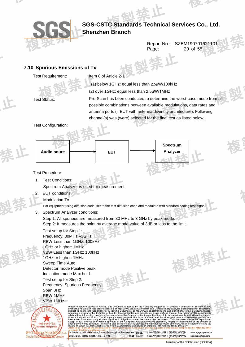
7.10 Spurious Emissions of Tx
Test Requirement: Item 8 of Article 2-1
(1) below 1GHz: equal less than 2.5μW/100kHz
(2) over 1GHz: equal less than 2.5μW/1MHz
Test Status: Pre-Scan has been conducted to determine the worst-case mode from all
possible combinations between available modulations, data rates and
antenna ports (if EUT with antenna diversity architecture). Following
channel(s) was (were) selected for the final test as listed below.
Test Configuration:
Test Procedure:
1. Test Conditions:
Spectrum Analyzer is used for measurement.
2. EUT conditions:
Modulation Tx
For equipment using diffusion code, set to the test diffusion code and modulate with standard coding test signal.
3. Spectrum Analyzer conditions:
Step 1: All spurious are measured from 30 MHz to 3 GHz by peak mode.
Step 2: It measures the point by average mode value of 3dB or less to the limit.
Test setup for Step 1:
Frequency: 30MHz –3GHz
RBW Less than 1GHz: 100kHz
1GHz or higher: 1MHz
VBW Less than 1GHz: 100kHz
1GHz or higher: 1MHz
Sweep Time Auto
Detector mode Positive peak
Indication mode Max hold
Test setup for Step 2:
Frequency: Spurious Frequency
Span 0Hz
RBW 1MHz
VBW 1MHz
EUT
Spectrum
Analyzer
Audio soure

SGS-CSTC Standards Technical Services Co., Ltd.
Shenzhen Branch
Report No.: SZEM190701621101 Page: 30 of 55
Sweep Time Auto
Detector mode Sample
Indication mode Max hold
Near the carrier frequency (step1)
Frequency: 422.05MHz, 422.1625MHz, 422.30MHz
RBW 3 kHz
VBW 3 kHz
Sweep Time Auto
Detector mode Single
Indication mode sample
Note1: Test Result = Reading + 15.2dB
15.2dB = 10 log (100 kHz / 3 kHz)
Near the carrier frequency (step2)
Frequency: searched frequency (see Note2)
Sweep Time Auto
Detector mode Single
Indication mode positive peak
Measurement mode: channel power measurement mode
Note2: In the case of search frequency is in 422.05-422.30MHz. Center frequency is 422.05MHz, 422.1625MHz,
422.30MHz
Note3: Spurious Emission = Test result + Antenna Gain

SGS-CSTC Standards Technical Services Co., Ltd.
Shenzhen Branch
Report No.: SZEM190701621101 Page: 31 of 55
Test result:
3KHz conversion to 100KHz value =10*log(100kHz/3kHz) = 15.2dB
422.050MHz
Test
Frequency
(MHz)
Test Result
Unit Limit Normal
Voltage
High
Voltage
Low
Voltage
6.0V DC N/A N/A
844.551 0.010 N/A N/A μW (1) below 1GHz: equal less than
2.5μW/100kHz
1266.026 0.204 N/A N/A
μW 2) over 1GHz: equal less than
2.5μW/1MHz 1958.333 0.042 N/A N/A
422.1625MHz
Test
Frequency
(MHz)
Test Result
Unit Limit Normal
Voltage
High
Voltage
Low
Voltage
6.0V DC N/A N/A
844.551 0.011 N/A N/A μW (1) below 1GHz: equal less than
2.5μW/100kHz
1266.026 0.196 N/A N/A
μW 2) over 1GHz: equal less than
2.5μW/1MHz 1958.333 0.043 N/A N/A
422.30MHz
Test
Frequency
(MHz)
Test Result
Unit Limit Normal
Voltage
High
Voltage
Low
Voltage
6.0V DC N/A N/A
844.551 0.011 N/A N/A μW (1) below 1GHz: equal less than
2.5μW/100kHz
1266.026 0.196 N/A N/A μW 2) over 1GHz: equal less than
2.5μW/1MHz

SGS-CSTC Standards Technical Services Co., Ltd.
Shenzhen Branch
Report No.: SZEM190701621101 Page: 32 of 55
1958.333 0.043 N/A N/A
Result plot as follows:
Test Frequency Range: 422.050MHz
30MHz –1GHz:
Ref 20 dBm Att 20 dB*
*
*
Offset 0.9 dB
1 PK
VIEW
A
LVL
3DB
RBW 3 kHz
VBW 3 kHz
SWT 225 ms
Center 422.05 MHz Span 2 MHz200 kHz/
-80
-70
-60
-50
-40
-30
-20
-10
0
10
20
1
Marker 1 [T1 ]
-60.49 dBm
421.987500000 MHz
2
Marker 2 [T1 ]
-55.62 dBm
421.819230769 MHz
3
Marker 3 [T1 ]
-57.37 dBm
422.112500000 MHz
4
Marker 4 [T1 ]
-55.18 dBm
422.274358974 MHz
D1 -26 dBm
Date: 17.AUG.2019 05:47:27

SGS-CSTC Standards Technical Services Co., Ltd.
Shenzhen Branch
Report No.: SZEM190701621101 Page: 33 of 55
Ref 20 dBm Att 20 dB*
*
*
Offset 0.9 dB
1 PK
VIEW
A
LVL
3DB
RBW 100 kHz
VBW 100 kHz
SWT 100 ms
Start 30 MHz Stop 1 GHz97 MHz/
-80
-70
-60
-50
-40
-30
-20
-10
0
10
20
1
Marker 1 [T1 ]
8.71 dBm
421.730769231 MHz
2
Marker 2 [T1 ]
-50.14 dBm
844.551282051 MHz
D1 -26 dBm
Date: 20.JUL.2019 15:24:28
1GHz –3GHz:
Ref 20 dBm Att 20 dB*
*
*
Offset 0.9 dB
1 PK
VIEW
A
LVL
3DB
RBW 1 MHz
VBW 1 MHz
SWT 5 ms
Start 1 GHz Stop 3 GHz200 MHz/
-80
-70
-60
-50
-40
-30
-20
-10
0
10
20
1
Marker 1 [T1 ]
-36.90 dBm
1.266025641 GHz
2
Marker 2 [T1 ]
-43.78 dBm
2.958333333 GHz
D1 -26 dBm
Date: 20.JUL.2019 15:20:22
Test Frequency Range: 422.1625MHz
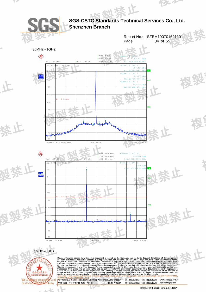
SGS-CSTC Standards Technical Services Co., Ltd.
Shenzhen Branch
Report No.: SZEM190701621101 Page: 34 of 55
30MHz –1GHz:
Ref 20 dBm Att 20 dB*
*
*
Offset 0.9 dB
1 PK
VIEW
A
LVL
3DB
RBW 3 kHz
VBW 3 kHz
SWT 225 ms
Center 422.1625 MHz Span 2 MHz200 kHz/
-80
-70
-60
-50
-40
-30
-20
-10
0
10
20
1
Marker 1 [T1 ]
-59.41 dBm
422.100000000 MHz
2
Marker 2 [T1 ]
-56.52 dBm
421.912179487 MHz
3
Marker 3 [T1 ]
-59.07 dBm
422.225000000 MHz
4
Marker 4 [T1 ]
-55.02 dBm
422.354487179 MHz
D1 -26 dBm
Date: 17.AUG.2019 05:43:04
Ref 20 dBm Att 20 dB*
*
*
Offset 0.9 dB
1 PK
VIEW
A
LVL
3DB
RBW 100 kHz
VBW 100 kHz
SWT 100 ms
Start 30 MHz Stop 1 GHz97 MHz/
-80
-70
-60
-50
-40
-30
-20
-10
0
10
20
1
Marker 1 [T1 ]
8.69 dBm
421.730769231 MHz
2
Marker 2 [T1 ]
-49.64 dBm
844.551282051 MHz
D1 -26 dBm
Date: 20.JUL.2019 15:25:22
1GHz –3GHz:

SGS-CSTC Standards Technical Services Co., Ltd.
Shenzhen Branch
Report No.: SZEM190701621101 Page: 35 of 55
Ref 20 dBm Att 20 dB*
*
*
Offset 0.9 dB
1 PK
VIEW
A
LVL
3DB
RBW 1 MHz
VBW 1 MHz
SWT 5 ms
Start 1 GHz Stop 3 GHz200 MHz/
-80
-70
-60
-50
-40
-30
-20
-10
0
10
20
1
Marker 1 [T1 ]
-37.07 dBm
1.266025641 GHz
2
Marker 2 [T1 ]
-43.66 dBm
2.958333333 GHz
D1 -26 dBm
Date: 20.JUL.2019 15:21:26
Test Frequency Range: 422.30MHz
30MHz –1GHz:
Ref 20 dBm Att 20 dB*
*
*
Offset 0.9 dB
1 PK
VIEW
A
LVL
3DB
RBW 3 kHz
VBW 3 kHz
SWT 225 ms
Center 422.3 MHz Span 2 MHz200 kHz/
-80
-70
-60
-50
-40
-30
-20
-10
0
10
20
1
Marker 1 [T1 ]
-60.25 dBm
422.237500000 MHz
2
Marker 2 [T1 ]
-56.68 dBm
422.001923077 MHz
3
Marker 3 [T1 ]
-61.97 dBm
422.362500000 MHz
4
Marker 4 [T1 ]
-56.87 dBm
422.546794872 MHz
D1 -26 dBm
Date: 17.AUG.2019 05:45:30
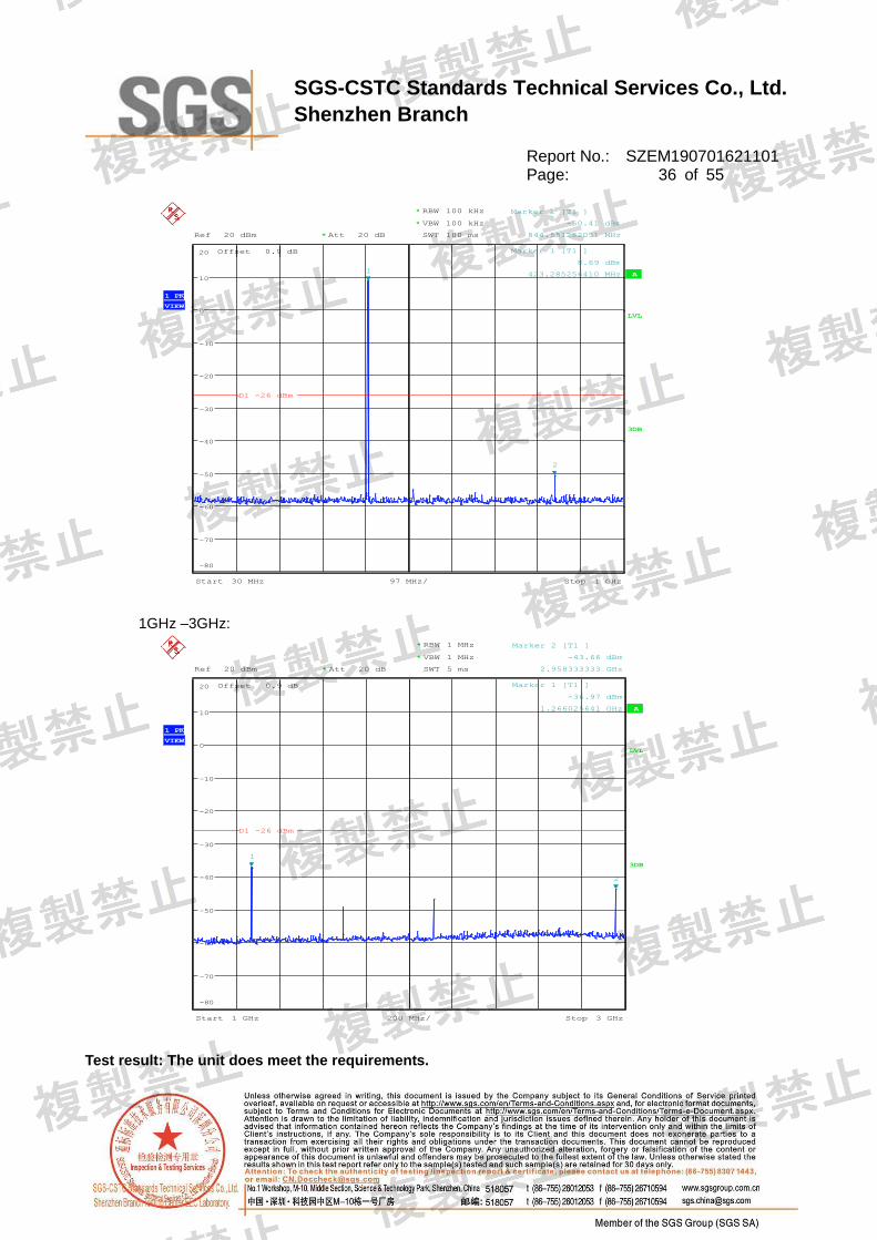
SGS-CSTC Standards Technical Services Co., Ltd.
Shenzhen Branch
Report No.: SZEM190701621101 Page: 36 of 55
Ref 20 dBm Att 20 dB*
*
*
Offset 0.9 dB
1 PK
VIEW
A
LVL
3DB
RBW 100 kHz
VBW 100 kHz
SWT 100 ms
Start 30 MHz Stop 1 GHz97 MHz/
-80
-70
-60
-50
-40
-30
-20
-10
0
10
20
1
Marker 1 [T1 ]
8.69 dBm
423.285256410 MHz
2
Marker 2 [T1 ]
-50.41 dBm
844.551282051 MHz
D1 -26 dBm
Date: 20.JUL.2019 15:23:29
1GHz –3GHz:
Ref 20 dBm Att 20 dB*
*
*
Offset 0.9 dB
1 PK
VIEW
A
LVL
3DB
RBW 1 MHz
VBW 1 MHz
SWT 5 ms
Start 1 GHz Stop 3 GHz200 MHz/
-80
-70
-60
-50
-40
-30
-20
-10
0
10
20
1
Marker 1 [T1 ]
-36.97 dBm
1.266025641 GHz
2
Marker 2 [T1 ]
-43.66 dBm
2.958333333 GHz
D1 -26 dBm
Date: 20.JUL.2019 15:22:24
Test result: The unit does meet the requirements.

SGS-CSTC Standards Technical Services Co., Ltd.
Shenzhen Branch
Report No.: SZEM190701621101 Page: 37 of 55
7.11 Transmission time control
Test Requirement: Item 8 of Article 2-1
Duration of transmission: 3 minutes or less
Idle period: 2 second or more
Test Status: Test the EUT in transmitting mode with modulation.
Test Configuration:
Test Procedure:
4. Test Conditions:
Spectrum Analyzer is used for measurement.
5. EUT conditions:
Switch ON
A manually operated transmitter shall employ a switch ON without 5 seconds of being released.
6. Spectrum Analyzer conditions:
Frequency: Assigned frequency
Span 0MHz
RBW 1MHz
VBW 1MHz
Sweep Time 210s
Detector mode Positive peak
Indication mode Max hold
EUT
Spectrum
Analyzer
Audio soure

SGS-CSTC Standards Technical Services Co., Ltd.
Shenzhen Branch
Report No.: SZEM190701621101 Page: 38 of 55
Test result:
Test
Frequency
(MHz)
Test Result
(transmissi
on)
Idle period
(Idle period) Unit Limit
422.050 177.3365 4 (Second)
Duration of transmission: 3
minutes or less
Idle period: 2 second or more 422.1625 177.3365 4 (Second)
422.30 177.3365 4 (Second)
Note: The nominal frequency shall be confirmed by the applicant.

SGS-CSTC Standards Technical Services Co., Ltd.
Shenzhen Branch
Report No.: SZEM190701621101 Page: 39 of 55
Result plot as follows:
Test Frequency:422.05MHz
Ref 20 dBm Att 20 dB*
*
*
Offset 0.9 dB
Center 422.05 MHz 21 s/
1 PK
VIEW
A
SGL
LVL
3DB
RBW 1 MHz
VBW 1 MHz
SWT 210 s
-80
-70
-60
-50
-40
-30
-20
-10
0
10
20
1
Marker 1 [T1 ]
9.42 dBm
13.798077 s 1
Delta 1 [T1 ]
-0.00 dB
175.336538 s
Date: 15.AUG.2019 07:08:04

SGS-CSTC Standards Technical Services Co., Ltd.
Shenzhen Branch
Report No.: SZEM190701621101 Page: 40 of 55
Test Frequency:422.1625MHz
Ref 20 dBm Att 20 dB*
*
*
Offset 0.9 dB
Center 422.1625 MHz 21 s/
1 PK
VIEW
A
SGL
LVL
3DB
RBW 1 MHz
VBW 1 MHz
SWT 210 s
-80
-70
-60
-50
-40
-30
-20
-10
0
10
20
1
Marker 1 [T1 ]
9.45 dBm
20.528846 s 1
Delta 1 [T1 ]
-0.02 dB
175.336538 s
Date: 15.AUG.2019 06:56:26
Test Frequency:422.30MHz

SGS-CSTC Standards Technical Services Co., Ltd.
Shenzhen Branch
Report No.: SZEM190701621101 Page: 41 of 55
Ref 20 dBm Att 20 dB*
*
*
Offset 0.9 dB
Center 422.3 MHz 21 s/
1 PK
VIEW
A
SGL
LVL
3DB
RBW 1 MHz
VBW 1 MHz
SWT 210 s
-80
-70
-60
-50
-40
-30
-20
-10
0
10
20
1
Marker 1 [T1 ]
9.43 dBm
17.163462 s 1
Delta 1 [T1 ]
-0.01 dB
175.336538 s
Date: 15.AUG.2019 07:03:37

SGS-CSTC Standards Technical Services Co., Ltd.
Shenzhen Branch
Report No.: SZEM190701621101 Page: 42 of 55
7.12 Secondary radiated emissions of Rx
Test Requirement: Item 8 of Article 2-1
(1) Below 1GHz : equal less than 4nW/100kHz
(2) over 1GHz : equal less than 4nW/1MHz
Test Status: Pre-Scan has been conducted to determine the worst-case mode from all
possible combinations between available modulations, data rates and
antenna ports (if EUT with antenna diversity architecture). Following
channel(s) was (were) selected for the final test as listed below.
Test Configuration:
Test Procedure:
1. Test Conditions:
Spectrum Analyzer is used for measurement.
2. EUT conditions:
Rx
3. Spectrum Analyzer conditions:
Step 1:All spurious are measured from 30 MHz to 3 GHz by peak mode.
Step 2:It measures the point by average mode value of 2dB or less to the limit.
Test setup for Step 1:
Frequency: 30MHz – 3GHz
RBW Less than 1GHz: 100kHz
1GHz or higher: 1MHz
VBW Less than 1GHz: 100kHz
1GHz and over: 1MHz
Sweep Time Auto
Detector mode Positive peak
Indication mode Max hold
EUT
Spectrum
Analyzer
Audio soure

SGS-CSTC Standards Technical Services Co., Ltd.
Shenzhen Branch
Report No.: SZEM190701621101 Page: 43 of 55
Test setup for Step 2:
Frequency: Spurious Frequency
Span 0Hz
RBW Less than 1GHz: 100kHz
1GHz and over: 1MHz
VBW Less than 1GHz : 100kHz
1GHz and over: 1MHz
Sweep Time Auto
detector mode Sample
Indication mode Max hold
Test result:
422.050MHz
Test
Frequency
(MHz)
Test Result
Unit Limit Normal
Voltage
High
Voltage
Low
Voltage
3.0V DC N/A N/A
911.3942 0.0377 N/A N/A nW Below 1GHz : equal less than
4nW/100kHz
2544.8718 0.1660 N/A N/A nW (2)Over 1GHz : equal less than
4nW/1MHz
422.1625MHz
Test
Frequency
(MHz)
Test Result
Unit Limit Normal
Voltage
High
Voltage
Low
Voltage
3.0V DC N/A N/A
51.7628 0.03589 N/A N/A nW Below 1GHz : equal less than
4nW/100kHz
2688 0.1528 N/A N/A nW (2)Over 1GHz : equal less than
4nW/1MHz
422.30MHz
Test
Frequency
(MHz)
Test Result
Unit Limit Normal
Voltage
High
Voltage
Low
Voltage
3.0V DC N/A N/A
937.92 0.03855 N/A N/A nW Below 1GHz : equal less than
4nW/100kHz
2688 0.1820 N/A N/A nW (2)Over 1GHz : equal less than
4nW/1MHz
Remark:

SGS-CSTC Standards Technical Services Co., Ltd.
Shenzhen Branch
Report No.: SZEM190701621101 Page: 44 of 55
Limit of secondary radiated emissions = Test result + Antenna Gain (RX)
Result plot as follows:
Test Frequency Range:422.050
30MHz –1GHz:
Ref 0 dBm Att 10 dB*
*
*
Offset 0.9 dB
1 PK
VIEW
A
LVL
3DB
RBW 100 kHz
VBW 100 kHz
SWT 100 ms
Start 30 MHz Stop 1 GHz97 MHz/
-100
-90
-80
-70
-60
-50
-40
-30
-20
-10
0
1
Marker 1 [T1 ]
-74.24 dBm
911.394230769 MHz
D1 -54 dBm
Date: 20.JUL.2019 15:16:00
1GHz –3GHz:

SGS-CSTC Standards Technical Services Co., Ltd.
Shenzhen Branch
Report No.: SZEM190701621101 Page: 45 of 55
Ref 0 dBm Att 10 dB*
*
*
Offset 0.9 dB
1 PK
VIEW
A
LVL
3DB
RBW 1 MHz
VBW 1 MHz
SWT 5 ms
Start 1 GHz Stop 3 GHz200 MHz/
-100
-90
-80
-70
-60
-50
-40
-30
-20
-10
0
1
Marker 1 [T1 ]
-67.80 dBm
2.544871795 GHz
D1 -54 dBm
Date: 20.JUL.2019 15:17:42
Test Frequency Range:422.1625MHz
30MHz –1GHz:
Ref 0 dBm Att 10 dB*
*
*
Offset 0.9 dB
1 PK
VIEW
A
LVL
3DB
RBW 100 kHz
VBW 100 kHz
SWT 100 ms
Start 30 MHz Stop 1 GHz97 MHz/
-100
-90
-80
-70
-60
-50
-40
-30
-20
-10
0
1
Marker 1 [T1 ]
-74.45 dBm
51.762820513 MHz
D1 -54 dBm
Date: 20.JUL.2019 15:16:29
1GHz –3GHz:

SGS-CSTC Standards Technical Services Co., Ltd.
Shenzhen Branch
Report No.: SZEM190701621101 Page: 46 of 55
Ref 0 dBm Att 10 dB*
*
*
Offset 0.9 dB
1 PK
VIEW
A
LVL
3DB
RBW 1 MHz
VBW 1 MHz
SWT 5 ms
Start 1 GHz Stop 3 GHz200 MHz/
-100
-90
-80
-70
-60
-50
-40
-30
-20
-10
0
1
Marker 1 [T1 ]
-68.16 dBm
2.830128205 GHz
D1 -54 dBm
Date: 20.JUL.2019 15:18:04
Test Frequency Range: 422.30MHz
30MHz –1GHz:
Ref 0 dBm Att 10 dB*
*
*
Offset 0.9 dB
1 PK
VIEW
A
LVL
3DB
RBW 100 kHz
VBW 100 kHz
SWT 100 ms
Start 30 MHz Stop 1 GHz97 MHz/
-100
-90
-80
-70
-60
-50
-40
-30
-20
-10
0
1
Marker 1 [T1 ]
-74.14 dBm
926.939102564 MHz
D1 -54 dBm
Date: 20.JUL.2019 15:17:02
1GHz –3GHz:

SGS-CSTC Standards Technical Services Co., Ltd.
Shenzhen Branch
Report No.: SZEM190701621101 Page: 47 of 55
Ref 0 dBm Att 10 dB*
*
*
Offset 0.9 dB
1 PK
VIEW
A
LVL
3DB
RBW 1 MHz
VBW 1 MHz
SWT 5 ms
Start 1 GHz Stop 3 GHz200 MHz/
-100
-90
-80
-70
-60
-50
-40
-30
-20
-10
0
1
Marker 1 [T1 ]
-67.40 dBm
2.676282051 GHz
D1 -54 dBm
Date: 20.JUL.2019 15:18:34

SGS-CSTC Standards Technical Services Co., Ltd.
Shenzhen Branch
Report No.: SZEM190701621101 Page: 48 of 55
7.13 RF accessibility
Standard requirement
Article 2, Item (19) Notice 88 Appendix 43, 44, 45
The EUT shall be constructed in such a way that sensitive RF parts, (like modulation and oscillator
parts) cannot be reached easily by the user. These parts shall be covered by soldered metal caps or
glue or by other mechanical covers. If the covers are fixed with screws, these shall be not the
common type(s) like a Phillips, but special versions like Torx, so that the user cannot open the device
with common tools.
Use shell snap protection to shield the internal structure.

SGS-CSTC Standards Technical Services Co., Ltd.
Shenzhen Branch
Report No.: SZEM190701621101 Page: 49 of 55
8 Photographs
8.1 Test Setup

SGS-CSTC Standards Technical Services Co., Ltd.
Shenzhen Branch
Report No.: SZEM190701621101 Page: 50 of 55
8.2 EUT Constructional Details

SGS-CSTC Standards Technical Services Co., Ltd.
Shenzhen Branch
Report No.: SZEM190701621101 Page: 51 of 55

SGS-CSTC Standards Technical Services Co., Ltd.
Shenzhen Branch
Report No.: SZEM190701621101 Page: 52 of 55

SGS-CSTC Standards Technical Services Co., Ltd.
Shenzhen Branch
Report No.: SZEM190701621101 Page: 53 of 55

SGS-CSTC Standards Technical Services Co., Ltd.
Shenzhen Branch
Report No.: SZEM190701621101 Page: 54 of 55

SGS-CSTC Standards Technical Services Co., Ltd.
Shenzhen Branch
Report No.: SZEM190701621101 Page: 55 of 55
--End of Report--